EP1024561B1 - A connector and a method for assembling the connector - Google Patents
A connector and a method for assembling the connector Download PDFInfo
- Publication number
- EP1024561B1 EP1024561B1 EP00200296A EP00200296A EP1024561B1 EP 1024561 B1 EP1024561 B1 EP 1024561B1 EP 00200296 A EP00200296 A EP 00200296A EP 00200296 A EP00200296 A EP 00200296A EP 1024561 B1 EP1024561 B1 EP 1024561B1
- Authority
- EP
- European Patent Office
- Prior art keywords
- cover
- cable
- shielding
- connector
- ferrule
- Prior art date
- Legal status (The legal status is an assumption and is not a legal conclusion. Google has not performed a legal analysis and makes no representation as to the accuracy of the status listed.)
- Expired - Lifetime
Links
Images
Classifications
-
- H—ELECTRICITY
- H01—ELECTRIC ELEMENTS
- H01R—ELECTRICALLY-CONDUCTIVE CONNECTIONS; STRUCTURAL ASSOCIATIONS OF A PLURALITY OF MUTUALLY-INSULATED ELECTRICAL CONNECTING ELEMENTS; COUPLING DEVICES; CURRENT COLLECTORS
- H01R13/00—Details of coupling devices of the kinds covered by groups H01R12/70 or H01R24/00 - H01R33/00
- H01R13/648—Protective earth or shield arrangements on coupling devices, e.g. anti-static shielding
- H01R13/658—High frequency shielding arrangements, e.g. against EMI [Electro-Magnetic Interference] or EMP [Electro-Magnetic Pulse]
- H01R13/6591—Specific features or arrangements of connection of shield to conductive members
- H01R13/65912—Specific features or arrangements of connection of shield to conductive members for shielded multiconductor cable
-
- H—ELECTRICITY
- H01—ELECTRIC ELEMENTS
- H01R—ELECTRICALLY-CONDUCTIVE CONNECTIONS; STRUCTURAL ASSOCIATIONS OF A PLURALITY OF MUTUALLY-INSULATED ELECTRICAL CONNECTING ELEMENTS; COUPLING DEVICES; CURRENT COLLECTORS
- H01R13/00—Details of coupling devices of the kinds covered by groups H01R12/70 or H01R24/00 - H01R33/00
- H01R13/46—Bases; Cases
- H01R13/502—Bases; Cases composed of different pieces
-
- H—ELECTRICITY
- H01—ELECTRIC ELEMENTS
- H01R—ELECTRICALLY-CONDUCTIVE CONNECTIONS; STRUCTURAL ASSOCIATIONS OF A PLURALITY OF MUTUALLY-INSULATED ELECTRICAL CONNECTING ELEMENTS; COUPLING DEVICES; CURRENT COLLECTORS
- H01R13/00—Details of coupling devices of the kinds covered by groups H01R12/70 or H01R24/00 - H01R33/00
- H01R13/62—Means for facilitating engagement or disengagement of coupling parts or for holding them in engagement
- H01R13/621—Bolt, set screw or screw clamp
- H01R13/6215—Bolt, set screw or screw clamp using one or more bolts
-
- H—ELECTRICITY
- H01—ELECTRIC ELEMENTS
- H01R—ELECTRICALLY-CONDUCTIVE CONNECTIONS; STRUCTURAL ASSOCIATIONS OF A PLURALITY OF MUTUALLY-INSULATED ELECTRICAL CONNECTING ELEMENTS; COUPLING DEVICES; CURRENT COLLECTORS
- H01R13/00—Details of coupling devices of the kinds covered by groups H01R12/70 or H01R24/00 - H01R33/00
- H01R13/648—Protective earth or shield arrangements on coupling devices, e.g. anti-static shielding
- H01R13/658—High frequency shielding arrangements, e.g. against EMI [Electro-Magnetic Interference] or EMP [Electro-Magnetic Pulse]
- H01R13/6591—Specific features or arrangements of connection of shield to conductive members
- H01R13/6592—Specific features or arrangements of connection of shield to conductive members the conductive member being a shielded cable
- H01R13/6593—Specific features or arrangements of connection of shield to conductive members the conductive member being a shielded cable the shield being composed of different pieces
Definitions
- the present invention relates to a connector, in accordance with the preamble of claim 1, and a method, according to the preamble of claim 8, for assembling the connector.
- the two washers causes also a "step" to pass for the electrical signals, which causes ineffectiveness and reduction in performance, when used for high-speed signals.
- ferrules cause disturbances of the signals in the connection area between the shielding and the cover in the connector, that means that the electrical signals from the earth screen, have to go backward via a squeezed metal ferrule and furthermore forward to the cover of the connector.
- US 4 963 104 discloses a shielded connector assembly in which a double bushing, comprising an outer and an inner bushing, is used.
- the inner bushing has grooves which mate with ridges on the conductive inner surface of the connector half shells.
- Screws according to known technique, for fastening the connector to the rack have to be screwed through threads in the connector after the assembly process of the cable and the connector. This also causes a high mounting cost.
- an object of the invention to overcome the disadvantages of the known devices and methods. That is, primary, to decrease the assembling time and the complexity of the connector and furthermore to improve the electrical characteristics for shielding and grounding function.
- said ferrule (15) comprises first (17), second (19) and third (24) parts, wherein the first part (17) can be crimped onto said cable jacket (3) for fastening said connecting means (13) to said cable (3) and the second part (19) can be crimped onto said cable shielding (7) for electrical communication, and the third part (24) makes electrical contact with the cover means (11, 12, 14).
- the electrical signals can be transported in a substantially smooth and straight direction, that means that improved electrical characteristics for the shielding and grounding function have been provided. Furthermore the surface-treatment of the covers will be much easier, as there is no small slot in which the electrical connection takes place.
- the connecting means comprises an inner ferrule which can be fastened substantially under the shielding to the outer ferrule in the area of the second part for making an axial locking between the outer ferrule and the cover means by means of at least one holding member at the inner ferrule.
- the cable can be locked in an axial direction in relation to the connector.
- the at least one tongue member forming said third part at the end of said second part is in contact with said cover means, and which at least one tongue member is oriented in an elongated direction of said outer ferrule for making a smooth and straight member for electrical communication.
- the signals can have an even and direct way from the cable shielding to the cover halves and vice versa.
- the at least one holding member of the inner ferrule is locked in a recess of the outer ferrule and the cover for making the connecting means non-rotatably.
- the at least one holding member is arranged substantially normal to the width of said connector, which width then is minimized, for making space around said connector.
- Using bigger dimension of the cables leads to an improved signalling capacity.
- the cover means is made of zinc.
- a conductive material for the shielding and grounding function is provided.
- rivets are made integral with one of said cover means. This means that the assembly-time is decreased and that no mounting of the rivets to the cover halves is needed.
- the rivets may be cast integral with the cover.
- the connector is furthermore assembled by a method described below.
- the disadvantages of the known methods have been solved by a method as defined in the introduction, comprising the steps of fitting an outer ferrule onto the cable, stripping a part of the jacket of the cable, cutting a part of the shielding for providing the shielding substantially the length of a second part of the outer ferrule, fitting an inner ferrule over the at least one conductor and under the shielding, sliding the outer ferrule back over the inner ferrule within the area of the second part, crimping the outer ferrule onto the inner ferrule, thereby trapping the cable shielding and making an electrical connection to the ferrules, and onto the cable jacket at the same time or substantially at the same time, terminating the at least one conductor into the terminal block, mounting the terminal block with the fitted cable and ferrules into the bottom cover and mounting the top cover to the bottom cover.
- the assembly-time for the assembly is decreased compared with known assemblies, due to that the crimping can be done in one step.
- the mounting of at least two screws into said bottom cover takes place before fitting said top cover to said bottom cover.
- the threads of the screws have also a function of stopping the screws to fall out during transport.
- the assembly-time is additionally decreased compared with known methods.
- said top cover is fitted to said bottom cover by means of deforming the head of rivets, which are integrated in the bottom or top cover.
- the rivets may be cast integral with the cover. This means that the assembly-time is further decreased.
- the integrated rivets leads to that the manufacturing of the cover and rivets is more uncomplicated, since no mounting of the rivets to the halves has to be done. Further more it is easier fitting the two cover halves together, since the rivets already are in their position.
- a connector 9 for connection to a cable 3, with a number of conductors 5 within a, for example, braided shielding 7, a connector 9 comprises first and second cover halves 12, 14, which are designed for electrical communication.
- the cover halves 12, 14 can be made of zinc. They are designed for making a connection between a connection means 13, which, according to the invention, is an outer ferrule 15, which is in contact with the braided shielding 7 of the cable 3, and a socket (not shown) in a rack (not shown).
- the surfaces 11 of the cover halves 12, 14 can be made even and smooth, with no slots or other sharp members in the electrical path.
- the cover halves 12, 14 are in figure 1 mechanically connectable to a terminal block 8.
- the connector comprises furthermore an inner ferrule 21, which is located under the shielding 7 of the cable 3, that is between the shielding 7 and the conductors 5.
- the shielding 7 is illustrated in a cut of the jacket 4.
- a first part 17 is crimped onto the jacket 4 of the cable 3 and a second part 19 is crimped onto the shielding 7. That means that the jacket 4 is stripped in the area of the second part 19 for making a contact with the shielding 7.
- the outer ferrule 15 is accordingly to the invention during the assembly process at the same time crimped onto the jacket 4 of the cable 3 and onto respectively the shielding 7 and the inner ferrule 21 with respectively the first part 17 and the second part 19 of the outer ferrule 15.
- the inner ferrule 21 is provided with at least one lug 23.
- the inner ferrule 21 is here provided with two lugs 23, which each are located in a recess 25 at the end of the second part 19 of the outer ferrule 15 and in the cover.
- the lugs 23 are in the figure 1 and 2b, seen as illustrated, arranged in a vertical direction in relation to the width for decreasing the width of the connector 9. If the lugs 23 should be arranged horizontally, the height could be decreased instead.
- the top cover 14 and a bottom cover 12 have a surface 11 (shown in fig. 3) inside for electrical communication.
- the surface 11 could be zinc with a suitable plating (for example copper, nickel, tin etc).
- the outer ferrule 15 has to be in contact with the surface 11. This is made by means of springing tongues 24 of the outer ferrule 15, which are in contact with the surface 11 of the first and second cover halves 12, 14.
- Screws 29, 30, each provided with a threaded and an unthreaded part are located in respectively two ear halves 31, 32 before fitting the top cover 14 to the bottom cover 12. This means that no threads in the ears 31, 32 have to be done. This means that the strength of the ears can be increased, as the ears 31, 32 can be made thicker.
- rivets 34 are made in one part with the bottom cover 12. This means that the assembly process can be done more easily than before, since no external rivets have to be pre-mounted in the bottom cover 12 before fitting the bottom cover 12 to the top cover 14.
- Figure 4 illustrates the above described example of the invention, in which parts denoted with a reference sign correspond to parts described in figure 1, 2a, 2b and 3.
- Figure 4 shows by means of an arrow E schematically the smooth and substantial straight path of the electrical signal flow from the braided shielding 7 to the two cover halves 12, 14.
- the springing tongues 24 By means of the springing tongues 24, a contact between the outer ferrule 15 and the braided shielding 7 and the cover halves 12, 14 is provided. This means that an electrical communication can take place between the shielding 7 and the cover 12 via the outer ferrule 15 and its springing tongues 24. As the springing tongues 24 have their location in the extension length of the outer ferrule 15, the communication can take place without making any sharp and abrupt transition section.
- Known technique means that the electrical signals have to made a sharp and abrupt transition way in the area between the shielding and the cover.
- Today used spring washers cause a sharp path for the signals.
- known ferrules causes a non-smooth communication between the shielding and the surface of the cover halves or the cover. It is according to known technique a problem for the surface to have an even thickness all over the area for electrical communication.
- Known technique means that the crimping operation, during the assembling process, of the ferrules to the jacket must be done in two steps.
- the electrical signals can make a smooth and straight path. This leads to an improved electrical performance for, for example, the shielding and the grounding function.
- the inner ferrule is provided with a member for preventing a rotation of the cable. This member also locks the cable in an axial direction. Also may hooks, arranged to the cover, be used for hooking the outer ferrule to the cover.
- the covers may be made with rounded external corners. This will, while plaiting the cables with associated connectors, make the plaiting easier to control, since the covers will not damage each other during, for example, a trumbeling process.
Abstract
Description
- The present invention relates to a connector, in accordance with the preamble of claim 1, and a method, according to the preamble of
claim 8, for assembling the connector. - Known methods for assembling shielded cable connectors, as, for example, the one disclosed in US 4 902 249, suffers from the disadvantage that the assembling process time is long, causing a high manufacturing cost.
- According to one of the prior art methods, it is difficult to assemble the connector, as in this specific technique two spring washers are needed, for contacting the shielding of the cable and the cover of the cable connector for EMC-protection.
- The two washers, according to this known technique, causes also a "step" to pass for the electrical signals, which causes ineffectiveness and reduction in performance, when used for high-speed signals.
- Also ferrules, according for example to US 4 902 249, cause disturbances of the signals in the connection area between the shielding and the cover in the connector, that means that the electrical signals from the earth screen, have to go backward via a squeezed metal ferrule and furthermore forward to the cover of the connector.
- US 4 963 104 discloses a shielded connector assembly in which a double bushing, comprising an outer and an inner bushing, is used. The inner bushing has grooves which mate with ridges on the conductive inner surface of the connector half shells.
- Known cable connectors, suffer furthermore from the disadvantage that existing racks do not allow larger dimensions for the cables, since the connectors, according to known techniques already are in a tight position between each other when maled. Larger dimension of the cable gives a better signal performance. It is also a problem for operating personnel to get their fingers around the connector, since there is no sufficient space between the connectors, when mounted in the rack.
- Furthermore rivets, according to known technique, have to be mounted before or after the assembly process of the connectors for riveting. This causes a complicated assembly of the connector and high costs.
- Screws, according to known technique, for fastening the connector to the rack have to be screwed through threads in the connector after the assembly process of the cable and the connector. This also causes a high mounting cost.
- It is, accordingly, an object of the invention to overcome the disadvantages of the known devices and methods. That is, primary, to decrease the assembling time and the complexity of the connector and furthermore to improve the electrical characteristics for shielding and grounding function.
- The above mentioned objects have been solved by a connector as defined in the introduction, which is characterized in that said ferrule (15) comprises first (17), second (19) and third (24) parts, wherein the first part (17) can be crimped onto said cable jacket (3) for fastening said connecting means (13) to said cable (3) and the second part (19) can be crimped onto said cable shielding (7) for electrical communication, and the third part (24) makes electrical contact with the cover means (11, 12, 14).
- Hereby the electrical signals can be transported in a substantially smooth and straight direction, that means that improved electrical characteristics for the shielding and grounding function have been provided. Furthermore the surface-treatment of the covers will be much easier, as there is no small slot in which the electrical connection takes place.
- Suitably, the connecting means comprises an inner ferrule which can be fastened substantially under the shielding to the outer ferrule in the area of the second part for making an axial locking between the outer ferrule and the cover means by means of at least one holding member at the inner ferrule. In this way the cable can be locked in an axial direction in relation to the connector.
- Preferably, the at least one tongue member forming said third part at the end of said second part is in contact with said cover means, and which at least one tongue member is oriented in an elongated direction of said outer ferrule for making a smooth and straight member for electrical communication. Hereby the signals can have an even and direct way from the cable shielding to the cover halves and vice versa.
- Suitably, the at least one holding member of the inner ferrule is locked in a recess of the outer ferrule and the cover for making the connecting means non-rotatably. An advantage of this arrangement is that the cable is prevented to rotate relatively to the connector body.
- Preferably, the at least one holding member is arranged substantially normal to the width of said connector, which width then is minimized, for making space around said connector. This allows that cables with bigger dimension can be connected to the connector according to the invention, since the connection means according to the invention compared with known connection means, makes it possible to use cables with bigger dimension, without increasing the width of the connector. Using bigger dimension of the cables leads to an improved signalling capacity. This also leads to improved electrical characteristics for the shielding and grounding function. Furthermore may a reduction of the size of the connectors for existing cable dimensions be provided, which makes more space between adjacent cable connectors according to the invention. This makes it possible to get your fingers around the cable connector body in a god manner, without forcing operating personal to pull on the cable when disconnecting the cable connector from for example a PCB connector.
- Suitably, the cover means is made of zinc. Hereby a conductive material for the shielding and grounding function is provided.
- Preferably, rivets are made integral with one of said cover means. This means that the assembly-time is decreased and that no mounting of the rivets to the cover halves is needed. The rivets may be cast integral with the cover.
- The connector, according to the invention, is furthermore assembled by a method described below. The disadvantages of the known methods have been solved by a method as defined in the introduction, comprising the steps of fitting an outer ferrule onto the cable, stripping a part of the jacket of the cable, cutting a part of the shielding for providing the shielding substantially the length of a second part of the outer ferrule, fitting an inner ferrule over the at least one conductor and under the shielding, sliding the outer ferrule back over the inner ferrule within the area of the second part, crimping the outer ferrule onto the inner ferrule, thereby trapping the cable shielding and making an electrical connection to the ferrules, and onto the cable jacket at the same time or substantially at the same time, terminating the at least one conductor into the terminal block, mounting the terminal block with the fitted cable and ferrules into the bottom cover and mounting the top cover to the bottom cover.
- Hereby the assembly-time for the assembly is decreased compared with known assemblies, due to that the crimping can be done in one step. Furthermore other steps according to the invention, compared with known methods, means shorter assembly-time. Preferably, the mounting of at least two screws into said bottom cover takes place before fitting said top cover to said bottom cover. The threads of the screws have also a function of stopping the screws to fall out during transport. Hereby the assembly-time is additionally decreased compared with known methods.
- Suitably, wherein said top cover is fitted to said bottom cover by means of deforming the head of rivets, which are integrated in the bottom or top cover. The rivets may be cast integral with the cover. This means that the assembly-time is further decreased. The integrated rivets leads to that the manufacturing of the cover and rivets is more uncomplicated, since no mounting of the rivets to the halves has to be done. Further more it is easier fitting the two cover halves together, since the rivets already are in their position.
- The invention will now be described more closely by means of an example of an embodiment with reference to the accompanying drawings, in which
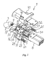
- Figure 1 illustrates in a view of perspective a connector according to the invention,
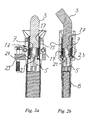
- Figure 2a illustrates a cross section of the connector in figure 1,
- Figure 2b illustrates a cross section of the connector in figure 2a,
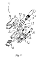
- Figure 3 illustrates a exploded view of the connector according to the invention,
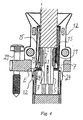
- Figure 4 illustrates an enlarged view of the cross section in section 2a.
-
- Referring to figure 1, 2a, 2b and 3, according to the invention, for connection to a
cable 3, with a number ofconductors 5 within a, for example, braidedshielding 7, aconnector 9 comprises first andsecond cover halves cover halves outer ferrule 15, which is in contact with thebraided shielding 7 of thecable 3, and a socket (not shown) in a rack (not shown). According to the invention the surfaces 11 of thecover halves cover halves cover halves terminal block 8. - The connector comprises furthermore an
inner ferrule 21, which is located under the shielding 7 of thecable 3, that is between the shielding 7 and theconductors 5. In figure 1 theshielding 7 is illustrated in a cut of thejacket 4. Afirst part 17 is crimped onto thejacket 4 of thecable 3 and asecond part 19 is crimped onto theshielding 7. That means that thejacket 4 is stripped in the area of thesecond part 19 for making a contact with theshielding 7. Theouter ferrule 15 is accordingly to the invention during the assembly process at the same time crimped onto thejacket 4 of thecable 3 and onto respectively the shielding 7 and theinner ferrule 21 with respectively thefirst part 17 and thesecond part 19 of theouter ferrule 15. - The
inner ferrule 21 is provided with at least onelug 23. At the drawings theinner ferrule 21 is here provided with twolugs 23, which each are located in arecess 25 at the end of thesecond part 19 of theouter ferrule 15 and in the cover. Thelugs 23 are in the figure 1 and 2b, seen as illustrated, arranged in a vertical direction in relation to the width for decreasing the width of theconnector 9. If thelugs 23 should be arranged horizontally, the height could be decreased instead. - The
top cover 14 and abottom cover 12 have a surface 11 (shown in fig. 3) inside for electrical communication. The surface 11 could be zinc with a suitable plating (for example copper, nickel, tin etc). Theouter ferrule 15 has to be in contact with the surface 11. This is made by means of springingtongues 24 of theouter ferrule 15, which are in contact with the surface 11 of the first and second cover halves 12, 14. -
Screws ear halves top cover 14 to thebottom cover 12. This means that no threads in theears ears - As illustrated in figure 1 and 3, rivets 34 are made in one part with the
bottom cover 12. This means that the assembly process can be done more easily than before, since no external rivets have to be pre-mounted in thebottom cover 12 before fitting thebottom cover 12 to thetop cover 14. - Figure 4 illustrates the above described example of the invention, in which parts denoted with a reference sign correspond to parts described in figure 1, 2a, 2b and 3. Figure 4 shows by means of an arrow E schematically the smooth and substantial straight path of the electrical signal flow from the braided shielding 7 to the two
cover halves - By means of the springing
tongues 24, a contact between theouter ferrule 15 and the braided shielding 7 and the cover halves 12, 14 is provided. This means that an electrical communication can take place between the shielding 7 and thecover 12 via theouter ferrule 15 and its springingtongues 24. As the springingtongues 24 have their location in the extension length of theouter ferrule 15, the communication can take place without making any sharp and abrupt transition section. - Known technique means that the electrical signals have to made a sharp and abrupt transition way in the area between the shielding and the cover. Today used spring washers cause a sharp path for the signals. Also known ferrules causes a non-smooth communication between the shielding and the surface of the cover halves or the cover. It is according to known technique a problem for the surface to have an even thickness all over the area for electrical communication. Known technique means that the crimping operation, during the assembling process, of the ferrules to the jacket must be done in two steps.
- According to the invention, the electrical signals, either coming from the cable to the cover or vice versa, can make a smooth and straight path. This leads to an improved electrical performance for, for example, the shielding and the grounding function.
- When handling with the cables and the fitted connectors and they, for example, being mounted in a rack, a twisting moment causes rotational forces to the cables and the connectors. According to the invention, the inner ferrule is provided with a member for preventing a rotation of the cable. This member also locks the cable in an axial direction. Also may hooks, arranged to the cover, be used for hooking the outer ferrule to the cover.
- The covers may be made with rounded external corners. This will, while plaiting the cables with associated connectors, make the plaiting easier to control, since the covers will not damage each other during, for example, a trumbeling process.
Claims (9)
- A connector for a cable (3) with at least one conductor (5) and a shielding (7), which connector (9) comprises cover means (11, 12, 14), said cover means comprising cover halves (12, 14) and having a surface (11) designed for electrical communication, and a connecting means (13) connectable to the shielding (7) and the cover halves (12,14), wherein said connecting means (13) comprises an outer ferrule (15) characterized in that said ferrule (15) comprises first (17), second (19) and third (24) parts, wherein the first part (17) can be crimped onto said cable jacket (3) for fastening said connecting means (13) to said cable (3) and the second part (19) can be crimped onto said cable shielding (7) for electrical communication, and the third part (24) makes electrical contact with the cover means (11, 12, 14).
- A connector according to claim 1, wherein said connecting means (13) also comprises an inner ferrule (21) fastened substantially under said shielding (7) to said outer ferrule (15) in the area of the second part (19) for making an axial locking between said outer ferrule (15) and said cover means (11, 12, 14) by means of at least one holding member (23) at said inner ferrule (21).
- A connector according to claim 1, wherein at least one tongue member (24) forming said third part at the end of said second part (19) is in contact with said cover means (11, 12, 14), and which at least one tongue member (24) is oriented in an elongated direction of said outer ferrule (15) for making a smooth and straight member for electrical communication.
- A connector according to claim 2, wherein said at least one holding member (23) of said inner ferrule (21) is locked in a recess (25) of said outer ferrule (15) and said cover means (11, 12, 14) for making said connecting means (13) non-rotatably.
- A connector according to claims 2 or 4, wherein said at least one holding member (23) is substantially arranged normal to the width of said connector (9), which width then is minimized, for making space around said connector (9).
- A connector according to anyone of the preceding claims, wherein said cover means (11, 12, 14) is made of zinc with a suitably plating.
- A connector according to anyone of the preceding claims, wherein rivets (34) are integral with one of said cover means (11, 12, 14).
- A method for assembling a cable (3) with a connector (9) according to claim 1, which cable (3) comprises at least one conductor (5) and shielding (7) and which connector (9) comprises a cover means (11, 12, 14) designed for electrical communication and comprising a bottom cover (12) and a top cover (14) and a surface (11), a terminal block (8) and a connecting means (13) connectable to the shielding (7) and the cover means (11, 12, 14), comprising the steps of fitting an outer ferrule (15) onto said cable (3), stripping a part of the jacket (4) of said cable (3), cutting a part of the shielding for providing said shielding (7) substantially the length of a second part (19) of said outer ferrule (15), fitting an inner ferrule (21) over said at least one conductor (5) and under said shielding (7), sliding said outer ferrule (15) back over said inner ferrule (21) within the area of said second part (19), crimping said outer ferrule (15) onto said inner ferrule (21) for trapping said cable shielding (7) and making an electrical connection to said ferrules (15, 21), and onto said cable jacket (3) at the same time or substantially at the same time, terminating said at least one conductor (5) into said terminal block (8), mounting the terminal block (8) with the fitted cable (3) and ferrules (15, 21) into said bottom cover (12) and mounting said top cover (14) to said bottom cover (12).
- A method according to claim 8, including the step of mounting at least two screws (29, 30) into said bottom cover (12) before fitting said top cover (14) to said bottom cover (12).
Applications Claiming Priority (2)
| Application Number | Priority Date | Filing Date | Title |
|---|---|---|---|
| SE9900299A SE520444C2 (en) | 1999-01-29 | 1999-01-29 | Connectors and method for assembling the connector |
| SE9900299 | 1999-01-29 |
Publications (3)
| Publication Number | Publication Date |
|---|---|
| EP1024561A2 EP1024561A2 (en) | 2000-08-02 |
| EP1024561A3 EP1024561A3 (en) | 2000-08-09 |
| EP1024561B1 true EP1024561B1 (en) | 2003-10-01 |
Family
ID=20414289
Family Applications (1)
| Application Number | Title | Priority Date | Filing Date |
|---|---|---|---|
| EP00200296A Expired - Lifetime EP1024561B1 (en) | 1999-01-29 | 2000-01-28 | A connector and a method for assembling the connector |
Country Status (5)
| Country | Link |
|---|---|
| US (1) | US6203377B1 (en) |
| EP (1) | EP1024561B1 (en) |
| AT (1) | ATE251349T1 (en) |
| DE (1) | DE60005577T2 (en) |
| SE (1) | SE520444C2 (en) |
Families Citing this family (17)
| Publication number | Priority date | Publication date | Assignee | Title |
|---|---|---|---|---|
| US6338645B1 (en) * | 2000-07-28 | 2002-01-15 | Apple Computer, Inc. | Connector having a cable that is relatively moveable about an axis |
| NL1022159C2 (en) * | 2002-12-13 | 2004-06-15 | Framatome Connectors Int | Cable connector and method for manufacturing a cable connector. |
| NL1022225C2 (en) * | 2002-12-20 | 2004-06-22 | Framatome Connectors Int | Cable connector and method for joining a cable and such a cable connector. |
| TW573839U (en) * | 2003-06-27 | 2004-01-21 | Hon Hai Prec Ind Co Ltd | Cable connector assembly |
| US7033219B2 (en) * | 2004-06-10 | 2006-04-25 | Commscope Solutions Properties, Llc | Modular plug assemblies, terminated cable assemblies and methods for forming the same |
| US7083472B2 (en) | 2004-06-10 | 2006-08-01 | Commscope Solutions Properties, Llc | Shielded jack assemblies and methods for forming a cable termination |
| NL1026451C2 (en) | 2004-06-18 | 2005-12-20 | Framatome Connectors Int | Cable connector and method for assembling a cable and such a cable connector. |
| JP4909793B2 (en) * | 2007-04-18 | 2012-04-04 | 住友電装株式会社 | Shield connector |
| EP2184812A1 (en) * | 2008-11-06 | 2010-05-12 | Hon Hai Precision Industry Co., Ltd. | Cable end connector assembly |
| DE202009015571U1 (en) * | 2009-11-14 | 2011-03-24 | Wieland Electric Gmbh | Electrical connector |
| CN102340081B (en) * | 2010-07-16 | 2014-12-24 | 富士康(昆山)电脑接插件有限公司 | Cable connector assembly |
| US9124008B2 (en) * | 2013-08-29 | 2015-09-01 | Tyco Electronics Corporation | Electrical connector |
| JP6610954B2 (en) * | 2016-06-01 | 2019-11-27 | 住友電装株式会社 | Shield connector |
| CN106785591B (en) * | 2017-01-23 | 2019-09-03 | 中航光电科技股份有限公司 | A kind of housing and the connector using the housing |
| CN108413158B (en) * | 2018-04-10 | 2019-06-28 | 东北大学 | A kind of electrical integrated Quick Connect Kit of gas (liquid) and method for high current |
| CN111342309A (en) * | 2018-12-18 | 2020-06-26 | 广东皓英电子科技有限公司 | Cable connector |
| JP7206906B2 (en) * | 2018-12-28 | 2023-01-18 | 株式会社オートネットワーク技術研究所 | Terminal modules and connectors |
Family Cites Families (14)
| Publication number | Priority date | Publication date | Assignee | Title |
|---|---|---|---|---|
| US4194805A (en) * | 1973-03-28 | 1980-03-25 | Bunker Ramo Corporation | Electrical contacting element |
| DE8109532U1 (en) | 1981-03-31 | 1981-08-13 | Adolf Strobel Antennenfabrik GmbH & Co KG, 5060 Bergisch Gladbach | Connector for a coaxial cable |
| GB2097601B (en) | 1981-04-27 | 1985-02-27 | Fleetwood Electrics Ltd | Cord grips for electrical plugs or appliances especially for non-rewirable plugs |
| US4640569A (en) * | 1985-03-27 | 1987-02-03 | Amp Incorporated | Adaptor for coupling a cable to a connector |
| JPH0530307Y2 (en) * | 1987-02-12 | 1993-08-03 | ||
| JPH01177883U (en) | 1988-06-04 | 1989-12-19 | ||
| US4963104A (en) | 1989-05-01 | 1990-10-16 | Spark Innovations, Inc. | Shielded connector assembly |
| US5267878A (en) * | 1990-03-05 | 1993-12-07 | Yazaki Corporation | Electrical connector for shielding cable |
| US5180316A (en) * | 1991-03-25 | 1993-01-19 | Molex Incorporated | Shielded electrical connector |
| JP3673527B2 (en) * | 1993-04-30 | 2005-07-20 | 矢崎総業株式会社 | Shield wire connection terminal |
| US5460544A (en) * | 1993-05-26 | 1995-10-24 | Yazaki Corporation | Electro-magnetically shielded connector |
| JP2868973B2 (en) * | 1993-06-08 | 1999-03-10 | 矢崎総業株式会社 | Shield connector |
| US5823803A (en) | 1996-06-17 | 1998-10-20 | Conxall Corporation | Electrical cable connector |
| GB9619552D0 (en) | 1996-09-19 | 1996-10-30 | Itt Ind Ltd | Coaxial connector body |
-
1999
- 1999-01-29 SE SE9900299A patent/SE520444C2/en unknown
-
2000
- 2000-01-28 DE DE60005577T patent/DE60005577T2/en not_active Expired - Lifetime
- 2000-01-28 US US09/494,157 patent/US6203377B1/en not_active Expired - Lifetime
- 2000-01-28 AT AT00200296T patent/ATE251349T1/en not_active IP Right Cessation
- 2000-01-28 EP EP00200296A patent/EP1024561B1/en not_active Expired - Lifetime
Also Published As
| Publication number | Publication date |
|---|---|
| SE9900299L (en) | 2000-07-30 |
| EP1024561A2 (en) | 2000-08-02 |
| SE520444C2 (en) | 2003-07-08 |
| SE9900299D0 (en) | 1999-01-29 |
| DE60005577T2 (en) | 2004-08-05 |
| ATE251349T1 (en) | 2003-10-15 |
| EP1024561A3 (en) | 2000-08-09 |
| DE60005577D1 (en) | 2003-11-06 |
| US6203377B1 (en) | 2001-03-20 |
Similar Documents
| Publication | Publication Date | Title |
|---|---|---|
| EP1024561B1 (en) | A connector and a method for assembling the connector | |
| US6705894B1 (en) | Shielded electrical connector | |
| US7033219B2 (en) | Modular plug assemblies, terminated cable assemblies and methods for forming the same | |
| EP2642600B1 (en) | Ground maintaining auto seizing coaxial cable connector | |
| CN105723571B (en) | Reduced pair Ethernet patch cord and connectorized cable method | |
| AU2005255867C1 (en) | Shielded jack assemblies and methods for forming a cable termination | |
| EP1641089B1 (en) | A connector provided with contacts mounted in an adapted insulator | |
| EP0907221B1 (en) | Cable interconnection | |
| CA1298367C (en) | Controlled impedance connector assembly | |
| CN100530844C (en) | Shielded connector and method for connecting same with shielded conductor | |
| EP2311152B1 (en) | Electrical connector assembly having spring loaded electrical connector | |
| US5823825A (en) | System for terminating the shield of a high speed cable | |
| EP2451017B1 (en) | Electrical connector assembly | |
| US5711686A (en) | System for terminating the shield of a high speed cable | |
| US4386819A (en) | RF Shielded assembly having capacitive coupling feature | |
| EP1944837A1 (en) | Connection for potential equalisation | |
| DE102017213866A1 (en) | Interconnects | |
| DE19848411B4 (en) | Shielded plug | |
| DE102016210044A1 (en) | Connector and method of making a connector | |
| US5046967A (en) | Electrical connector shell including plastic and metal portions, and method of assembly | |
| US7857663B2 (en) | Connector assemblies, combinations and methods for use with foil-shielded twisted pair cables | |
| EP2731201B1 (en) | Electrical connector and method for assembling parts of an electrical connector | |
| US4662700A (en) | Metal backshell and method of assembling same | |
| US4483579A (en) | Electrical connector having improved coupling ring | |
| EP0865113B1 (en) | Shielded data connector |
Legal Events
| Date | Code | Title | Description |
|---|---|---|---|
| PUAI | Public reference made under article 153(3) epc to a published international application that has entered the european phase |
Free format text: ORIGINAL CODE: 0009012 |
|
| PUAL | Search report despatched |
Free format text: ORIGINAL CODE: 0009013 |
|
| AK | Designated contracting states |
Kind code of ref document: A2 Designated state(s): AT BE CH CY DE DK ES FI FR GB GR IE IT LI LU MC NL PT SE |
|
| AX | Request for extension of the european patent |
Free format text: AL;LT;LV;MK;RO;SI |
|
| AK | Designated contracting states |
Kind code of ref document: A3 Designated state(s): AT BE CH CY DE DK ES FI FR GB GR IE IT LI LU MC NL PT SE |
|
| AX | Request for extension of the european patent |
Free format text: AL;LT;LV;MK;RO;SI |
|
| 17P | Request for examination filed |
Effective date: 20010105 |
|
| 17Q | First examination report despatched |
Effective date: 20010226 |
|
| AKX | Designation fees paid |
Free format text: AT BE CH CY DE DK ES FI FR GB GR IE IT LI LU MC NL PT SE |
|
| GRAH | Despatch of communication of intention to grant a patent |
Free format text: ORIGINAL CODE: EPIDOS IGRA |
|
| GRAH | Despatch of communication of intention to grant a patent |
Free format text: ORIGINAL CODE: EPIDOS IGRA |
|
| GRAA | (expected) grant |
Free format text: ORIGINAL CODE: 0009210 |
|
| AK | Designated contracting states |
Kind code of ref document: B1 Designated state(s): AT BE CH CY DE DK ES FI FR GB GR IE IT LI LU MC NL PT SE |
|
| PG25 | Lapsed in a contracting state [announced via postgrant information from national office to epo] |
Ref country code: IT Free format text: LAPSE BECAUSE OF FAILURE TO SUBMIT A TRANSLATION OF THE DESCRIPTION OR TO PAY THE FEE WITHIN THE PRESCRIBED TIME-LIMIT;WARNING: LAPSES OF ITALIAN PATENTS WITH EFFECTIVE DATE BEFORE 2007 MAY HAVE OCCURRED AT ANY TIME BEFORE 2007. THE CORRECT EFFECTIVE DATE MAY BE DIFFERENT FROM THE ONE RECORDED. Effective date: 20031001 Ref country code: BE Free format text: LAPSE BECAUSE OF FAILURE TO SUBMIT A TRANSLATION OF THE DESCRIPTION OR TO PAY THE FEE WITHIN THE PRESCRIBED TIME-LIMIT Effective date: 20031001 Ref country code: NL Free format text: LAPSE BECAUSE OF FAILURE TO SUBMIT A TRANSLATION OF THE DESCRIPTION OR TO PAY THE FEE WITHIN THE PRESCRIBED TIME-LIMIT Effective date: 20031001 Ref country code: CY Free format text: LAPSE BECAUSE OF FAILURE TO SUBMIT A TRANSLATION OF THE DESCRIPTION OR TO PAY THE FEE WITHIN THE PRESCRIBED TIME-LIMIT Effective date: 20031001 Ref country code: CH Free format text: LAPSE BECAUSE OF FAILURE TO SUBMIT A TRANSLATION OF THE DESCRIPTION OR TO PAY THE FEE WITHIN THE PRESCRIBED TIME-LIMIT Effective date: 20031001 Ref country code: FI Free format text: LAPSE BECAUSE OF FAILURE TO SUBMIT A TRANSLATION OF THE DESCRIPTION OR TO PAY THE FEE WITHIN THE PRESCRIBED TIME-LIMIT Effective date: 20031001 Ref country code: AT Free format text: LAPSE BECAUSE OF FAILURE TO SUBMIT A TRANSLATION OF THE DESCRIPTION OR TO PAY THE FEE WITHIN THE PRESCRIBED TIME-LIMIT Effective date: 20031001 Ref country code: LI Free format text: LAPSE BECAUSE OF FAILURE TO SUBMIT A TRANSLATION OF THE DESCRIPTION OR TO PAY THE FEE WITHIN THE PRESCRIBED TIME-LIMIT Effective date: 20031001 |
|
| REG | Reference to a national code |
Ref country code: GB Ref legal event code: FG4D |
|
| REG | Reference to a national code |
Ref country code: CH Ref legal event code: EP |
|
| REG | Reference to a national code |
Ref country code: IE Ref legal event code: FG4D |
|
| REF | Corresponds to: |
Ref document number: 60005577 Country of ref document: DE Date of ref document: 20031106 Kind code of ref document: P |
|
| PG25 | Lapsed in a contracting state [announced via postgrant information from national office to epo] |
Ref country code: GR Free format text: LAPSE BECAUSE OF FAILURE TO SUBMIT A TRANSLATION OF THE DESCRIPTION OR TO PAY THE FEE WITHIN THE PRESCRIBED TIME-LIMIT Effective date: 20040101 Ref country code: SE Free format text: LAPSE BECAUSE OF FAILURE TO SUBMIT A TRANSLATION OF THE DESCRIPTION OR TO PAY THE FEE WITHIN THE PRESCRIBED TIME-LIMIT Effective date: 20040101 Ref country code: DK Free format text: LAPSE BECAUSE OF FAILURE TO SUBMIT A TRANSLATION OF THE DESCRIPTION OR TO PAY THE FEE WITHIN THE PRESCRIBED TIME-LIMIT Effective date: 20040101 |
|
| PG25 | Lapsed in a contracting state [announced via postgrant information from national office to epo] |
Ref country code: ES Free format text: LAPSE BECAUSE OF FAILURE TO SUBMIT A TRANSLATION OF THE DESCRIPTION OR TO PAY THE FEE WITHIN THE PRESCRIBED TIME-LIMIT Effective date: 20040112 |
|
| PG25 | Lapsed in a contracting state [announced via postgrant information from national office to epo] |
Ref country code: IE Free format text: LAPSE BECAUSE OF NON-PAYMENT OF DUE FEES Effective date: 20040128 Ref country code: LU Free format text: LAPSE BECAUSE OF NON-PAYMENT OF DUE FEES Effective date: 20040128 |
|
| PG25 | Lapsed in a contracting state [announced via postgrant information from national office to epo] |
Ref country code: MC Free format text: LAPSE BECAUSE OF NON-PAYMENT OF DUE FEES Effective date: 20040131 |
|
| NLV1 | Nl: lapsed or annulled due to failure to fulfill the requirements of art. 29p and 29m of the patents act | ||
| REG | Reference to a national code |
Ref country code: CH Ref legal event code: PL |
|
| ET | Fr: translation filed | ||
| PLBE | No opposition filed within time limit |
Free format text: ORIGINAL CODE: 0009261 |
|
| STAA | Information on the status of an ep patent application or granted ep patent |
Free format text: STATUS: NO OPPOSITION FILED WITHIN TIME LIMIT |
|
| 26N | No opposition filed |
Effective date: 20040702 |
|
| REG | Reference to a national code |
Ref country code: IE Ref legal event code: MM4A |
|
| PGFP | Annual fee paid to national office [announced via postgrant information from national office to epo] |
Ref country code: GB Payment date: 20050126 Year of fee payment: 6 |
|
| PG25 | Lapsed in a contracting state [announced via postgrant information from national office to epo] |
Ref country code: GB Free format text: LAPSE BECAUSE OF NON-PAYMENT OF DUE FEES Effective date: 20060128 |
|
| GBPC | Gb: european patent ceased through non-payment of renewal fee |
Effective date: 20060128 |
|
| PG25 | Lapsed in a contracting state [announced via postgrant information from national office to epo] |
Ref country code: PT Free format text: LAPSE BECAUSE OF NON-PAYMENT OF DUE FEES Effective date: 20040301 |
|
| REG | Reference to a national code |
Ref country code: FR Ref legal event code: CA Ref country code: FR Ref legal event code: TP |
|
| REG | Reference to a national code |
Ref country code: FR Ref legal event code: PLFP Year of fee payment: 17 |
|
| PGFP | Annual fee paid to national office [announced via postgrant information from national office to epo] |
Ref country code: FR Payment date: 20151230 Year of fee payment: 17 |
|
| REG | Reference to a national code |
Ref country code: FR Ref legal event code: ST Effective date: 20170929 |
|
| PG25 | Lapsed in a contracting state [announced via postgrant information from national office to epo] |
Ref country code: FR Free format text: LAPSE BECAUSE OF NON-PAYMENT OF DUE FEES Effective date: 20170131 |
|
| PGFP | Annual fee paid to national office [announced via postgrant information from national office to epo] |
Ref country code: DE Payment date: 20190129 Year of fee payment: 20 |
|
| REG | Reference to a national code |
Ref country code: DE Ref legal event code: R071 Ref document number: 60005577 Country of ref document: DE |