EP1024307B1 - Antriebsgestänge - Google Patents
Antriebsgestänge Download PDFInfo
- Publication number
- EP1024307B1 EP1024307B1 EP19990100958 EP99100958A EP1024307B1 EP 1024307 B1 EP1024307 B1 EP 1024307B1 EP 19990100958 EP19990100958 EP 19990100958 EP 99100958 A EP99100958 A EP 99100958A EP 1024307 B1 EP1024307 B1 EP 1024307B1
- Authority
- EP
- European Patent Office
- Prior art keywords
- rectangular
- coupling sleeve
- drive linkage
- pegs
- side surfaces
- Prior art date
- Legal status (The legal status is an assumption and is not a legal conclusion. Google has not performed a legal analysis and makes no representation as to the accuracy of the status listed.)
- Expired - Lifetime
Links
- 230000008878 coupling Effects 0.000 claims description 38
- 238000010168 coupling process Methods 0.000 claims description 38
- 238000005859 coupling reaction Methods 0.000 claims description 38
- 239000002689 soil Substances 0.000 description 6
- 230000009347 mechanical transmission Effects 0.000 description 2
- 238000005452 bending Methods 0.000 description 1
- 238000010276 construction Methods 0.000 description 1
- 238000004519 manufacturing process Methods 0.000 description 1
- 230000000149 penetrating effect Effects 0.000 description 1
- 238000010008 shearing Methods 0.000 description 1
- XLYOFNOQVPJJNP-UHFFFAOYSA-N water Substances O XLYOFNOQVPJJNP-UHFFFAOYSA-N 0.000 description 1
Images

Classifications
-
- F—MECHANICAL ENGINEERING; LIGHTING; HEATING; WEAPONS; BLASTING
- F16—ENGINEERING ELEMENTS AND UNITS; GENERAL MEASURES FOR PRODUCING AND MAINTAINING EFFECTIVE FUNCTIONING OF MACHINES OR INSTALLATIONS; THERMAL INSULATION IN GENERAL
- F16D—COUPLINGS FOR TRANSMITTING ROTATION; CLUTCHES; BRAKES
- F16D3/00—Yielding couplings, i.e. with means permitting movement between the connected parts during the drive
- F16D3/16—Universal joints in which flexibility is produced by means of pivots or sliding or rolling connecting parts
- F16D3/26—Hooke's joints or other joints with an equivalent intermediate member to which each coupling part is pivotally or slidably connected
- F16D3/38—Hooke's joints or other joints with an equivalent intermediate member to which each coupling part is pivotally or slidably connected with a single intermediate member with trunnions or bearings arranged on two axes perpendicular to one another
- F16D3/42—Hooke's joints or other joints with an equivalent intermediate member to which each coupling part is pivotally or slidably connected with a single intermediate member with trunnions or bearings arranged on two axes perpendicular to one another with ring-shaped intermediate member provided with bearings or inwardly-directed trunnions
Definitions
- the invention relates to a length-adjustable drive linkage for direct mechanical transmission of a Rotational movement from an actuation point to a remotely located, to be driven Physical, being the drive linkage a coupling nut with square recesses on the End faces, see for example US-A-3 212 290.
- shut-off devices are housings that are flush with the road surface, so-called road caps, embedded, whereby a generic, one-sided in the street cap, length-adjustable drive linkage, which is in the ground below the road cap until the shut-off element is surrounded by a telescopic sleeve tube, an axial connection to the drive shaft of the underground shut-off device.
- a lower cover plate is arranged, and by this Cover plate protrudes vertically from a conical square pin that is firmly connected to this downward.
- This conical square pin dips into a matching square, conical recess of a coupling sleeve, with which it is supported by a split pin, which is in a hole made transversely to the axis of the square pin and the socket body is held, is firmly connected.
- the square recess extends through the entire Coupling sleeve and is flared to its two outer ends.
- the conically widened, downwardly projecting end of the coupling sleeve also fits on the upwardly tapering square pin of the end of the drive shaft of the underground shut-off device.
- the invention is therefore based on the object of a drive linkage for mechanical Transmission of a rotary movement from an actuation point to a remotely located to create driven unit, which is also larger deviations of the Inclination between the axis of the unit to be driven and the axis of the drive linkage adapts in a controlled manner, without impairing its function, and which is relatively insensitive to axial loads.
- the drive linkage should have a simple structure and be inexpensive to manufacture.
- each Cross-section of the square pin can be approximately the bottom surface of the respective square recess correspond with little play, and the inclination of the diverging side surfaces of the recesses can be chosen approximately so that the length of the recess about a third larger than the corresponding cross-section of the upper square pin or the square pin at the drive shaft end.
- split pins are provided, which in mutually aligned cross holes stored in the area of the recesses of the coupling sleeve and in the square pin are.
- the cross holes in the square pin have a larger cross section than the cross bores in the coupling sleeve, being provided in an advantageous manner can be that the split pins by means of an interference fit in the cross bores of the coupling sleeve be recorded while being centered with play in the cross holes of the Square pins are stored.
- the end faces of the square pins are advantageously curved, in particular semi-cylindrical or hemispherical.
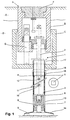
- Fig. 1 shows the view of a road cap with an inner housing B and outer housing C, which are telescopically mounted so that the in the road cap taken up to the earth D and the road surface E to a modified one Elevation of the road surface E is adjustable.
- the street cap is covered by a lid F locked.
- a change in the height of the inner housing B compared to the outer housing C can be achieved by operating a spindle screw G.
- the drive linkage 1 is accommodated in the road cap, which is also telescopic in the embodiment shown.
- the drive linkage essentially comprises a drive device with a key rod 2 and a Axle tube 3, which has a welded-on cover 4 at its upper end square recess 5 and a welded at its lower closed end Square pin 6 has.
- a transverse bore 10 is provided, into which a split pin 11 is inserted.
- this split pin has a shorter length than the inside diameter of the axle tube 3 so that it moves up and down in the axle tube 3 with the key rod 2 can.
- its length is greater than the diagonal of the square recess 5. This has the consequence that the key rod is only pulled out of the axle tube 3 upwards can be until the split pin 11 against the underside of the lid 4 to the system comes.
- the cotter pin 11 is through the opening 12, which is in the lateral surface of the Axle tube 3 is inserted while the key rod 2 is in a suitable Position in which the transverse bore 10 is aligned with the opening 12.
- an outer sleeve tube 13 is provided, which is placed on a tubular bell 14 and in its upper open end an inner Sleeve tube 15 is slidably guided in a reducing sleeve 16.
- the inner sleeve tube is on closed its upper end by means of a PE lid 17.
- the sleeve tubes 13 and 15 prevent soil from reaching the moving parts 3, 7 and 8, but can do not prevent earth movements from putting pressure on these moving parts, which leads to the key rod 2 bending and out of its axial position is moved relative to the square pin 8 at the end of the drive shaft.
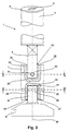
- the coupling sleeve 7 has on its front side Ends 18, 19 recesses 20 and 21, respectively, through floor surfaces 22 and 23 in the depth is limited. While the side surfaces 24, 25 of the recess 20 to the front side 18 diverge, the front and rear run (not visible in FIG. 2) Side surfaces of the recess 20 parallel to each other. The opposite is the case with the recess 21, in which the side surfaces 26, 27 run parallel to one another, while the front and the rear side surface (not visible in FIG. 2) diverge from the end surface 19.
- FIGS. 3 and 4 cuts along the Represent lines III-III and IV-IV through the coupling sleeve 7. From these figures is it can also be seen that the pivoting plane 28 of the square pin 6 to the pivoting plane 29 of the square pin 8 is offset by 90 ° at the end of the drive shaft. Because the side faces 26, 27 almost without play against the side surfaces of the square pin 8 at the end of the drive shaft can be a torque from the sleeve 7 on the square pin 8 on End of the drive shaft. It will also be at the top of the key bar 2 generated torque via the key rod 2, the axle tube 3 and the square pin 6 transferred to the sleeve 7.
- the connections between the Square pin 6, the sleeve 7 and the square pin 8 at the end of the drive shaft as follows manufactured.
- In the sleeve are perpendicular to the axis 30 of the drive linkage 1 provided transverse bores 31, 32, while in the square pin 6 a through transverse bore 33 and in the square pin 8 at the end of the drive shaft a continuous transverse bore 34 is provided.
- the transverse bores 33 and 34 have a larger diameter than the transverse bores 31 and 32.
- One in the bores 31, 33 or 32, 34 inserted split pin 35 or 36 places the square pin 6 or the square pin 8 at the end of the drive shaft 8 in the corresponding recesses 20, 21 swiveling fixed.
Landscapes
- Engineering & Computer Science (AREA)
- General Engineering & Computer Science (AREA)
- Mechanical Engineering (AREA)
- Refuge Islands, Traffic Blockers, Or Guard Fence (AREA)
- Transmission Devices (AREA)
Description
- Fig. 1
- eine schematische Axialschnittansicht durch eine Straßenkappe mit dem erfindungsgemäßen Antriebsgestänge;
- Fig. 2
- eine vergrößerte Darstellung des unteren Teils des erfindungsgemäßen Antriebsgestänges;
- Fig. 3
- eine Schnittansicht entlang der Schnittlinie III-III nach Fig. 2;
- Fig. 4
- eine Schnittansicht entlang der Linie IV-IV nach Fig. 2;
- Fig. 5
- einen Axialschnitt durch ein weiteres Ausführungsbeispiel einer Kupplungsmuffe mit halbzylindermantelförmig ausgebildeten Vierkantzapfen, und
- Fig. 6
- einen Axialschnitt durch ein weiteres Ausführungsbeispiel einer Kupplungsmuffe mit halbkugelförmig ausgebildeten Vierkantzapfen.
- A
- Straßenkappe
- B
- Inneres Gehäuse
- C
- Äußeres Gehäuse
- D
- Erdreich
- E
- Straßendecke
- F
- Deckel
- G
- Spindelschraube
- 1
- Antriebsgestänge
- 2
- Schüsselstange
- 3
- Achsrohr
- 4
- Deckel
- 5
- Ausnehmung
- 6
- Vierkantzapfen
- 7
- Kupplungsmuffe
- 8
- Vierkantzapfen
- 9
- Aggregat
- 10
- Querbohrung
- 11
- Splint
- 12
- Öffnung
- 13
- äußeres Hülsrohr
- 14
- Hülsrohrglocke
- 15
- inneres Hülsrohr
- 16
- Reduzierhülse
- 17
- PE-Deckel
- 18,19
- stirnseitiges Ende
- 20,21
- Ausnehmung
- 22,23
- Bodenfläche
- 24,25
- Seitenflächen
- 26,27
- Seitenflächen
- 28
- Schwenkebene
- 29
- Schwenkebene
- 30
- Achse
- 31,32
- Querbohrung
- 33,34
- Querbohrung
- 35,36
- Splint
- 37
- Spiel
- 38
- Querbohrung
- 39
- Splint
- 40,41
- Stirnfläche
Claims (9)
- Längenjustierbares Antriebsgestänge (1) zur direkten mechanischen Übertragung einer Drehbewegung von einer Betätigungsstelle zu einem entfernt angeordneten anzutreibenden Aggregat (9), insbesondere einem unterirdisch angeordneten Absperrorgan, umfassend eine Antriebseinrichtung (2, 3) mit
einer an der Betätigungsstelle drehbar gelagerten Vierkant-Schlüsselstange (2) und einem zylinderförmigen Achsrohr (3), welches an seiner oberen Stirnseite einen fest verbundenen Deckel (4) mit einem axialen Vierkantdurchbruch (5), an seiner unteren Stirnseite eine fest verbundene Abdeckung und einen mit dieser fest verbundenen, axial nach außen vorstehenden Vierkantzapfen (6) aufweist, sowie
eine Kupplungsmuffe (7) mit axialen Vierkantausnehmungen (20, 21) an beiden Stirnseiten (18, 19), wobei die Seitenflächen der Vierkant-Schlüsselstange (2) zum anzutreibenden Aggregat (9) hin mit den Seitenflächen des Vierkantdurchbruches (5) des Achsrohres (3) in Eingriff stehen und die Vierkant-Schlüsselstange (2) im Vierkantdurchbruch (5) in Längsrichtung verschiebbar ist, und der Vierkantzapfen (6) an der unteren Abdeckung des Achsrohres (3) mit der Vierkantausnehmung (20) an der oberen Stirnseite (18) der Kupplungsmuffe (7) sowie die Vierkantausnehmung (21) an der unteren Stirnseite (19) der Kupplungsmuffe (7) mit einem axial vorstehenden Vierkantzapfen (8) des anzutreibenden Aggregates (9) in Eingriff stehen und mit diesen über in Querbohrungen (31 - 34) in den Vierkantausnehmungen (20, 21) der Kupplungsmuffe (7) und in den Vierkantzapfen (6, 8) eingefügte Splinte (35, 36) verbunden sind, wobei jeweils zwei sich gegenüberliegende Seitenflächen (26, 27) jeder Vierkantausnehmung (20, 21) zueinander parallel und die beiden anderen Seitenflächen (24, 25) nach außen hin divergierend angeordnet sind, wobei die parallelen und divergierenden Seitenflächen (24, 25, 26, 27) der Vierkantausnehmung (20) an der oberen Stirnseite (18) der Kupplungsmuffe (7) relativ zu den parallelen und divergierenden Seitenflächen der Vierkantausnehmung (21) an der unteren Stirnseite (19) der Kupplungsmuffe (7) radial um 90° versetzt angeordnet sind, wobei die Querbohrungen (31, 32) in die Vierkantausnehmungen (20, 21) jeweils parallel zu den divergierenden Seitenflächen eingebracht sind, und wobei die Querbohrungen (33, 34) in den Vierkantzapfen (6, 8) gegenüber den Splintaußenflächen eine Spielpassung (37) aufweisen. - Antriebsgestänge nach Anspruch 1, dadurch gekennzeichnet, dass die Vierkantausnehmungen (20, 21) der Kupplungsmuffe (7) von den Stirnseiten (18, 19) der Kupplungsmuffe (7) zum Inneren der Kupplungsmuffe (7) hin durch jeweilige Bodenflächen (22, 23) in ihrer Tiefe begrenzt sind.
- Antriebsgestänge nach einem der vorhergehenden Ansprüche, dadurch gekennzeichnet, dass die Projektion des jeweiligen Querschnittes der Vierkantzapfen (6, 8) etwa der Bodenfläche (22, 23) der jeweiligen Vierkantausnehmung (20, 21) mit geringem Spiel entspricht.
- Antriebsgestänge nach Anspruch 1, dadurch gekennzeichnet, dass die Querbohrungen (33, 34) in den Vierkantzapfen (6, 8) einen größeren Querschnitt aufweisen als die Querbohrungen (31, 32) in der Kupplungsmuffe (7).
- Antriebsgestänge nach einem der vorhergehenden Ansprüche, dadurch gekennzeichnet, dass die Stirnflächen der Vierkantzapfen (6, 8) gebogen ausgebildet sind.
- Antriebsgestänge nach Anspruch 5, dadurch gekennzeichnet, dass die Stirnflächen (40) der Vierkantzapfen halbzylindermantelförmig ausgebildet sind (Fig.5).
- Antriebsgestänge nach Anspruch 5, dadurch gekennzeichnet, dass die Stirnflächen (41) der Vierkantzapfen halbkugelförmig ausgebildet sind (Fig.6).
- Antriebsgestänge nach den Ansprüchen 6 oder 7, dadurch gekennzeichnet, dass die Zylinderachsen der halbzylindermantelformigen Stirnflächen (40) bzw. die Kugelmittelpunkte der halbkugelförmigen Stirnflächen (41) der Vierkantzapfen in der Achse bzw. der Achsmitte der Querbohrungen (31 bis 34) angeordnet sind, und dass das Spiel (37) der Spielpassungen zwischen den Querbohrungen (33, 34) und den Splintaußenflächen gering ist.
- Antriebsgestänge nach einem der vorhergehenden Ansprüche, dadurch gekennzeichnet, dass sich die Vierkantzapfen (6, 8) mit ihren Stirnflächen auf den Bodenflächen (22, 23) der Vierkantausnehmungen (20, 21) der Kupplungsmuffe (7) abstützen.
Priority Applications (2)
| Application Number | Priority Date | Filing Date | Title |
|---|---|---|---|
| DE59909903T DE59909903D1 (de) | 1999-01-20 | 1999-01-20 | Antriebsgestänge |
| EP19990100958 EP1024307B1 (de) | 1999-01-20 | 1999-01-20 | Antriebsgestänge |
Applications Claiming Priority (1)
| Application Number | Priority Date | Filing Date | Title |
|---|---|---|---|
| EP19990100958 EP1024307B1 (de) | 1999-01-20 | 1999-01-20 | Antriebsgestänge |
Publications (2)
| Publication Number | Publication Date |
|---|---|
| EP1024307A1 EP1024307A1 (de) | 2000-08-02 |
| EP1024307B1 true EP1024307B1 (de) | 2004-07-07 |
Family
ID=8237377
Family Applications (1)
| Application Number | Title | Priority Date | Filing Date |
|---|---|---|---|
| EP19990100958 Expired - Lifetime EP1024307B1 (de) | 1999-01-20 | 1999-01-20 | Antriebsgestänge |
Country Status (2)
| Country | Link |
|---|---|
| EP (1) | EP1024307B1 (de) |
| DE (1) | DE59909903D1 (de) |
Families Citing this family (1)
| Publication number | Priority date | Publication date | Assignee | Title |
|---|---|---|---|---|
| CN116906002B (zh) * | 2023-08-02 | 2025-11-21 | 山东省水工环地质工程有限公司 | 一种地质勘察孔涌水封堵装置 |
Family Cites Families (2)
| Publication number | Priority date | Publication date | Assignee | Title |
|---|---|---|---|---|
| DE194434C (de) * | ||||
| GB972445A (en) * | 1962-05-22 | 1964-10-14 | Eric Walden | Improvements in or relating to universal joints and like couplings |
-
1999
- 1999-01-20 EP EP19990100958 patent/EP1024307B1/de not_active Expired - Lifetime
- 1999-01-20 DE DE59909903T patent/DE59909903D1/de not_active Expired - Lifetime
Also Published As
| Publication number | Publication date |
|---|---|
| DE59909903D1 (de) | 2004-08-12 |
| EP1024307A1 (de) | 2000-08-02 |
Similar Documents
| Publication | Publication Date | Title |
|---|---|---|
| DE102010015064B4 (de) | Feststeller für eine Fahrzeugtür oder -klappe | |
| DE10322265A1 (de) | Kugelgelenkverbindung | |
| DE102019116644A1 (de) | Servolenkeinheit | |
| EP2025474A2 (de) | Kugelgelenk-Abzieher | |
| WO2016188758A1 (de) | Vorrichtung zum verbinden eines kupplungsschafts mit einem wagenkasten eines spurgeführten fahrzeuges | |
| EP0789986B1 (de) | Hubstange für die Dreipunktanbauvorrichtung eines Traktors | |
| EP0581982B1 (de) | Schwenktüre für Kundenführungsanlagen | |
| EP0886034A2 (de) | Bohrvorrichtung | |
| EP1024307B1 (de) | Antriebsgestänge | |
| DE10004257C2 (de) | Betätigungsvorrichtung | |
| DE102009045276A1 (de) | Kugelgelenk | |
| DE3634338A1 (de) | Schnell-kupplungsanordnung | |
| DE20118062U1 (de) | Einbaugarnitur | |
| EP1611363B1 (de) | Umlenkhebel | |
| DE60305288T2 (de) | Gleitdrehlager einer verstellbaren Lenksäule eines Kraftfahrzeuges | |
| DE102021116182A1 (de) | Anhängevorrichtung zur Anbringung an einem Heck eines Fahrzeugs | |
| DE102022122848B3 (de) | Verbindungsklammer sowie Einbaugarnitur | |
| DE19626223A1 (de) | Kellystangen-Bohrvorrichtung | |
| DE3448221C2 (en) | Steering and ignition lock for motor vehicles | |
| DE102020119281A1 (de) | Wellenanordnung und Lenkgetriebe mit einer Wellenanordnung | |
| DE29513664U1 (de) | Antriebsverbindung | |
| DE19947188C2 (de) | Ausziehtisch mit einem Tischgestell | |
| DE3010786C2 (de) | Fernsteuervorrichtung für ein Einstellteil, insbesondere zur Lageverstellung eines Rückspiegels an einem Kraftfahrzeug | |
| DE8809984U1 (de) | Pendeltüre für Kundenführungsanlagen | |
| DE3443712A1 (de) | Lenk- und zuendschloss fuer kraftfahrzeuge |
Legal Events
| Date | Code | Title | Description |
|---|---|---|---|
| PUAI | Public reference made under article 153(3) epc to a published international application that has entered the european phase |
Free format text: ORIGINAL CODE: 0009012 |
|
| 17P | Request for examination filed |
Effective date: 20000127 |
|
| AK | Designated contracting states |
Kind code of ref document: A1 Designated state(s): DE |
|
| AX | Request for extension of the european patent |
Free format text: AL;LT;LV;MK;RO;SI |
|
| AKX | Designation fees paid |
Free format text: DE |
|
| RAP1 | Party data changed (applicant data changed or rights of an application transferred) |
Owner name: TELEKAP GMBH |
|
| 17Q | First examination report despatched |
Effective date: 20030107 |
|
| 111Z | Information provided on other rights and legal means of execution |
Free format text: DE Effective date: 20030926 |
|
| GRAP | Despatch of communication of intention to grant a patent |
Free format text: ORIGINAL CODE: EPIDOSNIGR1 |
|
| GRAS | Grant fee paid |
Free format text: ORIGINAL CODE: EPIDOSNIGR3 |
|
| GRAA | (expected) grant |
Free format text: ORIGINAL CODE: 0009210 |
|
| AK | Designated contracting states |
Kind code of ref document: B1 Designated state(s): DE |
|
| REF | Corresponds to: |
Ref document number: 59909903 Country of ref document: DE Date of ref document: 20040812 Kind code of ref document: P |
|
| PLBE | No opposition filed within time limit |
Free format text: ORIGINAL CODE: 0009261 |
|
| STAA | Information on the status of an ep patent application or granted ep patent |
Free format text: STATUS: NO OPPOSITION FILED WITHIN TIME LIMIT |
|
| 26N | No opposition filed |
Effective date: 20050408 |
|
| PGFP | Annual fee paid to national office [announced via postgrant information from national office to epo] |
Ref country code: DE Payment date: 20180301 Year of fee payment: 20 |
|
| REG | Reference to a national code |
Ref country code: DE Ref legal event code: R071 Ref document number: 59909903 Country of ref document: DE |