EP1024277A2 - Regenerator für ein Stirling Kreislaufsystem - Google Patents
Regenerator für ein Stirling Kreislaufsystem Download PDFInfo
- Publication number
- EP1024277A2 EP1024277A2 EP00101787A EP00101787A EP1024277A2 EP 1024277 A2 EP1024277 A2 EP 1024277A2 EP 00101787 A EP00101787 A EP 00101787A EP 00101787 A EP00101787 A EP 00101787A EP 1024277 A2 EP1024277 A2 EP 1024277A2
- Authority
- EP
- European Patent Office
- Prior art keywords
- regenerator
- based system
- cycle based
- stirling cycle
- resin film
- Prior art date
- Legal status (The legal status is an assumption and is not a legal conclusion. Google has not performed a legal analysis and makes no representation as to the accuracy of the status listed.)
- Granted
Links
- 239000011347 resin Substances 0.000 claims abstract description 57
- 229920005989 resin Polymers 0.000 claims abstract description 57
- 238000007650 screen-printing Methods 0.000 claims abstract description 6
- 238000000016 photochemical curing Methods 0.000 claims abstract description 5
- 230000006835 compression Effects 0.000 claims description 24
- 238000007906 compression Methods 0.000 claims description 24
- 238000004804 winding Methods 0.000 claims description 12
- 238000005304 joining Methods 0.000 claims description 6
- 229920000139 polyethylene terephthalate Polymers 0.000 claims description 6
- 239000005020 polyethylene terephthalate Substances 0.000 claims description 6
- -1 polyethylene terephthalate Polymers 0.000 claims description 5
- 239000004642 Polyimide Substances 0.000 claims description 4
- 239000002184 metal Substances 0.000 claims description 4
- 229920001721 polyimide Polymers 0.000 claims description 4
- 238000003825 pressing Methods 0.000 claims description 4
- 239000007789 gas Substances 0.000 description 56
- 238000009825 accumulation Methods 0.000 description 8
- 238000012546 transfer Methods 0.000 description 6
- 239000006096 absorbing agent Substances 0.000 description 5
- 238000011156 evaluation Methods 0.000 description 4
- 125000006850 spacer group Chemical group 0.000 description 4
- 238000013459 approach Methods 0.000 description 3
- 238000001816 cooling Methods 0.000 description 3
- 238000010586 diagram Methods 0.000 description 3
- 239000000463 material Substances 0.000 description 3
- 238000010521 absorption reaction Methods 0.000 description 2
- 238000011161 development Methods 0.000 description 2
- 238000009826 distribution Methods 0.000 description 2
- 230000017525 heat dissipation Effects 0.000 description 2
- 238000004519 manufacturing process Methods 0.000 description 2
- 230000015572 biosynthetic process Effects 0.000 description 1
- 239000012141 concentrate Substances 0.000 description 1
- 230000000694 effects Effects 0.000 description 1
- 239000001307 helium Substances 0.000 description 1
- 229910052734 helium Inorganic materials 0.000 description 1
- SWQJXJOGLNCZEY-UHFFFAOYSA-N helium atom Chemical compound [He] SWQJXJOGLNCZEY-UHFFFAOYSA-N 0.000 description 1
- 238000000034 method Methods 0.000 description 1
- 238000003856 thermoforming Methods 0.000 description 1
Images


Classifications
-
- F—MECHANICAL ENGINEERING; LIGHTING; HEATING; WEAPONS; BLASTING
- F25—REFRIGERATION OR COOLING; COMBINED HEATING AND REFRIGERATION SYSTEMS; HEAT PUMP SYSTEMS; MANUFACTURE OR STORAGE OF ICE; LIQUEFACTION SOLIDIFICATION OF GASES
- F25B—REFRIGERATION MACHINES, PLANTS OR SYSTEMS; COMBINED HEATING AND REFRIGERATION SYSTEMS; HEAT PUMP SYSTEMS
- F25B43/00—Arrangements for separating or purifying gases or liquids; Arrangements for vaporising the residuum of liquid refrigerant, e.g. by heat
-
- F—MECHANICAL ENGINEERING; LIGHTING; HEATING; WEAPONS; BLASTING
- F02—COMBUSTION ENGINES; HOT-GAS OR COMBUSTION-PRODUCT ENGINE PLANTS
- F02G—HOT GAS OR COMBUSTION-PRODUCT POSITIVE-DISPLACEMENT ENGINE PLANTS; USE OF WASTE HEAT OF COMBUSTION ENGINES; NOT OTHERWISE PROVIDED FOR
- F02G1/00—Hot gas positive-displacement engine plants
- F02G1/04—Hot gas positive-displacement engine plants of closed-cycle type
- F02G1/043—Hot gas positive-displacement engine plants of closed-cycle type the engine being operated by expansion and contraction of a mass of working gas which is heated and cooled in one of a plurality of constantly communicating expansible chambers, e.g. Stirling cycle type engines
- F02G1/053—Component parts or details
- F02G1/057—Regenerators
Definitions
- the present invention relates to a regenerator for use in a Stirling refrigerator, i.e. a refrigerator based on the principle of the Stirling cycle, for the purpose of accumulating the heat of working gas.
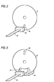
- Figs. 1 and 2 show a conventional regenerator designed for use in a Stirling cycle based system.
- This regenerator 1 is produced by forming irregularities on the surface of a resin film 2 by bonding a plurality of extra-fine spacers 4 at regular intervals and parallel to one another, and then winding the resin film 2 up into a cylindrical shape.
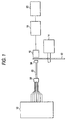
- Fig. 3 shows an example of a Stirling refrigerator of a free piston type provided with a regenerator 1 as described just above.
- This Stirling refrigerator has a cylinder 8 filled with working gas such as helium, a piston 5 and a displacer 7 for dividing the space inside the cylinder 8 into a compression space 9 and an expansion space 10, a linear motor 6 for driving the reciprocating movement of the piston 5, plate springs 11 and 12 for supporting the piston 5 and the displacer 7 in such a way as to permit, by resilience, their reciprocating movement, a heat absorber 14 provided at the expansion space 10 so as to absorb heat from the outside, and a heat dissipater 13 provided at the compression space 9 so as to dissipate heat to the outside.
- working gas such as helium
- a piston 5 and a displacer 7 for dividing the space inside the cylinder 8 into a compression space 9 and an expansion space 10
- a linear motor 6 for driving the reciprocating movement of the piston 5
- plate springs 11 and 12 for supporting
- Reference numeral 15 represents a heat exchanger for heat dissipation
- reference numeral 16 represents a heat exchanger for heat absorption. These heat exchangers serve to prompt the exchange of heat between the inside and the outside, and the regenerator 1 is arranged between these exchangers.
- a predetermined phase difference is kept between the reciprocating movement of the displacer 7 and that of the piston 5.
- the displacer 7 moves downward, the working gas inside the expansion space 10 expands.
- heat is absorbed from the outside air through the heat absorber 14 and then through the heat-absorption heat exchanger 16, and thus the working gas is heated, achieving isothermal expansion.
- the displacer 7 starts moving upward, the working gas inside the expansion space 10 is transferred through the regenerator 1 back to the compression space 9.
- the heat that has previously been accumulated in the regenerator 1 is transferred to the working gas, causing the temperature of the working gas to rise.
- This sequence of events called the Stirling cycle, is repeated by the reciprocating movement of the piston 5 and the displacer 7, and, as a result, heat is steadily absorbed through the heat absorber 14 and transferred to the working gas, gradually cooling the absorber 14.
- An object of the present invention is to provide an inexpensive regenerator for use in a Stirling cycle based system by simplifying the production process thereof.
- Another object of the present invention is to achieve satisfactorily high heat accumulation performance.
- a regenerator for use in a Stirling cycle based system such as is arranged between a compression space and an expansion space of the Stirling cycle based system so as to serve as a flow passage for working gas transferred back and forth between the compression space and the expansion space and simultaneously serve to accumulate the heat of the working gas, is produced by forming a plurality of ribs integrally on a surface of a resin film and winding the resin film up into a cylindrical shape.
- a regenerator for use in a Stirling cycle based system such as is arranged between a compression space and an expansion space of the Stirling cycle based system so as to serve as a flow passage for working gas transferred back and forth between the compression space and the expansion space and simultaneously serve to accumulate the heat of the working gas, is produced by joining together two or more cores in the direction of the axes of the cores.
- the cores are each produced by forming a plurality of ribs integrally on a surface of a resin film and winding the resin film up into a cylindrical shape.
- a regenerator for use in a Stirling cycle based system such as is arranged between a compression space and an expansion space of the Stirling cycle based system so as to serve as a flow passage for working gas transferred back and forth between the compression space and the expansion space and simultaneously serve to accumulate the heat of the working gas, is produced by forming a plurality of ribs integrally on both surfaces of a resin film and winding the resin film up into a cylindrical shape.
- the ribs are inclined relative to the axis of the regenerator.
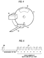
- FIG. 5 is a perspective view of the regenerator, for use in a Stirling cycle based system, of the first embodiment
- Fig. 6 is an enlarged view of a principal portion thereof.
- This regenerator 1 is produced by winding up a resin film 2 into a cylindrical shape.
- a plurality of ribs 3 are formed integrally with the resin film 2 at regular intervals and parallel to the axis of the regenerator 1.
- the resin film 2 is preferably made of a material having high specific heat, low heat conductivity, high heat resistance, low moisture absorbency, and other desirable properties, for example polyethylene terephthalate (PET), a polyimide, or the like.
- PET polyethylene terephthalate
- the ribs 3 are preferably formed, for example, by applying photo-curing ink to the surface of the resin film 2 and then applying screen printing thereto, or by pressing a heated metal mold against the surface of the resin film 2 (a thermoforming process).
- the regenerator 1 of this embodiment employs a resin film 2 having ribs 3 formed integrally on the surface thereof, and thus can be produced at lower cost and with more ease than a conventional regenerator that requires the bonding of spacers.
- FIG. 7 is a perspective view of the regenerator, for use in a Stirling cycle based system, of the second embodiment.
- This regenerator 1 is produced by joining together three cylinder-shaped regenerator cores 1a, 1b, and 1c of identical size in the direction of the axes thereof.
- the regenerator cores 1a, 1b, and 1c are each produced by forming a plurality of ribs 3 integrally on the surface of a resin film 2 at regular intervals and parallel to the axis of the core and then winding up the resin film 2 into a cylindrical shape.
- the ribs 3 are formed at the same intervals in all of the regenerator cores 1a, 1b, and 1c.
- the regenerator 1 of this embodiment is produced by joining together shorter regenerator cores 1a, 1b, and 1c, and therefore some of the ribs 3 are left discontinuous between adjacent cores.
- the working gas flowing from the direction indicated by an arrow 20 and then passing between the ribs 3 of the regenerator core 1c, flows into the regenerator core 1b, it collides with the ribs 3 of the regenerator core 1b and thereby its flow is disturbed.
- boundary layers are cut off before developing. The same occurs when the working gas passes from the regenerator core 1b to the regenerator core 1a.
- the regenerator 1 of this embodiment offers much higher heat accumulation performance than a conventional regenerator or the regenerator of the first embodiment where the regenerator 1 is composed of a single core.
- the resin film 2 can be mass-produced with minimal variations in performance among the regenerator cores 1a, 1b, and 1c.
- regenerator 1 is composed of three regenerator cores 1a, 1b, and 1c, it is also possible to use more regenerator cores in expectation of still higher heat accumulation performance.
- FIG. 8 is a perspective view of the regenerator, for use in a Stirling cycle based system, of the third embodiment.
- This regenerator 1 is produced, as in the second embodiment, by joining together three cylinder-shaped regenerator cores 1a, 1b, and 1c of identical size in the direction of the axes thereof.
- the regenerator 1 at its end on the regenerator core 1a side, communicates with the expansion space 10 (see Fig. 3), and, at its end on the regenerator core 1c side, communicates with the compression space 9 (see Fig. 3).
- a plurality of ribs 3 are formed integrally at regular intervals and parallel to the axis thereof. These ribs 3 are formed at intervals that increase stepwise toward the expansion space 10; that is, they are formed at longer intervals in the regenerator core 1b than in the regenerator core 1c, and at longer intervals in the regenerator core 1a than in the regenerator core 1b.
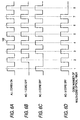
- FIG. 9 is a perspective view of the regenerator, for use in a Stirling cycle based system, of the fourth embodiment, and Fig. 10 is an enlarged view of a principal portion thereof.
- This regenerator 1 is produced by winding up a resin film 2 into a cylindrical shape.
- a plurality of top-side ribs (indicated by solid lines 3a in Fig. 9) and a plurality of back-side ribs (indicated by dotted lines 3b in Fig. 9), respectively, are formed integrally at regular intervals and parallel to one another.
- top-side ribs 3a and the back-side ribs 3b are inclined in opposite directions relative to the axis of the regenerator 1.
- overlapping turns thereof make contact with one another at the intersections between the top-side ribs 3a of one turn and the back-side ribs 3b of another, and this helps secure gaps that serve as flow passages for the working gas.
- the regenerator 1 of this embodiment offers stable heat accumulation performance with almost no variations.
- a resin film having the above-listed specifications was wound up into a cylindrical shape to produce a regenerator for use in a Stirling cycle based system.
- This regenerator was fitted inside the cylinder of a Stirling refrigerator, and the working gas was transferred back and forth between the compression space and the expansion space at varying reciprocating flow rates G (L/m) to determine the regenerator efficiency ⁇ .
- G reciprocating flow rates
- the regenerator efficiency ⁇ takes a value within the following range: 0 ⁇ ⁇ ⁇ 1
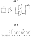
- Fig. 12 shows the result of the performance evaluation described above.
- reference numeral 30 indicates a graph of the regenerator efficiency of a regenerator that adopts a structure according to the present invention
- reference numeral 31 indicates a graph of the regenerator efficiency of a regenerator that adopts a conventional structure.
- the regenerator that adopts a structure according to the present invention offers higher regenerator efficiency and thus higher heat accumulation performance than the regenerator that adopts a conventional structure.
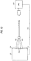
- FIG. 13 is a perspective view of the regenerator, for use in a Stirling cycle based system, of the fifth embodiment.
- This regenerator 1 is produced by winding up a resin film 2 into a cylindrical shape. With respect to the direction of the flow of the working gas indicated by an arrow 20, the regenerator 1, at its upstream-side end, communicates with the compression space 9 (see Fig. 3) and, at its downstream-side end, communicates with the expansion space 10 (see Fig. 3).
- top-side ribs 3a and a plurality of back-side ribs 3b are formed integrally at regular intervals and parallel to one another.
- the top-side ribs 3a and the back-side ribs 3b are inclined in opposite directions relative to the axis of the regenerator 1.
- the top-side ribs 3a and the back-side ribs 3b are formed, relative to the axis, at inclination angles that decrease stepwise toward the end at which the regenerator 1 communicates with the expansion space 10.
Landscapes
- Engineering & Computer Science (AREA)
- Chemical & Material Sciences (AREA)
- Mechanical Engineering (AREA)
- General Engineering & Computer Science (AREA)
- Combustion & Propulsion (AREA)
- Analytical Chemistry (AREA)
- Power Engineering (AREA)
- Physics & Mathematics (AREA)
- Thermal Sciences (AREA)
- Heat-Exchange Devices With Radiators And Conduit Assemblies (AREA)
- Printing Methods (AREA)
- Laminated Bodies (AREA)
Applications Claiming Priority (2)
| Application Number | Priority Date | Filing Date | Title |
|---|---|---|---|
| JP02132199A JP3583637B2 (ja) | 1999-01-29 | 1999-01-29 | スターリング機関用再生器 |
| JP2132199 | 1999-01-29 |
Publications (4)
| Publication Number | Publication Date |
|---|---|
| EP1024277A2 true EP1024277A2 (de) | 2000-08-02 |
| EP1024277A3 EP1024277A3 (de) | 2001-06-27 |
| EP1024277A9 EP1024277A9 (de) | 2004-09-08 |
| EP1024277B1 EP1024277B1 (de) | 2005-03-30 |
Family
ID=12051901
Family Applications (1)
| Application Number | Title | Priority Date | Filing Date |
|---|---|---|---|
| EP00101787A Expired - Lifetime EP1024277B1 (de) | 1999-01-29 | 2000-01-28 | Regenerator für ein Stirling-Kreislaufsystem |
Country Status (5)
| Country | Link |
|---|---|
| US (1) | US6474075B1 (de) |
| EP (1) | EP1024277B1 (de) |
| JP (1) | JP3583637B2 (de) |
| KR (1) | KR100352961B1 (de) |
| DE (1) | DE60019006T2 (de) |
Families Citing this family (15)
| Publication number | Priority date | Publication date | Assignee | Title |
|---|---|---|---|---|
| JP3690980B2 (ja) * | 2000-11-30 | 2005-08-31 | シャープ株式会社 | スターリング機関 |
| JP2002295914A (ja) * | 2001-03-30 | 2002-10-09 | Ekuteii Kk | シート型蓄冷材およびその製造方法、並びにそれを使用した蓄冷器および冷凍機 |
| US6854509B2 (en) * | 2001-07-10 | 2005-02-15 | Matthew P. Mitchell | Foil structures for regenerators |
| JP2003065620A (ja) * | 2001-08-22 | 2003-03-05 | Sharp Corp | スターリング機械用再生器、それを用いたスターリング冷凍機及び流動ガスの熱再生システム |
| US6694730B2 (en) * | 2002-05-30 | 2004-02-24 | Superconductor Technologies, Inc. | Stirling cycle cryocooler with improved magnet ring assembly and gas bearings |
| KR20040033764A (ko) * | 2002-10-15 | 2004-04-28 | 주명자 | 스털링사이클계 재생기 |
| DE60320681T2 (de) * | 2002-10-31 | 2009-06-10 | Sharp K.K. | Regenerator, verfahren zur herstellung des regenerators, system zur herstellung des regenerators und stirling-kältemaschine |
| US6688113B1 (en) * | 2003-02-11 | 2004-02-10 | Superconductor Technologies, Inc. | Synthetic felt regenerator material for stirling cycle cryocoolers |
| US20050056036A1 (en) * | 2003-09-17 | 2005-03-17 | Superconductor Technologies, Inc. | Integrated cryogenic receiver front-end |
| US8096118B2 (en) | 2009-01-30 | 2012-01-17 | Williams Jonathan H | Engine for utilizing thermal energy to generate electricity |
| LT5969B (lt) | 2012-03-09 | 2013-11-25 | Uab "Modernios E-Technologijos" | Daugiacilindrio stirlingo ciklo įrenginio tiesioginės šilumokaitos regeneratorius |
| US20140264979A1 (en) * | 2013-03-13 | 2014-09-18 | Transitions Opticals, Inc. | Method of preparing photochromic-dichroic films having reduced optical distortion |
| US20140265010A1 (en) * | 2013-03-13 | 2014-09-18 | Transitions Optical, Inc. | Method of preparing photochromic-dichroic films having reduced optical distortion |
| JP6386230B2 (ja) * | 2014-02-03 | 2018-09-05 | 東邦瓦斯株式会社 | 熱音響装置用の蓄熱器 |
| EP3117090A1 (de) * | 2014-03-12 | 2017-01-18 | NV Bekaert SA | Regenerator für einen wärmetaktmotor |
Family Cites Families (8)
| Publication number | Priority date | Publication date | Assignee | Title |
|---|---|---|---|---|
| NL6401013A (de) | 1964-02-07 | 1965-08-09 | ||
| GB1354502A (en) | 1970-08-28 | 1974-06-05 | Ici Ltd | Heat exchangers |
| JPS62177186A (ja) * | 1986-01-29 | 1987-08-04 | Ishikawajima Harima Heavy Ind Co Ltd | プレ−トフイン型熱交換器の製造方法 |
| US4866943A (en) * | 1988-10-17 | 1989-09-19 | Cdc Partners | Cyrogenic regenerator |
| GB9104156D0 (en) | 1991-02-27 | 1991-04-17 | Rolls Royce & Ass | Heat exchanger |
| US5429177A (en) * | 1993-07-09 | 1995-07-04 | Sierra Regenators, Inc. | Foil regenerator |
| US5445216A (en) | 1994-03-10 | 1995-08-29 | Cannata; Antonio | Heat exchanger |
| BE1011595A3 (nl) | 1997-12-09 | 1999-11-09 | Ewa Nova Bvba Besloten Vennoot | Verbeterde warmtewisselaar en werkwijze voor het verwezenlijken van zulke warmtewisselaar. |
-
1999
- 1999-01-29 JP JP02132199A patent/JP3583637B2/ja not_active Expired - Fee Related
-
2000
- 2000-01-12 US US09/481,395 patent/US6474075B1/en not_active Expired - Fee Related
- 2000-01-28 DE DE60019006T patent/DE60019006T2/de not_active Expired - Lifetime
- 2000-01-28 KR KR1020000004160A patent/KR100352961B1/ko not_active Expired - Fee Related
- 2000-01-28 EP EP00101787A patent/EP1024277B1/de not_active Expired - Lifetime
Non-Patent Citations (1)
| Title |
|---|
| None |
Also Published As
| Publication number | Publication date |
|---|---|
| DE60019006T2 (de) | 2006-03-30 |
| EP1024277A3 (de) | 2001-06-27 |
| EP1024277A9 (de) | 2004-09-08 |
| JP3583637B2 (ja) | 2004-11-04 |
| DE60019006D1 (de) | 2005-05-04 |
| EP1024277B1 (de) | 2005-03-30 |
| KR20000053649A (ko) | 2000-08-25 |
| JP2000220897A (ja) | 2000-08-08 |
| KR100352961B1 (ko) | 2002-09-18 |
| US6474075B1 (en) | 2002-11-05 |
Similar Documents
| Publication | Publication Date | Title |
|---|---|---|
| EP1024277B1 (de) | Regenerator für ein Stirling-Kreislaufsystem | |
| CN215177134U (zh) | 板式散热器及板式散热装置 | |
| US20100299924A1 (en) | Involute Foil Regenerator | |
| US6779342B2 (en) | Stirling engine | |
| EP1422484B1 (de) | Regenerator und regenerativ-wärmesystem für fluidisiertes gas unter verwendung des regenerators | |
| CN210070062U (zh) | 一种散热器、空调室外机和空调器 | |
| JPH0566095A (ja) | 熱接続装置とその製造方法 | |
| KR102682206B1 (ko) | 진동형 히트 파이프 기반 배터리 냉각 모듈 및 이를 포함하는 배터리 유닛 | |
| JP2003166766A (ja) | パルス管冷凍機の熱交換器 | |
| JP2004132696A (ja) | スターリング機関用再生器 | |
| JP3563679B2 (ja) | スターリング冷凍機用熱交換器及び熱交換器体 | |
| KR100391948B1 (ko) | 스터링기기의 열교환기 구조 | |
| JP3263566B2 (ja) | スターリング機器のギャップ式熱交換器 | |
| CN113994158B (zh) | 蓄热器的制造方法 | |
| KR20060045109A (ko) | 극저온 냉각기의 재생기 및 그 제조방법과 이를 이용한극저온 냉동기 | |
| JPH1194481A (ja) | 熱交換器用チューブおよび熱交換器 | |
| JP3366521B2 (ja) | 熱交換器及びその製造方法 | |
| JP2003028527A (ja) | スターリング機関用内部熱交換器及びスターリング冷凍機 | |
| JP2006207851A (ja) | 再生器およびその製造方法ならびにスターリング機関、スターリング冷却庫 | |
| JPH09310929A (ja) | 外燃式熱ガス機関の再生器 | |
| JPH09113047A (ja) | スターリング機器 | |
| KR20000014367A (ko) | 스터링기기의 열교환기 | |
| HK1086878B (en) | Involute foil regenerator |
Legal Events
| Date | Code | Title | Description |
|---|---|---|---|
| PUAI | Public reference made under article 153(3) epc to a published international application that has entered the european phase |
Free format text: ORIGINAL CODE: 0009012 |
|
| AK | Designated contracting states |
Kind code of ref document: A2 Designated state(s): DE FR GB SE |
|
| AX | Request for extension of the european patent |
Free format text: AL;LT;LV;MK;RO;SI |
|
| PUAL | Search report despatched |
Free format text: ORIGINAL CODE: 0009013 |
|
| AK | Designated contracting states |
Kind code of ref document: A3 Designated state(s): AT BE CH CY DE DK ES FI FR GB GR IE IT LI LU MC NL PT SE |
|
| AX | Request for extension of the european patent |
Free format text: AL;LT;LV;MK;RO;SI |
|
| RIC1 | Information provided on ipc code assigned before grant |
Free format text: 7F 02G 1/057 A, 7F 28D 9/04 B |
|
| 17P | Request for examination filed |
Effective date: 20010905 |
|
| AKX | Designation fees paid |
Free format text: DE FR GB SE |
|
| RBV | Designated contracting states (corrected) |
Designated state(s): DE FR GB SE |
|
| GRAP | Despatch of communication of intention to grant a patent |
Free format text: ORIGINAL CODE: EPIDOSNIGR1 |
|
| GRAS | Grant fee paid |
Free format text: ORIGINAL CODE: EPIDOSNIGR3 |
|
| GRAA | (expected) grant |
Free format text: ORIGINAL CODE: 0009210 |
|
| AK | Designated contracting states |
Kind code of ref document: B1 Designated state(s): DE FR GB SE |
|
| REG | Reference to a national code |
Ref country code: GB Ref legal event code: FG4D |
|
| REF | Corresponds to: |
Ref document number: 60019006 Country of ref document: DE Date of ref document: 20050504 Kind code of ref document: P |
|
| REG | Reference to a national code |
Ref country code: SE Ref legal event code: TRGR |
|
| ET | Fr: translation filed | ||
| PLBE | No opposition filed within time limit |
Free format text: ORIGINAL CODE: 0009261 |
|
| STAA | Information on the status of an ep patent application or granted ep patent |
Free format text: STATUS: NO OPPOSITION FILED WITHIN TIME LIMIT |
|
| 26N | No opposition filed |
Effective date: 20060102 |
|
| PGFP | Annual fee paid to national office [announced via postgrant information from national office to epo] |
Ref country code: SE Payment date: 20091218 Year of fee payment: 11 |
|
| PGFP | Annual fee paid to national office [announced via postgrant information from national office to epo] |
Ref country code: FR Payment date: 20100208 Year of fee payment: 11 |
|
| PGFP | Annual fee paid to national office [announced via postgrant information from national office to epo] |
Ref country code: GB Payment date: 20100202 Year of fee payment: 11 Ref country code: DE Payment date: 20100121 Year of fee payment: 11 |
|
| REG | Reference to a national code |
Ref country code: SE Ref legal event code: EUG |
|
| GBPC | Gb: european patent ceased through non-payment of renewal fee |
Effective date: 20110128 |
|
| REG | Reference to a national code |
Ref country code: FR Ref legal event code: ST Effective date: 20110930 |
|
| PG25 | Lapsed in a contracting state [announced via postgrant information from national office to epo] |
Ref country code: FR Free format text: LAPSE BECAUSE OF NON-PAYMENT OF DUE FEES Effective date: 20110131 |
|
| PG25 | Lapsed in a contracting state [announced via postgrant information from national office to epo] |
Ref country code: GB Free format text: LAPSE BECAUSE OF NON-PAYMENT OF DUE FEES Effective date: 20110128 |
|
| REG | Reference to a national code |
Ref country code: DE Ref legal event code: R119 Ref document number: 60019006 Country of ref document: DE Effective date: 20110802 |
|
| PG25 | Lapsed in a contracting state [announced via postgrant information from national office to epo] |
Ref country code: SE Free format text: LAPSE BECAUSE OF NON-PAYMENT OF DUE FEES Effective date: 20110129 |
|
| PG25 | Lapsed in a contracting state [announced via postgrant information from national office to epo] |
Ref country code: DE Free format text: LAPSE BECAUSE OF NON-PAYMENT OF DUE FEES Effective date: 20110802 |