EP1024108A1 - Dispositif de contrôle de déplacement d'une structure portante d'engin roulant - Google Patents
Dispositif de contrôle de déplacement d'une structure portante d'engin roulant Download PDFInfo
- Publication number
- EP1024108A1 EP1024108A1 EP00400096A EP00400096A EP1024108A1 EP 1024108 A1 EP1024108 A1 EP 1024108A1 EP 00400096 A EP00400096 A EP 00400096A EP 00400096 A EP00400096 A EP 00400096A EP 1024108 A1 EP1024108 A1 EP 1024108A1
- Authority
- EP
- European Patent Office
- Prior art keywords
- rotation
- axes
- axis
- axle
- machine
- Prior art date
- Legal status (The legal status is an assumption and is not a legal conclusion. Google has not performed a legal analysis and makes no representation as to the accuracy of the status listed.)
- Granted
Links
- 239000003381 stabilizer Substances 0.000 claims description 16
- 238000005096 rolling process Methods 0.000 claims description 12
- 238000006073 displacement reaction Methods 0.000 claims description 4
- 239000007787 solid Substances 0.000 abstract 1
- 241000288140 Gruiformes Species 0.000 description 4
- 230000005540 biological transmission Effects 0.000 description 4
- 238000009434 installation Methods 0.000 description 3
- 239000000725 suspension Substances 0.000 description 3
- 230000001154 acute effect Effects 0.000 description 2
- 230000000694 effects Effects 0.000 description 2
- 230000002706 hydrostatic effect Effects 0.000 description 2
- 241001417527 Pempheridae Species 0.000 description 1
- 235000003434 Sesamum indicum Nutrition 0.000 description 1
- 244000000231 Sesamum indicum Species 0.000 description 1
- 229910000746 Structural steel Inorganic materials 0.000 description 1
- 241000897276 Termes Species 0.000 description 1
- 238000012550 audit Methods 0.000 description 1
- 238000005452 bending Methods 0.000 description 1
- 210000000988 bone and bone Anatomy 0.000 description 1
- 230000005484 gravity Effects 0.000 description 1
- 230000009347 mechanical transmission Effects 0.000 description 1
- 238000000034 method Methods 0.000 description 1
- 210000000056 organ Anatomy 0.000 description 1
- 230000003071 parasitic effect Effects 0.000 description 1
- 238000011084 recovery Methods 0.000 description 1
- 230000035939 shock Effects 0.000 description 1
- 125000006850 spacer group Chemical group 0.000 description 1
- 230000000007 visual effect Effects 0.000 description 1
Images


Classifications
-
- B—PERFORMING OPERATIONS; TRANSPORTING
- B66—HOISTING; LIFTING; HAULING
- B66F—HOISTING, LIFTING, HAULING OR PUSHING, NOT OTHERWISE PROVIDED FOR, e.g. DEVICES WHICH APPLY A LIFTING OR PUSHING FORCE DIRECTLY TO THE SURFACE OF A LOAD
- B66F9/00—Devices for lifting or lowering bulky or heavy goods for loading or unloading purposes
- B66F9/06—Devices for lifting or lowering bulky or heavy goods for loading or unloading purposes movable, with their loads, on wheels or the like, e.g. fork-lift trucks
- B66F9/065—Devices for lifting or lowering bulky or heavy goods for loading or unloading purposes movable, with their loads, on wheels or the like, e.g. fork-lift trucks non-masted
- B66F9/0655—Devices for lifting or lowering bulky or heavy goods for loading or unloading purposes movable, with their loads, on wheels or the like, e.g. fork-lift trucks non-masted with a telescopic boom
Definitions
- the invention relates to the technical field of self-propelled machines of lifting and handling.
- the invention relates more particularly to handling carts.
- the mast or the telescopic boom can be adjustable.
- Such carriages include a cabin containing the driving position and a powertrain, located on either side of the telescopic arm, the axis substantially horizontal articulation of the arm being placed as low as possible to improve lateral visibility of the operator when the arm is in position lowered.
- the invention relates more particularly, but not exclusively, to self-propelled trucks with improved visibility for the driver, of the type shown above.
- devices for slope correction are generally provided, these devices making it possible to rotate the carriage frame relative to a longitudinal direction.
- These superelevation correction devices conventionally include at minus a double-acting cylinder, movable relative to the chassis of the carriage around of a substantially longitudinal and movable axis relative to a front axle or rear of the carriage along an axis formed at the end of the piston of the double cylinder effect.
- Document US-4 679 803 describes a device for modifying the center effective gravity of a mobile land vehicle having an oscillating assembly.
- the device according to document US-4 679 803 also makes it possible to maintain the cabin of the assembly oscillating in a substantially horizontal plane on sloping grounds.
- the device comprises, between a platform and a frame arranged on the vehicle tracks, four non-parallel connections and four cylinders.
- These links are connected to the platform and the frame by multi-directional links. They are inclined at an acute angle open upwards by compared to the vertical.
- the four cylinders connect the links two by two and form an acute angle with the horizontal axis of the vehicle.
- Such a device has the disadvantage of requiring many parts in movement and friction, which promotes wear.
- the object of the invention is to propose a device making it possible to remedy the disadvantages of the cited prior art.
- the invention relates to a device allowing control single, manual or automatic, of the two correction movements of cant and lateral offset, these two movements can be used functionally independently of each other.
- the invention relates, according to a first aspect to a suitable device controlling the relative movement of the pivoting structure of a rolling vehicle relative to an axle of said machine, the device comprising a rigid frame integral with said axle, this rigid frame being articulated to the bearing structure of the machine, control means allowing the rotation of the horizontal plane means of the carrying structure of the machine with respect to the mean horizontal plane rigid frame integral with said axle, said axle not being directly attached to the supporting structure of the machine
- each link is provided with a body with two axes of parallel rotation, each upper axis of rotation corresponding to an axis of rotation of the rods relative to the bearing structure, and each lower axis of rotation corresponding to an axis of rotation of the beams with respect to links.
- the spacing of the upper axes of rotation of the rods is greater than the spacing of the lower axes of rotation of these links, these links being inclined at an angle ⁇ open upwards with respect to the median plane P of the bearing structure of the machine, when the two planes defined by the axes upper and lower are parallel.
- the angle ⁇ is between a few degrees and about 30 degrees.
- the means for controlling the movement of the rigid frame relative to the supporting structure of the machine include a single cylinder articulated in rotation about an axis substantially parallel to the upper articulation axes of the rods, the single cylinder being articulated in rotation about a lower axis substantially parallel to the lower articulation axes of the rods.
- the cylinder is tilted at an angle ⁇ between a few degrees and 60 degrees by relation to the mean plane of the supporting structure, when the two planes defined by the high and low articulation axes of the links are parallel.
- the device is attached by assembly to a supporting structure or chassis conventional, in one embodiment.
- the device is arranged on the extreme front part of the supporting structure of a rolling machine.
- the invention relates according to a second aspect, to a rolling vehicle provided at least one device as defined below.
- the machine comprises, in one embodiment, a front axle and a rear axle with wheels driving and directing.
- FIGS. 1 to 16 taken successively, are given in order ensure, in addition to the description, an easy understanding of a embodiment of the invention and illustrate only one possible succession steps for mounting a device according to the invention, in no way limiting.
- FIG. 1 a chassis 1 produced in the form of a self-supporting beam.
- the chassis 1 can be of more traditional design and include for example a rigid frame in bending and twisting formed of side members, crosspieces and spacers.
- the chassis in the form of a box beam shown in FIG. 1 can be, as the case if necessary, assembled by tenons and mortise.
- the chassis shown in Figure 1 has, on its lateral flanks substantially vertical 2, 3 of the openings 4.
- openings 4 can allow the passage of the control hoses electric, hydraulic, or pneumatic of the various organs of the handling.
- mechanical transmission members can pass to the through openings 4.
- the chassis box beam can contain part of the control relays, mechanical or hydrostatic transmission means and ensuring relative protection of these elements against shocks.
- the chassis comprises at the rear part, a hinge pin 5 substantially horizontal for the lifting arm.
- the lifting arm is not not only articulated in rotation along a horizontal axis relative to the chassis but can also rotate relative to the chassis along an axis substantially vertical.
- the horizontal axis of inclination of the arm can be mounted on a flat rotatable in relation to the chassis and assembled on top of it, as it is practiced for mobile cranes.
- the horizontal lifting or latching axis of the arm is supported by a turret located at the rear end of the chassis and movable relative to this chassis around an axis substantially perpendicular to the pivot axis of the arm.
- the chassis has, at the front end, two pairs of pin holes 6, 7, arranged symmetrically with respect to the median vertical plane P to the chassis 1.
- Each pair of axis holes 6, 7 defines an axis 8, 9 of articulation, the two axes 8, 9 being parallel.
- the front end of the chassis has a general shape of an open U down, when viewed from the side.
- the base of this U is formed by a substantially planar sheet 10 whose width I 10 is greater than the average width of the box beam.
- Flanges 11, 12, substantially perpendicular to the sheet 10 form the substantially parallel branches of the U and support, laterally, the holes axis 6, 7.
- a hinge pin 13 of the jack is defined by two supports 14, 15 projecting from the sheet 10, downwards.
- axis 13 can be located on one side or the other of the median plane P of the chassis, as will appear later.
- the axis 13 is placed on the left side of the plane P when the chassis is seen from the front.
- the axis 13 is parallel to the articulation axes 8, 9 defined above and is placed below the plane R containing these axes 8, 9.
- the supports 14, 15 are rigidly assembled to the sheet 10 in a position such that the median plane P 'to the supports 14, 15 is substantially vertical and at length L 10 of the part of the sheet 10 which projects laterally from both sides. another of the box beam.
- the lower front part of the box beam has a semi-arc shape 16 open downwards for the passage of the front deck, as it will appear by the after.
- Two rods 17, 18 are mounted mobile in rotation around the axes hinge 8, 9.
- each link 17, 18 is provided with a body 19 in two axes of rotation 20, 21 parallel, the upper axis 20 being associated with the holes axes 6, 7, the lower axis 21 being associated with the subframe, as will be described more fully below.
- each upper axis 20 corresponds to an axis (8,9).
- the body 19 of the rods can be pierced with a through hole 22, elliptical in the embodiment shown.
- the lower axes 21 of the rods 17, 18 are mounted movable in rotation relative to a subframe 23.
- each lower axis 21 of the links 17, 18 corresponds to an axis 29, 30.
- this angle a is substantially equal to 10 degrees.
- the first flange 25, the second flange 27 and, where appropriate, the parts articulation 24 of the stabilizers are supported by two beams 31, 32 parallel, of circular section in the embodiment shown.
- These beams 31, 32 are spaced apart by a width substantially equal to that separating the axes 8, 9 of the upper articulation of the links 17, 18.
- the first flange 25 has, in front view, a general form of bone, the middle part being narrower than the two extreme parts.
- the first flange 25 is substantially symmetrical relative to a plane median perpendicular to the large faces of this flange.
- the subframe 23 comprises in rear part two angles 33 of U-shaped section open towards the rear.
- Each angle iron 33 has two support and assembly walls 34, 35, parallel and forming the branches of the U-section, these walls being perpendicular to the second flange 27.
- a third flange 36, substantially parallel to the first and second flange 25, 27 is interposed between these first and second flanges 25, 27 and comes to form the base of the U-shaped profiles of the two lateral angles 33.
- the two lateral angles 33 are intended for assembling the front axle to the subframe as shown in Figures 9 and following.
- one of the beams 31, 32 of the subframe 23 is provided with an axle support 37, 38, projecting, for the lower articulation of the control jack shown in Figures 7, 8 especially.
- the axis of articulation upper 13 of the control cylinder can be arranged on one side or the other of the median plane P.
- the lower articulation axis 39 of the control cylinder defined by the protruding parts 37, 38 on one of the beams 31, 32 of the subframe can be arranged on one side or the other of the median plane P ''.
- the axis 13 is to the left of the plane P and the axis 39 to the right of plane P '' when the subframe and the chassis are seen from the front.
- axis 13 could be to the right of the plane P and the axis 39 to left of plane P '' when the subframe 23 and the chassis 1 are seen from the front.
- control cylinder 40 is inclined relative to the plans P and P ''.
- the cylinder 40 is inclined at an angle ⁇ of the order 55 degrees from planes P and P ', or about 35 degrees from to the R and R 'planes.
- a conventional front axle is associated with the chassis via the false chassis 23.
- the front axle i.e. the axle which connects the two driving front wheels and which supports steering pivots is therefore not directly attached to the chassis by the front suspension elements.
- the articulation part 24 of the stabilizers arranged, where appropriate, on the front of each beam 31, 32 of the subframe 23 comprises two flanges 41, 42 facing each other, these flanges defining, in a manner known per se, a hinge pin 43 for the base of a jack body and a hinge pin 44 for a stabilizer arm.
- the stabilizers 45 shown in FIGS. 11 to 14 are known in themselves and will therefore only be described briefly.
- the actuation of the actuator command 40 causes the movement of the chassis relative to the subframe, the subframe being in the position fixed by the stabilizers and / or the front wheels.
- Figure 18 is shown an extreme position of the chassis relative to the false chassis, assumed to be horizontal.
- This extreme position is determined in particular by the capacities of the actuator command 40.
- FIGS. 19 et seq. which represent a trolley with telescopic arm provided with a device according to the invention.
- the drive means are arranged laterally by relation to the chassis and the cockpit is placed laterally and opposite training means.
- the front axle is rigid or oscillating relative to the chassis and the rear axle is oscillating with respect to the chassis.
- the four wheels 52 are driving drive and of equal dimensions in the embodiment considered.
- Steering, transmission, braking can be hydrostatic.
- the machine comprises a lifting arm 53 movable in rotation about the axis 5.
- a tool holder 54 is disposed at the free end of the arm 53 opposite the axis 5.
- This tool holder is of universal type and is able to support various tools such earthmoving and recovery skips, palletizer with or without translator, skip loader, crane jib, backfill blade, concrete skips, sweeper, carrycot, fork, hydrogriffe, log grapple, worm gear distributor, and in general, any lifting, handling tool in the fields agriculture, building, public works, moving by example.
- the stabilizers described above, optional, can be provided at the front and rear of the craft.
- the stabilizers and the control cylinder 40 can be used jointly when the machine works on uneven or inclined ground horizontally.
- the device may include means making it possible to stop or prevent movements, effects of overload, evolution on transverse slopes, likely to put the machine at risk of longitudinal tilting or transverse of great amplitude.
- These means may include force or displacement sensors placed between the front axle and the subframe 23, between the rear axle and the chassis 1.
- These means may include inclinometers, sensors for measuring the telescoping stroke.
- All the information delivered by the sensors can be integrated into a computer allowing the driver to know at all times the state of stability, of the craft.
- the lateral arrangement of the drive means 55 makes it possible to avoid any discomfort lateral visibility for the operator, when the arm is in the low position.
- the drive means 55 are located to the right of cockpit 56. It goes without saying that the opposite situation is possible if necessary.
- the device according to the invention can be adapted to a chassis structure traditional.
- the kinematics of the entire device means that the tilt correction and the lateral offset are obtained jointly by a single command.
Landscapes
- Engineering & Computer Science (AREA)
- Transportation (AREA)
- Structural Engineering (AREA)
- Civil Engineering (AREA)
- Life Sciences & Earth Sciences (AREA)
- Geology (AREA)
- Mechanical Engineering (AREA)
- Body Structure For Vehicles (AREA)
- Vehicle Body Suspensions (AREA)
Abstract
Description
- les grues mobiles ;
- les chariots de manutention.
- d'un châssis ; et
- soit d'un mât d'inclinaison variable sur lequel coulissent tablier, porte-fourche et fourche, avec possibilité de rallonge et d'équipements divers tels que bennes, pelles, etc., fixés sur un porte-outils;
- soit d'une flèche télescopique supportant le porte-outils.
- deux biellettes articulées, à une première partie extrême haute, en rotation autour d'axes sensiblement parallèles, par rapport à la structure portante ou châssis de l'engin ;
- deux poutres sensiblement parallèles par rapport auxquelles les biellettes sont articulées en rotation, autour d'axes aux secondes parties extrêmes, basses, de ces biellettes;
- des moyens d'association desdites poutres audit essieu.
- l'engin comprend un bras de levage mobile en rotation autour d'un axe sensiblement horizontal;
- l'engin comprend des moyens d'entraínement disposés latéralement, le poste de pilotage étant placé à l'opposé des moyens d'entraínement;
- l'engin comprend au moins deux stabilisateurs solidaires du cadre rigide;
- l'engin comprend une structure porteuse en forme de poutre caisson, à la partie extrême avant de laquelle est placé le dispositif de contrôle de déplacement du cadre formant faux châssis par rapport à la poutre caisson;
- l'engin comporte un bras de levage télescopique, le dispositif de contrôle du déplacement du cadre formant faux châssis par rapport à la structure porteuse permettant en combinaison la correction de dévers et le déport latéral de la charge par le biais d'un seul mécanisme.
- les figures 1 à 16, prises successivement, représentent différentes étapes
possibles pour le montage d'un faux châssis à biellettes et stabilisateurs, à
l'avant d'un châssis de chariot automoteur,
- la figure 1 étant une vue de côté du châssis seul;
- la figure 2 étant une vue de face correspondant à la figure 1;
- la figure 3 étant une vue analogue à la figure 1, deux biellettes étant montées en partie avant du châssis;
- la figure 4 étant une vue de face correspondant à la figure 3;
- la figure 5 étant une vue analogue à la figure 3, après mise en place d'un faux châssis;
- la figure 6 étant une vue de face correspondant à la figure 5;
- la figure 7 étant une vue analogue à la figure 5, après mise en place du vérin de commande entre le faux châssis et la partie avant du châssis;
- la figure 8 étant une vue de face correspondant à la figure 7;
- la figure 9 étant une vue analogue à la figure 7, après mise en place du pont avant;
- la figure 10 étant une vue de face correspondant à la figure 9;
- la figure 11 étant une vue analogue à la figure 9, après mise en place des stabilisateurs, les stabilisateurs étant représentés en position baissée;
- la figure 12 étant une vue de face correspondant à al figure 11;
- la figure 13 étant une vue analogue à la figure 11, les stabilisateurs étant représentés en position levée;
- la figure 14 étant une vue de face correspondant à la figure 13;
- la figure 15 étant une vue en perspective correspondant aux figures 11 et 12, seule la partie avant du châssis étant représentée avec l'ensemble biellettes-faux châssis, vérin de commande, stabilisateurs;
- la figure 16 étant une vue en perspective éclatée correspondant à la figure 15;
- les figures 17 à 20 illustrent les capacités de déport latéral et de correction de
dévers induites par un dispositif selon l'invention,
- la figure 17 étant une vue en perspective correspondant à la figure 15, le dispositif selon l'invention étant dans une position de débattement maximum, dans la configuration considérée;
- la figure 18 étant une vue de face correspondant à la figure 17;
- la figure 19 étant une vue avant d'une machine de manutention, de type chariot automoteur à bras télescopique, le bras étant en position extrême relevée et télescopée, l'angle de débattement étant figuré pour la configuration du dispositif selon l'invention installé sur le chariot automoteur;
- la figure 20 étant une vue de dessus de la machine représentée en figure 19, le bras étant en position extrême télescopée et horizontal, l'angle de débattement dans cette position du bras étant figuré;
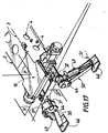
- la figure 21 est une vue en perspective faussée de la partie avant de la machine représentée en figures 19 et 20, le bras étant en position extrême abaissée et non télescopée, le vérin de commande reliant le châssis et le faux châssis n'étant pas figuré pour des raisons de lisibilité.
- elle désigne ici un ensemble de pièces mécaniques reliées directement au pont avant, pont avant qui est, dans l'art antérieur, conventionnellement rattaché au châssis par les éléments de suspension avant, d'où l'emploi du terme 〈〈châssis 〉〉;
- cet ensemble de pièces n'a pas pour fonction de supporter le moteur, la transmission et la carrosserie, à la manière d'un châssis, d'où au total, l'expression 〈〈faux châssis〉〉;
- cet ensemble de pièces peut être adapté sur un châssis traditionnel.
- deux parties latérales 24, optionnelles, d'articulation de stabilisateurs;
- un premier flasque 25 d'articulation des biellettes 17, 18, ce premier flasque 25 étant pourvu à cette fin de trous d'axe 26;
- un deuxième flasque 27 d'articulation de biellettes 17, 18, ce deuxième flasque
27 étant pourvu à cette fin de trous d'axe 28;
les axes 29, 30 définis par les trous d'axes 26, 28 étant parallèles et écartés d'une largeur l'inférieure à celle correspondant à l'écartement l des axes 8, 9 d'articulation supérieure des biellettes 17, 18.
- une plaque rigide 46 apte à être plaquée au sol, montée en rotation à l'extrémité 47 d'un piston 48 d'un ensemble piston-cylindre 49 tel qu'un vérin à double effet, hydraulique ou pneumatique;
- une pièce rigide ou bras 50 de section en U dont l'ouverture est en regard de l'ensemble piston-cylindre 49, le bras 50 étant mobile en rotation autour de l'axe 51 par rapport à la plaque 46.
Claims (15)
- Dispositif apte au contrôle du déplacement relatif de la structure portante d'un engin roulant par rapport à un essieu dudit engin, comprenant un cadre rigide solidaire dudit essieu, ce cadre rigide étant articulé à la structure portante de l'engin, des moyens de commande permettant la rotation du plan horizontal moyen de la structure portante de l'engin par rapport au plan horizontal moyen du cadre rigide solidaire dudit essieu, ledit essieu n'étant pas directement rattaché à la structure portante de l'engin, caractérisé en ce que le cadre rigide comprend:deux biellettes (17, 18) articulées, à une première partie extrême haute, en rotation autour d'axes (8, 9) sensiblement parallèles, par rapport à la structure portante ou châssis (1) de l'engin;deux poutres (31, 32) sensiblement parallèles par rapport auxquelles les biellettes (17, 18) sont articulées en rotation, autour d'axes (29, 30) aux secondes parties extrêmes, basses, de ces biellettes (17, 18);des moyens d'association desdites poutres (31, 32) audit essieu.
- Dispositif selon la revendication 1, caractérisé en ce que chaque biellette (17, 18) est pourvue d'un corps (19) à deux axes de rotation (20, 21) parallèles, chaque axe supérieur de rotation (20) correspondant à un axe (8, 9) et chaque axe inférieur de rotation (21) correspondant à un axe (29, 30).
- Dispositif selon l'une des revendications 1 et 2, caractérisé en ce que l'écartement des axes supérieur (8, 9) de rotation des biellettes est supérieur à l'écartement des axes inférieurs de rotation (29, 30) de ces biellettes (17, 18), ces biellettes (17, 18) étant inclinées d'un angle a ouvert vers le haut par rapport au plan médian P de la structure portante de l'engin, lorsque les deux plans définis par les axes supérieurs (8, 9) et inférieurs (29, 30) sont parallèles.
- Dispositif selon l'une des revendications 1 à 3, caractérisé en ce que l'angle α est compris entre quelques degrés et 30 degrés environ.
- Dispositif selon l'une quelconque des revendications 1 à 4, caractérisé en ce que les moyens de commande du déplacement du cadre rigide par rapport à la structure portante de l'engin comprennent un vérin unique (40) articulé en rotation autour d'un axe (13) sensiblement parallèle aux axes (8, 9) d'articulation haute des biellettes (17, 18), le vérin unique étant articulé en rotation autour d'un axe (39) inférieur sensiblement parallèle aux axes (29, 30) d'articulation basse des biellettes (17, 18).
- Dispositif selon la revendication 5, caractérisé en ce que le vérin (40) est incliné d'un angle β compris entre quelques degrés et 60 degrés par rapport au plan moyen de la structure portante, lorsque les deux plans définis par les axes (8, 9) d'articulation haute et (29, 30) d'articulation basse des biellettes sont parallèles.
- Dispositif selon l'une quelconque des revendications 1 à 6, caractérisé en ce qu'il est rapporté par assemblage sur une structure portante ou châssis conventionnel.
- Dispositif selon l'une quelconque des revendications 1 à 7, caractérisé en ce qu'il est disposé sur la partie extrême avant de la structure portante d'un engin roulant.
- Engin roulant, caractérisé en ce qu'il comprend au moins un dispositif tel que défini dans l'une quelconque des revendications 1 à 8.
- Engin roulant selon la revendication 9, caractérisé en ce qu'il comprend un pont avant et un pont arrière à roues motrices et directrices.
- Engin roulant selon la revendication 9 ou 10, caractérisé en ce qu'il comprend un bras de levage mobile en rotation autour d'un axe sensiblement horizontal (5).
- Engin roulant selon la revendication 11, caractérisé en ce qu'il comprend des moyens d'entraínement disposès latéralement, le poste de pilotage étant placé à l'opposé des moyens d'entraínement.
- Engin roulant selon l'une quelconque des revendications 9 à 12, caractérisé en ce qu'il comprend au moins deux stabilisateurs (45) solidaires du cadre rigide.
- Engin roulant selon l'une quelconque des revendications 9 à 13, caractérisé en ce qu'il comprend une structure porteuse en forme de poutre caisson, à la partie extrême avant de laquelle est placé le dispositif de contrôle de déplacement du cadre formant faux châssis par rapport à la poutre caisson.
- Engin roulant selon la revendication 14, caractérisé en ce qu'il comporte un bras de levage télescopique, le dispositif de contrôle du déplacement du cadre formant faux châssis par rapport à la structure porteuse permettant en combinaison la correction de dévers et le déport latéral de la charge par le biais d'un seul mécanisme.
Applications Claiming Priority (2)
| Application Number | Priority Date | Filing Date | Title |
|---|---|---|---|
| FR9900869A FR2788759B1 (fr) | 1999-01-27 | 1999-01-27 | Dispositif de controle de deplacement d'une structure portante d'engin roulant et engin roulant incorporant ledit dispositif |
| FR9900869 | 1999-01-27 |
Publications (2)
| Publication Number | Publication Date |
|---|---|
| EP1024108A1 true EP1024108A1 (fr) | 2000-08-02 |
| EP1024108B1 EP1024108B1 (fr) | 2003-09-24 |
Family
ID=9541253
Family Applications (1)
| Application Number | Title | Priority Date | Filing Date |
|---|---|---|---|
| EP20000400096 Expired - Lifetime EP1024108B1 (fr) | 1999-01-27 | 2000-01-14 | Dispositif de contrôle de déplacement d'une structure portante d'engin roulant |
Country Status (3)
| Country | Link |
|---|---|
| EP (1) | EP1024108B1 (fr) |
| DE (1) | DE60005415T2 (fr) |
| FR (1) | FR2788759B1 (fr) |
Citations (41)
| Publication number | Priority date | Publication date | Assignee | Title |
|---|---|---|---|---|
| US3178046A (en) | 1962-04-04 | 1965-04-13 | Le Grand H Lull | Mobile loader with extendible boom |
| US3184086A (en) | 1963-05-15 | 1965-05-18 | Le Grand H Lull | High lift mobile loader |
| US3198359A (en) | 1963-01-29 | 1965-08-03 | Le Grand H Lull | Reaching type loader |
| US3270899A (en) | 1964-04-17 | 1966-09-06 | Baldwin Lima Hamilton Corp | Load handling vehicle |
| FR2091898A1 (fr) | 1970-04-09 | 1971-01-21 | Potain Sa | |
| US3670910A (en) | 1970-07-23 | 1972-06-20 | Donald George Shaw | Mobile load handling or lifting machines |
| US3688929A (en) | 1970-09-30 | 1972-09-05 | Skagit Corp | Lift truck with rotatable carriage |
| US3836025A (en) | 1973-05-21 | 1974-09-17 | Loed Corp | Material-handling machine |
| US3937339A (en) | 1971-10-29 | 1976-02-10 | Koehring Company | Vehicle having transverse leveling means |
| FR2287413A1 (fr) | 1974-10-12 | 1976-05-07 | Liner Concrete Machinery | Perfectionnements a des vehicules de manutention de charges |
| FR2287411A1 (fr) | 1974-10-12 | 1976-05-07 | Liner Concrete Machinery | Vehicule de manutention de charges |
| US3967744A (en) | 1975-02-18 | 1976-07-06 | Clark Equipment Company | Extensible reach load lifting mechanism |
| US3985248A (en) | 1974-09-25 | 1976-10-12 | Badger Dynamics, Inc. | Telescopic boom assembly |
| DE2739537A1 (de) | 1976-09-03 | 1978-03-09 | Loed Corp | Schwenkgabelanordnung fuer verladeausruestungen |
| DE2739325A1 (de) | 1976-09-03 | 1978-03-09 | Loed Corp | Verladefahrzeug |
| US4082197A (en) * | 1976-10-12 | 1978-04-04 | Caterpillar Tractor Co. | Articulated high lift vehicle |
| US4147263A (en) | 1977-01-06 | 1979-04-03 | Lull Engineering Company, Inc. | High lift loader with extended transfer |
| EP0036455A1 (fr) | 1980-03-18 | 1981-09-30 | Liner Limited | Véhicule pour le maniement de charges |
| FR2527992A3 (fr) | 1982-06-03 | 1983-12-09 | Merlo Ind Metalmecc | Vehicule a roues dont le chassis est mobile par rapport a l'un des essieux |
| FR2545468A1 (fr) | 1983-05-03 | 1984-11-09 | Koehring Co | Dispositif de montage de fourche sur un chariot elevateur a fourche et procede de dechargement employant un chariot elevateur a fourche comportant un tel dispositif |
| FR2563204A1 (fr) | 1984-04-23 | 1985-10-25 | Koehring Co | Accessoire pour chariot a fourche, et procede de dechargement utilisant cet accessoire |
| US4553899A (en) | 1983-11-16 | 1985-11-19 | Riccardo Magni | High lift truck with telescoping boom assemblies |
| US4632630A (en) | 1983-05-03 | 1986-12-30 | Koehring Company | Forklift attachment |
| US4674944A (en) | 1985-12-27 | 1987-06-23 | Kidde, Inc. | Forklift variable reach mechanism |
| US4679803A (en) | 1986-01-27 | 1987-07-14 | The United States Of America As Represented By The Secretary Of Agriculture | Apparatus for maintaining stability of mobile land vehicles on sloping terrain |
| US4744718A (en) | 1984-03-06 | 1988-05-17 | Gleason Cranes (Vic.) Pty. Ltd. | Aircraft service vehicle |
| WO1989000972A1 (fr) | 1987-07-27 | 1989-02-09 | Merlo S.P.A. Industria Metalmeccanica | Chariot elevateur a bras elevateur telescopique |
| US4822237A (en) | 1985-11-21 | 1989-04-18 | The Gradall Company | Extended reach materials handling apparatus |
| EP0312390A1 (fr) | 1987-10-15 | 1989-04-19 | J.C. Bamford Excavators Limited | Véhicule |
| EP0325064A1 (fr) | 1987-12-18 | 1989-07-26 | Manitou Bf | Amélioration à la stabilité des chariots élévateurs à bras télescopique |
| FR2640206A1 (fr) * | 1988-12-09 | 1990-06-15 | Bringuier Jean Marc | Vehicule du genre " tous terrains " pour prises de vues |
| US4964778A (en) | 1989-07-27 | 1990-10-23 | Kidde Industries, Inc. | Forklift truck having a telescopic auxiliary boom articulated to a telescopic main boom |
| EP0415608A2 (fr) | 1989-08-17 | 1991-03-06 | Eagle-Picher Industries, Inc. | Chariot élévateur à fourche avec un bras télescopique |
| US5106257A (en) | 1990-01-24 | 1992-04-21 | Manitou Bf | Lift truck with telescopic arm |
| EP0577388A2 (fr) | 1992-06-30 | 1994-01-05 | Caterpillar Inc. | Engin de chantier polyvalent |
| EP0656315A1 (fr) | 1993-12-01 | 1995-06-07 | Manitou Bf | Chariot élévateur à bras télescopique |
| EP0680923A1 (fr) | 1994-05-04 | 1995-11-08 | Caterpillar Inc. | Machine de travail |
| EP0681068A1 (fr) | 1994-05-04 | 1995-11-08 | Caterpillar Inc. | Véhicule de travail |
| US5478192A (en) | 1990-02-13 | 1995-12-26 | Tovel Manufacturing Limited | Boom operated fork truck |
| EP0692448A1 (fr) | 1994-07-15 | 1996-01-17 | J.C. Bamford Excavators Limited | Véhicule de manutention de matériel |
| EP0927698A1 (fr) | 1997-11-04 | 1999-07-07 | Karl Schaeff GmbH & Co. Maschinenfabrik | Appareil de travail sur roues mobile transversalement |
-
1999
- 1999-01-27 FR FR9900869A patent/FR2788759B1/fr not_active Expired - Lifetime
-
2000
- 2000-01-14 EP EP20000400096 patent/EP1024108B1/fr not_active Expired - Lifetime
- 2000-01-14 DE DE2000605415 patent/DE60005415T2/de not_active Expired - Lifetime
Patent Citations (45)
| Publication number | Priority date | Publication date | Assignee | Title |
|---|---|---|---|---|
| US3178046A (en) | 1962-04-04 | 1965-04-13 | Le Grand H Lull | Mobile loader with extendible boom |
| US3198359A (en) | 1963-01-29 | 1965-08-03 | Le Grand H Lull | Reaching type loader |
| US3184086A (en) | 1963-05-15 | 1965-05-18 | Le Grand H Lull | High lift mobile loader |
| US3270899A (en) | 1964-04-17 | 1966-09-06 | Baldwin Lima Hamilton Corp | Load handling vehicle |
| FR2091898A1 (fr) | 1970-04-09 | 1971-01-21 | Potain Sa | |
| US3670910A (en) | 1970-07-23 | 1972-06-20 | Donald George Shaw | Mobile load handling or lifting machines |
| US3688929A (en) | 1970-09-30 | 1972-09-05 | Skagit Corp | Lift truck with rotatable carriage |
| US3937339A (en) | 1971-10-29 | 1976-02-10 | Koehring Company | Vehicle having transverse leveling means |
| US3836025A (en) | 1973-05-21 | 1974-09-17 | Loed Corp | Material-handling machine |
| US3985248A (en) | 1974-09-25 | 1976-10-12 | Badger Dynamics, Inc. | Telescopic boom assembly |
| FR2287411A1 (fr) | 1974-10-12 | 1976-05-07 | Liner Concrete Machinery | Vehicule de manutention de charges |
| FR2287413A1 (fr) | 1974-10-12 | 1976-05-07 | Liner Concrete Machinery | Perfectionnements a des vehicules de manutention de charges |
| US4034875A (en) | 1974-10-12 | 1977-07-12 | The Liner Concrete Machinery Company Limited | Load handling vehicle |
| US3967744A (en) | 1975-02-18 | 1976-07-06 | Clark Equipment Company | Extensible reach load lifting mechanism |
| DE2739537A1 (de) | 1976-09-03 | 1978-03-09 | Loed Corp | Schwenkgabelanordnung fuer verladeausruestungen |
| DE2739325A1 (de) | 1976-09-03 | 1978-03-09 | Loed Corp | Verladefahrzeug |
| US4082197A (en) * | 1976-10-12 | 1978-04-04 | Caterpillar Tractor Co. | Articulated high lift vehicle |
| US4147263A (en) | 1977-01-06 | 1979-04-03 | Lull Engineering Company, Inc. | High lift loader with extended transfer |
| EP0036455A1 (fr) | 1980-03-18 | 1981-09-30 | Liner Limited | Véhicule pour le maniement de charges |
| FR2527992A3 (fr) | 1982-06-03 | 1983-12-09 | Merlo Ind Metalmecc | Vehicule a roues dont le chassis est mobile par rapport a l'un des essieux |
| FR2545468A1 (fr) | 1983-05-03 | 1984-11-09 | Koehring Co | Dispositif de montage de fourche sur un chariot elevateur a fourche et procede de dechargement employant un chariot elevateur a fourche comportant un tel dispositif |
| US4632630A (en) | 1983-05-03 | 1986-12-30 | Koehring Company | Forklift attachment |
| US4553899A (en) | 1983-11-16 | 1985-11-19 | Riccardo Magni | High lift truck with telescoping boom assemblies |
| US4744718A (en) | 1984-03-06 | 1988-05-17 | Gleason Cranes (Vic.) Pty. Ltd. | Aircraft service vehicle |
| FR2563204A1 (fr) | 1984-04-23 | 1985-10-25 | Koehring Co | Accessoire pour chariot a fourche, et procede de dechargement utilisant cet accessoire |
| US4822237A (en) | 1985-11-21 | 1989-04-18 | The Gradall Company | Extended reach materials handling apparatus |
| US4674944A (en) | 1985-12-27 | 1987-06-23 | Kidde, Inc. | Forklift variable reach mechanism |
| EP0228208A1 (fr) | 1985-12-27 | 1987-07-08 | Kidde, Inc. | Chariot élévateur à mécanisme de portée variable |
| US4679803A (en) | 1986-01-27 | 1987-07-14 | The United States Of America As Represented By The Secretary Of Agriculture | Apparatus for maintaining stability of mobile land vehicles on sloping terrain |
| US5199861A (en) | 1987-07-27 | 1993-04-06 | Merlo S.P.A. Industria Metalmeccanica | Lifting truck with a telescopic lifting arm |
| WO1989000972A1 (fr) | 1987-07-27 | 1989-02-09 | Merlo S.P.A. Industria Metalmeccanica | Chariot elevateur a bras elevateur telescopique |
| EP0312390A1 (fr) | 1987-10-15 | 1989-04-19 | J.C. Bamford Excavators Limited | Véhicule |
| EP0325064A1 (fr) | 1987-12-18 | 1989-07-26 | Manitou Bf | Amélioration à la stabilité des chariots élévateurs à bras télescopique |
| FR2640206A1 (fr) * | 1988-12-09 | 1990-06-15 | Bringuier Jean Marc | Vehicule du genre " tous terrains " pour prises de vues |
| US4964778A (en) | 1989-07-27 | 1990-10-23 | Kidde Industries, Inc. | Forklift truck having a telescopic auxiliary boom articulated to a telescopic main boom |
| EP0415608A2 (fr) | 1989-08-17 | 1991-03-06 | Eagle-Picher Industries, Inc. | Chariot élévateur à fourche avec un bras télescopique |
| US5106257A (en) | 1990-01-24 | 1992-04-21 | Manitou Bf | Lift truck with telescopic arm |
| US5478192A (en) | 1990-02-13 | 1995-12-26 | Tovel Manufacturing Limited | Boom operated fork truck |
| EP0577388A2 (fr) | 1992-06-30 | 1994-01-05 | Caterpillar Inc. | Engin de chantier polyvalent |
| EP0656315A1 (fr) | 1993-12-01 | 1995-06-07 | Manitou Bf | Chariot élévateur à bras télescopique |
| FR2713155A1 (fr) | 1993-12-01 | 1995-06-09 | Manitou Bf | Chariot élévateur à bras télescopique. |
| EP0680923A1 (fr) | 1994-05-04 | 1995-11-08 | Caterpillar Inc. | Machine de travail |
| EP0681068A1 (fr) | 1994-05-04 | 1995-11-08 | Caterpillar Inc. | Véhicule de travail |
| EP0692448A1 (fr) | 1994-07-15 | 1996-01-17 | J.C. Bamford Excavators Limited | Véhicule de manutention de matériel |
| EP0927698A1 (fr) | 1997-11-04 | 1999-07-07 | Karl Schaeff GmbH & Co. Maschinenfabrik | Appareil de travail sur roues mobile transversalement |
Also Published As
| Publication number | Publication date |
|---|---|
| DE60005415D1 (de) | 2003-10-30 |
| DE60005415T2 (de) | 2004-06-17 |
| FR2788759A1 (fr) | 2000-07-28 |
| FR2788759B1 (fr) | 2001-03-23 |
| EP1024108B1 (fr) | 2003-09-24 |
Similar Documents
| Publication | Publication Date | Title |
|---|---|---|
| EP0046234B1 (fr) | Véhicule de manutention et de terrassement | |
| EP1965630B1 (fr) | Engin agricole comportant un attelage perfectionne | |
| FR2528409A1 (fr) | Equipement complementaire sur grue automotrice a fleche telescopique | |
| EP0100926B1 (fr) | Véhicule de manutention à bras orientable et châssis stabilisateur incorporé | |
| EP1061034B1 (fr) | Chariot automoteur à bras télescopique et rehausse | |
| EP1024108B1 (fr) | Dispositif de contrôle de déplacement d'une structure portante d'engin roulant | |
| FR2747665A1 (fr) | Chariot elevateur a cadre relevable | |
| WO1979001075A1 (fr) | Engin polyvalent de terrassement et de manutention | |
| EP0873964B1 (fr) | Dispositif de relevage de mât pour grue à tour télescopique | |
| FR2759662A1 (fr) | Chassis de chariot elevateur, chariot elevateur comportant un tel chassis et procede de fabrication d'un tel chariot | |
| FR2536735A1 (fr) | Chariot de travail notamment pour la pose des vitres de toitures des serres agricoles | |
| EP0024265B2 (fr) | Véhicule à deux plates-formes superposées pour le transport de véhicules automobiles, avec plate-forme supérieure inclinable et abaissable | |
| FR2559441A1 (fr) | Engin mobile comportant un dispositif de stabilisation | |
| EP0919509A1 (fr) | Dispositif de manutention de conteneurs | |
| FR2485451A1 (fr) | Vehicule tracteur enjambeur a palonniers sustentateurs pour applications diverses | |
| EP1077196B1 (fr) | Dispositif de correction de dévers pour véhicule à deux essieux | |
| FR2534110A1 (fr) | Dispositif destine a supporter, au moins partiellement, le poids d'une machine agricole | |
| FR2461436A1 (fr) | Dispositif amovible de transport et de manoeuvre d'outil pouvant etre monte sur un tacteur | |
| EP2910513A1 (fr) | Engin de levage avec réglage de garde au sol | |
| EP0629160B1 (fr) | Dispositif pour vehicule de transport routier ou de manoeuvre et vehicule equipe d'un tel dispositif | |
| EP1442969B1 (fr) | Véhicule à chenilles à train de roulement de longeur variable | |
| FR2774670A1 (fr) | Engin roulant mobile a portee variable et fleche orientable telescopique | |
| FR2909366A1 (fr) | Engin de levage | |
| FR2849009A1 (fr) | Chariot semi-industriel, a portee variable, pour la manutention de materiaux | |
| WO2026008599A1 (fr) | Grue de chantier portable et mobile sous charge |
Legal Events
| Date | Code | Title | Description |
|---|---|---|---|
| PUAI | Public reference made under article 153(3) epc to a published international application that has entered the european phase |
Free format text: ORIGINAL CODE: 0009012 |
|
| AK | Designated contracting states |
Kind code of ref document: A1 Designated state(s): DE FR GB IT |
|
| AX | Request for extension of the european patent |
Free format text: AL;LT;LV;MK;RO;SI |
|
| 17P | Request for examination filed |
Effective date: 20000919 |
|
| AKX | Designation fees paid |
Free format text: DE FR GB IT |
|
| 17Q | First examination report despatched |
Effective date: 20020802 |
|
| GRAH | Despatch of communication of intention to grant a patent |
Free format text: ORIGINAL CODE: EPIDOS IGRA |
|
| GRAH | Despatch of communication of intention to grant a patent |
Free format text: ORIGINAL CODE: EPIDOS IGRA |
|
| GRAA | (expected) grant |
Free format text: ORIGINAL CODE: 0009210 |
|
| RAP1 | Party data changed (applicant data changed or rights of an application transferred) |
Owner name: BOBCAT FRANCE SA |
|
| AK | Designated contracting states |
Kind code of ref document: B1 Designated state(s): DE FR GB IT |
|
| REG | Reference to a national code |
Ref country code: GB Ref legal event code: FG4D Free format text: NOT ENGLISH |
|
| GBT | Gb: translation of ep patent filed (gb section 77(6)(a)/1977) | ||
| REF | Corresponds to: |
Ref document number: 60005415 Country of ref document: DE Date of ref document: 20031030 Kind code of ref document: P |
|
| PLBE | No opposition filed within time limit |
Free format text: ORIGINAL CODE: 0009261 |
|
| STAA | Information on the status of an ep patent application or granted ep patent |
Free format text: STATUS: NO OPPOSITION FILED WITHIN TIME LIMIT |
|
| 26N | No opposition filed |
Effective date: 20040625 |
|
| REG | Reference to a national code |
Ref country code: FR Ref legal event code: PLFP Year of fee payment: 17 |
|
| REG | Reference to a national code |
Ref country code: FR Ref legal event code: PLFP Year of fee payment: 18 |
|
| REG | Reference to a national code |
Ref country code: FR Ref legal event code: PLFP Year of fee payment: 19 |
|
| PGFP | Annual fee paid to national office [announced via postgrant information from national office to epo] |
Ref country code: IT Payment date: 20190121 Year of fee payment: 20 Ref country code: FR Payment date: 20190130 Year of fee payment: 20 Ref country code: GB Payment date: 20190130 Year of fee payment: 20 Ref country code: DE Payment date: 20190130 Year of fee payment: 20 |
|
| REG | Reference to a national code |
Ref country code: DE Ref legal event code: R071 Ref document number: 60005415 Country of ref document: DE |
|
| REG | Reference to a national code |
Ref country code: GB Ref legal event code: PE20 Expiry date: 20200113 |
|
| PG25 | Lapsed in a contracting state [announced via postgrant information from national office to epo] |
Ref country code: GB Free format text: LAPSE BECAUSE OF EXPIRATION OF PROTECTION Effective date: 20200113 |