EP1024104A1 - Nebenvorrichtung zur Notflucht für Aufzug - Google Patents
Nebenvorrichtung zur Notflucht für Aufzug Download PDFInfo
- Publication number
- EP1024104A1 EP1024104A1 EP99101484A EP99101484A EP1024104A1 EP 1024104 A1 EP1024104 A1 EP 1024104A1 EP 99101484 A EP99101484 A EP 99101484A EP 99101484 A EP99101484 A EP 99101484A EP 1024104 A1 EP1024104 A1 EP 1024104A1
- Authority
- EP
- European Patent Office
- Prior art keywords
- compression
- elevator
- elevator cab
- fastened
- decompression
- Prior art date
- Legal status (The legal status is an assumption and is not a legal conclusion. Google has not performed a legal analysis and makes no representation as to the accuracy of the status listed.)
- Withdrawn
Links
- 230000006835 compression Effects 0.000 claims abstract description 33
- 238000007906 compression Methods 0.000 claims abstract description 33
- 230000006837 decompression Effects 0.000 claims abstract description 25
- 239000012530 fluid Substances 0.000 claims abstract description 9
- 230000003213 activating effect Effects 0.000 claims 1
- 238000012423 maintenance Methods 0.000 description 2
- 230000015556 catabolic process Effects 0.000 description 1
- 238000010276 construction Methods 0.000 description 1
Images


Classifications
-
- B—PERFORMING OPERATIONS; TRANSPORTING
- B66—HOISTING; LIFTING; HAULING
- B66B—ELEVATORS; ESCALATORS OR MOVING WALKWAYS
- B66B5/00—Applications of checking, fault-correcting, or safety devices in elevators
- B66B5/02—Applications of checking, fault-correcting, or safety devices in elevators responsive to abnormal operating conditions
- B66B5/027—Applications of checking, fault-correcting, or safety devices in elevators responsive to abnormal operating conditions to permit passengers to leave an elevator car in case of failure, e.g. moving the car to a reference floor or unlocking the door
-
- B—PERFORMING OPERATIONS; TRANSPORTING
- B66—HOISTING; LIFTING; HAULING
- B66B—ELEVATORS; ESCALATORS OR MOVING WALKWAYS
- B66B5/00—Applications of checking, fault-correcting, or safety devices in elevators
- B66B5/02—Applications of checking, fault-correcting, or safety devices in elevators responsive to abnormal operating conditions
- B66B5/028—Safety devices separate from control system in case of power failure, for hydraulical lifts, e.g. braking the hydraulic jack
Definitions
- the present invention relates generally to an elevator, and more particularly to an auxiliary emergency escape device of the elevator.
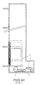
- a prior art elevator comprises an oil pressure mechanism 1 for actuating an oil pressure cylinder 2 to move up and down.
- the oil pressure cylinder 2 is fastened at one end thereof with an elevator cab 3.
- the oil pressure mechanism 1 is provided with a decompression valve 4, which is intended for use by an elevator maintenance personnel to lower the elevator cab 3 in the event of a power outage, an elevator breakdown, or an elevator maintenance work.
- the elevator cab 3 may be caused by a power outage or accident to stop somewhere between two floors such that the door of the elevator cab 3 can not be opened, and that the passengers are trapped in the disabled cab.
- the primary objective of the present invention is therefore to provide an elevator with an auxiliary emergency escape device, which comprises a manually-operated compression-decompression device located at the emergency window of the elevator cab.
- the compression-decompression device is fastened at one end thereof with an oil pipe which is in turn fastened at another end thereof with a compression valve.
- the compression valve is fastened at one end thereof with an oil pressure mechanism.
- the compression-decompression device is exerted on by the pressure of a person's hand so as to actuate the compression valve or the decompression valve, thereby causing the oil pressure cylinder to move up or down.
- the elevator cab can be manually driven to a desired floor where the trapped passengers can escape.
- FIG. 1 shows a schematic view of the operating mechanism of a prior art elevator.
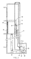
- FIG. 2 shows a schematic view of the operating mechanism of an elevator of the present invention.
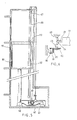
- FIG. 3 shows an enlarged schematic view of a manually-operated compression device of the present invention.
- FIG. 4 shows a schematic view of a compression valve of the present invention.
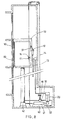
- FIG. 5 shows a schematic view of a manually-operated compression device of another embodiment of the present invention.
- FIG. 6 shows a partial schematic plan view of the compression device as shown in FIG. 5.
- FIG. 7 shows a schematic view of an emergency window of the embodiment as shown in FIG. 5.
- FIG. 8 shows a schematic view of the construction of still another embodiment of the present invention.
- FIG. 9 shows a partial enlarged schematic view of the embodiment as shown in FIG. 8.
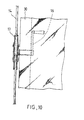
- FIG. 10 shows a side view of the embodiment as shown in FIG. 8.
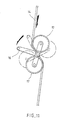
- FIG. 11 shows a schematic view of the operation of the embodiment as shown in FIG. 10.
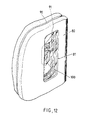
- FIG. 12 shows a perspective view of a cab door of the elevator of the present invention.
- an elevator auxiliary emergency escape device embodied in the present invention is composed of a manually-operated compression apparatus 10 and a compression valve 20.
- the manually-operated compression apparatus 10 is made up of a handle 11 and a piston 12.
- the compression apparatus 10 is fastened at one end thereof with an oil pipe 13 and is located at an emergency window 31 of an elevator cab 30 of the present invention.
- the compression valve 20 is composed of a piston 21 and a push rod 22.
- the compression valve 20 is fastened at one end thereof with the oil pipe 13.
- the compression valve 20 is connected with an oil pressure mechanism 41 by a lever apparatus 50.
- the oil pressure mechanism 41 is located over an oil tank 40.
- the push rod 22 of the compression valve 20 is engaged with an arcuate hole 51 of the longer end of the lever apparatus 50.
- the oil pressure mechanism 41 is engaged with the short end of the lever apparatus 50 by means of a linking rod 52.
- the lever apparatus 50 is intended to provide a leverage to facilitate the efficient action of the compression valve 20 on the oil pressure mechanism 41.
- the length of the oil pipe 13 depends on the height of a building in which the elevator is located.
- the midpoint of the oil pipe 13 is corresponding in location to the midpoint of the building.
- a trapped passenger can reach for the handle 11 of the manually-operated compression device 10 from the emergency window 31 of the elevator cab 30.
- the piston 12 can be actuated by an external pressure exerting on the handle 11 by the hand of the trapped passenger such that the fluid contained in the oil pipe 13 is compressed by the piston 12 to act on the compression valve 20.
- the piston 21 of the compression valve 20 is at work such that the push rod 22 is actuated to cause the linking rod 52 of the lever apparatus 50 to act on the oil pressure mechanism 41, which in turn gives an added pressure to the oil pressure cylinder 42.
- the elevator cab 30 is thus lifted by the oil pressure cylinder 42.
- a manually-operated compression device 60 of another embodiment of the present invention is located over the oil tank 40.
- a pulley set 61 is mounted over the oil tank 40 and is provided with a driving sector gear 611 and a driven sector gear 62 which is engaged with the driving sector gear 611 and is provided at one end thereof with two bearings 63 opposite to each other.
- One of the bearings 63 is fastened pivotally with the driven sector gear 62.
- the bearings 63 are provided therebetween with an eccentric shaft 64 with a push rod 65 being fastened pivotally therewith.
- the push rod 65 is fastened with the oil pressure mechanism 41.
- An action cable 66 is fastened at one end thereof with a revolving wheel 66 which is located at the top end of the elevator shaft.
- the action cable 66 is wound on the pulley set 61.
- the elevator cab 30 is provided with an emergency window 32 and a mask 33 fitted over the action cable 66.
- a decompression valve 70 can be actuated by an external force exerting on an action cable 14 by a passenger trapped in the disabled cab 30.
- the decompression valve 70 is activated by the pressure of a hand of the trapped passenger, the fluid contained in the oil pressure cylinder 42 is so drained that the fluid flows back into the fluid storage tank.
- the elevator cab 30 is caused to descend gradually.
- the trapped passenger can observe through the see-through window 81 of the inner door 80 of the elevator cab 30, as illustrated in FIG. 12.
- the action cable 14 is released to interrupt the draining of the fluid of the oil pressure cylinder 42. In other words, as soon as the action cable 14 is let go by the trapped passenger, the elevator cab 30 in motion is stopped at once.
- one end of the action cable 14 in located securely at the bottom of the elevator shaft.
- the elevator cab 30 is provided therein with an action rod 16 which is engaged through the wall of the cab 30 with two balance wheels 17.
- the action cable 14 is put through between the two balance wheels 17.
- the balance wheels 17 can be actuated by the action rod 16 to engage in a planetary motion such that the action cable 14 is curved and that the decompression valve 70 is actuated to bring about the draining of the fluid of the oil pressure cylinder 42, thereby causing the elevator cab 30 to descend slowly.
- Located at the junction of the action cable 14 and the decompression valve 70 is a coil spring 18 for balancing the torsion of the action cable 14 and the balance wheels 17.
- the decompression valve 70 can not be accidentally activated as long as the action cable 14 is not exerted on by the force of the action rod 16 which is located inside the elevator cab 30 to safeguard the operator.
- the embodiments of the present invention described above are to be deemed in all respects as being merely illustrative and not restrictive. Accordingly, the present invention may be embodied in other specific forms without deviating from the spirit thereof. The present invention is therefore to be limited only by the scopes of the following appended claims.
Landscapes
- Engineering & Computer Science (AREA)
- Automation & Control Theory (AREA)
- Maintenance And Inspection Apparatuses For Elevators (AREA)
Priority Applications (1)
| Application Number | Priority Date | Filing Date | Title |
|---|---|---|---|
| EP99101484A EP1024104A1 (de) | 1999-01-27 | 1999-01-27 | Nebenvorrichtung zur Notflucht für Aufzug |
Applications Claiming Priority (1)
| Application Number | Priority Date | Filing Date | Title |
|---|---|---|---|
| EP99101484A EP1024104A1 (de) | 1999-01-27 | 1999-01-27 | Nebenvorrichtung zur Notflucht für Aufzug |
Publications (1)
| Publication Number | Publication Date |
|---|---|
| EP1024104A1 true EP1024104A1 (de) | 2000-08-02 |
Family
ID=8237427
Family Applications (1)
| Application Number | Title | Priority Date | Filing Date |
|---|---|---|---|
| EP99101484A Withdrawn EP1024104A1 (de) | 1999-01-27 | 1999-01-27 | Nebenvorrichtung zur Notflucht für Aufzug |
Country Status (1)
| Country | Link |
|---|---|
| EP (1) | EP1024104A1 (de) |
Citations (5)
| Publication number | Priority date | Publication date | Assignee | Title |
|---|---|---|---|---|
| US4434875A (en) * | 1981-05-12 | 1984-03-06 | Sergio Scarzella | Emergency levelling device for a lift car |
| WO1987005282A1 (en) * | 1986-03-03 | 1987-09-11 | Oly Fischer Dos Santos | Emergency device for elevators |
| US5370206A (en) * | 1993-09-24 | 1994-12-06 | Chao; Wen-Ping | Driving system for elevator |
| EP0820954A1 (de) * | 1996-07-25 | 1998-01-28 | Chiu Nan Wang | Notfluchtvorrichtung für Aufzug |
| DE19646453A1 (de) * | 1996-10-29 | 1998-05-14 | Chiu Nan Wang | Hydraulische Fluchthilfsvorrichtung für Aufzüge |
-
1999
- 1999-01-27 EP EP99101484A patent/EP1024104A1/de not_active Withdrawn
Patent Citations (5)
| Publication number | Priority date | Publication date | Assignee | Title |
|---|---|---|---|---|
| US4434875A (en) * | 1981-05-12 | 1984-03-06 | Sergio Scarzella | Emergency levelling device for a lift car |
| WO1987005282A1 (en) * | 1986-03-03 | 1987-09-11 | Oly Fischer Dos Santos | Emergency device for elevators |
| US5370206A (en) * | 1993-09-24 | 1994-12-06 | Chao; Wen-Ping | Driving system for elevator |
| EP0820954A1 (de) * | 1996-07-25 | 1998-01-28 | Chiu Nan Wang | Notfluchtvorrichtung für Aufzug |
| DE19646453A1 (de) * | 1996-10-29 | 1998-05-14 | Chiu Nan Wang | Hydraulische Fluchthilfsvorrichtung für Aufzüge |
Similar Documents
| Publication | Publication Date | Title |
|---|---|---|
| US5906252A (en) | Oil pressure auxiliary escape device of elevator | |
| AU5015599A (en) | Emergency release device | |
| US4493396A (en) | Winch for safely lowering a person at a controlled rate | |
| US5878845A (en) | Auxiliary emergency escape device of elevator | |
| JP4672017B2 (ja) | 救命装備 | |
| CN105819310A (zh) | 一种具有手动自救缓降功能的双曳引驱动电梯 | |
| CN110759271B (zh) | 一种起重机断电下降吊物装置 | |
| JP2754365B2 (ja) | エレベータの緊急避難装置 | |
| US20020125076A1 (en) | Elevator emergency escape device | |
| CN1972856B (zh) | 一种用于升降被困电梯的应急装置 | |
| US20150123056A1 (en) | Tackle for displacing a load | |
| EP1024104A1 (de) | Nebenvorrichtung zur Notflucht für Aufzug | |
| CN112299200B (zh) | 一种液压电梯安全防护装置及其安全防护方法 | |
| US6557670B2 (en) | Double brake protection device for elevator | |
| CN101823658A (zh) | 无机房电梯手动拉线式救援装置 | |
| JP2000229770A (ja) | エレベータの緊急避難補助装置 | |
| CN1063726C (zh) | 电梯安全脱困装置 | |
| CN105347213A (zh) | 一种卷筒 | |
| GB2407554A (en) | Emergency descent of lift cage | |
| CN211871240U (zh) | 阳台升降装置 | |
| KR100763830B1 (ko) | 엘리베이터용 로프제동장치 | |
| JP2886132B2 (ja) | エレベーター装置 | |
| US7607515B2 (en) | Elevator evacuation apparatus | |
| CN2417085Y (zh) | 套缸式快速起升的轮式液压千斤顶 | |
| KR100468877B1 (ko) | 스프라그 잭 권양기 |
Legal Events
| Date | Code | Title | Description |
|---|---|---|---|
| PUAI | Public reference made under article 153(3) epc to a published international application that has entered the european phase |
Free format text: ORIGINAL CODE: 0009012 |
|
| AK | Designated contracting states |
Kind code of ref document: A1 Designated state(s): CH DE FI FR GB IT LI NL |
|
| AX | Request for extension of the european patent |
Free format text: AL;LT;LV;MK;RO;SI |
|
| 17P | Request for examination filed |
Effective date: 20010125 |
|
| AKX | Designation fees paid |
Free format text: CH DE FI FR GB IT LI NL |
|
| STAA | Information on the status of an ep patent application or granted ep patent |
Free format text: STATUS: THE APPLICATION HAS BEEN WITHDRAWN |
|
| 18W | Application withdrawn |
Withdrawal date: 20020927 |