EP1024081A2 - Blattwurzel für Propeller- und Rotorblätter - Google Patents
Blattwurzel für Propeller- und Rotorblätter Download PDFInfo
- Publication number
- EP1024081A2 EP1024081A2 EP00101623A EP00101623A EP1024081A2 EP 1024081 A2 EP1024081 A2 EP 1024081A2 EP 00101623 A EP00101623 A EP 00101623A EP 00101623 A EP00101623 A EP 00101623A EP 1024081 A2 EP1024081 A2 EP 1024081A2
- Authority
- EP
- European Patent Office
- Prior art keywords
- leaf
- sleeve
- blade
- root
- fiber
- Prior art date
- Legal status (The legal status is an assumption and is not a legal conclusion. Google has not performed a legal analysis and makes no representation as to the accuracy of the status listed.)
- Granted
Links
- 229920002430 Fibre-reinforced plastic Polymers 0.000 claims abstract description 16
- 239000011151 fibre-reinforced plastic Substances 0.000 claims abstract description 16
- 230000000694 effects Effects 0.000 claims abstract description 4
- 238000004026 adhesive bonding Methods 0.000 claims description 5
- 239000000463 material Substances 0.000 claims description 4
- 229910000831 Steel Inorganic materials 0.000 claims description 3
- RTAQQCXQSZGOHL-UHFFFAOYSA-N Titanium Chemical compound [Ti] RTAQQCXQSZGOHL-UHFFFAOYSA-N 0.000 claims description 3
- 239000000956 alloy Substances 0.000 claims description 3
- 229910045601 alloy Inorganic materials 0.000 claims description 3
- 229910052782 aluminium Inorganic materials 0.000 claims description 3
- XAGFODPZIPBFFR-UHFFFAOYSA-N aluminium Chemical compound [Al] XAGFODPZIPBFFR-UHFFFAOYSA-N 0.000 claims description 3
- 239000010959 steel Substances 0.000 claims description 3
- 239000010936 titanium Substances 0.000 claims description 3
- 229910052719 titanium Inorganic materials 0.000 claims description 3
- 239000000853 adhesive Substances 0.000 abstract 1
- 230000001070 adhesive effect Effects 0.000 abstract 1
- 238000010276 construction Methods 0.000 description 10
- 238000004519 manufacturing process Methods 0.000 description 5
- 238000003860 storage Methods 0.000 description 4
- 229910052751 metal Inorganic materials 0.000 description 3
- 239000002184 metal Substances 0.000 description 3
- 229920003023 plastic Polymers 0.000 description 3
- 239000004033 plastic Substances 0.000 description 3
- 239000002131 composite material Substances 0.000 description 2
- 230000006378 damage Effects 0.000 description 2
- 239000000835 fiber Substances 0.000 description 2
- 230000007257 malfunction Effects 0.000 description 2
- 230000036316 preload Effects 0.000 description 2
- 239000002023 wood Substances 0.000 description 2
- 238000006243 chemical reaction Methods 0.000 description 1
- 238000005516 engineering process Methods 0.000 description 1
- 239000003292 glue Substances 0.000 description 1
- 238000007689 inspection Methods 0.000 description 1
- 239000000314 lubricant Substances 0.000 description 1
- 239000011159 matrix material Substances 0.000 description 1
- 238000005457 optimization Methods 0.000 description 1
- 230000002028 premature Effects 0.000 description 1
- 230000003313 weakening effect Effects 0.000 description 1
Images
Classifications
-
- F—MECHANICAL ENGINEERING; LIGHTING; HEATING; WEAPONS; BLASTING
- F04—POSITIVE - DISPLACEMENT MACHINES FOR LIQUIDS; PUMPS FOR LIQUIDS OR ELASTIC FLUIDS
- F04D—NON-POSITIVE-DISPLACEMENT PUMPS
- F04D29/00—Details, component parts, or accessories
- F04D29/26—Rotors specially for elastic fluids
- F04D29/32—Rotors specially for elastic fluids for axial flow pumps
- F04D29/38—Blades
- F04D29/388—Blades characterised by construction
-
- B—PERFORMING OPERATIONS; TRANSPORTING
- B64—AIRCRAFT; AVIATION; COSMONAUTICS
- B64C—AEROPLANES; HELICOPTERS
- B64C11/00—Propellers, e.g. of ducted type; Features common to propellers and rotors for rotorcraft
- B64C11/02—Hub construction
- B64C11/04—Blade mountings
- B64C11/06—Blade mountings for variable-pitch blades
-
- B—PERFORMING OPERATIONS; TRANSPORTING
- B64—AIRCRAFT; AVIATION; COSMONAUTICS
- B64C—AEROPLANES; HELICOPTERS
- B64C11/00—Propellers, e.g. of ducted type; Features common to propellers and rotors for rotorcraft
- B64C11/16—Blades
- B64C11/20—Constructional features
- B64C11/26—Fabricated blades
-
- F—MECHANICAL ENGINEERING; LIGHTING; HEATING; WEAPONS; BLASTING
- F03—MACHINES OR ENGINES FOR LIQUIDS; WIND, SPRING, OR WEIGHT MOTORS; PRODUCING MECHANICAL POWER OR A REACTIVE PROPULSIVE THRUST, NOT OTHERWISE PROVIDED FOR
- F03D—WIND MOTORS
- F03D1/00—Wind motors with rotation axis substantially parallel to the air flow entering the rotor
- F03D1/06—Rotors
- F03D1/065—Rotors characterised by their construction elements
- F03D1/0658—Arrangements for fixing wind-engaging parts to a hub
-
- F—MECHANICAL ENGINEERING; LIGHTING; HEATING; WEAPONS; BLASTING
- F04—POSITIVE - DISPLACEMENT MACHINES FOR LIQUIDS; PUMPS FOR LIQUIDS OR ELASTIC FLUIDS
- F04D—NON-POSITIVE-DISPLACEMENT PUMPS
- F04D29/00—Details, component parts, or accessories
- F04D29/26—Rotors specially for elastic fluids
- F04D29/32—Rotors specially for elastic fluids for axial flow pumps
- F04D29/34—Blade mountings
- F04D29/36—Blade mountings adjustable
-
- Y—GENERAL TAGGING OF NEW TECHNOLOGICAL DEVELOPMENTS; GENERAL TAGGING OF CROSS-SECTIONAL TECHNOLOGIES SPANNING OVER SEVERAL SECTIONS OF THE IPC; TECHNICAL SUBJECTS COVERED BY FORMER USPC CROSS-REFERENCE ART COLLECTIONS [XRACs] AND DIGESTS
- Y02—TECHNOLOGIES OR APPLICATIONS FOR MITIGATION OR ADAPTATION AGAINST CLIMATE CHANGE
- Y02E—REDUCTION OF GREENHOUSE GAS [GHG] EMISSIONS, RELATED TO ENERGY GENERATION, TRANSMISSION OR DISTRIBUTION
- Y02E10/00—Energy generation through renewable energy sources
- Y02E10/70—Wind energy
- Y02E10/72—Wind turbines with rotation axis in wind direction
Definitions
- the invention relates to a batt root for propeller and Rotor blades made of fiber-reinforced plastic for arrangement in propeller or rotor hubs of aircraft, ground effect vehicles, Wind power generators or blowers with adjustable or adjustable incline with a divided Leaf sleeve and a base body, the leaf body is arranged between the base body and the leaf sleeve, according to the preamble of claim 1.
- Rotor blades are for optimization their efficiency can be set at standstill or during operation adjustable.
- a leaf root construction for adjustable propeller blades made of fiber-reinforced Plastic of the type mentioned is known, in which the Leaf root also with a split leaf sleeve Attachment is provided on a propeller hub.
- the leaf root is attached to the screw bolt Leaf root attached, with the bolt going through the leaf sleeve base in a base body in the Leaf root extends.
- the disadvantage of this design is that the flange on lower end of the split leaf sleeve between one Flange at the bottom of the body and a ring is clamped, the required clamping force using of the screw bolt that can be screwed into the base body is applied. This weakens the body and there may be local spikes that destruction of the leaf root and loss of leaf to lead. It is also possible that the bolt loosens, which leads to a reduction in the screw preload and thus to an early failure of the Screw connection leads. There is also a local one increased surface pressure between the flange of the split Leaf sleeve and the flange of the body, which are also the durability is reduced.
- EP-PS 0 324 617 shows and describes a leaf body made of fiber-reinforced plastic on its lower part has a cylindrical leaf root, over which a one-piece Leaf sleeve is arranged.
- the durability This construction is achieved in that the end of the cylindrical part of the leaf root with a wedge-shaped Expansion of the diameter is connected by a inner flange bushing is supported. This will make one possible Prevents the leaf body from moving out of the leaf sleeve.
- this construction is manufacturing technology very complex and difficult and therefore expensive.
- the leaf root according to the invention is the leaf sleeve formed as a split molded part, whereby the manufacture of blade roots in propeller or rotor blades made of fiber-reinforced Plastic is simplified because of sheet production until the last operation without a leaf sleeve can and thus damage the surface of the Leaf sleeve avoided, which leads to poor fit the sheet storage or lead to a leak.
- blade sleeve either made of steel, Aluminum, titanium or an alloy of these materials.
- Such a material is light and yet has the required strength.
- the sheet is lying there on the metal of the leaf sleeve and not on the Fiber composite of the leaf body. Is also one mechanical processing of the surface of the blade body on Leaf root section on which the leaf sleeve sits, possible to better fit the blade sleeve too to reach. Since the split leaf sleeve on the finished Leaf root is glued on, can also be a perfect one Form fit can be achieved. The leaf sleeve can continue without great effort removed for inspection purposes to expose the part of the leaf root that is exposed to the greatest loads.
- a further advantageous embodiment of the invention exists in that the leaf sleeve halves are formed without a gap are and connected to each other by means of two clamping rings are.
- the tension rings not only for Assembly of the blade sleeve halves are provided.
- the outer clamping ring is also used for Attachment of flyweights. These flyweights will be in propellers for aerobatic aircraft or multi-engine aircraft needed to adjust the natural propeller blades to reverse in the direction of a small slope.
- an adjustment pin is provided in the area of the flange for transferring the adjustment forces of the adjustment device is arranged on the leaf body, which itself through the base body, the leaf body and the leaf sleeve extends parallel to the longitudinal axis of the leaf root.
- This adjustment pin also serves as a backup to one To prevent twisting of the leaf body relative to the leaf sleeve. It is advantageous that the attachment of the Hole for the adjusting pin only when the final assembly of the Propellers can be made, and thus the position of the adjusting pin Depending on the application, it can be freely selected, which means that the storage of leaves can be reduced because of that Position of the adjustment pin not during the manufacturing process must be determined.
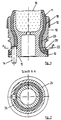
- the leaf root shown in Figs. 1 and 2 consists from a divided, from two leaf sleeve halves 24, 26, existing, seamless blade sleeve 10 made of steel, aluminum, Titanium or alloys made of these materials and one Base body 15 made of metal in its upper section the core 16 of the sheet body 11 made of wood or foamed Plastic. Between the leaf sleeve 10 and the Base body 15 is the sheet body 11 made of fiber-reinforced Plastic arranged.
- the inner surface of the leaf sleeve 10 has a first upper cylindrical portion 18, one adjoining second inward to the longitudinal axis the leaf root curved portion 20 less Diameter and one of the second section 20th subsequent third, stretching outwards Section 22 of larger diameter, and is with the Sheet body 11 made of fiber-reinforced plastic Glue connected.
- On the outside of the blade sleeve 10 are for mounting the two blade sleeve halves 24, 26 two Clamping rings 12, 13 are provided.
- the third, outward extending portion 22 of larger diameter Leaf sleeve 10 has a flange 28 which as Counter bearing for a flange on the lower section of the Leaf body 11 is used.
- a Adjustment pin 14 for transmitting the adjustment forces of the Adjustment device arranged on the blade body 11, the adjusting pin parallel to the longitudinal axis of the Leaf root through the base body 15, the leaf body 11 extends into the leaf sleeve 10. This ensures the Adjustment peg further the construction against twisting the leaf sleeve 10 relative to the leaf body 11.
- Der Adjustment pin is designed as a cylindrical pin, can but also have any other convenient shape and is appropriately attached to the root of the leaf, e.g. by means of a press fit and / or gluing.
- the outside surface the blade sleeve 10 is with recesses or grooves Provide bearings and seals.
- the shape of the Leaf body 11 and the base body 15 is in the shape of Adjusted inner surface of the blade sleeve 10.
- leaf root according to the invention is a screw connection and avoided the disadvantages described with it, creating an inexpensive and safe construction with long life is achieved.
Landscapes
- Engineering & Computer Science (AREA)
- Mechanical Engineering (AREA)
- General Engineering & Computer Science (AREA)
- Aviation & Aerospace Engineering (AREA)
- Sustainable Energy (AREA)
- Sustainable Development (AREA)
- Life Sciences & Earth Sciences (AREA)
- Chemical & Material Sciences (AREA)
- Combustion & Propulsion (AREA)
- Structures Of Non-Positive Displacement Pumps (AREA)
- Wind Motors (AREA)
- Turbine Rotor Nozzle Sealing (AREA)
- Supercharger (AREA)
Abstract
Description
- Fig. 1
- eine Ansicht der Blattwurzel im Querschnitt, und
- Fig. 2
- eine Ansicht der Blattwurzel in der Draufsicht.
Claims (6)
- Blattwurzel für Propeller- und Rotorblätter aus faserverstärktem Kunststoff zur Anordnung in Propeller- bzw. Rotornaben von Flugzeugen, Bodeneffektfahrzeugen, Windkraftgeneratoren oder Gebläsen mit einstellbarer oder verstellbarer Steigung mit einer geteilten Blatthülse und einem Grundkörper, wobei der Blattkörper zwischen dem Grundkörper und der Blatthülse angeordnet ist, dadurch gekennzeichnet, daß die Innenfläche der Blatthülse (10) einen ersten oberen zylindrischen Abschnitt (18), einen sich daran anschließenden zweiten nach innen zur Längsachse der Blattwurzel gekrümmten Abschnitt (20) geringeren Durchmessers und einen sich an den zweiten Abschnitt (20) anschließenden dritten, sich nach außen ersteckenden Abschnitt (22) größeren Durchmessers aufweist, und daß die Blatthülse (10) mit dem Blattkörper (11) aus faserverstärktem Kunststoff mittels Kleben verbunden ist.
- Blattwurzel nach Anspruch 1, dadurch gekennzeichnet, daß die Blatthülse (10) entweder aus Stahl, Aluminium, Titan oder einer Legierung dieser Werkstoffe besteht.
- Blattwurzel nach Anspruch 1 oder 2, dadurch gekennzeichnet, daß die Blatthülsenhälften ( 24,26) ohne Spalt ausgebildet sind und mittels zweier Spannringe (13,12) miteinander verbunden sind.
- Blattwurzel nach einem oder mehreren der Ansprüche 1 bis 3, dadurch gekennzeichnet, daß der dritte, sich nach außen ersteckende Abschnitt (22) größeren Durchmessers einen Flansch (28) als Gegenlager für den unteren Abschnitt des Blattkörpers (11) aufweist.
- Blattwurzel nach einem oder mehreren der Ansprüche 1 bis 4, dadurch gekennzeichnet, daß im Bereich des Flansches (28) ein Verstellzapfen (14) zur Übertragung der Verstellkräfte der Verstelleinrichtung auf den Blattkörper (11) angeordnet ist, der sich durch den Grundkörper (15), den Blattkörper (11) und die Blatthülse (10) parallel zur Längsachse der Blattwurzel erstreckt.
- Blattwurzel nach einem oder mehreren der Ansprüche 1 bis 5, dadurch gekennzeichnet, daß der Verstellzapfen (14) als ein eingepreßter Zylinderstift ausgebildet ist.
Applications Claiming Priority (2)
| Application Number | Priority Date | Filing Date | Title |
|---|---|---|---|
| DE19903550A DE19903550C1 (de) | 1999-01-29 | 1999-01-29 | Blattwurzel für Propeller- und Rotorblätter |
| DE19903550 | 1999-01-29 |
Publications (3)
| Publication Number | Publication Date |
|---|---|
| EP1024081A2 true EP1024081A2 (de) | 2000-08-02 |
| EP1024081A3 EP1024081A3 (de) | 2002-07-31 |
| EP1024081B1 EP1024081B1 (de) | 2004-11-03 |
Family
ID=7895794
Family Applications (1)
| Application Number | Title | Priority Date | Filing Date |
|---|---|---|---|
| EP00101623A Expired - Lifetime EP1024081B1 (de) | 1999-01-29 | 2000-01-28 | Blattwurzel für Propeller- und Rotorblätter |
Country Status (4)
| Country | Link |
|---|---|
| US (1) | US6443701B1 (de) |
| EP (1) | EP1024081B1 (de) |
| AT (1) | ATE281347T1 (de) |
| DE (2) | DE19903550C1 (de) |
Cited By (5)
| Publication number | Priority date | Publication date | Assignee | Title |
|---|---|---|---|---|
| CN101245604B (zh) * | 2007-02-12 | 2010-09-15 | 上海电气风电设备有限公司 | 风机塔筒基础密封工艺 |
| CN103334886A (zh) * | 2013-07-10 | 2013-10-02 | 洛阳双瑞风电叶片有限公司 | 一种风电叶片根部连接系统螺母孔的封堵方法 |
| EP3069989A1 (de) * | 2015-03-20 | 2016-09-21 | Hamilton Sundstrand Corporation | Leichtgewichtiges propellerblatt mit verbesserter retentionskapazität |
| RU2662013C1 (ru) * | 2017-02-20 | 2018-07-23 | Федеральное государственное бюджетное образовательное учреждение высшего образования "Воронежский государственный технический университет" | Ротор сегментного ветроэлектрогенератора |
| CN110374919A (zh) * | 2019-08-19 | 2019-10-25 | 南通迪瓦特节能风机有限公司 | 一种消音环冷轴流风机用叶轮 |
Families Citing this family (23)
| Publication number | Priority date | Publication date | Assignee | Title |
|---|---|---|---|---|
| DE102004028481A1 (de) * | 2004-06-11 | 2005-12-29 | Volkswagen Ag | Anzeigevorrichtung für ein Kraftfahrzeug |
| US20080273981A1 (en) * | 2005-03-30 | 2008-11-06 | Zephyr Corporation | Windmill |
| DE102006022272C5 (de) * | 2006-05-11 | 2013-07-25 | Repower Systems Ag | Rotorblattanschluss |
| US8608441B2 (en) * | 2006-06-12 | 2013-12-17 | Energyield Llc | Rotatable blade apparatus with individually adjustable blades |
| US8075280B2 (en) * | 2008-09-08 | 2011-12-13 | Siemens Energy, Inc. | Composite blade and method of manufacture |
| GB0900945D0 (en) * | 2009-01-21 | 2009-03-04 | Aquamarine Power Ltd | Composite blade |
| US8262358B1 (en) | 2009-05-26 | 2012-09-11 | The Boeing Company | Ultra-light weight self-lubricating propeller hub |
| US9464622B2 (en) | 2013-05-31 | 2016-10-11 | General Electric Company | Rotor blade assembly having a stiffening root insert |
| US20150093250A1 (en) * | 2013-09-30 | 2015-04-02 | General Electric Company | Root stiffener assembly for a wind turbine rotor blade |
| CA2945652C (en) | 2014-05-05 | 2020-11-03 | Horton, Inc. | Composite fan |
| US9745956B2 (en) | 2014-12-10 | 2017-08-29 | General Electric Company | Spar cap for a wind turbine rotor blade |
| US10190571B2 (en) | 2015-07-01 | 2019-01-29 | General Electric Company | Ring insert for a wind turbine rotor blade |
| EP3257743B1 (de) * | 2016-06-14 | 2020-05-20 | Ratier-Figeac SAS | Propellerschaufeln |
| CN106697262A (zh) * | 2016-12-12 | 2017-05-24 | 惠阳航空螺旋桨有限责任公司 | 螺旋桨复合材料桨叶根部连接结构 |
| US10717516B2 (en) * | 2017-04-10 | 2020-07-21 | Rotating Composite Technologies, Llc | Composite propulsor blade support structure and system |
| US10677216B2 (en) | 2017-10-24 | 2020-06-09 | General Electric Company | Wind turbine rotor blade components formed using pultruded rods |
| CN108045559A (zh) * | 2017-12-15 | 2018-05-18 | 惠阳航空螺旋桨有限责任公司 | 一种复合材料桨叶叶根连接结构 |
| US11738530B2 (en) | 2018-03-22 | 2023-08-29 | General Electric Company | Methods for manufacturing wind turbine rotor blade components |
| FR3097835A1 (fr) | 2019-06-27 | 2021-01-01 | Airbus Helicopters | Hélice d’avancement munie de pales interchangeables et procédé de montage de pales interchangeables sur une hélice d’avancement |
| EP4185518B1 (de) * | 2020-07-24 | 2024-04-24 | Safran Aircraft Engines | Flugzeugturbinentriebwerk mit verstellpropellerschaufeln |
| FR3138905B1 (fr) * | 2022-08-22 | 2024-07-26 | Safran Aircraft Engines | Aubage fixe de turbomachine comprenant des aubes à calage variable |
| EP4603379A1 (de) * | 2024-02-14 | 2025-08-20 | General Electric Company | Verbundschaufelanordnung mit einer verbundschaufel und holm |
| US12420909B1 (en) | 2025-03-04 | 2025-09-23 | General Electric Company | Airfoil assembly having a composite spar |
Citations (4)
| Publication number | Priority date | Publication date | Assignee | Title |
|---|---|---|---|---|
| GB1319235A (en) | 1969-07-18 | 1973-06-06 | Dowty Rotol Ltd | Devices of fibrous-reinforced plastics material |
| US4407635A (en) | 1979-01-08 | 1983-10-04 | Trw Inc. | Aircraft propeller assembly with composite blades |
| DE3738216C1 (en) | 1987-11-11 | 1989-06-01 | Mt Propeller Entwicklung Gmbh | Propeller blade mounting (bearing) |
| EP0324617A2 (de) | 1988-01-15 | 1989-07-19 | Dowty Rotol Limited | Propellerblattbefestigung |
Family Cites Families (12)
| Publication number | Priority date | Publication date | Assignee | Title |
|---|---|---|---|---|
| DE377888C (de) * | 1923-06-28 | Helix Propellergesellschaft M | Fluegelbefestigung, insbesondere fuer Verstell- und Umsteuerpropeller | |
| US2240873A (en) * | 1937-11-11 | 1941-05-06 | Dehavilland Aircraft | Mounting of airscrew blades |
| US2182812A (en) * | 1938-02-10 | 1939-12-12 | Lougheed Victor | Air propeller blade |
| GB1363426A (en) * | 1970-11-04 | 1974-08-14 | Dowty Rotol Ltd | Bladed rotors |
| US3734642A (en) * | 1971-06-29 | 1973-05-22 | United Aircraft Corp | Aerodynamic blade root end attachment |
| US4524499A (en) * | 1981-11-16 | 1985-06-25 | Trw Inc. | Method of fabricating an aircraft propeller assembly with composite blades |
| GB8517474D0 (en) * | 1985-07-10 | 1985-08-14 | Dowty Rotol Ltd | Variable-pitch bladed rotors |
| US4789304A (en) * | 1987-09-03 | 1988-12-06 | United Technologies Corporation | Insulated propeller blade |
| GB2244525B (en) | 1990-04-04 | 1994-09-21 | Dowty Aerospace Gloucester | A propeller hub assembly |
| US5118256A (en) * | 1991-04-29 | 1992-06-02 | United Technologies Corporation | Blade retention apparatus with elastomeric preload |
| US5795132A (en) * | 1995-04-07 | 1998-08-18 | Something Else Limited Liability Co. | Variable pitch propeller |
| CA2228373C (en) * | 1995-08-09 | 2005-05-24 | Dowty Aerospace Gloucester Limited | A bearing and a method of disassembling such a bearing |
-
1999
- 1999-01-29 DE DE19903550A patent/DE19903550C1/de not_active Expired - Fee Related
-
2000
- 2000-01-26 US US09/491,472 patent/US6443701B1/en not_active Expired - Lifetime
- 2000-01-28 DE DE50008452T patent/DE50008452D1/de not_active Expired - Lifetime
- 2000-01-28 EP EP00101623A patent/EP1024081B1/de not_active Expired - Lifetime
- 2000-01-28 AT AT00101623T patent/ATE281347T1/de not_active IP Right Cessation
Patent Citations (4)
| Publication number | Priority date | Publication date | Assignee | Title |
|---|---|---|---|---|
| GB1319235A (en) | 1969-07-18 | 1973-06-06 | Dowty Rotol Ltd | Devices of fibrous-reinforced plastics material |
| US4407635A (en) | 1979-01-08 | 1983-10-04 | Trw Inc. | Aircraft propeller assembly with composite blades |
| DE3738216C1 (en) | 1987-11-11 | 1989-06-01 | Mt Propeller Entwicklung Gmbh | Propeller blade mounting (bearing) |
| EP0324617A2 (de) | 1988-01-15 | 1989-07-19 | Dowty Rotol Limited | Propellerblattbefestigung |
Cited By (7)
| Publication number | Priority date | Publication date | Assignee | Title |
|---|---|---|---|---|
| CN101245604B (zh) * | 2007-02-12 | 2010-09-15 | 上海电气风电设备有限公司 | 风机塔筒基础密封工艺 |
| CN103334886A (zh) * | 2013-07-10 | 2013-10-02 | 洛阳双瑞风电叶片有限公司 | 一种风电叶片根部连接系统螺母孔的封堵方法 |
| CN103334886B (zh) * | 2013-07-10 | 2015-06-17 | 洛阳双瑞风电叶片有限公司 | 一种风电叶片根部连接系统螺母孔的封堵方法 |
| EP3069989A1 (de) * | 2015-03-20 | 2016-09-21 | Hamilton Sundstrand Corporation | Leichtgewichtiges propellerblatt mit verbesserter retentionskapazität |
| US9849969B2 (en) | 2015-03-20 | 2017-12-26 | Hamilton Sunstrand Corporation | Lightweight propeller blade with improved retention capacity |
| RU2662013C1 (ru) * | 2017-02-20 | 2018-07-23 | Федеральное государственное бюджетное образовательное учреждение высшего образования "Воронежский государственный технический университет" | Ротор сегментного ветроэлектрогенератора |
| CN110374919A (zh) * | 2019-08-19 | 2019-10-25 | 南通迪瓦特节能风机有限公司 | 一种消音环冷轴流风机用叶轮 |
Also Published As
| Publication number | Publication date |
|---|---|
| US6443701B1 (en) | 2002-09-03 |
| EP1024081B1 (de) | 2004-11-03 |
| DE50008452D1 (de) | 2004-12-09 |
| EP1024081A3 (de) | 2002-07-31 |
| ATE281347T1 (de) | 2004-11-15 |
| DE19903550C1 (de) | 2000-05-25 |
Similar Documents
| Publication | Publication Date | Title |
|---|---|---|
| EP1024081B1 (de) | Blattwurzel für Propeller- und Rotorblätter | |
| DE2829605C2 (de) | Rotornabe | |
| DE2922469C2 (de) | Rotor für ein Drehflügelflugzeug | |
| DE4001379C2 (de) | Pumpenlaufrad | |
| DE19962989B4 (de) | Rotorblatt für Windenergieanlagen | |
| EP3469212B1 (de) | Rotor für eine windenergieanlage, rotorblatt für eine windenergieanlage, hülse und verfahren zur montage eines rotors | |
| DE2756071C2 (de) | ||
| EP1636490B1 (de) | Rotorblattanschluss | |
| DE68906662T2 (de) | Turbomaschine mit einer Bremseinrichtung zwischen Turbinenrotor und Auslassgehäuse. | |
| DE2648343C3 (de) | Schlag- und schwenkgelenkloser Rotor für Drehflügelflugzeuge | |
| DE2643166A1 (de) | Elastomeres lager fuer hubschrauberrotor | |
| EP0214149B1 (de) | Rotor einer windkraftanlage | |
| DE2541637A1 (de) | Schwanzrotor fuer drehfluegelflugzeuge | |
| DE2937895A1 (de) | Haltevorrichtung fuer ein rotorblatt | |
| DE2645174C2 (de) | Rotorkopf für einen schlag- und schwenkgelenklosen Rotor | |
| DE102017106875B4 (de) | Windkraftanlage und Verfahren zu dessen Montage | |
| DE102006031174B3 (de) | Rotornabe einer Windenergieanlage | |
| DE1728269A1 (de) | Gestaenge fuer Statorschaufeln fuer Axialverdichter | |
| EP3376024A1 (de) | Teilbares windenergieanlagenrotorblatt mit bolzenverbindung | |
| EP1178232B1 (de) | Flanschmitnehmer für ein Kardangelenk und Gelenkwelle | |
| DE2104172A1 (de) | Turbinenrotoren und Verfahren zu ihrer Herstellung | |
| DE102020126284A1 (de) | Gleitlagerung, sowie eine mit der Gleitlagerung ausgestattete Gondel für eine Windkraftanlage und eine Windkraftanlage | |
| EP4001635A1 (de) | Rotornabe für eine windenergieanlage sowie betreffende rotoranordnung und windenergieanlage | |
| EP4400712A1 (de) | Insert für ein windenergieanlagenrotorblatt sowie windenergieanlagenrotorblatt | |
| LU103210B1 (de) | Nabenanordnung für eine Windenergieanlage |
Legal Events
| Date | Code | Title | Description |
|---|---|---|---|
| PUAI | Public reference made under article 153(3) epc to a published international application that has entered the european phase |
Free format text: ORIGINAL CODE: 0009012 |
|
| AK | Designated contracting states |
Kind code of ref document: A2 Designated state(s): AT BE CH CY DE DK ES FI FR GB GR IE IT LI LU MC NL PT SE |
|
| AX | Request for extension of the european patent |
Free format text: AL;LT;LV;MK;RO;SI |
|
| PUAL | Search report despatched |
Free format text: ORIGINAL CODE: 0009013 |
|
| AK | Designated contracting states |
Kind code of ref document: A3 Designated state(s): AT BE CH CY DE DK ES FI FR GB GR IE IT LI LU MC NL PT SE |
|
| AX | Request for extension of the european patent |
Free format text: AL;LT;LV;MK;RO;SI |
|
| RIC1 | Information provided on ipc code assigned before grant |
Free format text: 7B 64C 11/06 A, 7B 64C 11/04 B |
|
| 17P | Request for examination filed |
Effective date: 20030131 |
|
| AKX | Designation fees paid |
Designated state(s): AT BE CH CY DE DK ES FI FR GB GR IE IT LI LU MC NL PT SE |
|
| 17Q | First examination report despatched |
Effective date: 20030904 |
|
| GRAP | Despatch of communication of intention to grant a patent |
Free format text: ORIGINAL CODE: EPIDOSNIGR1 |
|
| GRAS | Grant fee paid |
Free format text: ORIGINAL CODE: EPIDOSNIGR3 |
|
| GRAA | (expected) grant |
Free format text: ORIGINAL CODE: 0009210 |
|
| AK | Designated contracting states |
Kind code of ref document: B1 Designated state(s): AT BE CH CY DE DK ES FI FR GB GR IE IT LI LU MC NL PT SE |
|
| PG25 | Lapsed in a contracting state [announced via postgrant information from national office to epo] |
Ref country code: IT Free format text: LAPSE BECAUSE OF FAILURE TO SUBMIT A TRANSLATION OF THE DESCRIPTION OR TO PAY THE FEE WITHIN THE PRESCRIBED TIME-LIMIT;WARNING: LAPSES OF ITALIAN PATENTS WITH EFFECTIVE DATE BEFORE 2007 MAY HAVE OCCURRED AT ANY TIME BEFORE 2007. THE CORRECT EFFECTIVE DATE MAY BE DIFFERENT FROM THE ONE RECORDED. Effective date: 20041103 Ref country code: FI Free format text: LAPSE BECAUSE OF FAILURE TO SUBMIT A TRANSLATION OF THE DESCRIPTION OR TO PAY THE FEE WITHIN THE PRESCRIBED TIME-LIMIT Effective date: 20041103 Ref country code: IE Free format text: LAPSE BECAUSE OF FAILURE TO SUBMIT A TRANSLATION OF THE DESCRIPTION OR TO PAY THE FEE WITHIN THE PRESCRIBED TIME-LIMIT Effective date: 20041103 Ref country code: NL Free format text: LAPSE BECAUSE OF FAILURE TO SUBMIT A TRANSLATION OF THE DESCRIPTION OR TO PAY THE FEE WITHIN THE PRESCRIBED TIME-LIMIT Effective date: 20041103 |
|
| REG | Reference to a national code |
Ref country code: GB Ref legal event code: FG4D Free format text: NOT ENGLISH |
|
| REG | Reference to a national code |
Ref country code: CH Ref legal event code: EP |
|
| REF | Corresponds to: |
Ref document number: 50008452 Country of ref document: DE Date of ref document: 20041209 Kind code of ref document: P |
|
| REG | Reference to a national code |
Ref country code: IE Ref legal event code: FG4D Free format text: GERMAN |
|
| PG25 | Lapsed in a contracting state [announced via postgrant information from national office to epo] |
Ref country code: LU Free format text: LAPSE BECAUSE OF NON-PAYMENT OF DUE FEES Effective date: 20050128 Ref country code: CY Free format text: LAPSE BECAUSE OF FAILURE TO SUBMIT A TRANSLATION OF THE DESCRIPTION OR TO PAY THE FEE WITHIN THE PRESCRIBED TIME-LIMIT Effective date: 20050128 |
|
| PG25 | Lapsed in a contracting state [announced via postgrant information from national office to epo] |
Ref country code: CH Free format text: LAPSE BECAUSE OF NON-PAYMENT OF DUE FEES Effective date: 20050131 Ref country code: MC Free format text: LAPSE BECAUSE OF NON-PAYMENT OF DUE FEES Effective date: 20050131 Ref country code: AT Free format text: LAPSE BECAUSE OF NON-PAYMENT OF DUE FEES Effective date: 20050131 Ref country code: LI Free format text: LAPSE BECAUSE OF NON-PAYMENT OF DUE FEES Effective date: 20050131 Ref country code: BE Free format text: LAPSE BECAUSE OF NON-PAYMENT OF DUE FEES Effective date: 20050131 |
|
| PG25 | Lapsed in a contracting state [announced via postgrant information from national office to epo] |
Ref country code: SE Free format text: LAPSE BECAUSE OF FAILURE TO SUBMIT A TRANSLATION OF THE DESCRIPTION OR TO PAY THE FEE WITHIN THE PRESCRIBED TIME-LIMIT Effective date: 20050203 Ref country code: GR Free format text: LAPSE BECAUSE OF FAILURE TO SUBMIT A TRANSLATION OF THE DESCRIPTION OR TO PAY THE FEE WITHIN THE PRESCRIBED TIME-LIMIT Effective date: 20050203 Ref country code: DK Free format text: LAPSE BECAUSE OF FAILURE TO SUBMIT A TRANSLATION OF THE DESCRIPTION OR TO PAY THE FEE WITHIN THE PRESCRIBED TIME-LIMIT Effective date: 20050203 |
|
| PG25 | Lapsed in a contracting state [announced via postgrant information from national office to epo] |
Ref country code: ES Free format text: LAPSE BECAUSE OF FAILURE TO SUBMIT A TRANSLATION OF THE DESCRIPTION OR TO PAY THE FEE WITHIN THE PRESCRIBED TIME-LIMIT Effective date: 20050214 |
|
| GBT | Gb: translation of ep patent filed (gb section 77(6)(a)/1977) |
Effective date: 20050301 |
|
| NLV1 | Nl: lapsed or annulled due to failure to fulfill the requirements of art. 29p and 29m of the patents act | ||
| REG | Reference to a national code |
Ref country code: IE Ref legal event code: FD4D |
|
| BERE | Be: lapsed |
Owner name: MUHLBAUER LUFTFAHRTTECHNIK G.M.B.H. Effective date: 20050131 |
|
| ET | Fr: translation filed | ||
| PLBE | No opposition filed within time limit |
Free format text: ORIGINAL CODE: 0009261 |
|
| STAA | Information on the status of an ep patent application or granted ep patent |
Free format text: STATUS: NO OPPOSITION FILED WITHIN TIME LIMIT |
|
| REG | Reference to a national code |
Ref country code: CH Ref legal event code: PL |
|
| 26N | No opposition filed |
Effective date: 20050804 |
|
| BERE | Be: lapsed |
Owner name: *MUHLBAUER LUFTFAHRTTECHNIK G.M.B.H. Effective date: 20050131 |
|
| PG25 | Lapsed in a contracting state [announced via postgrant information from national office to epo] |
Ref country code: PT Free format text: LAPSE BECAUSE OF NON-PAYMENT OF DUE FEES Effective date: 20050403 |
|
| PGFP | Annual fee paid to national office [announced via postgrant information from national office to epo] |
Ref country code: DE Payment date: 20140325 Year of fee payment: 15 |
|
| PGFP | Annual fee paid to national office [announced via postgrant information from national office to epo] |
Ref country code: FR Payment date: 20140124 Year of fee payment: 15 |
|
| PGFP | Annual fee paid to national office [announced via postgrant information from national office to epo] |
Ref country code: GB Payment date: 20140123 Year of fee payment: 15 |
|
| REG | Reference to a national code |
Ref country code: DE Ref legal event code: R119 Ref document number: 50008452 Country of ref document: DE |
|
| GBPC | Gb: european patent ceased through non-payment of renewal fee |
Effective date: 20150128 |
|
| PG25 | Lapsed in a contracting state [announced via postgrant information from national office to epo] |
Ref country code: DE Free format text: LAPSE BECAUSE OF NON-PAYMENT OF DUE FEES Effective date: 20150801 Ref country code: GB Free format text: LAPSE BECAUSE OF NON-PAYMENT OF DUE FEES Effective date: 20150128 |
|
| REG | Reference to a national code |
Ref country code: FR Ref legal event code: ST Effective date: 20150930 |
|
| PG25 | Lapsed in a contracting state [announced via postgrant information from national office to epo] |
Ref country code: FR Free format text: LAPSE BECAUSE OF NON-PAYMENT OF DUE FEES Effective date: 20150202 |