EP1023963A2 - Gewindeschneidapparat mit Drehrichtungsumkehr - Google Patents
Gewindeschneidapparat mit Drehrichtungsumkehr Download PDFInfo
- Publication number
- EP1023963A2 EP1023963A2 EP00100317A EP00100317A EP1023963A2 EP 1023963 A2 EP1023963 A2 EP 1023963A2 EP 00100317 A EP00100317 A EP 00100317A EP 00100317 A EP00100317 A EP 00100317A EP 1023963 A2 EP1023963 A2 EP 1023963A2
- Authority
- EP
- European Patent Office
- Prior art keywords
- threading apparatus
- switching
- external drive
- rotation
- drive member
- Prior art date
- Legal status (The legal status is an assumption and is not a legal conclusion. Google has not performed a legal analysis and makes no representation as to the accuracy of the status listed.)
- Granted
Links
Images
Classifications
-
- B—PERFORMING OPERATIONS; TRANSPORTING
- B23—MACHINE TOOLS; METAL-WORKING NOT OTHERWISE PROVIDED FOR
- B23G—THREAD CUTTING; WORKING OF SCREWS, BOLT HEADS, OR NUTS, IN CONJUNCTION THEREWITH
- B23G1/00—Thread cutting; Automatic machines specially designed therefor
- B23G1/44—Equipment or accessories specially designed for machines or devices for thread cutting
- B23G1/46—Equipment or accessories specially designed for machines or devices for thread cutting for holding the threading tools
- B23G1/465—Equipment or accessories specially designed for machines or devices for thread cutting for holding the threading tools comprising arrangements for reversing the rotation of the tool
Definitions
- the invention relates to a tapping apparatus with reversal of the direction of rotation with a planetary gear with an axially movable switching device to switch the direction of rotation one in the clamping head, preferably against a length compensation spring, extendable spindle-held drill after reaching the specified drilling depth, especially reversible chuck Pressure equalization lines that run through a movable wall opposite the Open compensation chamber sealed from outside air.
- the structure has hitherto been basically so met that the tap causes the switching movement when reversing.
- the chuck is controlled by the Feed unit retracted.
- the drill is pulled out and this
- This extension path is the gearshift path.
- This extension path provides one necessary for free driving of the drill, but otherwise unnecessary Machine path. This caused air cutting from approx. 6 to 10 mm before reaching the workpiece extends the tapping cycle and thus the effectiveness of the entire manufacturing process.
- the achievable thread depth accuracy is deteriorated in that the NC machine switches at exact depth, but possibly the switching element not immediately due to an unfavorable position tooth on tooth of the planetary gear can snap into place.
- the inaccuracy depends on the hardness of the length compensation spring from which the switching device with the feed output shaft connects. A higher spring hardness increases the achievable thread depth accuracy, on the other hand, however, leads to the fact that especially with smaller ones Drill sizes the resulting high retraction force to an increased Flank friction on the tap and thus loss of tool life under risk damage to the thread.
- the invention is therefore based on the object of a thread cutting apparatus of the type mentioned at the outset so that, on the one hand, high thread depth accuracy reached and on the other hand an overload of the drill is avoided with small drill sizes.
- the switching device is actuated by an external drive member, which is operated by one Actuator generated switching signal is actuated.
- the external drive member can preferably be a be two-chamber hydraulic cylinder, either via compressed air or through the pressurized coolant is operated. If necessary, the drive member also be a single-chamber hydraulic cylinder with only one control line works against a return spring. In development the invention, it is also possible to use the external drive element as electromagnetic trained actuator.
- the switchover signal can be according to a further feature of the invention either generated by a cam or the like on the clamping head, or else are generated directly by the feed control, which with the signal for the Retraction of the feed unit at the same time the switching signal for the external Can generate drive member of the switching device.
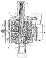
- the thread cutting apparatus shown as a reversible chuck has one Extendable spindle 1 with the shaft 2 for inclusion in the machine tool is in gear connection.
- the pull-out spindle is at the front the clamping head 3 is attached for a tap, not shown.
- the reversible chuck shown is controlled via the controlled thread depth Feed unit of the machine tool retracted, with the drill is pulled out against the action of the length compensation spring 4.
- To unscrew of the tap - the machine tool rotates continuously in the same direction of rotation - a reversal of the direction of rotation via the planetary gear 5 are accomplished, according to the invention by an external drive member 6 takes place.
- the actuation of this external drive member 6 takes place either via a changeover signal triggered by a cam on the clamping head, or a changeover signal, that directly in the feed control of the machine tool with the Reversal signal is generated to retract the feed unit.
- the closing membrane of a compensation chamber 10 in which pressure compensation lines which lead to the occurrence of a reversing movement Negative pressure when pulling out the spindle in the course of retracting the controlled Prevent feed unit.
- the compensation chamber 10 with the movable membrane 9 has the advantage that Penetration of chips, liquid or other dirt from the environment inside the feed is prevented.
Landscapes
- Engineering & Computer Science (AREA)
- Mechanical Engineering (AREA)
- Drilling And Boring (AREA)
- Gripping On Spindles (AREA)
- Percussion Or Vibration Massage (AREA)
- Toys (AREA)
- Load-Engaging Elements For Cranes (AREA)
Abstract
Description
Claims (8)
- Gewindeschneidapparat mit Drehrichtungsumkehr mit einem Planetengetriebe mit einer axial verschiebbaren Umschalteinrichtung zum Umschalten der Drehrichtung eines im Spannkopf einer, vorzugsweise gegen eine Längenausgleichsfeder, ausziehbaren Spindel gehalterten Bohrers nach Erreichen der vorgegebenen Bohrtiefe, insbesondere Reversierfutter mit Druckausgleichsleitungen, die in eine durch eine bewegliche Wand gegenüber der Außenluft abgedichtete Ausgleichskammer einmünden, dadurch gekennzeichnet, dass die Umschalteinrichtung (7) durch ein externes Antriebsglied (6) betätigt wird, das von einem über ein Stellglied erzeugtes Umschaltsignal betätigbar ist.
- Gewindeschneidapparat nach Anspruch 1, dadurch gekennzeichnet, dass das Umschaltsignal von einem Nocken od. dgl. am Spannkopf erzeugt wird.
- Gewindeschneidapparat nach Anspruch 1, dadurch gekennzeichnet, dass das Umschaltsignal von der Vorschubsteuerung erzeugt wird.
- Gewindeschneidapparat nach einem der Ansprüche 1 bis 3, dadurch gekennzeichnet, dass er als Futter zum Synchrongewindeschneiden ohne Spindelauszug ausgebildet ist.
- Gewindeschneidapparat nach einem der Ansprüche 1 bis 4, dadurch gekennzeichnet, dass das externe Antriebsglied (6) ein vorzugsweise zweikammriger Hydraulikzylinder ist.
- Gewindeschneidapparat nach Anspruch 5, dadurch gekennzeichnet, dass das Hydraulikmedium Pressluft ist.
- Gewindeschneidapparat nach Anspruch 5, dadurch gekennzeichnet, dass als Hydraulikmedium das unter Druck stehende Kühlmittel verwendet wird.
- Gewindeschneidapparat nach Anspruch 1 bis 4, dadurch gekennzeichnet, dass das externe Antriebsglied (6) einen Elektromagneten enthält.
Applications Claiming Priority (2)
| Application Number | Priority Date | Filing Date | Title |
|---|---|---|---|
| DE19902901 | 1999-01-26 | ||
| DE19902901A DE19902901B4 (de) | 1999-01-26 | 1999-01-26 | Gewindeschneidapparat mit Drehrichtungsumkehr |
Publications (3)
| Publication Number | Publication Date |
|---|---|
| EP1023963A2 true EP1023963A2 (de) | 2000-08-02 |
| EP1023963A3 EP1023963A3 (de) | 2003-03-12 |
| EP1023963B1 EP1023963B1 (de) | 2004-12-15 |
Family
ID=7895346
Family Applications (1)
| Application Number | Title | Priority Date | Filing Date |
|---|---|---|---|
| EP00100317A Expired - Lifetime EP1023963B1 (de) | 1999-01-26 | 2000-01-07 | Gewindeschneidapparat mit Drehrichtungsumkehr |
Country Status (5)
| Country | Link |
|---|---|
| EP (1) | EP1023963B1 (de) |
| JP (1) | JP2000218435A (de) |
| AT (1) | ATE284769T1 (de) |
| DE (2) | DE19902901B4 (de) |
| ES (1) | ES2228304T3 (de) |
Family Cites Families (4)
| Publication number | Priority date | Publication date | Assignee | Title |
|---|---|---|---|---|
| DE1983895U (de) * | 1966-04-28 | 1968-04-18 | Emil Roeoesli | Gewindeschneidkopf. |
| US4685362A (en) * | 1985-06-19 | 1987-08-11 | Julius Mayer | Quick-mount thread cutting attachment for lathes |
| DE4112467A1 (de) * | 1991-04-17 | 1992-10-22 | Bilz Otto Werkzeug | Gewindeschneidapparat |
| DE19722257C1 (de) * | 1997-05-28 | 1998-08-13 | Glimpel Emuge Werk | Gewindeschneidapparat |
-
1999
- 1999-01-26 DE DE19902901A patent/DE19902901B4/de not_active Expired - Fee Related
-
2000
- 2000-01-07 AT AT00100317T patent/ATE284769T1/de not_active IP Right Cessation
- 2000-01-07 DE DE50008925T patent/DE50008925D1/de not_active Expired - Lifetime
- 2000-01-07 ES ES00100317T patent/ES2228304T3/es not_active Expired - Lifetime
- 2000-01-07 EP EP00100317A patent/EP1023963B1/de not_active Expired - Lifetime
- 2000-01-19 JP JP2000009856A patent/JP2000218435A/ja active Pending
Also Published As
| Publication number | Publication date |
|---|---|
| DE19902901B4 (de) | 2005-06-09 |
| DE19902901A1 (de) | 2000-08-03 |
| DE50008925D1 (de) | 2005-01-20 |
| ATE284769T1 (de) | 2005-01-15 |
| JP2000218435A (ja) | 2000-08-08 |
| ES2228304T3 (es) | 2005-04-16 |
| EP1023963A3 (de) | 2003-03-12 |
| EP1023963B1 (de) | 2004-12-15 |
Similar Documents
| Publication | Publication Date | Title |
|---|---|---|
| DE2165066C3 (de) | ||
| EP2900397B2 (de) | Hand-aufweitgerät | |
| EP2011605B1 (de) | Hydraulisch betätigbares Handwerkzeug | |
| DE2807677C3 (de) | Hydraulisches Schraubgerät | |
| DE102007019434A1 (de) | Handwerkzeugmaschine, insbesondere Bohr- oder Schraubgerät | |
| DE602005002412T2 (de) | Werkzeugmaschine mit mechanischem Vorschub welche ein Ausräumen der Späne ermöglicht | |
| DE102014112908B3 (de) | Spannfutter | |
| CH647579A5 (de) | Steuerung fuer selbstgetriebene rammbohrgeraete. | |
| DE102010021010A1 (de) | Bearbeitungsmaschine | |
| DE3316111A1 (de) | Elektrohandwerkzeug mit steuerung fuer verschiedene funktionen | |
| EP2574874B1 (de) | Schlagwerk für eine Hammereinrichtung und Verfahren zum Offenstellen einer Abstichöffnung | |
| EP2686124A1 (de) | Motorspindel | |
| EP1946892B1 (de) | Schlagschrauber | |
| DE2657711C2 (de) | Hydraulische Schlagvorrichtung, insbesondere für Gesteinsbohrhämmer | |
| EP1023963B1 (de) | Gewindeschneidapparat mit Drehrichtungsumkehr | |
| DE4028304C2 (de) | ||
| EP1524057B1 (de) | Werkzeugtreiberaggregat, insbesondere für den Antrieb eines Gewindefertigungswerkzeugs in einer Gewindefertigungsvorrichtung | |
| EP3477121B1 (de) | Druckbegrenzungseinheit für einen druckübersetzer sowie ein druckübersetzer zum antrieb von hydraulikwerkzeugen | |
| DE102005058156B3 (de) | Hydraulische Spanneinrichtung | |
| EP3292952B1 (de) | Bearbeitungsmaschine mit verbessertem längenmesssystem | |
| DE4445597A1 (de) | Handgeführte Werkzeugmaschine | |
| DE10115864C1 (de) | Fluidbetätigter Zangenspannstock | |
| DE102010008819B4 (de) | Schlagdrehbohrvorrichtung und Verfahren zum Betrieb | |
| EP0720888A1 (de) | Handgeführte Werkzeugmaschine | |
| US6340276B1 (en) | Thread-cutting apparatus with reversal of direction of rotation |
Legal Events
| Date | Code | Title | Description |
|---|---|---|---|
| PUAI | Public reference made under article 153(3) epc to a published international application that has entered the european phase |
Free format text: ORIGINAL CODE: 0009012 |
|
| AK | Designated contracting states |
Kind code of ref document: A2 Designated state(s): AT BE CH CY DE DK ES FI FR GB GR IE IT LI LU MC NL PT SE |
|
| AX | Request for extension of the european patent |
Free format text: AL;LT;LV;MK;RO;SI |
|
| PUAL | Search report despatched |
Free format text: ORIGINAL CODE: 0009013 |
|
| AK | Designated contracting states |
Kind code of ref document: A3 Designated state(s): AT BE CH CY DE DK ES FI FR GB GR IE IT LI LU MC NL PT SE |
|
| AX | Request for extension of the european patent |
Extension state: AL LT LV MK RO SI |
|
| 17P | Request for examination filed |
Effective date: 20030411 |
|
| AKX | Designation fees paid |
Designated state(s): AT BE CH CY DE DK ES FI FR GB GR IE IT LI LU MC NL PT SE |
|
| GRAP | Despatch of communication of intention to grant a patent |
Free format text: ORIGINAL CODE: EPIDOSNIGR1 |
|
| RAP1 | Party data changed (applicant data changed or rights of an application transferred) |
Owner name: EMUGE-WERK RICHARD GLIMPEL GMBH & CO.KG FABRIK |
|
| GRAS | Grant fee paid |
Free format text: ORIGINAL CODE: EPIDOSNIGR3 |
|
| GRAA | (expected) grant |
Free format text: ORIGINAL CODE: 0009210 |
|
| AK | Designated contracting states |
Kind code of ref document: B1 Designated state(s): AT BE CH CY DE DK ES FI FR GB GR IE IT LI LU MC NL PT SE |
|
| PG25 | Lapsed in a contracting state [announced via postgrant information from national office to epo] |
Ref country code: FI Free format text: LAPSE BECAUSE OF FAILURE TO SUBMIT A TRANSLATION OF THE DESCRIPTION OR TO PAY THE FEE WITHIN THE PRESCRIBED TIME-LIMIT Effective date: 20041215 Ref country code: NL Free format text: LAPSE BECAUSE OF FAILURE TO SUBMIT A TRANSLATION OF THE DESCRIPTION OR TO PAY THE FEE WITHIN THE PRESCRIBED TIME-LIMIT Effective date: 20041215 Ref country code: IE Free format text: LAPSE BECAUSE OF FAILURE TO SUBMIT A TRANSLATION OF THE DESCRIPTION OR TO PAY THE FEE WITHIN THE PRESCRIBED TIME-LIMIT Effective date: 20041215 |
|
| REG | Reference to a national code |
Ref country code: CH Ref legal event code: EP Ref country code: GB Ref legal event code: FG4D Free format text: NOT ENGLISH |
|
| PG25 | Lapsed in a contracting state [announced via postgrant information from national office to epo] |
Ref country code: IT Free format text: LAPSE BECAUSE OF NON-PAYMENT OF DUE FEES;WARNING: LAPSES OF ITALIAN PATENTS WITH EFFECTIVE DATE BEFORE 2007 MAY HAVE OCCURRED AT ANY TIME BEFORE 2007. THE CORRECT EFFECTIVE DATE MAY BE DIFFERENT FROM THE ONE RECORDED. Effective date: 20050107 Ref country code: LU Free format text: LAPSE BECAUSE OF NON-PAYMENT OF DUE FEES Effective date: 20050107 Ref country code: CY Free format text: LAPSE BECAUSE OF FAILURE TO SUBMIT A TRANSLATION OF THE DESCRIPTION OR TO PAY THE FEE WITHIN THE PRESCRIBED TIME-LIMIT Effective date: 20050107 |
|
| REG | Reference to a national code |
Ref country code: IE Ref legal event code: FG4D Free format text: GERMAN |
|
| REF | Corresponds to: |
Ref document number: 50008925 Country of ref document: DE Date of ref document: 20050120 Kind code of ref document: P |
|
| PG25 | Lapsed in a contracting state [announced via postgrant information from national office to epo] |
Ref country code: BE Free format text: LAPSE BECAUSE OF NON-PAYMENT OF DUE FEES Effective date: 20050131 Ref country code: MC Free format text: LAPSE BECAUSE OF NON-PAYMENT OF DUE FEES Effective date: 20050131 Ref country code: LI Free format text: LAPSE BECAUSE OF NON-PAYMENT OF DUE FEES Effective date: 20050131 Ref country code: AT Free format text: LAPSE BECAUSE OF NON-PAYMENT OF DUE FEES Effective date: 20050131 Ref country code: CH Free format text: LAPSE BECAUSE OF NON-PAYMENT OF DUE FEES Effective date: 20050131 |
|
| PG25 | Lapsed in a contracting state [announced via postgrant information from national office to epo] |
Ref country code: DK Free format text: LAPSE BECAUSE OF FAILURE TO SUBMIT A TRANSLATION OF THE DESCRIPTION OR TO PAY THE FEE WITHIN THE PRESCRIBED TIME-LIMIT Effective date: 20050315 Ref country code: SE Free format text: LAPSE BECAUSE OF FAILURE TO SUBMIT A TRANSLATION OF THE DESCRIPTION OR TO PAY THE FEE WITHIN THE PRESCRIBED TIME-LIMIT Effective date: 20050315 Ref country code: GR Free format text: LAPSE BECAUSE OF FAILURE TO SUBMIT A TRANSLATION OF THE DESCRIPTION OR TO PAY THE FEE WITHIN THE PRESCRIBED TIME-LIMIT Effective date: 20050315 |
|
| GBT | Gb: translation of ep patent filed (gb section 77(6)(a)/1977) |
Effective date: 20050318 |
|
| REG | Reference to a national code |
Ref country code: ES Ref legal event code: FG2A Ref document number: 2228304 Country of ref document: ES Kind code of ref document: T3 |
|
| NLV1 | Nl: lapsed or annulled due to failure to fulfill the requirements of art. 29p and 29m of the patents act | ||
| REG | Reference to a national code |
Ref country code: IE Ref legal event code: FD4D |
|
| BERE | Be: lapsed |
Owner name: EMUGE-WERK RICHARD GLIMPEL G.M.B.H. & CO.KG FABRIK Effective date: 20050131 |
|
| REG | Reference to a national code |
Ref country code: CH Ref legal event code: PL |
|
| ET | Fr: translation filed | ||
| PLBE | No opposition filed within time limit |
Free format text: ORIGINAL CODE: 0009261 |
|
| STAA | Information on the status of an ep patent application or granted ep patent |
Free format text: STATUS: NO OPPOSITION FILED WITHIN TIME LIMIT |
|
| 26N | No opposition filed |
Effective date: 20050916 |
|
| BERE | Be: lapsed |
Owner name: EMUGE-WERK RICHARD *GLIMPEL G.M.B.H. & CO. K.G. FA Effective date: 20050131 |
|
| PG25 | Lapsed in a contracting state [announced via postgrant information from national office to epo] |
Ref country code: PT Free format text: LAPSE BECAUSE OF NON-PAYMENT OF DUE FEES Effective date: 20050515 |
|
| PGRI | Patent reinstated in contracting state [announced from national office to epo] |
Ref country code: IT Effective date: 20090801 |
|
| PGFP | Annual fee paid to national office [announced via postgrant information from national office to epo] |
Ref country code: IT Payment date: 20120124 Year of fee payment: 13 |
|
| PGFP | Annual fee paid to national office [announced via postgrant information from national office to epo] |
Ref country code: GB Payment date: 20121224 Year of fee payment: 14 Ref country code: ES Payment date: 20121227 Year of fee payment: 14 |
|
| PGFP | Annual fee paid to national office [announced via postgrant information from national office to epo] |
Ref country code: FR Payment date: 20130225 Year of fee payment: 14 Ref country code: DE Payment date: 20130125 Year of fee payment: 14 |
|
| REG | Reference to a national code |
Ref country code: DE Ref legal event code: R119 Ref document number: 50008925 Country of ref document: DE |
|
| GBPC | Gb: european patent ceased through non-payment of renewal fee |
Effective date: 20140107 |
|
| REG | Reference to a national code |
Ref country code: DE Ref legal event code: R119 Ref document number: 50008925 Country of ref document: DE Effective date: 20140801 |
|
| PG25 | Lapsed in a contracting state [announced via postgrant information from national office to epo] |
Ref country code: DE Free format text: LAPSE BECAUSE OF NON-PAYMENT OF DUE FEES Effective date: 20140801 |
|
| REG | Reference to a national code |
Ref country code: FR Ref legal event code: ST Effective date: 20140930 |
|
| PG25 | Lapsed in a contracting state [announced via postgrant information from national office to epo] |
Ref country code: FR Free format text: LAPSE BECAUSE OF NON-PAYMENT OF DUE FEES Effective date: 20140131 Ref country code: GB Free format text: LAPSE BECAUSE OF NON-PAYMENT OF DUE FEES Effective date: 20140107 |
|
| REG | Reference to a national code |
Ref country code: ES Ref legal event code: FD2A Effective date: 20150327 |
|
| PG25 | Lapsed in a contracting state [announced via postgrant information from national office to epo] |
Ref country code: ES Free format text: LAPSE BECAUSE OF NON-PAYMENT OF DUE FEES Effective date: 20140108 |
|
| PG25 | Lapsed in a contracting state [announced via postgrant information from national office to epo] |
Ref country code: IT Free format text: LAPSE BECAUSE OF NON-PAYMENT OF DUE FEES Effective date: 20140107 |