EP1023817B1 - Am körper eines benutzers lagerbare schallwiedergabevorrichtung - Google Patents
Am körper eines benutzers lagerbare schallwiedergabevorrichtung Download PDFInfo
- Publication number
- EP1023817B1 EP1023817B1 EP98950085A EP98950085A EP1023817B1 EP 1023817 B1 EP1023817 B1 EP 1023817B1 EP 98950085 A EP98950085 A EP 98950085A EP 98950085 A EP98950085 A EP 98950085A EP 1023817 B1 EP1023817 B1 EP 1023817B1
- Authority
- EP
- European Patent Office
- Prior art keywords
- sound
- user
- transducers
- head
- reproducing device
- Prior art date
- Legal status (The legal status is an assumption and is not a legal conclusion. Google has not performed a legal analysis and makes no representation as to the accuracy of the status listed.)
- Expired - Lifetime
Links
Images




Classifications
-
- H—ELECTRICITY
- H04—ELECTRIC COMMUNICATION TECHNIQUE
- H04R—LOUDSPEAKERS, MICROPHONES, GRAMOPHONE PICK-UPS OR LIKE ACOUSTIC ELECTROMECHANICAL TRANSDUCERS; ELECTRIC HEARING AIDS; PUBLIC ADDRESS SYSTEMS
- H04R5/00—Stereophonic arrangements
- H04R5/033—Headphones for stereophonic communication
- H04R5/0335—Earpiece support, e.g. headbands or neckrests
-
- H—ELECTRICITY
- H04—ELECTRIC COMMUNICATION TECHNIQUE
- H04R—LOUDSPEAKERS, MICROPHONES, GRAMOPHONE PICK-UPS OR LIKE ACOUSTIC ELECTROMECHANICAL TRANSDUCERS; ELECTRIC HEARING AIDS; PUBLIC ADDRESS SYSTEMS
- H04R2205/00—Details of stereophonic arrangements covered by H04R5/00 but not provided for in any of its subgroups
- H04R2205/024—Positioning of loudspeaker enclosures for spatial sound reproduction
-
- H—ELECTRICITY
- H04—ELECTRIC COMMUNICATION TECHNIQUE
- H04R—LOUDSPEAKERS, MICROPHONES, GRAMOPHONE PICK-UPS OR LIKE ACOUSTIC ELECTROMECHANICAL TRANSDUCERS; ELECTRIC HEARING AIDS; PUBLIC ADDRESS SYSTEMS
- H04R2460/00—Details of hearing devices, i.e. of ear- or headphones covered by H04R1/10 or H04R5/033 but not provided for in any of their subgroups, or of hearing aids covered by H04R25/00 but not provided for in any of its subgroups
- H04R2460/13—Hearing devices using bone conduction transducers
Definitions
- the invention relates to a sound reproduction device for a multi-channel Sound reproduction with a bracket carrying the transducer for storage on the Body of the user, wherein the holder is designed such that it on a body part of the user different from the head can be stored and the sound transducers are adjacent and can be placed at a distance from the user's head, so that the user's head towards the bracket and thus towards the Sound transducers remains freely movable and is based on DE-A-3 214 080.
- a headphone has two ear cups, each of which has at least one a sound transducer is arranged.
- the headphones will be on the user's head put on, so that one ear cup with its open side directly on rests on or surrounds an ear of the user and thus the in the acoustic transducer arranged the acoustic signals directly to the Give ear. In this case, only the left audio signal and only the right audio signal is fed to the right ear.
- DE-A-32 14 080 describes a device for reproducing stereophonic signals known with two speakers that are slanted in front of a listener's ear cups are attached symmetrically with respect to its median plane, and the two Loudspeakers on one that is supported on the neck and trunk of the listener Bracket are attached so that the head of the handset is relative to the speakers remains flexible.
- the present invention has for its object the sound reproduction device of the type mentioned in the introduction such that a qualitative high quality sound reproduction with improved spatial allocation, in particular is achievable with multi-channel sound reproduction, without that with loudspeaker systems installation problems occurring and without being influenced by the room acoustics, wherein the sound reproduction device in particular take up little space and should be easy to handle.
- the left and the right ear can record all played channels, so that the individual Transfer function of a user's head included in the playback becomes.
- the Sound incidence clearly from the listener be determined.
- This is also supported by the fact that with fixed Device a head rotation is made possible, which as in the natural Listening to the location of a sound source is simplified.
- a so-called head-related Sound reproducing device created by at the body of the User mounted bracket or the transducer itself not directly rest on the head, but are arranged at a distance from it and thus allow a rotation of the head, whereby the or the Do not move the transducer with your head.
- the Construction according to the invention achieve an exact spatial assignment.
- the sound reproduction device take advantage of the overall transfer function of the head while this is not possible with headphones because headphones are not “headphones”, but rather “earphones” because their ear cups are directly on the Lay on the ear or enclose it and thus the ones in it Sound transducers deliver the acoustic signals directly to the ear.
- Sound transducers deliver the acoustic signals directly to the ear.
- the invention allows sound reproduction at a very high level Noise perception without the environment and especially the Neighbors are disturbed because the transducers are very close to the ears are arranged by the user and therefore already relatively low sound pressures on the playback converter are sufficient to achieve a high user To achieve volume impression.
- a particular advantage of the playback device is that in its Bracket an electronic circuit for processing the electrical Signals for the sound transducer is integrated. This is made possible precisely by that the holder is not supported on the head, but e.g. on the much stronger shoulders.
- the integration of the circuit in the Bracket eliminates the need for a corresponding external device and makes it easier Manageability of the sound reproduction device essential.
- a great advantage of the circuit integrated in the holder is that the Circuit filters and subcircuits to equalize the transducers can have. This allows the transducers to be particularly effective Way to be electronically equalized, resulting in increased playback quality allows.
- a circuit having amplifier stages is particularly preferred, so that the sound reproducing device directly to a signal source, such as a CD player, can be connected.
- the circuit is a partial circuit in a preferred embodiment for decoding encrypted multichannel signals they are used, for example, to decrypt Dolby Surround signals and make a corresponding external decoder superfluous. In this If it is enough, the sound reproduction device directly to a CD player connect, for example using the Dolby Surround method recorded CDs in true Dolby Surround quality without any additional equipment listen.
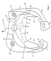
- the first embodiment of the sound reproduction device shown in FIG. 1 has a housing or frame 2, which consists of a rear part 4 and two there are curved side parts 5 and 6 adjoining on both sides, which end in free end sections 7 and 8.
- the frame 2 is thus formed as a shaped body, the top view (see Fig. 2) essentially the shape of an interrupted "O" or a "U” with cranked inwards has free ends.
- front first and second Sound transducers 10 and 11 rear third and fourth sound transducers 12 and 13 and a rear woofer 14 is arranged. So that serves Frame 2 for holding the transducers 10 to 14.
- the transducers 10 to 14 form a multi-channel Dolby Surround playback system, whereby the front first and second sound converters 10 and 11 as main converters to reproduce the front right and left information and the rear third and fourth sound transducers 12 and 13 as rear transducers to play the additional room information (surround channel) are provided, while the rear low-frequency transducer 14 the low-frequency Share reflects.
- acoustic in frame 2 Lines 15 and 16 formed, one of which is an acoustic line 15 from the rear bass transducer 14 into one side part 5 extends and there adjacent to the rear third transducer 12 in an internally arranged outlet opening 17 ends and the another acoustic line 16 from the rear woofer 14 in the extends other side part 6 and there adjacent to the rear fourth Sound transducer 13 also in an inward opening 18 ends.
- the frame 2 there is also an electronic circuit 40 to which the Sound transducers 10 to 14 via electrical lines 42, 43, 44, 45 and 46 are connected. Another electrical line 47 is used for connection the sound reproducing device to a signal source.
- the control circuit 40 can have different subcircuits, namely those for equalizing the individual sound transducers 10 to 14, such for decoding an encrypted multi-channel audio signal and the like to amplify the signals for the individual transducers.
- the encrypted Multi-channel audio signal is through line 47 of circuit 40 fed and decoded and amplified there.
- the signal for the individual sound transducers taking into account those for the sound transducers characteristic distortions processed so that the sound transducers in Play a largely undistorted signal.
- the sound reproducing device is that the sound signals the circuit 40 'is not supplied via a line 47, but wireless.
- the circuit has a corresponding receiver 48, e.g. an infrared receiver or RF receiver.
- a corresponding receiver 48 e.g. an infrared receiver or RF receiver.
- that is Switching also with its own battery-powered energy supply fitted. This makes it the wearer of the sound reproducing device possible to move freely in the room.
- the transducers 10 to 14 are arranged recessed, in order to avoid edges that would otherwise have sound reflections and thus also interference with that emitted directly by the sound transducer Cause sound.
- the first to fourth sound transducers 10-13 are oriented so that they the sound by correspondingly trained on the inside of the frame 2 (Not shown in more detail) openings in the 2 enclosed by the frame Deliver interior, the frame 2 at least at those openings, but preferably as a whole of one (not shown) Textile layer or other protective layer is covered, which however not is imperative.
- the carrier 2 itself consists of a highly damping Material so that it is not itself used for sound generation and conduction contributes.
- the frame 2 is designed as a molded body however, other constructions for mounting the transducers 10-14 and formation of the acoustic lines 15 and 16 conceivable. If desired, can also dispense with the acoustic lines 15 and 16 become; this naturally also applies in principle to the number and training of the individual sound transducers.
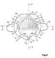
- FIGS. 2 and 3 now show how the previously described embodiment the sound reproducing device mounted on a user's body becomes.
- the frame 2 is not only used to arrange the sound transducers 10 - 14, but also for storing this arrangement on the body of a user by using the undersides 5a and 6a of the side parts 5 and 6 (see FIG. 1) rests on the shoulders 20 of the user while it is with the underside 4a of the rear part 4 (see FIG. 1) not necessarily on Back of the user is supported.
- the frame 2 is designed and on the shoulders 2 and possibly on the back of the user and fixable that the frame 2 a short distance from the head 22 of the user has and thus the head 22 remains freely movable.
- the frame can also be designed so that it is on another part of the body is storable. It is only important that it is different from the head 22 Body part of the user can be stored so that the head 22nd compared to the frame 2 and thus compared to those arranged therein Sound transducers 10-14 and outlet openings 17 and 18 of the acoustic Lines 15 and 16 remain freely movable.
- the frame 2 of the embodiment shown there has the shape a collar when it rests on the shoulders 20 of the user. Therefore the described sound reproduction device can also be used as a "hearing collar" be designated.
- the storage is preferably designed so that the focus of the Central storage in the support area between the shoulders of the user formed. If necessary, weights 7 and 8 can be accommodated for this purpose be (not shown).
- the sound transducers 10 - 14 and the outlet openings 17 and 18 of the acoustic lines 15 and 16 arranged in the frame 2 so that when the frame 2 is mounted on the body of the user, the front first and second transducer 10 and 1 1 in front of the frontal plane F one on the head 22 user-related coordinate system in the area of the chin below ear level and the rear third and fourth transducers 12 and 13 lie behind the frontal plane F and the outlet openings 17 and 18 of the acoustic lines 15 and 16 just below the ears 24 and 25 are arranged while the rear woofer 14 behind the head 22 lies, as can be seen in FIGS. 2 and 3.
- front first and second transducers 10 and 11 and the rear third and fourth sound transducers 12 and 13 each symmetrical to the median plane M of the coordinate system related to the user's head 22 arranged while the rear woofer 14th lies in the median plane M, as can also be seen in FIG. 2.
- the described sound reproduction device accordingly forms a head-related one multi-channel playback system.
- the transducers 10-14 are over arranged around the head 22, but not directly on the head 22 abut, but arranged at least a short distance from it are and thus do not move when the head 22 is rotated.
- the user's head 22 is thus free himself, which leads to how with loudspeakers installed in the room, a spatial reproduction is made possible. Due to the spatial distance of the transducers from the Ears 24 and 25 will transfer the user head into that Sound field included and there is also a structure-borne sound transmission instead, so that the perception of the reproduced sound for the User sounds more "natural".
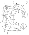
- FIGS. 4 and 5 show a second embodiment of the sound reproduction device shown, which differ from the first embodiment according to the figures 1 to 3 differs in that in addition a front sound transducer 30 is arranged, the on the shoulders 20 of the user Frame 2 approximately in the median plane M in the area of the chin of the user lies.
- a front sound transducer 30 is arranged, the on the shoulders 20 of the user Frame 2 approximately in the median plane M in the area of the chin of the user lies.
- this additional sound transducer 30 is one End section 7 compared to the first embodiment with an extension 7a provided and accordingly extended or the device is closed towards the front (O-shaped).
- Sound transducer 30 is also connected to circuit 40 'via a line 49. connected, through which the signal for the transducer 30 to the Fig. 1 described way is processed.
- the sound reproduction device can also 4 prepared for wireless operation become. This is shown in Fig. 4a.
Landscapes
- Physics & Mathematics (AREA)
- Engineering & Computer Science (AREA)
- Acoustics & Sound (AREA)
- Signal Processing (AREA)
- Stereophonic System (AREA)
- Details Of Audible-Bandwidth Transducers (AREA)
- Electrophonic Musical Instruments (AREA)
Description
- Fig. 1
- eine erste Ausführung der Schallwiedergabevorrichtung in perspektivischer Darstellung;
- Fig. 1a
- eine alternative Ausführungsform der Schallwiedergabevorrichtung aus Fig. 1 für den drahtlosen Tonsignalempfang;
- Fig. 2
- die Ausführung gemäß Fig. 1 (auf den Schultern eines Benutzers gelagert) in Draufsicht;
- Fig. 3
- die Ausführung gemäß Fig. 1 (auf den Schultern eines Benutzers gelagert) in Vorderansicht;
- Fig. 4
- eine zweite Ausführung der Schallwiedergabevorrichtung;
- Fig. 4a
- eine alternative Ausführungsform der Schallwiedergabevorrichtung aus Fig. 1 für den drahtlosen Tonsignalempfang;
- Fig. 5
- die Ausführung gemäß Fig. 4 (auf den Schultern eines Benutzers gelagert) in Draufsicht;
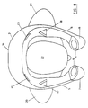
- Fig. 6
- eine Vorderansicht der Schallwiedergabevorrichtung;
- Fig. 7
- eine Seitenansicht mit einem Teilschnitt durch die Schallwiedergabevorrichtung; und
- Fig. 8
- eine Ansicht von oben der Schallwiedergabevorrichtung.
Claims (5)
- Schallwiedergabevorrichtung für eine mehrkanalige Schallwiedergabe mit einer Schallwandler tragenden Halterung (2) zur Lagerung am Körper des Benutzers, wobei die Halterung (2) derart ausgebildet ist, dass sie an einem vom Kopf (22) unterschiedlichen Körperteil (20) des Benutzers lagerbar und dabei die Schallwandler (10; 11; 12; 13; 14; 30) benachbart und in einem Abstand zum Kopf (22) des Benutzers plazierbar sind, so dass der Kopf (22) des Benutzers gegenüber der Halterung (2) und somit gegenüber den Schallwandlern (10; 11; 12; 13; 14; 30) frei bewegbar bleibt,
dadurch gekennzeichnet, dass mindestens drei von je einem elektrischen Signal angesteuerte Schallwandler (10; 11; 12; 13; 14; 30) vorgesehen sind, von denen ein Schallwandler (13) dem linken Ohr und ein Schallwandler (12) dem rechten Ohr zugeordnet ist und mindestens ein weiterer Schallwandler (10; 11; 30) vor dem Gesicht des Benutzers liegt, und dass die Halterung eine elektronische Schaltung zur Aufbereitung der elektrischen Signale trägt. - Schallwiedergabevorrichtung nach Anspruch 1,
dadurch gekennzeichnet, dass die Schaltung Hoch- und Tiefpaßfilter aufweist. - Schallwiedergabevorrichtung nach Anspruch 1 oder 2,
dadurch gekennzeichnet, dass die Schaltung Verstärkerstufen aufweist. - Schallwiedergabevorrichtung nach einem der Ansprüche 1 bis 3,
dadurch gekennzeichnet, dass die Schaltung eine Teilschaltung zur Entzerrung der Schallwandler aufweist. - Schallwiedergabevorrichtung nach einem der Ansprüche 1 bis 4,
dadurch gekennzeichnet, dass die Schaltung eine Teilschaltung zum Decodieren verschlüsselter Mehrkanalsignale aufweist.
Applications Claiming Priority (3)
| Application Number | Priority Date | Filing Date | Title |
|---|---|---|---|
| DE1997145574 DE19745574A1 (de) | 1996-04-26 | 1997-10-15 | Am Körper eines Benutzers lagerbare Schallwiedergabevorrichtung |
| DE19745574 | 1997-10-15 | ||
| PCT/EP1998/006138 WO1999020077A1 (de) | 1997-10-15 | 1998-09-26 | Am körper eines benutzers lagerbare schallwiedergabevorrichtung |
Publications (2)
| Publication Number | Publication Date |
|---|---|
| EP1023817A1 EP1023817A1 (de) | 2000-08-02 |
| EP1023817B1 true EP1023817B1 (de) | 2002-06-26 |
Family
ID=7845623
Family Applications (1)
| Application Number | Title | Priority Date | Filing Date |
|---|---|---|---|
| EP98950085A Expired - Lifetime EP1023817B1 (de) | 1997-10-15 | 1998-09-26 | Am körper eines benutzers lagerbare schallwiedergabevorrichtung |
Country Status (6)
| Country | Link |
|---|---|
| EP (1) | EP1023817B1 (de) |
| JP (1) | JP2001521299A (de) |
| AT (1) | ATE219877T1 (de) |
| AU (1) | AU9628498A (de) |
| DE (1) | DE59804603D1 (de) |
| WO (1) | WO1999020077A1 (de) |
Families Citing this family (1)
| Publication number | Priority date | Publication date | Assignee | Title |
|---|---|---|---|---|
| ATE275808T1 (de) * | 1999-07-20 | 2004-09-15 | Florian Meinhard Koenig | Kopfhörer mit einstellbarer ortbarkeit des von ihm erzeugten schallereignisses |
Family Cites Families (6)
| Publication number | Priority date | Publication date | Assignee | Title |
|---|---|---|---|---|
| US3900707A (en) * | 1973-06-06 | 1975-08-19 | Hear Muffs | Speaker apparatus |
| JPS62299200A (ja) * | 1986-06-18 | 1987-12-26 | Matsushita Electric Ind Co Ltd | ステレオヘツドホン |
| DE3709397C2 (de) * | 1987-03-21 | 1997-10-09 | Head Acoustics Gmbh | Verfahren zur Filterung von Schallsignalen |
| FR2652698A1 (fr) * | 1989-10-02 | 1991-04-05 | Sgs Thomson Microelectronics | Decodeur pour decoder un son crypte. |
| JPH0437303A (ja) * | 1990-06-01 | 1992-02-07 | Matsushita Electric Ind Co Ltd | 低周波増幅器 |
| DE19616870A1 (de) * | 1996-04-26 | 1997-10-30 | Sennheiser Electronic | Am Körper eines Benutzers lagerbare Schallwiedergabevorrichtung |
-
1998
- 1998-09-26 JP JP2000516505A patent/JP2001521299A/ja not_active Abandoned
- 1998-09-26 WO PCT/EP1998/006138 patent/WO1999020077A1/de not_active Ceased
- 1998-09-26 DE DE59804603T patent/DE59804603D1/de not_active Expired - Fee Related
- 1998-09-26 AT AT98950085T patent/ATE219877T1/de not_active IP Right Cessation
- 1998-09-26 AU AU96284/98A patent/AU9628498A/en not_active Abandoned
- 1998-09-26 EP EP98950085A patent/EP1023817B1/de not_active Expired - Lifetime
Also Published As
| Publication number | Publication date |
|---|---|
| AU9628498A (en) | 1999-05-03 |
| EP1023817A1 (de) | 2000-08-02 |
| DE59804603D1 (de) | 2002-08-01 |
| JP2001521299A (ja) | 2001-11-06 |
| ATE219877T1 (de) | 2002-07-15 |
| WO1999020077A1 (de) | 1999-04-22 |
Similar Documents
| Publication | Publication Date | Title |
|---|---|---|
| EP0895702B1 (de) | Am körper eines benutzers lagerbare schallwiedergabevorrichtung | |
| DE19981794B3 (de) | Akustische Vorrichtung und Kopfhörer | |
| DE69027731T2 (de) | Elektroakustischer Wandler und Tonwiedergabesystem | |
| DE2548597C2 (de) | ||
| DE3786040T2 (de) | Stereophonischer Lautsprecher. | |
| DE2813000A1 (de) | Guertel mit geraeten zum anhoeren von reproduzierter musik | |
| DE7632349U1 (de) | Tonwiedergabegeraet | |
| DE2525642C3 (de) | Vorrichtung für die stereophonische Aufnahme und Kontrolle von Schallereignissen | |
| DE60125983T2 (de) | Im fahrzeug angebrachter stereo-schallfeldwandler | |
| EP3677053B1 (de) | Lautsprechersystem für raumklang mit unterdrückung unerwünschten direktschalls | |
| EP0040739A1 (de) | Vorrichtung für die Wiedergabe einer Tonaufnahme über Kopfhörer | |
| DE2303194C2 (de) | Hörhilfsgerät für Schwerhörige oder Hörbehinderte | |
| DE102021200552B4 (de) | Am Kopf tragbarer Schallerzeuger und Verfahren zum Betreiben eines Schallerzeugers | |
| DE2941692A1 (de) | Verfahren und vorrichtung zur tonwiedergabe | |
| DE2344259C3 (de) | Mehrkanalsystem zur Aufnahme und Wiedergabe stereofoner Darbietungen | |
| EP1071309B1 (de) | Kopfhörer mit einstellbarer Ortbarkeit des von ihm erzeugten Schallereignisses | |
| EP0775431B1 (de) | Mehrkanalkopfhörer mit gesteuerter abstrahlcharakteristik | |
| EP1023817A1 (de) | Am körper eines benutzers lagerbare schallwiedergabevorrichtung | |
| DE19926552B4 (de) | Kopfhörer mit Mikrofon | |
| DE2557516C3 (de) | Kopfhörersystem | |
| DE2652101A1 (de) | Einrichtung mit drahtloser uebertragung eines tonsignales | |
| DE19745574A1 (de) | Am Körper eines Benutzers lagerbare Schallwiedergabevorrichtung | |
| DE19645307B4 (de) | Kopfhörer/Hörhilfe | |
| DE4425759A1 (de) | Tragbare Hörhilfe | |
| AT389610B (de) | Stereophonische aufnahmeeinrichtung zur verbesserung des raeumlichen hoerens |
Legal Events
| Date | Code | Title | Description |
|---|---|---|---|
| PUAI | Public reference made under article 153(3) epc to a published international application that has entered the european phase |
Free format text: ORIGINAL CODE: 0009012 |
|
| 17P | Request for examination filed |
Effective date: 20000515 |
|
| AK | Designated contracting states |
Kind code of ref document: A1 Designated state(s): AT CH DE DK ES FR GB IT LI NL SE |
|
| 17Q | First examination report despatched |
Effective date: 20000929 |
|
| GRAG | Despatch of communication of intention to grant |
Free format text: ORIGINAL CODE: EPIDOS AGRA |
|
| GRAG | Despatch of communication of intention to grant |
Free format text: ORIGINAL CODE: EPIDOS AGRA |
|
| GRAH | Despatch of communication of intention to grant a patent |
Free format text: ORIGINAL CODE: EPIDOS IGRA |
|
| GRAH | Despatch of communication of intention to grant a patent |
Free format text: ORIGINAL CODE: EPIDOS IGRA |
|
| GRAA | (expected) grant |
Free format text: ORIGINAL CODE: 0009210 |
|
| AK | Designated contracting states |
Kind code of ref document: B1 Designated state(s): AT CH DE DK ES FR GB IT LI NL SE |
|
| PG25 | Lapsed in a contracting state [announced via postgrant information from national office to epo] |
Ref country code: NL Free format text: LAPSE BECAUSE OF FAILURE TO SUBMIT A TRANSLATION OF THE DESCRIPTION OR TO PAY THE FEE WITHIN THE PRESCRIBED TIME-LIMIT Effective date: 20020626 Ref country code: IT Free format text: LAPSE BECAUSE OF FAILURE TO SUBMIT A TRANSLATION OF THE DESCRIPTION OR TO PAY THE FEE WITHIN THE PRESCRIBED TIME-LIMIT;WARNING: LAPSES OF ITALIAN PATENTS WITH EFFECTIVE DATE BEFORE 2007 MAY HAVE OCCURRED AT ANY TIME BEFORE 2007. THE CORRECT EFFECTIVE DATE MAY BE DIFFERENT FROM THE ONE RECORDED. Effective date: 20020626 Ref country code: GB Free format text: LAPSE BECAUSE OF FAILURE TO SUBMIT A TRANSLATION OF THE DESCRIPTION OR TO PAY THE FEE WITHIN THE PRESCRIBED TIME-LIMIT Effective date: 20020626 Ref country code: FR Free format text: LAPSE BECAUSE OF FAILURE TO SUBMIT A TRANSLATION OF THE DESCRIPTION OR TO PAY THE FEE WITHIN THE PRESCRIBED TIME-LIMIT Effective date: 20020626 |
|
| REF | Corresponds to: |
Ref document number: 219877 Country of ref document: AT Date of ref document: 20020715 Kind code of ref document: T |
|
| REG | Reference to a national code |
Ref country code: GB Ref legal event code: FG4D Free format text: NOT ENGLISH |
|
| REG | Reference to a national code |
Ref country code: CH Ref legal event code: EP |
|
| REF | Corresponds to: |
Ref document number: 59804603 Country of ref document: DE Date of ref document: 20020801 |
|
| PG25 | Lapsed in a contracting state [announced via postgrant information from national office to epo] |
Ref country code: SE Free format text: LAPSE BECAUSE OF FAILURE TO SUBMIT A TRANSLATION OF THE DESCRIPTION OR TO PAY THE FEE WITHIN THE PRESCRIBED TIME-LIMIT Effective date: 20020926 Ref country code: DK Free format text: LAPSE BECAUSE OF FAILURE TO SUBMIT A TRANSLATION OF THE DESCRIPTION OR TO PAY THE FEE WITHIN THE PRESCRIBED TIME-LIMIT Effective date: 20020926 Ref country code: AT Free format text: LAPSE BECAUSE OF NON-PAYMENT OF DUE FEES Effective date: 20020926 |
|
| PG25 | Lapsed in a contracting state [announced via postgrant information from national office to epo] |
Ref country code: LI Free format text: LAPSE BECAUSE OF NON-PAYMENT OF DUE FEES Effective date: 20020930 Ref country code: CH Free format text: LAPSE BECAUSE OF NON-PAYMENT OF DUE FEES Effective date: 20020930 |
|
| NLV1 | Nl: lapsed or annulled due to failure to fulfill the requirements of art. 29p and 29m of the patents act | ||
| PG25 | Lapsed in a contracting state [announced via postgrant information from national office to epo] |
Ref country code: ES Free format text: LAPSE BECAUSE OF FAILURE TO SUBMIT A TRANSLATION OF THE DESCRIPTION OR TO PAY THE FEE WITHIN THE PRESCRIBED TIME-LIMIT Effective date: 20021220 |
|
| GBV | Gb: ep patent (uk) treated as always having been void in accordance with gb section 77(7)/1977 [no translation filed] |
Effective date: 20020626 |
|
| EN | Fr: translation not filed | ||
| PLBE | No opposition filed within time limit |
Free format text: ORIGINAL CODE: 0009261 |
|
| STAA | Information on the status of an ep patent application or granted ep patent |
Free format text: STATUS: NO OPPOSITION FILED WITHIN TIME LIMIT |
|
| REG | Reference to a national code |
Ref country code: CH Ref legal event code: PL |
|
| 26N | No opposition filed |
Effective date: 20030327 |
|
| PGFP | Annual fee paid to national office [announced via postgrant information from national office to epo] |
Ref country code: DE Payment date: 20060912 Year of fee payment: 9 |
|
| PG25 | Lapsed in a contracting state [announced via postgrant information from national office to epo] |
Ref country code: DE Free format text: LAPSE BECAUSE OF NON-PAYMENT OF DUE FEES Effective date: 20080401 |