EP1022634A1 - Kartusche für Sanitärarmaturen - Google Patents
Kartusche für Sanitärarmaturen Download PDFInfo
- Publication number
- EP1022634A1 EP1022634A1 EP20000100534 EP00100534A EP1022634A1 EP 1022634 A1 EP1022634 A1 EP 1022634A1 EP 20000100534 EP20000100534 EP 20000100534 EP 00100534 A EP00100534 A EP 00100534A EP 1022634 A1 EP1022634 A1 EP 1022634A1
- Authority
- EP
- European Patent Office
- Prior art keywords
- cartridge
- housing
- distributor
- control device
- distributor housing
- Prior art date
- Legal status (The legal status is an assumption and is not a legal conclusion. Google has not performed a legal analysis and makes no representation as to the accuracy of the status listed.)
- Granted
Links
- XLYOFNOQVPJJNP-UHFFFAOYSA-N water Substances O XLYOFNOQVPJJNP-UHFFFAOYSA-N 0.000 claims abstract description 13
- 230000001681 protective effect Effects 0.000 description 2
- 238000010276 construction Methods 0.000 description 1
- 230000001419 dependent effect Effects 0.000 description 1
- 230000000694 effects Effects 0.000 description 1
- 238000004519 manufacturing process Methods 0.000 description 1
Images
Classifications
-
- G—PHYSICS
- G05—CONTROLLING; REGULATING
- G05D—SYSTEMS FOR CONTROLLING OR REGULATING NON-ELECTRIC VARIABLES
- G05D23/00—Control of temperature
- G05D23/01—Control of temperature without auxiliary power
- G05D23/13—Control of temperature without auxiliary power by varying the mixing ratio of two fluids having different temperatures
- G05D23/1306—Control of temperature without auxiliary power by varying the mixing ratio of two fluids having different temperatures for liquids
- G05D23/132—Control of temperature without auxiliary power by varying the mixing ratio of two fluids having different temperatures for liquids with temperature sensing element
- G05D23/134—Control of temperature without auxiliary power by varying the mixing ratio of two fluids having different temperatures for liquids with temperature sensing element measuring the temperature of mixed fluid
- G05D23/1346—Control of temperature without auxiliary power by varying the mixing ratio of two fluids having different temperatures for liquids with temperature sensing element measuring the temperature of mixed fluid with manual temperature setting means
- G05D23/1353—Control of temperature without auxiliary power by varying the mixing ratio of two fluids having different temperatures for liquids with temperature sensing element measuring the temperature of mixed fluid with manual temperature setting means combined with flow controlling means
-
- Y—GENERAL TAGGING OF NEW TECHNOLOGICAL DEVELOPMENTS; GENERAL TAGGING OF CROSS-SECTIONAL TECHNOLOGIES SPANNING OVER SEVERAL SECTIONS OF THE IPC; TECHNICAL SUBJECTS COVERED BY FORMER USPC CROSS-REFERENCE ART COLLECTIONS [XRACs] AND DIGESTS
- Y10—TECHNICAL SUBJECTS COVERED BY FORMER USPC
- Y10T—TECHNICAL SUBJECTS COVERED BY FORMER US CLASSIFICATION
- Y10T137/00—Fluid handling
- Y10T137/5109—Convertible
Definitions
- the invention has for its object to a cartridge create, which offers the possibility with compact construction different types of sanitary fittings with low Realizing effort.
- the invention proposes a cartridge with the features of claim 1. Training the invention are the subject of the dependent claims, the Wording as well as the wording of the summary Reference is made to the content of the description.
- the bottom of the cartridge housing is used for the Connection between the water channels of the control device and manufacture the channels in the valve body.
- the Versatility of the cartridge proposed by the invention will be further improved if the floor is also replaced can be. By exchanging the floor it is both possible to change a cartridge and in the same Arrange valve body, as well as the unchanged cartridge to use for a different valve.
- a further development of the invention can be provided be that the rotary motion of the junction box through an attack is limited.
- it is special makes sense, for example, on the distributor housing attached stop with part of the control device to work together, the effect of a different Characteristic of the valve is exchanged.
- a thermostat can be arranged in the cartridge his.
- a distributor is arranged, the water channels through which the water introduced into the valve flows to the thermostat, for example, and from there as well back to the control device and the cartridge bottom back.
- the invention proposes that the water axially into the Cartridge arrives and also leaves it axially.
- the cartridge saves space and is built compactly and also in a compact valve body can be used. Is in the axial direction usually plenty of space available.
- the control device has a disc system.
- Such disk systems are known for single-lever mixer valves and other valves.
- she usually contain a fixed control disc, the is also referred to as a distributor disc, as well as one with this movable control disc in contact.
- the invention here proposes that the movable Control disc can be rotated about a fixed axis can.
- the twist can be directly through the distributor housing respectively.
- An actuator can be used with the distributor housing for example in the form of a twist grip stand.
- control device can control the quantity have, so the actuation to a change of the flow cross section and thus to a change in Amount of escaping from the sanitary fitting per unit of time Water leads.
- control device it is also possible for the control device to have a Switching device for switching between different Contains outlets from the fitting.
- the switching device can in training with the same actuator are operated with which the quantity control is also operated becomes.
- the actuating element also in the is operated in the same way as to change the quantity setting. For example, a twist over a certain position beyond switching the outlets lead, this position preferably in one position in which the several outlets are closed.
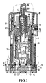
- Fig. 1 shows in a through the axis of the valve Axial section the structure of a cartridge according to the invention.
- the cartridge contains a cartridge housing 1, which as cylindrical sleeve is formed on the outside and has a shoulder 2, 3 on the inside. With help the outer shoulder 2, the cartridge housing 1 in fix a valve body, for example with the help a plate 4 which is screwed by a screw 5. This is shown schematically at the bottom left in FIG. 1.
- the Cartridge housing 1 is surrounded by a protective sleeve 6 which visually covers the cartridge.
- the protective sleeve 6 extends to under the edge 7 of a rotary handle 8, which for actuating the Cartridge is used.
- a distributor housing 9 is rotatable in the cartridge housing 1 stored, which is designed as a cylindrical sleeve. Between the distributor housing 9 and the cartridge housing 1 a slide and guide ring 10 is used. The axial position of the distributor housing 9 is a concern Shoulder 11 on the inner shoulder 3 of the cartridge housing 1 set in one direction. In the other direction the determination takes place in that the distributor housing 9 rests on a fixed control disc 12, the one Forms part of a control device 13 of the cartridge. The fixed control disc 12 rests on a floor 14, the axially secured at the outer end of the cartridge housing 1 is.
- the distributor housing 9 is via the most of its longitudinal extent as a cylindrical sleeve formed, on which assigned to the control device 13 End there is an increase in diameter, which the already mentioned shoulder 11 forms.
- the distributor housing 9 has at the opposite end an internal thread 15, which is arranged at one point, where the distributor housing 9 has a larger wall thickness.
- the internal thread 15 does not extend all the way to the end of the distributor housing 9.
- the insert has one Storage on in which a rotary spindle 19 is rotatably mounted is.
- the rotary spindle 19 is axially secured and projects with a toothed approach 20 out of the insert 18.
- the Turning spindle 19 is hollow on the inside, and in this Cavity 47, a sleeve body 21 is axially displaceable housed.
- the sleeve body 21 has on its outside outside of the rotary spindle 19 an outward Flange 22 on.
- the insert 18 contains an internal thread 23 with which a nut element 24 is engaged.
- the nut member 24 is axially movable, but secured against rotation on the outside the rotating spindle 19 out.
- a rotation of the rotating spindle 19 leads to a rotation of the nut 24, which is due to the Engaging in the internal thread 23 then shifts axially and rests on the flange 22.
- a thermostat 25 is accommodated in the sleeve body 21, which is clamped between two springs 26, 27.
- the spring 27 presses the thermostat into the sleeve body 21 so that it also shifted towards the upper end in FIG. 1 becomes.
- a second handle 28 arranged with the toothed approach 20 is in rotational engagement.
- the thermostat 25 moves a valve body 29 which in known manner two annular slots as valve seats opens and closes.
- the thermostat 25 is with its valve body 29 and the associated valve seats in a cage arranged, which is fastened within a distributor 30.
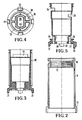
- This distributor 30 forms water channels, which in the Water entering the cartridge to the thermostat 25 and from this again to the control device 13. Details the distributor can be seen from FIGS. 3 to 5, to which reference is now made.
- the distributor 30 is approximately sleeve-shaped and so dimensioned so that it is interposed with a seal in the distributor housing 9 inserted from below in Fig. 2 can be.
- the distributor 30 contains two in its cylindrical region Slits 33, 34 that are in different axial positions are arranged. They serve to keep the water flowing in reaches the thermostat 25. One of the two slots is for the cold water and the other for the warm water certainly.
- the distributor is arranged in the interior of the distributor housing 9, and inside the manifold 30 the thermostat 25. Then in on the front side 36 of the distributor 30 Fig. 1 to see rotatable control disc 41 with the intermediate layer the seal 38 applied.
- the correct rotational position this movable control disc 41 is different by notches Width guaranteed with the projections 31 of the distributor 30 cooperate.
- On the rotatable Control disc 41 then becomes the fixed control disc 12 hung up, their correct position also by notches guaranteed different width in their outer circumference becomes.
- the extended neck 32 of the manifold 30 then comes in an arcuate groove 42 of the fixed control disc 12 to lie, thereby limiting the angle of rotation for the rotation the control disc is effected.
- the groove 42 extends only over part of an arc, for example over 90 degrees.
- the twist grip 8 is attached to the distributor housing by means of a screw 43 9 screwed tight.
- the screw 43 engages its inward end into the groove 16. Thereby the axial position of the rotary handle 8 is fixed. A Rotation of the rotary handle 8 leads to a rotation of the
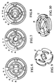
- Figure 6 shows an arrangement in which both in the fixed as well as in the rotatable control disc two arcuate slots are available as through openings are.
- the distributor can be turned through an angle. With increasing rotation, the cross section of the inlet openings becomes and the outlet openings further enlarged so that this rotary movement represents a quantity control.
- the associated rotatable control disk 41 is shown in FIG. 9. The side seen in FIG. 9 is that in FIG. 1 upper side.
- Fig. 7 shows an arrangement with which an outlet in its Amount and temperature can be controlled.
- cold water is first Bypass issued while increasing opening at the same time the temperature of the water also rises.
- Fig. 8 shows a possibility in which starting from a Middle position by turning to the right a first outlet is opened while twisting from the closed Position to the left opens a second outlet.
- Fig. 10 shows in perspective the control disc of the sanitary fitting of Fig. 7.
- the fixed control disc 12 has an outlet opening 46 which is asymmetrical, to form a bypass.
Landscapes
- Physics & Mathematics (AREA)
- General Physics & Mathematics (AREA)
- Engineering & Computer Science (AREA)
- Automation & Control Theory (AREA)
- Multiple-Way Valves (AREA)
- Separation Using Semi-Permeable Membranes (AREA)
- Bidet-Like Cleaning Device And Other Flush Toilet Accessories (AREA)
Abstract
Description
- Fig. 1
- einen Axialschnitt durch eine Kartusche nach der Erfindung;
- Fig. 2
- einen Axialschnitt durch ein Verteilergehäuse;
- Fig. 3
- einen Axialschnitt durch einen in dem Verteilergehäuse angeordneten Verteiler;
- Fig. 4
- die Stirnansicht des Verteilers der Fig. 3;
- Fig. 5
- einen zweiten Axialschnitt durch den Verteiler der Fig. 2 in einer anderen Ebene;
- Fig. 6
- schematisch die Steuereinrichtung für eine erste Sanitärarmatur;
- Fig. 7
- eine der Fig. 6 entsprechende Darstellung einer zweiten Sanitärarmatur;
- Fig. 8
- eine Darstellung bei einer dritten Sanitärarmatur;
- Fig. 9
- perspektivisch eine bewegbare Steuerscheibe;
- Fig. 10
- perspektivisch eine Ansicht einer Verteilerscheibe, wie sie bei der Armatur nach Fig. 7 Verwendung findet.
Claims (10)
- Kartusche für Sanitärarmaturen, mit1.1 einem Kartuschengehäuse (1),1.2 einem das Kartuschengehäuse (1) abschließenden Boden (14),1.3 einem Verteilergehäuse (9), das1.3.1 drehbar in dem Kartuschengehäuse (1) gelagert ist, sowie mit1.4. einer Steuereinrichtung (13) zur Steuerung der Menge des die Armatur verlassenden Wassers, die1.4.1 durch Verdrehen des Verteilergehäuses (9) betätigbar ist und1.4.2 mindestens teilweise auswechselbar ist.
- Kartusche nach Anspruch 1, bei der der Boden (14) auswechselbar ist.
- Kartusche nach Anspruch 1 oder 2, mit einem die Drehbewegung des Verteilergehäuses (9) begrenzenden Anschlag, der mit einem austauschbaren Teil der Steuereinrichtung (13) zusammenwirkt.
- Kartusche nach einem der vorhergehenden Ansprüche, mit einem in dem Verteilergehäuse (9) angeordneten Thermostat (25).
- Kartusche nach einem der vorhergehenden Ansprüche, mit einem in dem Verteilergehäuse (9) angeordneten Verteiler (30), der Wasserführungen von der Steuereinrichtung (13) zu dem Thermostat (25) und von diesen zurück zu der Steuereinrichtung (13) bildet.
- Kartusche nach einem der vorhergehenden Ansprüche, bei der das Wasser axial in die Kartusche gelangt und diese axial verlässt.
- Kartusche nach einem der vorhergehenden Ansprüche, bei der die Steuereinrichtung (13) eine Scheibensteuerung aufweist.
- Kartusche nach Anspruch 7, bei der die bewegbare Steuerscheibe (41) um eine feste Achse verdrehbar ist.
- Kartusche nach einem der vorhergehenden Ansprüche, bei der die Steuereinrichtung (13) eine Mengensteuerung ist.
- Kartusche nach einem der vorhergehenden Ansprüche, bei der die Steuereinrichtung (13) eine Umschalteinrichtung zwischen verschiedenen Auslässen aufweist bzw. bildet.
Applications Claiming Priority (2)
| Application Number | Priority Date | Filing Date | Title |
|---|---|---|---|
| DE19901851A DE19901851A1 (de) | 1999-01-19 | 1999-01-19 | Kartusche für Sanitärarmaturen |
| DE19901851 | 1999-01-19 |
Publications (2)
| Publication Number | Publication Date |
|---|---|
| EP1022634A1 true EP1022634A1 (de) | 2000-07-26 |
| EP1022634B1 EP1022634B1 (de) | 2009-11-11 |
Family
ID=7894675
Family Applications (1)
| Application Number | Title | Priority Date | Filing Date |
|---|---|---|---|
| EP20000100534 Expired - Lifetime EP1022634B1 (de) | 1999-01-19 | 2000-01-12 | Kartusche für Sanitärarmaturen |
Country Status (4)
| Country | Link |
|---|---|
| US (1) | US6325295B1 (de) |
| EP (1) | EP1022634B1 (de) |
| AT (1) | ATE448512T1 (de) |
| DE (2) | DE19901851A1 (de) |
Cited By (2)
| Publication number | Priority date | Publication date | Assignee | Title |
|---|---|---|---|---|
| FR2801957A1 (fr) * | 1999-12-03 | 2001-06-08 | Watts Eurotherm Sa | Dispositif de controle de l'ecoulement d'un fluide loge dans un robinet thermostatique |
| CN100371636C (zh) * | 2000-09-21 | 2008-02-27 | 汉斯格罗股份公司 | 卫生洁具用混水器 |
Families Citing this family (17)
| Publication number | Priority date | Publication date | Assignee | Title |
|---|---|---|---|---|
| GB2392225B (en) * | 2002-06-26 | 2006-09-20 | Kohler Mira Ltd | Improvements in or relating to thermostatic mixing valves |
| ITBS20020118U1 (it) * | 2002-11-07 | 2004-05-08 | Zipponi Rubinetterie Di Nember Oscar | Valvola miscelatrice termostatica allestita con corpo a cartuccia |
| FR2870611B1 (fr) * | 2004-05-18 | 2006-08-25 | Vernet Sa Sa | Cartouche thermostatique de regulation de fluides chaud et froid a melanger, ainsi que robinet mitigeur muni d'une telle cartouche |
| GB0427420D0 (en) * | 2004-12-15 | 2005-01-19 | Kohler Mira Ltd | Improvements in or relating to thermostatic mixing valves |
| FR2904707B1 (fr) * | 2006-08-03 | 2008-12-19 | Vernet Sa | Cartouche thermostatique a commandes de temperature et de debit concentriques, et robinet mitigeur equipe d'une telle cartouche |
| GB2460878B (en) * | 2008-06-13 | 2013-01-09 | Xiamen Lota Int Co Ltd | Thermostatic mixing valve |
| IT1391860B1 (it) * | 2008-09-10 | 2012-01-27 | Studio Tec Sviluppo Richerche | Miscelatore termostatico perfezionato |
| US20110126919A1 (en) * | 2009-12-01 | 2011-06-02 | Izzy Zuhair A | Thermostatic housing control assembly |
| DE102011079759A1 (de) * | 2011-07-25 | 2013-01-31 | Mahle International Gmbh | Thermostatventil |
| DE102013012296B4 (de) * | 2013-07-24 | 2018-02-15 | Hansa Metallwerke Ag | Sanitäre Thermostatarmatur |
| EP3265886B1 (de) * | 2015-03-06 | 2022-04-06 | Huber Cisal Industrie S.p.A. | Mischbatterieanordnung und hahn mit solch einer ventilanordnung |
| ES1138058Y (es) * | 2015-03-19 | 2015-06-23 | Griferias Grober S L | Griferia termostatica de ducha |
| ITUB20160668A1 (it) * | 2016-02-11 | 2017-08-11 | Ceadesign Srl | Collettore perfezionato per gruppi di erogazione |
| US10527180B2 (en) * | 2016-07-26 | 2020-01-07 | Tsai-Chen Yang | Faucet cartridge |
| FR3081568B1 (fr) | 2018-05-28 | 2021-05-07 | Vernet | Cartouche thermostatique, ainsi que robinet mitigeur comprenant une telle cartouche thermostatique |
| DE102020116977A1 (de) | 2020-06-26 | 2021-12-30 | Grohe Ag | Thermostatmischarmatur und Verfahren zur deren Herstellung |
| DE102023134981A1 (de) * | 2023-12-13 | 2025-06-18 | Neoperl Gmbh | Schaltventil, Umsteller, Sanitärarmatur und Verwendung eines Schaltventils |
Citations (5)
| Publication number | Priority date | Publication date | Assignee | Title |
|---|---|---|---|---|
| DE2804803A1 (de) * | 1978-02-04 | 1979-08-09 | Hansa Metallwerke Ag | Thermostatventil |
| CH648390A5 (en) * | 1980-05-12 | 1985-03-15 | Anton J Willi | Thermostatically regulated mixing valve for cold and hot water |
| EP0560737A2 (de) * | 1992-03-10 | 1993-09-15 | GALATRON S.r.l. | Mischventil für Warm- und Kaltwasser mit Thermostatregler |
| US5340018A (en) * | 1991-03-14 | 1994-08-23 | Masco Corporation Of Indiana | Thermostatically controlled mixing valve |
| WO1998035280A1 (en) * | 1997-02-06 | 1998-08-13 | Officina Meccanica Ruga Osvaldo | Thermostatic mixing valve |
Family Cites Families (7)
| Publication number | Priority date | Publication date | Assignee | Title |
|---|---|---|---|---|
| IT1180631B (it) * | 1984-11-30 | 1987-09-23 | Sol Spa | Rubinetto miscelatore per acqua calda e fredda con regolatore termostatico |
| CH686639A5 (de) * | 1992-02-25 | 1996-05-15 | Kwc Ag | Steuerpatrone fur eine Einhebel-Mischarmatur und Mischarmatur mit einer solchen Steuerpatrone. |
| DE4300183A1 (de) | 1993-01-07 | 1994-07-14 | Grohe Armaturen Friedrich | Mischbatterie |
| US5890508A (en) * | 1996-08-15 | 1999-04-06 | Flow-Safe, Inc. | Main relief valve for safety relief system |
| CH691134A5 (de) * | 1996-11-20 | 2001-04-30 | Kwc Ag | Steuerpatrone für eine Mischarmatur. |
| DE19648114A1 (de) * | 1996-11-21 | 1998-05-28 | Grohe Armaturen Friedrich | Eingriffmischventil |
| US5988202A (en) * | 1998-11-02 | 1999-11-23 | Spitzer, Sr.; Harry L. | Pre-set maximum flow metering and mixing valves |
-
1999
- 1999-01-19 DE DE19901851A patent/DE19901851A1/de not_active Withdrawn
-
2000
- 2000-01-12 AT AT00100534T patent/ATE448512T1/de not_active IP Right Cessation
- 2000-01-12 DE DE50015785T patent/DE50015785D1/de not_active Expired - Lifetime
- 2000-01-12 EP EP20000100534 patent/EP1022634B1/de not_active Expired - Lifetime
- 2000-01-18 US US09/487,413 patent/US6325295B1/en not_active Expired - Lifetime
Patent Citations (5)
| Publication number | Priority date | Publication date | Assignee | Title |
|---|---|---|---|---|
| DE2804803A1 (de) * | 1978-02-04 | 1979-08-09 | Hansa Metallwerke Ag | Thermostatventil |
| CH648390A5 (en) * | 1980-05-12 | 1985-03-15 | Anton J Willi | Thermostatically regulated mixing valve for cold and hot water |
| US5340018A (en) * | 1991-03-14 | 1994-08-23 | Masco Corporation Of Indiana | Thermostatically controlled mixing valve |
| EP0560737A2 (de) * | 1992-03-10 | 1993-09-15 | GALATRON S.r.l. | Mischventil für Warm- und Kaltwasser mit Thermostatregler |
| WO1998035280A1 (en) * | 1997-02-06 | 1998-08-13 | Officina Meccanica Ruga Osvaldo | Thermostatic mixing valve |
Cited By (4)
| Publication number | Priority date | Publication date | Assignee | Title |
|---|---|---|---|---|
| FR2801957A1 (fr) * | 1999-12-03 | 2001-06-08 | Watts Eurotherm Sa | Dispositif de controle de l'ecoulement d'un fluide loge dans un robinet thermostatique |
| EP1107085A1 (de) * | 1999-12-03 | 2001-06-13 | Watts Eurotherm S.A. | Durchflussregelvorrichtung in einem Thermostatventil |
| US6402041B2 (en) | 1999-12-03 | 2002-06-11 | Eurotherm Watts S A | Fluid flow control device housed in a thermostatic faucet |
| CN100371636C (zh) * | 2000-09-21 | 2008-02-27 | 汉斯格罗股份公司 | 卫生洁具用混水器 |
Also Published As
| Publication number | Publication date |
|---|---|
| ATE448512T1 (de) | 2009-11-15 |
| EP1022634B1 (de) | 2009-11-11 |
| US6325295B1 (en) | 2001-12-04 |
| DE50015785D1 (de) | 2009-12-24 |
| DE19901851A1 (de) | 2000-07-20 |
Similar Documents
| Publication | Publication Date | Title |
|---|---|---|
| EP1022634B1 (de) | Kartusche für Sanitärarmaturen | |
| DE69408074T2 (de) | Einhebelkartuscheventil | |
| EP0162342B1 (de) | Steuereinsatz für sanitäre Mischarmaturen | |
| DE69414597T2 (de) | Einhebelmischventil mit durchflusssteuereinrichtung zum verhindern von wasserschlag | |
| DE2241638C3 (de) | Eingriff-Mischventil für Heiß- und Kaltwasser mit weitem Stellwinkel für die Mischungsregulierung | |
| DE3202113C2 (de) | Mischventil für sanitäre Einhebel-Mischbatterie | |
| EP1319144B1 (de) | Kartusche für eine sanitärarmatur | |
| DE69623637T2 (de) | Eine kugelventilkartusche für ein mischventil | |
| DE3421653C2 (de) | Ventil | |
| DE2433459C3 (de) | Thermostatische Mischbatterie | |
| EP1022637B1 (de) | Thermostatventil | |
| EP1022635A1 (de) | Sanitäres Thermostatventil | |
| EP0834691A2 (de) | Sanitärarmatur | |
| EP2584231A2 (de) | Ventilkartusche für eine Sanitärarmatur | |
| DE10048041A1 (de) | Sanitäre Mischbatterie | |
| DE3327776C2 (de) | ||
| DE102005001303B4 (de) | Sanitäres Verteilerventil | |
| DE2246763A1 (de) | Mischventil | |
| EP2418409B1 (de) | Drehgriff | |
| DE3043089A1 (de) | Mechanisch betaetigte brauchwassermischbatterie | |
| EP1167841A2 (de) | Einbauventil | |
| DE2158950A1 (de) | Thermostatisches radiatorventil | |
| DE2911965C2 (de) | Mischventil | |
| DE2757600C2 (de) | Ventil | |
| EP1022636B1 (de) | Mischarmatur mit Einhebelbedienung |
Legal Events
| Date | Code | Title | Description |
|---|---|---|---|
| PUAI | Public reference made under article 153(3) epc to a published international application that has entered the european phase |
Free format text: ORIGINAL CODE: 0009012 |
|
| AK | Designated contracting states |
Kind code of ref document: A1 Designated state(s): AT BE CH CY DE DK ES FI FR GB GR IE IT LI LU MC NL PT SE |
|
| AX | Request for extension of the european patent |
Free format text: AL;LT;LV;MK;RO;SI |
|
| 17P | Request for examination filed |
Effective date: 20000822 |
|
| AKX | Designation fees paid |
Free format text: AT BE CH CY DE DK ES FI FR GB GR IE IT LI LU MC NL PT SE |
|
| AXX | Extension fees paid |
Free format text: SI PAYMENT 20000822 |
|
| 17Q | First examination report despatched |
Effective date: 20030221 |
|
| GRAP | Despatch of communication of intention to grant a patent |
Free format text: ORIGINAL CODE: EPIDOSNIGR1 |
|
| GRAS | Grant fee paid |
Free format text: ORIGINAL CODE: EPIDOSNIGR3 |
|
| GRAA | (expected) grant |
Free format text: ORIGINAL CODE: 0009210 |
|
| AK | Designated contracting states |
Kind code of ref document: B1 Designated state(s): AT BE CH CY DE DK ES FI FR GB GR IE IT LI LU MC NL PT SE |
|
| AX | Request for extension of the european patent |
Extension state: SI |
|
| REG | Reference to a national code |
Ref country code: GB Ref legal event code: FG4D Free format text: NOT ENGLISH |
|
| REG | Reference to a national code |
Ref country code: CH Ref legal event code: EP |
|
| REG | Reference to a national code |
Ref country code: IE Ref legal event code: FG4D |
|
| REF | Corresponds to: |
Ref document number: 50015785 Country of ref document: DE Date of ref document: 20091224 Kind code of ref document: P |
|
| NLV1 | Nl: lapsed or annulled due to failure to fulfill the requirements of art. 29p and 29m of the patents act | ||
| PG25 | Lapsed in a contracting state [announced via postgrant information from national office to epo] |
Ref country code: PT Free format text: LAPSE BECAUSE OF FAILURE TO SUBMIT A TRANSLATION OF THE DESCRIPTION OR TO PAY THE FEE WITHIN THE PRESCRIBED TIME-LIMIT Effective date: 20100311 Ref country code: ES Free format text: LAPSE BECAUSE OF FAILURE TO SUBMIT A TRANSLATION OF THE DESCRIPTION OR TO PAY THE FEE WITHIN THE PRESCRIBED TIME-LIMIT Effective date: 20100222 Ref country code: FI Free format text: LAPSE BECAUSE OF FAILURE TO SUBMIT A TRANSLATION OF THE DESCRIPTION OR TO PAY THE FEE WITHIN THE PRESCRIBED TIME-LIMIT Effective date: 20091111 Ref country code: SE Free format text: LAPSE BECAUSE OF FAILURE TO SUBMIT A TRANSLATION OF THE DESCRIPTION OR TO PAY THE FEE WITHIN THE PRESCRIBED TIME-LIMIT Effective date: 20091111 |
|
| PG25 | Lapsed in a contracting state [announced via postgrant information from national office to epo] |
Ref country code: CY Free format text: LAPSE BECAUSE OF FAILURE TO SUBMIT A TRANSLATION OF THE DESCRIPTION OR TO PAY THE FEE WITHIN THE PRESCRIBED TIME-LIMIT Effective date: 20091111 |
|
| REG | Reference to a national code |
Ref country code: IE Ref legal event code: FD4D |
|
| PG25 | Lapsed in a contracting state [announced via postgrant information from national office to epo] |
Ref country code: DK Free format text: LAPSE BECAUSE OF FAILURE TO SUBMIT A TRANSLATION OF THE DESCRIPTION OR TO PAY THE FEE WITHIN THE PRESCRIBED TIME-LIMIT Effective date: 20091111 Ref country code: IE Free format text: LAPSE BECAUSE OF FAILURE TO SUBMIT A TRANSLATION OF THE DESCRIPTION OR TO PAY THE FEE WITHIN THE PRESCRIBED TIME-LIMIT Effective date: 20091111 |
|
| BERE | Be: lapsed |
Owner name: HANSGROHE A.G. Effective date: 20100131 |
|
| PG25 | Lapsed in a contracting state [announced via postgrant information from national office to epo] |
Ref country code: MC Free format text: LAPSE BECAUSE OF NON-PAYMENT OF DUE FEES Effective date: 20100131 |
|
| REG | Reference to a national code |
Ref country code: CH Ref legal event code: PL |
|
| PLBE | No opposition filed within time limit |
Free format text: ORIGINAL CODE: 0009261 |
|
| STAA | Information on the status of an ep patent application or granted ep patent |
Free format text: STATUS: NO OPPOSITION FILED WITHIN TIME LIMIT |
|
| 26N | No opposition filed |
Effective date: 20100812 |
|
| REG | Reference to a national code |
Ref country code: FR Ref legal event code: ST Effective date: 20100930 |
|
| GBPC | Gb: european patent ceased through non-payment of renewal fee |
Effective date: 20100211 |
|
| PG25 | Lapsed in a contracting state [announced via postgrant information from national office to epo] |
Ref country code: GR Free format text: LAPSE BECAUSE OF FAILURE TO SUBMIT A TRANSLATION OF THE DESCRIPTION OR TO PAY THE FEE WITHIN THE PRESCRIBED TIME-LIMIT Effective date: 20100212 Ref country code: FR Free format text: LAPSE BECAUSE OF NON-PAYMENT OF DUE FEES Effective date: 20100201 Ref country code: LI Free format text: LAPSE BECAUSE OF NON-PAYMENT OF DUE FEES Effective date: 20100131 Ref country code: CH Free format text: LAPSE BECAUSE OF NON-PAYMENT OF DUE FEES Effective date: 20100131 |
|
| PG25 | Lapsed in a contracting state [announced via postgrant information from national office to epo] |
Ref country code: BE Free format text: LAPSE BECAUSE OF NON-PAYMENT OF DUE FEES Effective date: 20100131 |
|
| PG25 | Lapsed in a contracting state [announced via postgrant information from national office to epo] |
Ref country code: GB Free format text: LAPSE BECAUSE OF NON-PAYMENT OF DUE FEES Effective date: 20100211 Ref country code: IT Free format text: LAPSE BECAUSE OF FAILURE TO SUBMIT A TRANSLATION OF THE DESCRIPTION OR TO PAY THE FEE WITHIN THE PRESCRIBED TIME-LIMIT Effective date: 20091111 |
|
| PG25 | Lapsed in a contracting state [announced via postgrant information from national office to epo] |
Ref country code: AT Free format text: LAPSE BECAUSE OF NON-PAYMENT OF DUE FEES Effective date: 20100112 |
|
| REG | Reference to a national code |
Ref country code: DE Ref legal event code: R082 Ref document number: 50015785 Country of ref document: DE Representative=s name: PATENTANWAELTE RUFF, WILHELM, BEIER, DAUSTER &, DE |
|
| PG25 | Lapsed in a contracting state [announced via postgrant information from national office to epo] |
Ref country code: LU Free format text: LAPSE BECAUSE OF NON-PAYMENT OF DUE FEES Effective date: 20100112 Ref country code: NL Free format text: LAPSE BECAUSE OF FAILURE TO SUBMIT A TRANSLATION OF THE DESCRIPTION OR TO PAY THE FEE WITHIN THE PRESCRIBED TIME-LIMIT Effective date: 20091111 |
|
| REG | Reference to a national code |
Ref country code: DE Ref legal event code: R081 Ref document number: 50015785 Country of ref document: DE Owner name: HANSGROHE SE, DE Free format text: FORMER OWNER: HANSGROHE AG, 77761 SCHILTACH, DE Effective date: 20120910 Ref country code: DE Ref legal event code: R082 Ref document number: 50015785 Country of ref document: DE Representative=s name: PATENTANWAELTE RUFF, WILHELM, BEIER, DAUSTER &, DE Effective date: 20120910 |
|
| PGFP | Annual fee paid to national office [announced via postgrant information from national office to epo] |
Ref country code: DE Payment date: 20160128 Year of fee payment: 17 |
|
| REG | Reference to a national code |
Ref country code: DE Ref legal event code: R119 Ref document number: 50015785 Country of ref document: DE |
|
| PG25 | Lapsed in a contracting state [announced via postgrant information from national office to epo] |
Ref country code: DE Free format text: LAPSE BECAUSE OF NON-PAYMENT OF DUE FEES Effective date: 20170801 |