EP1022559B1 - Equipement d'identification d'effluents gazeux - Google Patents
Equipement d'identification d'effluents gazeux Download PDFInfo
- Publication number
- EP1022559B1 EP1022559B1 EP00400069A EP00400069A EP1022559B1 EP 1022559 B1 EP1022559 B1 EP 1022559B1 EP 00400069 A EP00400069 A EP 00400069A EP 00400069 A EP00400069 A EP 00400069A EP 1022559 B1 EP1022559 B1 EP 1022559B1
- Authority
- EP
- European Patent Office
- Prior art keywords
- gases
- analyzing
- plasma
- gas
- equipment
- Prior art date
- Legal status (The legal status is an assumption and is not a legal conclusion. Google has not performed a legal analysis and makes no representation as to the accuracy of the status listed.)
- Expired - Lifetime
Links
- 239000007789 gas Substances 0.000 claims abstract description 33
- 230000003287 optical effect Effects 0.000 claims abstract description 11
- 230000005855 radiation Effects 0.000 claims abstract description 7
- 238000001228 spectrum Methods 0.000 claims abstract description 6
- 238000004868 gas analysis Methods 0.000 claims description 13
- 238000004458 analytical method Methods 0.000 claims description 6
- 230000008878 coupling Effects 0.000 claims 1
- 238000010168 coupling process Methods 0.000 claims 1
- 238000005859 coupling reaction Methods 0.000 claims 1
- 238000009616 inductively coupled plasma Methods 0.000 claims 1
- 239000010453 quartz Substances 0.000 abstract description 3
- VYPSYNLAJGMNEJ-UHFFFAOYSA-N silicon dioxide Inorganic materials O=[Si]=O VYPSYNLAJGMNEJ-UHFFFAOYSA-N 0.000 abstract description 3
- PNEYBMLMFCGWSK-UHFFFAOYSA-N aluminium oxide Inorganic materials [O-2].[O-2].[O-2].[Al+3].[Al+3] PNEYBMLMFCGWSK-UHFFFAOYSA-N 0.000 abstract description 2
- 230000001902 propagating effect Effects 0.000 abstract 1
- 239000002912 waste gas Substances 0.000 abstract 1
- 238000004519 manufacturing process Methods 0.000 description 10
- 239000004065 semiconductor Substances 0.000 description 10
- 238000000034 method Methods 0.000 description 9
- 230000008569 process Effects 0.000 description 6
- 238000005086 pumping Methods 0.000 description 6
- 238000005530 etching Methods 0.000 description 3
- 238000011065 in-situ storage Methods 0.000 description 3
- 230000010354 integration Effects 0.000 description 3
- 239000013307 optical fiber Substances 0.000 description 3
- XUIMIQQOPSSXEZ-UHFFFAOYSA-N Silicon Chemical compound [Si] XUIMIQQOPSSXEZ-UHFFFAOYSA-N 0.000 description 2
- 238000001636 atomic emission spectroscopy Methods 0.000 description 2
- 230000007547 defect Effects 0.000 description 2
- 238000001514 detection method Methods 0.000 description 2
- 239000003574 free electron Substances 0.000 description 2
- 150000002500 ions Chemical class 0.000 description 2
- 238000012423 maintenance Methods 0.000 description 2
- 239000000523 sample Substances 0.000 description 2
- 229910052710 silicon Inorganic materials 0.000 description 2
- 239000010703 silicon Substances 0.000 description 2
- 230000032683 aging Effects 0.000 description 1
- 238000009833 condensation Methods 0.000 description 1
- 230000005494 condensation Effects 0.000 description 1
- 239000000470 constituent Substances 0.000 description 1
- 230000006378 damage Effects 0.000 description 1
- 238000003745 diagnosis Methods 0.000 description 1
- 238000004993 emission spectroscopy Methods 0.000 description 1
- 238000005516 engineering process Methods 0.000 description 1
- 238000010249 in-situ analysis Methods 0.000 description 1
- 238000007689 inspection Methods 0.000 description 1
- 238000004949 mass spectrometry Methods 0.000 description 1
- 238000005259 measurement Methods 0.000 description 1
- 229910021645 metal ion Inorganic materials 0.000 description 1
- 238000012544 monitoring process Methods 0.000 description 1
- 230000007935 neutral effect Effects 0.000 description 1
- 238000004204 optical analysis method Methods 0.000 description 1
- 239000002245 particle Substances 0.000 description 1
- 230000003449 preventive effect Effects 0.000 description 1
- 230000035484 reaction time Effects 0.000 description 1
- 230000004044 response Effects 0.000 description 1
- 238000007789 sealing Methods 0.000 description 1
- 230000035945 sensitivity Effects 0.000 description 1
- 238000010183 spectrum analysis Methods 0.000 description 1
- 239000000126 substance Substances 0.000 description 1
- 239000000758 substrate Substances 0.000 description 1
- 230000032258 transport Effects 0.000 description 1
- 238000009489 vacuum treatment Methods 0.000 description 1
Images
Classifications
-
- G—PHYSICS
- G01—MEASURING; TESTING
- G01N—INVESTIGATING OR ANALYSING MATERIALS BY DETERMINING THEIR CHEMICAL OR PHYSICAL PROPERTIES
- G01N21/00—Investigating or analysing materials by the use of optical means, i.e. using sub-millimetre waves, infrared, visible or ultraviolet light
- G01N21/62—Systems in which the material investigated is excited whereby it emits light or causes a change in wavelength of the incident light
- G01N21/66—Systems in which the material investigated is excited whereby it emits light or causes a change in wavelength of the incident light electrically excited, e.g. electroluminescence
- G01N21/68—Systems in which the material investigated is excited whereby it emits light or causes a change in wavelength of the incident light electrically excited, e.g. electroluminescence using high frequency electric fields
Definitions
- the invention relates to industrial equipment comprising at least one controlled pressure vessel, and a system for analyzing the gases contained in the pressure-controlled enclosure.
- the vacuum treatment steps play a vital role, both in their ability to produce continuously throughout the manufacturing process and their functions to meet the geometric criteria of the component.
- the problem encountered in the implementation of a gas analysis technique lies in the investment cost and the gain achieved by a preventive detection of defects in comparison with the production and quality costs generated by the processes.
- gas analysis system must be smaller and smaller to take into account the integration of pumping systems and semiconductor equipment.
- a gas analyzer operating from 0.1 mbar to 1000 mbar would allow tracking of reactive species during the process steps; this to the outlet of the vacuum equipment, ensuring better control of gases released into the atmosphere.
- Residual gas analysis is known by mass spectrometry to detect all neutral or charged gaseous species.
- the molecules are usually ionized in an ionization chamber by electrons from the thermionic emission of a hot filament. This technology is applicable for a pressure lower than 10-6 mbar, above 10-5 mbar the response becomes non-linear and above 10 -4 mbar the filament can be destroyed.
- differential pumping is necessary to reduce the pressure inside the analysis cell to avoid destruction of the filament.
- This differential pumping device comprises a plurality of vacuum pumps and numerous valves.
- the cost of a gas analyzer is six times higher than an RGA analyzer, analyzing only the residual vacuum; making its price dissuasive with respect to the cost of the machine manufacturing semiconductors and the quantitative and qualitative yields thereof.
- the space occupied by a mass gas analyzer with differential pumping is important because it integrates several components under large vacuum. This makes its integration difficult in current vacuum equipment, often including several manufacturing chambers.
- Emission spectrometry is used to perform end-of-attack detection in the etching processes of semiconductor circuits or components.
- the plasma analyzed is that generated by the equipment reactor, the latter is simply instrumented by an emission spectrometer which analyzes the light of the etching process, allowing control of the steps of the process itself.
- the object of the invention is to use optical emission spectrometry to control, not the steps of the method of manufacture or etching of the semiconductor equipment, but all the gaseous components of the vacuum environment of equipment.
- the invention relates to equipment comprising at least one chamber (3) with controlled pressure, and a system for analyzing the gases contained in a controlled pressure vessel, the gas analysis system comprising a device for ionizing the gases to be analyzed, and an ionized gas analysis device, which comprises a radiation sensor located near the plasma generation zone, connected to an optical spectrometer analyzing the evolution of the radiative spectrum, emitted by the plasma generated.
- the gas analysis system comprising a device for ionizing the gases to be analyzed, and an ionized gas analysis device, which comprises a radiation sensor located near the plasma generation zone, connected to an optical spectrometer analyzing the evolution of the radiative spectrum, emitted by the plasma generated.
- the device for ionizing the gases to be analyzed comprises a plasma source of the ICP type generating a plasma from the gases to be analyzed, combined with a radiofrequency generator . and the gas analysis system is reported by an external connection on the enclosure in which the gases to be analyzed are contained.
- the plasma source is a resonant cavity or type using the propagation principle of a wave surface.
- a radiofrequency plasma source of the ICP type requires a quartz or alumina dielectric (this depends on the chemical nature of the effluents: the fluorinated gases react strongly with the quartz) which ensures the sealing and the transparency of the electromagnetic waves.
- the radiation sensor may be an optical fiber that captures and transports the radiative spectrum emitted by the plasma generated towards the optical spectrometer.
- the sources allow the creation of a plasma from the gases existing in the enclosure, this during operation of the equipment and for low pressures up to atmospheric pressure.
- the ionization efficiency obtained by these types of plasma source is close to 10% for a pressure of 10-1 mbar, hence a very high sensitivity in the measurements.
- the optical spectrometer after diffraction of the light, analyzes in real time, the evolutions and radiations emitted by the atoms, molecules and ions, excited by the free electrons of the plasma.
- a plasma source capable of operating at atmospheric pressure and of an optical emission spectral analysis system, allows a permanent diagnosis of the gases situated inside a control chamber. controlled pressure.
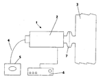
- the gas analysis system 1 is intended to allow the analysis of gaseous effluents contained in a chamber under controlled pressure 3.
- This chamber 3 may be, for example, a vacuum line 3 of equipment semiconductor integrated circuit manufacturing method (not shown).
- the operating principle of the gas analysis system 1 is based on the ionization of the gases and the analysis of the radiative spectrum resulting from the ionization of the gases.
- the gas analysis system 1 comprises a device for ionizing the gases to be analyzed consisting of at least one dedicated plasma source 2, in contact with the gases of the chamber 3, generating a plasma from the gases to analyze.
- This plasma source 2 is powered by a generator adapted to the type of plasma source 2 chosen.
- the plasma source 2 is a radiofrequency plasma source of the ICP type.
- the generator 6 is an RF generator.
- the gas analysis system 1 comprises a device for analyzing ionized gases 4, 5 of optical spectrometer type, having a probe 4 located near the dedicated plasma source 2, analyzing the evolution of a radiative spectrum emitted by the generated plasma.
- the device for analyzing the ionized gases 4, 5 comprises an optical fiber probe 4, one end of which is located near the plasma source 2, inside the chamber analyzed 3, and the other end of which is connected to an optical emission spectrometer 5.
- the radiation emitted by the atoms, molecules, and ions excited by the free electrons of the plasma are transmitted to the optical emission spectrometer 5 via the optical fiber 4.
- the spectrometer Optical emission 5 analyzes the evolutions of these radiations and deduces therefrom information relating to the constituents of the ionized gases.
- system 1 is attached to an enclosure, such as a pipe 3 by an external connection 7.
Landscapes
- Health & Medical Sciences (AREA)
- General Physics & Mathematics (AREA)
- Pathology (AREA)
- Life Sciences & Earth Sciences (AREA)
- Chemical & Material Sciences (AREA)
- Analytical Chemistry (AREA)
- Biochemistry (AREA)
- General Health & Medical Sciences (AREA)
- Nuclear Medicine, Radiotherapy & Molecular Imaging (AREA)
- Physics & Mathematics (AREA)
- Immunology (AREA)
- Other Investigation Or Analysis Of Materials By Electrical Means (AREA)
- Investigating, Analyzing Materials By Fluorescence Or Luminescence (AREA)
- Investigating Or Analysing Materials By Optical Means (AREA)
- Sampling And Sample Adjustment (AREA)
- Chemical Vapour Deposition (AREA)
- Automatic Analysis And Handling Materials Therefor (AREA)
- Organic Low-Molecular-Weight Compounds And Preparation Thereof (AREA)
Description
- L'invention concerne un équipement industriel comprenant au moins une enceinte à pression contrôlée, et un système d'analyse des gaz contenus dans l'enceinte à pression contrôlée.
- Les progrès réalisés, lors de ces dernières années dans l'industrie du semi-conducteur, sont essentiellement liés à l'accroissement de l'intégration de circuits électroniques sur des composants de quelques millimètres carrés ; ceci sur des substrats de silicium de plus en plus grand (diamètre de 200 mm à 300 mm).
- Les étapes technologiques, nécessaires à la réalisation de tels circuits, sont nombreuses (jusqu'à 400).
- Parmi elles, les étapes de traitement sous vide, jouent un rôle essentiel, tant par leurs capacités à produire de façon continue tout au long du procédé de fabrication que par leurs fonctions à respecter les critères géométriques du composant.
- La mise en place d'un système d'analyse de procédé in situ, identifie les défauts dés leurs créations, réduisant le temps de réaction pendant lequel un nombre important de lots peuvent être produit.
- De ce fait une demande importante apparaît pour le suivi et le contrôle in situ et en temps réel des procédés de fabrication de semi-conducteur par plasma, réalisés sous vide.
- Cette demande s'affirme non seulement dans les chambres où sont réalisées les différentes étapes, mais aussi sur les différents composants constituant les lignes de pompage.
- Parmi les étapes d'inspection in situ, l'analyse d'éléments organiques, particules, moisissure, ions métalliques, ainsi que tous gaz sous forme gazeuse ou en limite de condensation est importante car elle permet :
- De déterminer si les conditions optimales de fabrication sont réalisées ; par exemple, une analyse in situ, effectuée dans le système de pompage de vide, en aval de la chambre de procédé permet un meilleur contrôle de l'environnement des plaques de silicium, améliorant de ce fait les rendements de production.
- D'estimer le vieillissement des composants mécaniques constituant la machine et donc, par l'intermédiaire d'une maintenance prédictive, gérer parfaitement le planning de maintenance de la machine en évitant d'aller jusqu'à l'incident.
- Le problème rencontré dans la mise en place d'une technique d'analyse de gaz réside dans le coût d'investissement et le gain réalisé par une détection préventive des défauts en comparaison des coûts de production et de qualité générée par les procédés.
- De plus, le système d'analyse de gaz doit être de plus en plus petit afin de tenir compte de l'intégration des systèmes de pompages et des équipements semi-conducteurs.
- Un analyseur de gaz fonctionnant de 0,1 mbar à 1000 mbar permettrait un suivi des espèces réactives pendant les étapes de procédés ; ceci jusqu'à la sortie de l'équipement sous vide, assurant un meilleur contrôle des gaz relâchés dans l'atmosphère.
- On connaît l'analyse résiduelle de gaz (« RGA ») par spectrométrie de masse permettant de détecter toutes les espèces gazeuses neutres ou chargées. Les molécules sont habituellement ionisées dans une chambre d'ionisation par des électrons issus de l'émission thermoïonique d'un filament chaud. Cette technologie est applicable pour une pression inférieure à 10-6 mbar, au-dessus de 10-5 mbar la réponse devient non linaire et au-dessus de 10-4 mbar le filament peut être détruit.
- Pour une analyse de gaz dans l'intervalle souhaité (0,1 à 1000 mbar), la mise en place d'un pompage différentiel est nécessaire, afin de réduire la pression à l'intérieur de la cellule d'analyse, pour éviter la destruction du filament. Ce dispositif de pompage différentiel comprend plusieurs pompe à vide et de nombreuses vannes.
- Du fait de l'utilisation de plusieurs pompes à vide et de vannes, le coût d'un analyseur de gaz, fonctionnant à haute pression (0,1 à 1000 mbar), est six fois plus élevé qu'un analyseur de type RGA, analysant uniquement le vide résiduel ; rendant son prix dissuasif vis à vis du coût de la machine fabriquant des semi-conducteurs et des rendements quantitatifs et qualitatifs de celle-ci.
- De plus, l'espace occupé par un analyseur de gaz en masse avec pompage différentiel est important, car il intègre plusieurs composants sous vide volumineux. Ceci rend son intégration difficile dans les équipements sous vide actuel, comprenant souvent plusieurs chambres de fabrication.
- C'est pourquoi, peu d'équipements sous vide sont équipés avec un analyseur de gaz, malgré une demande de l'industrie.
- On connaît par ailleurs l'utilisation de la spectroscopie par émission optique sur des équipements de fabrication de semi-conducteurs. La spectrométrie par émission est utilisée pour effectuer la détection de fin d'attaque dans les procédés de gravure des circuits ou composants semi-conducteurs. Le plasma analysé est celui généré par le réacteur de l'équipement, ce dernier est simplement instrumenté par un spectromètre d'émission qui analyse la lumière du procédé de gravure, permettant un contrôle des étapes du procédé lui-même.
- Le but de l'invention, est d'utiliser la spectrométrie par émission optique pour contrôler, non pas les étapes du procédé de fabrication ou de gravure de l'équipement semi-conducteur, mais tous les constituants gazeux de l'environnement sous vide de l'équipement.
- A cet effet, l'invention concerne un équipement comprenant au moins une enceinte (3) à pression contrôlée, et un système d'analyse des gaz contenus dans une enceinte sous pression contrôlée, le système d'analyse de gaz comprenant un dispositif pour ioniser les gaz à analyser, et un dispositif d'analyse des gaz ionisés, qui comprend un capteur de radiation, situé à proximité de la zone de génération du plasma, connecté à un spectromètre optique analysant l'évolution du spectre radiatif, émis par le plasma généré.Un tel équipement est connu par le document
US-A- 5825485 . - Selon l'invention,
le dispositif pour ioniser les gaz à analyser comprend une source de plasma de type ICP générant un plasma à partir des gaz à analyser, combinée avec un générateur radiofréquence.
et le système d'analyse de gaz est rapporté par un raccord extérieur sur l'enceinte dans laquelle les gaz à analyser sont contenus. - La source de plasma est cavité résonante ou de type utilisant le principe de propagation d'une surface d'onde.
- une source plasma Radiofréquence de type ICP. Cette dernière nécessite un diélectrique en quartz ou en alumine (cela dépend de la nature chimique des effluents : les gaz fluorés réagissent fortement avec le quartz) qui assure l'étanchéité et la transparence des ondes électromagnétiques.
- Le capteur de radiation peut être une fibre optique assurant le captage et le transport du spectre radiatif émis par le plasma généré vers le spectromètre optique.
- La sources permet la création d'un plasma à partir des gaz existant dans l'enceinte, ceci en cours de fonctionnement de l'équipement et pour des basses pressions jusqu'à la pression atmosphérique.
- Le rendement d'ionisation obtenue par ces types de source plasma est proche de 10 % pour une pression de 10-1 mbar, d'où une très grande sensibilité dans les mesures.
- Le spectromètre optique, après diffraction de la lumière, analyse en temps réel, les évolutions et radiations émises par les atomes, molécules et ions, excitées par les électrons libres du plasma.
- Ainsi, l'utilisation combinée d'une source de plasma, pouvant fonctionner à la pression atmosphérique et d'un système d'analyse spectrale d'émission optique, permet un diagnostic permanent des gaz se situant à l'intérieur d'une enceinte à pression contrôlée.
- L'utilisation d'un pompage différentiel n'est pas nécessaire au fonctionnement de la source d'ionisation, ceci réduit le volume de l'analyseur de gaz et de ce fait il s'intègre facilement sur l'équipement semi-conducteur (en série ou par l'intermédiaire d'un raccord standard).
- Enfin le coût de cette technique d'analyse optique est faible car elle associe uniquement une source d'ionisation avec un détecteur optique. Cela facilite sa généralisation sur les lignes de vide des équipements utilisés dans l'industrie du semi- conducteur.
- D'autres avantages et caractéristiques de la présente invention résulteront de la description qui va suivre en référence aux dessins annexés dans lesquels :
- La figure unique est une représentation schématique d'un mode de montage d'un système selon la présente invention.
- Le système d'analyse de gaz 1 selon l'invention est destiné à permettre l'analyse d'effluents gazeux contenus dans une enceinte sous pression contrôlée 3. Celle enceinte 3 pourra être, par exemple, une ligne de vide 3 d'un équipement de fabrication de circuits intégrés semi-conducteurs (non représenté).
- Le principe de fonctionnement du système d'analyse des gaz 1 repose sur l'ionisation des gaz et l'analyse du spectre radiatif résultant de l'ionisation des gaz.
- A cet effet, le système d'analyse des gaz 1 comprend un dispositif pour ioniser les gaz à analyser constitué d'au moins une source de plasma dédiée 2, au contact des gaz de l'enceinte 3, générant un plasma à partir des gaz à analyser. Cette source de plasma 2 est alimentée par un générateur adapté 6 au type de source de plasma 2 choisie.
- La source de plasma 2 est une source plasma Radiofréquence de type ICP. Dans ce cas, le générateur 6 est un générateur RF.
- Pour analyser le plasma, le système d'analyse des gaz 1 selon l'invention comprend un dispositif d'analyses des gaz ionisés 4, 5 de type spectromètre optique, ayant une sonde 4 située à proximité de la source de plasma 2 dédiée, analysant l'évolution d'un spectre radiatif, émis par le plasma généré. Le dispositif d'analyse des gaz ionisés 4, 5 comprend une fibre optique sonde 4, dont une extrémité est située à proximité de la source de plasma 2, à l'intérieur de l'enceinte analysée 3, et dont l'autre extrémité est connectée à un spectromètre d'émission optique 5. Les radiations émises par les atomes, molécules, et ions excités par les électrons libres du plasma, sont transmises au spectromètre d'émission optique 5 par l'intermédiaire de la fibre optique 4. Le spectromètre d'émission optique 5 analyse les évolutions de ces radiations et en déduit des informations relatives aux constituants des gaz ionisés.
- Dans un autre mode de montage représenté sur la figure 2, le système 1 selon l'invention est rapporté sur une enceinte, telle qu'une canalisation 3 par un raccord extérieur 7.
- Bien entendu, l'invention n'est pas limitée au mode de réalisation décrit, mais elle est susceptible de nombreuses variantes accessibles à l'homme du métier sans que l'on s'écarte de l'invention.
Claims (1)
- Equipement comprenant au moins une enceinte (3) à pression contrôlée, et un système d'analyse des gaz (1) contenus dans l'enceinte à pression contrôlée, le système d'analyse de gaz (1) comprenant- un dispositif (2, 6) pour ioniser les gaz à analyser; et- un dispositif (4, 5) d'analyse des gaz ionisés comprend un capteur de radiation (4), situé à proximité de la zone d'ionisation, connecté à un spectromètre optique (5) analysant l'évolution du spectre radiatif,caractérisé en ce que le dispositif (2, 6) pour ioniser les gaz à analyser comprend une source de plasma (2) de type ICP pour générer un plasma à partir des gaz à analyser, combinée avec un générateur (6) radiofréquence, et en ce que le système d'analyse (1) est rapporté par un raccord extérieur (7) sur l'enceinte (3) dans laquelle les gaz à analyser sont contenus.
Applications Claiming Priority (2)
| Application Number | Priority Date | Filing Date | Title |
|---|---|---|---|
| FR9900723A FR2788854B1 (fr) | 1999-01-22 | 1999-01-22 | Systeme et procede d'identification d'effluents gazeux, equipement pourvu d'un tel systeme |
| FR9900723 | 1999-01-22 |
Publications (2)
| Publication Number | Publication Date |
|---|---|
| EP1022559A1 EP1022559A1 (fr) | 2000-07-26 |
| EP1022559B1 true EP1022559B1 (fr) | 2007-08-29 |
Family
ID=9541144
Family Applications (1)
| Application Number | Title | Priority Date | Filing Date |
|---|---|---|---|
| EP00400069A Expired - Lifetime EP1022559B1 (fr) | 1999-01-22 | 2000-01-13 | Equipement d'identification d'effluents gazeux |
Country Status (6)
| Country | Link |
|---|---|
| US (1) | US6643014B2 (fr) |
| EP (1) | EP1022559B1 (fr) |
| JP (2) | JP2000214092A (fr) |
| AT (1) | ATE371858T1 (fr) |
| DE (1) | DE60036145T2 (fr) |
| FR (1) | FR2788854B1 (fr) |
Families Citing this family (25)
| Publication number | Priority date | Publication date | Assignee | Title |
|---|---|---|---|---|
| US6791692B2 (en) * | 2000-11-29 | 2004-09-14 | Lightwind Corporation | Method and device utilizing plasma source for real-time gas sampling |
| GB0101835D0 (en) * | 2001-01-24 | 2001-03-07 | Casect Ltd | Analysable package |
| US7123361B1 (en) | 2003-03-05 | 2006-10-17 | Verionix Incorporated | Microplasma emission spectrometer |
| JP5404984B2 (ja) * | 2003-04-24 | 2014-02-05 | 東京エレクトロン株式会社 | プラズマモニタリング方法、プラズマモニタリング装置及びプラズマ処理装置 |
| US7072028B2 (en) * | 2003-07-25 | 2006-07-04 | Lightwind Corporation | Method and apparatus for chemical monitoring |
| FR2865314B1 (fr) * | 2004-01-20 | 2006-04-28 | Cit Alcatel | Station de controle et de purge de mini-environnement |
| US7309842B1 (en) | 2004-03-19 | 2007-12-18 | Verionix Incorporated | Shielded monolithic microplasma source for prevention of continuous thin film formation |
| DE102004061269A1 (de) * | 2004-12-10 | 2006-06-14 | Siemens Ag | Verfahren zum Reinigen eines Werkstückes mit Halogenionen |
| FR2880105B1 (fr) * | 2004-12-23 | 2007-04-20 | Cie Financiere Alcatel Sa | Dispositif et procede de pilotage de l'operation de deshydratation durant un traitement de lyophilisation |
| FR2887072A1 (fr) * | 2005-06-08 | 2006-12-15 | Alcatel Sa | Systeme spectographique ameliore avec source plasma |
| GB2441582A (en) * | 2006-09-01 | 2008-03-12 | Gencoa Ltd | Process monitoring and control |
| US20080090310A1 (en) * | 2006-10-13 | 2008-04-17 | Tokyo Electron Limited | Substrate processing apparatus and substrate processing termination detection method |
| FR2907219B1 (fr) * | 2006-10-17 | 2008-12-12 | Alcatel Sa | Caracterisation de gaz par spectrometrie optique a emission |
| US9997325B2 (en) | 2008-07-17 | 2018-06-12 | Verity Instruments, Inc. | Electron beam exciter for use in chemical analysis in processing systems |
| FR2955927B1 (fr) | 2010-02-01 | 2012-04-06 | Alcatel Lucent | Dispositif et procede de pilotage d'une operation de deshydratation durant un traitement de lyophilisation |
| CN103048377B (zh) * | 2011-10-17 | 2015-06-10 | 中国科学院化学研究所 | 极紫外(euv)光刻胶超高真空热处理检测装置与方法 |
| CA2905931C (fr) | 2013-03-13 | 2021-10-26 | Radom Corporation | Spectrometre a plasma a micro-ondes utilisant un resonateur dielectrique |
| DE102014000343A1 (de) * | 2014-01-11 | 2015-07-16 | Dräger Safety AG & Co. KGaA | Gasmessgerät |
| ES2589964B1 (es) * | 2015-04-17 | 2017-09-05 | Abengoa Solar New Technologies, S.A. | Sistema y método de análisis del gas presente en el espacio interanular de receptores solares de tubo |
| US10337998B2 (en) | 2017-02-17 | 2019-07-02 | Radom Corporation | Plasma generator assembly for mass spectroscopy |
| KR101931324B1 (ko) | 2017-09-14 | 2018-12-20 | (주)나노텍 | 셀프 플라즈마 챔버의 오염 억제 장치 |
| CN111197157A (zh) * | 2018-11-16 | 2020-05-26 | 长鑫存储技术有限公司 | 具有工艺腔室实时监控功能的半导体制造装置 |
| CN109959647B (zh) * | 2019-04-17 | 2021-08-31 | 广东省新材料研究所 | 一种光谱诊断辅助装置 |
| EP4276457A4 (fr) * | 2021-01-29 | 2024-12-04 | Atonarp Inc. | Dispositif d'analyse de gaz et procédé de commande |
| KR102686910B1 (ko) | 2021-08-09 | 2024-07-19 | 삼성전자주식회사 | 반도체 소자의 제조 장치 및 반도체 소자의 제조 방법 |
Citations (2)
| Publication number | Priority date | Publication date | Assignee | Title |
|---|---|---|---|---|
| US5632821A (en) * | 1995-03-03 | 1997-05-27 | Anelva Corporation | Post treatment method for in-situ cleaning |
| WO2000031773A1 (fr) * | 1998-11-19 | 2000-06-02 | Applied Materials, Inc. | Procede et dispositif de detection optique de composition d'effluent |
Family Cites Families (16)
| Publication number | Priority date | Publication date | Assignee | Title |
|---|---|---|---|---|
| US3521959A (en) * | 1967-08-29 | 1970-07-28 | Atomic Energy Commission | Method for direct spectrographic analysis of molten metals |
| US3843257A (en) * | 1971-11-30 | 1974-10-22 | Monsanto Res Corp | Microwave-excited emission detector |
| US3958883A (en) * | 1974-07-10 | 1976-05-25 | Baird-Atomic, Inc. | Radio frequency induced plasma excitation of optical emission spectroscopic samples |
| DE2649912A1 (de) * | 1975-11-28 | 1977-06-08 | Macourt | Trennung und analyse von teilchenueberzuegen |
| US4629887A (en) * | 1983-03-08 | 1986-12-16 | Allied Corporation | Plasma excitation system |
| JPH01129140A (ja) * | 1987-11-16 | 1989-05-22 | Hitachi Ltd | プラズマ発光分光分析装置 |
| JP2675561B2 (ja) * | 1987-12-18 | 1997-11-12 | 株式会社日立製作所 | プラズマ微量元素分折装置 |
| JPH01227048A (ja) * | 1988-03-08 | 1989-09-11 | Fujitsu Ltd | 粒子組成分析装置 |
| US4857136A (en) * | 1988-06-23 | 1989-08-15 | John Zajac | Reactor monitoring system and method |
| JPH0754293B2 (ja) * | 1989-01-09 | 1995-06-07 | 横河電機株式会社 | 微粒子測定装置 |
| JPH0411460U (fr) * | 1990-05-22 | 1992-01-30 | ||
| US5671045A (en) * | 1993-10-22 | 1997-09-23 | Masachusetts Institute Of Technology | Microwave plasma monitoring system for the elemental composition analysis of high temperature process streams |
| DE19505104A1 (de) * | 1995-02-15 | 1996-08-22 | Patent Treuhand Ges Fuer Elektrische Gluehlampen Mbh | Verfahren und Anordnung zur Bestimmung der Reinheit und/oder des Drucks von Gasen für elektrische Lampen |
| US5825485A (en) * | 1995-11-03 | 1998-10-20 | Cohn; Daniel R. | Compact trace element sensor which utilizes microwave generated plasma and which is portable by an individual |
| DE19544506C2 (de) * | 1995-11-29 | 2000-08-10 | Peter R Perzl | Vorrichtung und Verfahren zur Analyse von Flüssigkeitszusammensetzungen mit Hilfe direkter Glimmentladung |
| US5986747A (en) * | 1998-09-24 | 1999-11-16 | Applied Materials, Inc. | Apparatus and method for endpoint detection in non-ionizing gaseous reactor environments |
-
1999
- 1999-01-22 FR FR9900723A patent/FR2788854B1/fr not_active Expired - Fee Related
-
2000
- 2000-01-13 DE DE60036145T patent/DE60036145T2/de not_active Expired - Lifetime
- 2000-01-13 AT AT00400069T patent/ATE371858T1/de not_active IP Right Cessation
- 2000-01-13 EP EP00400069A patent/EP1022559B1/fr not_active Expired - Lifetime
- 2000-01-17 JP JP7613A patent/JP2000214092A/ja active Pending
- 2000-01-19 US US09/487,722 patent/US6643014B2/en not_active Expired - Fee Related
-
2010
- 2010-01-08 JP JP2010002484A patent/JP2010078616A/ja active Pending
Patent Citations (2)
| Publication number | Priority date | Publication date | Assignee | Title |
|---|---|---|---|---|
| US5632821A (en) * | 1995-03-03 | 1997-05-27 | Anelva Corporation | Post treatment method for in-situ cleaning |
| WO2000031773A1 (fr) * | 1998-11-19 | 2000-06-02 | Applied Materials, Inc. | Procede et dispositif de detection optique de composition d'effluent |
Also Published As
| Publication number | Publication date |
|---|---|
| DE60036145D1 (de) | 2007-10-11 |
| US6643014B2 (en) | 2003-11-04 |
| FR2788854B1 (fr) | 2001-05-04 |
| JP2000214092A (ja) | 2000-08-04 |
| ATE371858T1 (de) | 2007-09-15 |
| FR2788854A1 (fr) | 2000-07-28 |
| DE60036145T2 (de) | 2008-05-21 |
| JP2010078616A (ja) | 2010-04-08 |
| US20030160956A1 (en) | 2003-08-28 |
| EP1022559A1 (fr) | 2000-07-26 |
Similar Documents
| Publication | Publication Date | Title |
|---|---|---|
| EP1022559A1 (fr) | Système et procédé d'identification d'effluents gazeux, et équipement pourvu d'un tel système | |
| US6154284A (en) | Chamber effluent monitoring system and semiconductor processing system comprising absorption spectroscopy measurement system, and methods of use | |
| KR101960826B1 (ko) | 플라즈마 처리 장치 및 플라즈마 처리 장치의 운전 방법 | |
| KR100786887B1 (ko) | 챔버로부터의 배출물을 모니터링하는 방법 및 장치와, 챔버 클리닝 장치 | |
| US6366346B1 (en) | Method and apparatus for optical detection of effluent composition | |
| WO2001082019A1 (fr) | Procede et dispositif de conditionnement de l'atmosphere dans une chambre de procedes | |
| KR20050053715A (ko) | 플라즈마 처리 시스템을 구비한 광학 시스템용 장치 및방법 | |
| WO2009146136A1 (fr) | Procédés et appareil pour normaliser des spectres d’émission optiques | |
| US20030046976A1 (en) | Gas analyzing method and gas analyzer for semiconductor treater | |
| EP2195643A1 (fr) | Systeme d'analyse de gaz a basse pression par spectroscopie d'emission optique | |
| US20070215043A1 (en) | Substrate processing apparatus, deposit monitoring apparatus, and deposit monitoring method | |
| US6975393B2 (en) | Method and apparatus for implementing an afterglow emission spectroscopy monitor | |
| US20240063001A1 (en) | Methods and systems for endpoint detection in foreline of chamber clean and foreline clean processes | |
| FR2887072A1 (fr) | Systeme spectographique ameliore avec source plasma | |
| CN1155655A (zh) | 腔废气监测系统、半导体加工系统,以及使用方法 | |
| JP3727620B2 (ja) | 計測用窓部を備えたプラズマ処理装置 | |
| KR20220086488A (ko) | 반도체/디스플레이 플라즈마 화학증착공정 모니터링 전용 실시간 온도편차 보정 발광분광분석시스템 | |
| JP2003163203A (ja) | 半導体製造装置 | |
| WO2002023160A1 (fr) | Moniteur de spectroscopie d'emission a lueur de post-decharge | |
| KR102854480B1 (ko) | 광원을 이용한 oes 플라즈마 모니터링 시스템 및 플라즈마 공정 모니터링 방법 | |
| JPH0837175A (ja) | 汚染測定方法 | |
| KR102001777B1 (ko) | 모니터링 플라즈마 셀을 이용한 공정 모니터링 장치 및 이를 이용한 공정 모니터링 방법 | |
| JP2018088452A (ja) | 真空処理装置及びパーティクル計測方法 | |
| JP2009501277A (ja) | 光学プラズマ分析装置を含んだ、コンテナ上の内部バリヤー層のpecvd蒸着のための装置 | |
| Bluem et al. | EV-140 P, New Emission Spectroscopic Product for Semiconductor Endpoint, Cleaning and Plasma Chambers Control. |
Legal Events
| Date | Code | Title | Description |
|---|---|---|---|
| PUAI | Public reference made under article 153(3) epc to a published international application that has entered the european phase |
Free format text: ORIGINAL CODE: 0009012 |
|
| AK | Designated contracting states |
Kind code of ref document: A1 Designated state(s): AT BE CH CY DE DK ES FI FR GB GR IE IT LI LU MC NL PT SE |
|
| AX | Request for extension of the european patent |
Free format text: AL;LT;LV;MK;RO;SI |
|
| 17P | Request for examination filed |
Effective date: 20010126 |
|
| AKX | Designation fees paid |
Free format text: AT BE CH CY DE DK ES FI FR GB GR IE IT LI LU MC NL PT SE |
|
| 17Q | First examination report despatched |
Effective date: 20060324 |
|
| GRAP | Despatch of communication of intention to grant a patent |
Free format text: ORIGINAL CODE: EPIDOSNIGR1 |
|
| RTI1 | Title (correction) |
Free format text: EQUIPMENT FOR IDENTIFYING GASEOUS EFFLUENTS
 |
|
| RAP1 | Party data changed (applicant data changed or rights of an application transferred) |
Owner name: ALCATEL LUCENT |
|
| RTI1 | Title (correction) |
Free format text: EQUIPMENT FOR IDENTIFYING GASEOUS EFFLUENTS& XA; |
|
| GRAS | Grant fee paid |
Free format text: ORIGINAL CODE: EPIDOSNIGR3 |
|
| GRAA | (expected) grant |
Free format text: ORIGINAL CODE: 0009210 |
|
| AK | Designated contracting states |
Kind code of ref document: B1 Designated state(s): AT BE CH CY DE DK ES FI FR GB GR IE IT LI LU MC NL PT SE |
|
| REG | Reference to a national code |
Ref country code: GB Ref legal event code: FG4D Free format text: NOT ENGLISH |
|
| REG | Reference to a national code |
Ref country code: CH Ref legal event code: EP |
|
| REG | Reference to a national code |
Ref country code: IE Ref legal event code: FG4D Free format text: LANGUAGE OF EP DOCUMENT: FRENCH |
|
| REF | Corresponds to: |
Ref document number: 60036145 Country of ref document: DE Date of ref document: 20071011 Kind code of ref document: P |
|
| REG | Reference to a national code |
Ref country code: CH Ref legal event code: NV Representative=s name: CABINET ROLAND NITHARDT CONSEILS EN PROPRIETE INDU |
|
| GBT | Gb: translation of ep patent filed (gb section 77(6)(a)/1977) |
Effective date: 20071115 |
|
| PG25 | Lapsed in a contracting state [announced via postgrant information from national office to epo] |
Ref country code: FI Free format text: LAPSE BECAUSE OF FAILURE TO SUBMIT A TRANSLATION OF THE DESCRIPTION OR TO PAY THE FEE WITHIN THE PRESCRIBED TIME-LIMIT Effective date: 20070829 Ref country code: ES Free format text: LAPSE BECAUSE OF FAILURE TO SUBMIT A TRANSLATION OF THE DESCRIPTION OR TO PAY THE FEE WITHIN THE PRESCRIBED TIME-LIMIT Effective date: 20071210 Ref country code: NL Free format text: LAPSE BECAUSE OF FAILURE TO SUBMIT A TRANSLATION OF THE DESCRIPTION OR TO PAY THE FEE WITHIN THE PRESCRIBED TIME-LIMIT Effective date: 20070829 |
|
| NLV1 | Nl: lapsed or annulled due to failure to fulfill the requirements of art. 29p and 29m of the patents act | ||
| PG25 | Lapsed in a contracting state [announced via postgrant information from national office to epo] |
Ref country code: AT Free format text: LAPSE BECAUSE OF FAILURE TO SUBMIT A TRANSLATION OF THE DESCRIPTION OR TO PAY THE FEE WITHIN THE PRESCRIBED TIME-LIMIT Effective date: 20070829 |
|
| REG | Reference to a national code |
Ref country code: IE Ref legal event code: FD4D |
|
| PG25 | Lapsed in a contracting state [announced via postgrant information from national office to epo] |
Ref country code: GR Free format text: LAPSE BECAUSE OF FAILURE TO SUBMIT A TRANSLATION OF THE DESCRIPTION OR TO PAY THE FEE WITHIN THE PRESCRIBED TIME-LIMIT Effective date: 20071130 Ref country code: DK Free format text: LAPSE BECAUSE OF FAILURE TO SUBMIT A TRANSLATION OF THE DESCRIPTION OR TO PAY THE FEE WITHIN THE PRESCRIBED TIME-LIMIT Effective date: 20070829 |
|
| PG25 | Lapsed in a contracting state [announced via postgrant information from national office to epo] |
Ref country code: IE Free format text: LAPSE BECAUSE OF FAILURE TO SUBMIT A TRANSLATION OF THE DESCRIPTION OR TO PAY THE FEE WITHIN THE PRESCRIBED TIME-LIMIT Effective date: 20070829 Ref country code: PT Free format text: LAPSE BECAUSE OF FAILURE TO SUBMIT A TRANSLATION OF THE DESCRIPTION OR TO PAY THE FEE WITHIN THE PRESCRIBED TIME-LIMIT Effective date: 20080129 |
|
| PG25 | Lapsed in a contracting state [announced via postgrant information from national office to epo] |
Ref country code: SE Free format text: LAPSE BECAUSE OF FAILURE TO SUBMIT A TRANSLATION OF THE DESCRIPTION OR TO PAY THE FEE WITHIN THE PRESCRIBED TIME-LIMIT Effective date: 20071129 |
|
| PLBE | No opposition filed within time limit |
Free format text: ORIGINAL CODE: 0009261 |
|
| STAA | Information on the status of an ep patent application or granted ep patent |
Free format text: STATUS: NO OPPOSITION FILED WITHIN TIME LIMIT |
|
| BERE | Be: lapsed |
Owner name: ALCATEL LUCENT Effective date: 20080131 |
|
| 26N | No opposition filed |
Effective date: 20080530 |
|
| PG25 | Lapsed in a contracting state [announced via postgrant information from national office to epo] |
Ref country code: MC Free format text: LAPSE BECAUSE OF NON-PAYMENT OF DUE FEES Effective date: 20080131 |
|
| PG25 | Lapsed in a contracting state [announced via postgrant information from national office to epo] |
Ref country code: BE Free format text: LAPSE BECAUSE OF NON-PAYMENT OF DUE FEES Effective date: 20080131 |
|
| PG25 | Lapsed in a contracting state [announced via postgrant information from national office to epo] |
Ref country code: CY Free format text: LAPSE BECAUSE OF FAILURE TO SUBMIT A TRANSLATION OF THE DESCRIPTION OR TO PAY THE FEE WITHIN THE PRESCRIBED TIME-LIMIT Effective date: 20070829 |
|
| PG25 | Lapsed in a contracting state [announced via postgrant information from national office to epo] |
Ref country code: LU Free format text: LAPSE BECAUSE OF NON-PAYMENT OF DUE FEES Effective date: 20080113 |
|
| PGFP | Annual fee paid to national office [announced via postgrant information from national office to epo] |
Ref country code: DE Payment date: 20110121 Year of fee payment: 12 Ref country code: CH Payment date: 20110124 Year of fee payment: 12 Ref country code: IT Payment date: 20110126 Year of fee payment: 12 Ref country code: FR Payment date: 20110202 Year of fee payment: 12 |
|
| PGFP | Annual fee paid to national office [announced via postgrant information from national office to epo] |
Ref country code: GB Payment date: 20110120 Year of fee payment: 12 |
|
| REG | Reference to a national code |
Ref country code: CH Ref legal event code: PCOW Free format text: ALCATEL LUCENT;3, AVENUE OCTAVE GREARD;75007 PARIS (FR) |
|
| REG | Reference to a national code |
Ref country code: CH Ref legal event code: PL |
|
| GBPC | Gb: european patent ceased through non-payment of renewal fee |
Effective date: 20120113 |
|
| REG | Reference to a national code |
Ref country code: FR Ref legal event code: ST Effective date: 20120928 |
|
| PG25 | Lapsed in a contracting state [announced via postgrant information from national office to epo] |
Ref country code: DE Free format text: LAPSE BECAUSE OF NON-PAYMENT OF DUE FEES Effective date: 20120801 Ref country code: CH Free format text: LAPSE BECAUSE OF NON-PAYMENT OF DUE FEES Effective date: 20120131 Ref country code: LI Free format text: LAPSE BECAUSE OF NON-PAYMENT OF DUE FEES Effective date: 20120131 Ref country code: GB Free format text: LAPSE BECAUSE OF NON-PAYMENT OF DUE FEES Effective date: 20120113 |
|
| REG | Reference to a national code |
Ref country code: DE Ref legal event code: R119 Ref document number: 60036145 Country of ref document: DE Effective date: 20120801 |
|
| PG25 | Lapsed in a contracting state [announced via postgrant information from national office to epo] |
Ref country code: IT Free format text: LAPSE BECAUSE OF NON-PAYMENT OF DUE FEES Effective date: 20120113 |
|
| PG25 | Lapsed in a contracting state [announced via postgrant information from national office to epo] |
Ref country code: FR Free format text: LAPSE BECAUSE OF NON-PAYMENT OF DUE FEES Effective date: 20120131 |
|
| REG | Reference to a national code |
Ref country code: FR Ref legal event code: CA Effective date: 20150521 |
|
| REG | Reference to a national code |
Ref country code: FR Ref legal event code: CA Effective date: 20150521 |