EP1022113A2 - Vorschubeinheit für eine Schweissvorrichtung, insbesondere eine Ultraschall-Schweissvorrichtung - Google Patents
Vorschubeinheit für eine Schweissvorrichtung, insbesondere eine Ultraschall-Schweissvorrichtung Download PDFInfo
- Publication number
- EP1022113A2 EP1022113A2 EP00100615A EP00100615A EP1022113A2 EP 1022113 A2 EP1022113 A2 EP 1022113A2 EP 00100615 A EP00100615 A EP 00100615A EP 00100615 A EP00100615 A EP 00100615A EP 1022113 A2 EP1022113 A2 EP 1022113A2
- Authority
- EP
- European Patent Office
- Prior art keywords
- feed unit
- pressure
- working cylinder
- unit according
- valve
- Prior art date
- Legal status (The legal status is an assumption and is not a legal conclusion. Google has not performed a legal analysis and makes no representation as to the accuracy of the status listed.)
- Granted
Links
Images

Classifications
-
- B—PERFORMING OPERATIONS; TRANSPORTING
- B29—WORKING OF PLASTICS; WORKING OF SUBSTANCES IN A PLASTIC STATE IN GENERAL
- B29C—SHAPING OR JOINING OF PLASTICS; SHAPING OF MATERIAL IN A PLASTIC STATE, NOT OTHERWISE PROVIDED FOR; AFTER-TREATMENT OF THE SHAPED PRODUCTS, e.g. REPAIRING
- B29C66/00—General aspects of processes or apparatus for joining preformed parts
- B29C66/80—General aspects of machine operations or constructions and parts thereof
- B29C66/82—Pressure application arrangements, e.g. transmission or actuating mechanisms for joining tools or clamps
- B29C66/824—Actuating mechanisms
- B29C66/8242—Pneumatic or hydraulic drives
-
- B—PERFORMING OPERATIONS; TRANSPORTING
- B29—WORKING OF PLASTICS; WORKING OF SUBSTANCES IN A PLASTIC STATE IN GENERAL
- B29C—SHAPING OR JOINING OF PLASTICS; SHAPING OF MATERIAL IN A PLASTIC STATE, NOT OTHERWISE PROVIDED FOR; AFTER-TREATMENT OF THE SHAPED PRODUCTS, e.g. REPAIRING
- B29C65/00—Joining or sealing of preformed parts, e.g. welding of plastics materials; Apparatus therefor
- B29C65/02—Joining or sealing of preformed parts, e.g. welding of plastics materials; Apparatus therefor by heating, with or without pressure
- B29C65/08—Joining or sealing of preformed parts, e.g. welding of plastics materials; Apparatus therefor by heating, with or without pressure using ultrasonic vibrations
-
- B—PERFORMING OPERATIONS; TRANSPORTING
- B29—WORKING OF PLASTICS; WORKING OF SUBSTANCES IN A PLASTIC STATE IN GENERAL
- B29C—SHAPING OR JOINING OF PLASTICS; SHAPING OF MATERIAL IN A PLASTIC STATE, NOT OTHERWISE PROVIDED FOR; AFTER-TREATMENT OF THE SHAPED PRODUCTS, e.g. REPAIRING
- B29C66/00—General aspects of processes or apparatus for joining preformed parts
- B29C66/80—General aspects of machine operations or constructions and parts thereof
- B29C66/83—General aspects of machine operations or constructions and parts thereof characterised by the movement of the joining or pressing tools
- B29C66/832—Reciprocating joining or pressing tools
- B29C66/8322—Joining or pressing tools reciprocating along one axis
-
- B—PERFORMING OPERATIONS; TRANSPORTING
- B29—WORKING OF PLASTICS; WORKING OF SUBSTANCES IN A PLASTIC STATE IN GENERAL
- B29C—SHAPING OR JOINING OF PLASTICS; SHAPING OF MATERIAL IN A PLASTIC STATE, NOT OTHERWISE PROVIDED FOR; AFTER-TREATMENT OF THE SHAPED PRODUCTS, e.g. REPAIRING
- B29C66/00—General aspects of processes or apparatus for joining preformed parts
- B29C66/90—Measuring or controlling the joining process
- B29C66/92—Measuring or controlling the joining process by measuring or controlling the pressure, the force, the mechanical power or the displacement of the joining tools
- B29C66/924—Measuring or controlling the joining process by measuring or controlling the pressure, the force, the mechanical power or the displacement of the joining tools by controlling or regulating the pressure, the force, the mechanical power or the displacement of the joining tools
- B29C66/9241—Measuring or controlling the joining process by measuring or controlling the pressure, the force, the mechanical power or the displacement of the joining tools by controlling or regulating the pressure, the force, the mechanical power or the displacement of the joining tools by controlling or regulating the pressure, the force or the mechanical power
-
- F—MECHANICAL ENGINEERING; LIGHTING; HEATING; WEAPONS; BLASTING
- F15—FLUID-PRESSURE ACTUATORS; HYDRAULICS OR PNEUMATICS IN GENERAL
- F15B—SYSTEMS ACTING BY MEANS OF FLUIDS IN GENERAL; FLUID-PRESSURE ACTUATORS, e.g. SERVOMOTORS; DETAILS OF FLUID-PRESSURE SYSTEMS, NOT OTHERWISE PROVIDED FOR
- F15B15/00—Fluid-actuated devices for displacing a member from one position to another; Gearing associated therewith
- F15B15/20—Other details, e.g. assembly with regulating devices
- F15B15/202—Externally-operated valves mounted in or on the actuator
-
- F—MECHANICAL ENGINEERING; LIGHTING; HEATING; WEAPONS; BLASTING
- F15—FLUID-PRESSURE ACTUATORS; HYDRAULICS OR PNEUMATICS IN GENERAL
- F15B—SYSTEMS ACTING BY MEANS OF FLUIDS IN GENERAL; FLUID-PRESSURE ACTUATORS, e.g. SERVOMOTORS; DETAILS OF FLUID-PRESSURE SYSTEMS, NOT OTHERWISE PROVIDED FOR
- F15B15/00—Fluid-actuated devices for displacing a member from one position to another; Gearing associated therewith
- F15B15/20—Other details, e.g. assembly with regulating devices
- F15B15/28—Means for indicating the position, e.g. end of stroke
- F15B15/2815—Position sensing, i.e. means for continuous measurement of position, e.g. LVDT
- F15B15/2853—Position sensing, i.e. means for continuous measurement of position, e.g. LVDT using potentiometers
-
- B—PERFORMING OPERATIONS; TRANSPORTING
- B29—WORKING OF PLASTICS; WORKING OF SUBSTANCES IN A PLASTIC STATE IN GENERAL
- B29C—SHAPING OR JOINING OF PLASTICS; SHAPING OF MATERIAL IN A PLASTIC STATE, NOT OTHERWISE PROVIDED FOR; AFTER-TREATMENT OF THE SHAPED PRODUCTS, e.g. REPAIRING
- B29C66/00—General aspects of processes or apparatus for joining preformed parts
- B29C66/70—General aspects of processes or apparatus for joining preformed parts characterised by the composition, physical properties or the structure of the material of the parts to be joined; Joining with non-plastics material
- B29C66/73—General aspects of processes or apparatus for joining preformed parts characterised by the composition, physical properties or the structure of the material of the parts to be joined; Joining with non-plastics material characterised by the intensive physical properties of the material of the parts to be joined, by the optical properties of the material of the parts to be joined, by the extensive physical properties of the parts to be joined, by the state of the material of the parts to be joined or by the material of the parts to be joined being a thermoplastic or a thermoset
- B29C66/739—General aspects of processes or apparatus for joining preformed parts characterised by the composition, physical properties or the structure of the material of the parts to be joined; Joining with non-plastics material characterised by the intensive physical properties of the material of the parts to be joined, by the optical properties of the material of the parts to be joined, by the extensive physical properties of the parts to be joined, by the state of the material of the parts to be joined or by the material of the parts to be joined being a thermoplastic or a thermoset characterised by the material of the parts to be joined being a thermoplastic or a thermoset
- B29C66/7392—General aspects of processes or apparatus for joining preformed parts characterised by the composition, physical properties or the structure of the material of the parts to be joined; Joining with non-plastics material characterised by the intensive physical properties of the material of the parts to be joined, by the optical properties of the material of the parts to be joined, by the extensive physical properties of the parts to be joined, by the state of the material of the parts to be joined or by the material of the parts to be joined being a thermoplastic or a thermoset characterised by the material of the parts to be joined being a thermoplastic or a thermoset characterised by the material of at least one of the parts being a thermoplastic
- B29C66/73921—General aspects of processes or apparatus for joining preformed parts characterised by the composition, physical properties or the structure of the material of the parts to be joined; Joining with non-plastics material characterised by the intensive physical properties of the material of the parts to be joined, by the optical properties of the material of the parts to be joined, by the extensive physical properties of the parts to be joined, by the state of the material of the parts to be joined or by the material of the parts to be joined being a thermoplastic or a thermoset characterised by the material of the parts to be joined being a thermoplastic or a thermoset characterised by the material of at least one of the parts being a thermoplastic characterised by the materials of both parts being thermoplastics
-
- B—PERFORMING OPERATIONS; TRANSPORTING
- B29—WORKING OF PLASTICS; WORKING OF SUBSTANCES IN A PLASTIC STATE IN GENERAL
- B29C—SHAPING OR JOINING OF PLASTICS; SHAPING OF MATERIAL IN A PLASTIC STATE, NOT OTHERWISE PROVIDED FOR; AFTER-TREATMENT OF THE SHAPED PRODUCTS, e.g. REPAIRING
- B29C66/00—General aspects of processes or apparatus for joining preformed parts
- B29C66/90—Measuring or controlling the joining process
- B29C66/92—Measuring or controlling the joining process by measuring or controlling the pressure, the force, the mechanical power or the displacement of the joining tools
- B29C66/922—Measuring or controlling the joining process by measuring or controlling the pressure, the force, the mechanical power or the displacement of the joining tools by measuring the pressure, the force, the mechanical power or the displacement of the joining tools
- B29C66/9221—Measuring or controlling the joining process by measuring or controlling the pressure, the force, the mechanical power or the displacement of the joining tools by measuring the pressure, the force, the mechanical power or the displacement of the joining tools by measuring the pressure, the force or the mechanical power
-
- B—PERFORMING OPERATIONS; TRANSPORTING
- B29—WORKING OF PLASTICS; WORKING OF SUBSTANCES IN A PLASTIC STATE IN GENERAL
- B29C—SHAPING OR JOINING OF PLASTICS; SHAPING OF MATERIAL IN A PLASTIC STATE, NOT OTHERWISE PROVIDED FOR; AFTER-TREATMENT OF THE SHAPED PRODUCTS, e.g. REPAIRING
- B29C66/00—General aspects of processes or apparatus for joining preformed parts
- B29C66/90—Measuring or controlling the joining process
- B29C66/92—Measuring or controlling the joining process by measuring or controlling the pressure, the force, the mechanical power or the displacement of the joining tools
- B29C66/922—Measuring or controlling the joining process by measuring or controlling the pressure, the force, the mechanical power or the displacement of the joining tools by measuring the pressure, the force, the mechanical power or the displacement of the joining tools
- B29C66/9231—Measuring or controlling the joining process by measuring or controlling the pressure, the force, the mechanical power or the displacement of the joining tools by measuring the pressure, the force, the mechanical power or the displacement of the joining tools by measuring the displacement of the joining tools
-
- B—PERFORMING OPERATIONS; TRANSPORTING
- B29—WORKING OF PLASTICS; WORKING OF SUBSTANCES IN A PLASTIC STATE IN GENERAL
- B29C—SHAPING OR JOINING OF PLASTICS; SHAPING OF MATERIAL IN A PLASTIC STATE, NOT OTHERWISE PROVIDED FOR; AFTER-TREATMENT OF THE SHAPED PRODUCTS, e.g. REPAIRING
- B29C66/00—General aspects of processes or apparatus for joining preformed parts
- B29C66/90—Measuring or controlling the joining process
- B29C66/94—Measuring or controlling the joining process by measuring or controlling the time
Definitions
- the invention relates to a feed unit for a welding device, in particular an ultrasonic welding device, with one along a linear guide movable, carrying a welding tool of the welding device Carriage, and with at least one hydraulically connected to the carriage or pneumatically operated, which can be pressurized via controlled valves Working cylinder.
- Ultrasonic welding is widely used to process thermoplastics used.
- a sonotrode of the equipped with a piezoelectric or magnetostrictive electro-mechanical vibration transducer Welding tool of the ultrasonic welding device sets one of one Vibration generator generated high frequency electrical vibration in one mechanical vibration around, which, adapted to the workpiece to be machined, this plasticized immediately before an intended connection or deformation.
- the pressure on the workpiece is reduced by one of Size and shape of the workpiece and the type of plastic used dependent time function controlled, the vibration generator too predetermined times is switched on or off.
- To generate the Welding pressure becomes the welding tool connected to the slide by the force of the working cylinder acting on the slide pressed the workpiece.
- the entire electrical control including the pressure supply controlling valves arranged separately from the feed unit and connected to it via long hose lines. Electrical signals, such as. B. the positions of end position contacts are sent to the controller via cable transfer.
- the invention is therefore based on the object of a feed unit at the beginning to create described type in which the occurrence of adverse Pressure fluctuations are minimized or at least reduced.
- This object is achieved in that for setting the the pressure causing the movement of the working cylinder in the vicinity of the working cylinder arranged valve is provided: its output via a short pressure line is connected to the input of the working cylinder.
- the measures according to the invention have the advantage that those with pressure changes acted upon, by the valve, in particular by the proportional valve, to Working cylinder leading to this pressure line supplying the pressure medium briefly is, so that essentially no disturbing pressure fluctuations arise can.
- the one in the hose line leading to the valve External pressure generating device generated primary pressure affects the working cylinder no longer immediate and is usually during operation largely constant, so that there are no disturbing the welding process Pressure fluctuations arise.
- proportional valve and preferably a pressure sensor and / or the position of the carriage and thus the position sensor of the welding tool in one housing enclosing the working cylinder. So all of these are Protected facilities against external influences and damage and the internal pressure line between working cylinder and proportional valve is very short executed.
- feed unit according to the invention sees a double-acting also called a differential cylinder Working cylinder in front. Compared to one that only acts in the direction of thrust Working cylinder the advantage of being able to carry out the return stroke.
- feed unit according to the invention is the subject of claim 10 and relates to the electrical control, which is preferably designed here as a programmable logic controller and control signals for the movements of many different welding processes contains preprogrammed.
- FIGS. 1a and 1b An exemplary embodiment is shown schematically and in side view in FIGS. 1a and 1b reproduced a feed unit.
- 1 denotes a linear guide, along which a slide 2 slides, which carries a welding tool 10 carries an electrical-mechanical converter in a converter holder 2a 11 with one coupled to it, corresponding to the one to be processed Has workpiece designed sonotrode 12.
- the carriage 2 is preferably with one double-acting, pneumatic or hydraulic working cylinder 3 connected, the piston 3 'either push or pull on the grindings 2 exercises.
- Via pressure feeds 8, 9 which, depending on the pressure transmission medium, e.g. Compressed air or hydraulic fluid are designed accordingly, the piston 3 'in the direction of thrust or - after completion of the welding process - in Return stroke direction pressurized.
- the generally time-dependent setting of the welding pressure takes place at the described feed unit via a proportional valve 4 that immediately above the working cylinder 3 in an extension of the working cylinder 3 enclosing housing 7 and arranged with its pressure output side the thrust-generating cylinder chamber of the working cylinder 3 is connected.
- the proportional valve 4 receives the largely constant inlet pressure the pressure feed 8, which, like the pressure feed 9 required for the return stroke and the electrical leads brought together in a socket 14 is preferably attached to the housing 7 at a protected location.
- the proportional valve 4 is used by an electrical control device, not shown stamped electrical control signal into a corresponding one Outlet pressure for the working cylinder 3 um, but not the inlet pressure can exceed, so that the pressure curve below the inlet pressure during a welding process set by specifying the control signal curve can be. Due to the preferred use of a programmable logic controller Control for specifying the control of the proportional valve 4 Control signals can be saved once optimized welding processes and if necessary be retrieved.
- a welding process runs z. B. from:
- the proportional valve 4 of the feed unit receives, in addition to a constant inlet pressure via the pressure supply 8, a defined control signal is supplied and generates one on the output side this control signal corresponding pressure on the thrust side of the working cylinder 3.
- the piston 3 'of the working cylinder 3 now exerts a force on the slide 2 of the feed unit, under which this is in the direction of a workpiece (not shown) moved until the sonotrode 12 on the workpiece to be welded, e.g. B. sits on a prepared rivet dome.
- the ultrasonic generator switches (not shown) while welding pressure according to one of the control of predetermined pressure-time profile is controlled.
- the rivet dome is plastified via the sonotrode 12 and under the effect of the welding pressure deformed down to a preselected depth.
- the depth reached can be measured by a odometer 6 or, less precise, determined by using empirical values over time will.
- the ultrasound generator is switched off and the welding pressure is increased to a maximum value. This will the rivet dome pressed a short way with high pressure, which is a Solidification of the rivet head causes.
- a predetermined cooling time switches the proportional valve 4 to venting and via an external return valve and the pressure feed 9 becomes pressure on the return stroke side of the working cylinder 3 given and the feed unit with it in the basic position pulled back.
- Figure 1 b shows the feed unit already shown in Figure 1a in one Side view from the direction designated X in FIG. 1a.
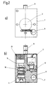
- FIG. 2a shows a top view of the feed unit in the one in FIG. 1a with Y. designated direction again.
- the broken circular line shows the position of the working cylinder 3, which is not visible from the outside. Also the orders to see the encoder 6 and the pressure supply 8.
- FIG. 1 A sectional view shown in Figure 2b along the drawn in Fig. 1 Line A-A shows the position of the proportional valve 4 within the housing 7.
- a pressure sensor 5 can be seen which is connected to the Pressure output side of the proportional valve 4 and one of these to the working cylinder 3 leading pressure line 11 is connected.
- An inlet pressure line 10 leads - not recognizable in the sectional view - to the pressure feed 8.
- From the Pressure outlet side of the proportional valve 4 leads a hole to a service connection 12, which is used for measurement and test purposes.
- One in the axis of the proportional valve 4 arranged muffler 12 weakens the pneumatic Switching noises and needs to be used a hydraulically operated cylinder is not provided become.
- the welding device is an ultrasonic welding device acts.
- the feed unit described in other welding devices in which a feed of the welding tool towards the workpiece is required.
- a heating stamp or a welding tool of a hot air welding device become.
Landscapes
- Engineering & Computer Science (AREA)
- Mechanical Engineering (AREA)
- Physics & Mathematics (AREA)
- Fluid Mechanics (AREA)
- General Engineering & Computer Science (AREA)
- Lining Or Joining Of Plastics Or The Like (AREA)
- Pressure Welding/Diffusion-Bonding (AREA)
- Fluid-Pressure Circuits (AREA)
Abstract
Description
- Figuren 1a und 1b
- Seitenansichten eines Ausführungsbeispiels einer Vorschubeinheit,
- Figur 2 a
- eine Draufsicht auf eine Vorschubeinheit in Vorschubrichtung,
- Figur 2 b
- ein Schnittbild senkrecht zur Vorschubrichtung auf Höhe des Proportionalventils.
Claims (10)
- Vorschubeinheit für eine Schweißvorrichtung, insbesondere eine Ultraschall-Schweißvorrichtung, mit einem entlang einer Linearführung (1) beweglichen, ein Schweißwerkzeug (10) der Schweißvorrichtung tragenden Schlitten (2), und mit mindestens einem mit dem Schlitten verbundenen, hydraulisch oder pneumatisch betätigten, über gesteuerte Ventile mit Druck beaufschlagbaren Arbeitszylinder (3), dadurch gekennzeichnet, daß zur Einstellung des die Bewegung des Arbeitszylinders (3) bewirkenden Druckes ein in der Nähe des Arbeitszylinders (3) angeordnetes Ventil (4) vorgesehen ist, dessen Ausgang über eine kurze Druckleitung (11) mit dem Eingang des Arbeitszylinders (3) verbunden ist.
- Vorschubeinheit nach Anspruch 1, dadurch gekennzeichnet, daß in der Nähe des Arbeitszylinders angeordnete Ventil ein elektrisch gesteuertes Proportionalventil (4) ist.
- Vorschubeinheit nach Anspruch 2, dadurch gekennzeichnet, daß das Proportionalventil (4) in einem den Arbeitszylinder (3) umschließenden Gehäuse (7) angeordnet ist.
- Vorschubeinheit nach einem der vorangehenden Ansprüche, dadurch gekennzeichnet, daß die Vorschubeinheit ein den Ausgangsdruck des Proportionalventils (4) erfassenden Drucksensor aufweist.
- Vorschubeinheit nach einem der vorangehenden Ansprüche, dadurch gekennzeichnet, daß die Vorschubeinheit einen die Position des die Ultraschall-Schweißvorrichtung tragenden Schlittens (2) erfassenden Weggeber (6) aufweist.
- Vorschubeinheit nach einem der vorangehenden Ansprüche, dadurch gekennzeichnet, daß die elektrischen Zuleitungen zum Proportionalventil (4), zum Drucksensor (5) und/oder zum Weggeber (6) über eine gemeinsame Verbindung (14) mit einer von der Vorschubeinheit abgesetzt angeordneten elektrischen Steuerung verbunden sind.
- Vorschubeinheit nach einem der vorangehenden Ansprüche, dadurch gekennzeichnet, daß das Gehäuse (7) Druckzuführungen (8, 9) aufweist, durch welchen der Vorschubeinheit ein einen Kolben (3') des Arbeitszylinders (3) in Schubrichtung oder in Rückhubrichtung druckbeaufschlagendes Druckübertragungsmedium zuführbar ist.
- Vorschubeinheit nach Anspruch 7, dadurch gekennzeichnet, daß die Druckzuführungen (8, 9) als Steckverbindungen ausgeführt sind.
- Vorschubeinheit nach einem der vorstehenden Ansprüche, dadurch gekennzeichnet, daß der Arbeitszylinder (3) ein doppeltwirkender Arbeitszylinder ist, dessen Kolben (3') in Vorschubrichtung vom Ausgangsdruck des Ventils (4) und in Rückhubrichtung durch einen über ein Rückhubventil zugeführten Arbeitsdruck beaufschlagbar ist.
- Vorschubeinheit nach einem der vorangehenden Ansprüche, dadurch gekennzeichnet, daß die Vorschubeinheit mit einer Steuerung verbindbar ist, durch die Steuersignale durch das Proportionalventil (4) und/oder das Rückhubventil erzeugbar sind.
Applications Claiming Priority (2)
| Application Number | Priority Date | Filing Date | Title |
|---|---|---|---|
| DE19902691A DE19902691C1 (de) | 1999-01-23 | 1999-01-23 | Vorschubeinheit für eine Ultraschall-Schweißvorrichtung |
| DE19902691 | 1999-01-23 |
Publications (3)
| Publication Number | Publication Date |
|---|---|
| EP1022113A2 true EP1022113A2 (de) | 2000-07-26 |
| EP1022113A3 EP1022113A3 (de) | 2001-09-12 |
| EP1022113B1 EP1022113B1 (de) | 2003-03-19 |
Family
ID=7895220
Family Applications (1)
| Application Number | Title | Priority Date | Filing Date |
|---|---|---|---|
| EP00100615A Expired - Lifetime EP1022113B1 (de) | 1999-01-23 | 2000-01-13 | Vorschubeinheit für eine Schweissvorrichtung, insbesondere eine Ultraschall-Schweissvorrichtung |
Country Status (4)
| Country | Link |
|---|---|
| EP (1) | EP1022113B1 (de) |
| AT (1) | ATE234722T1 (de) |
| DE (2) | DE19902691C1 (de) |
| ES (1) | ES2194631T3 (de) |
Cited By (5)
| Publication number | Priority date | Publication date | Assignee | Title |
|---|---|---|---|---|
| WO2002046623A1 (es) * | 2000-12-05 | 2002-06-13 | Vitro Corporativo, S.A. De C.V. | Sistema de administracion de un fluido para la operación de un conjunto de cilindro y piston |
| WO2006018415A3 (de) * | 2004-08-14 | 2006-07-06 | Telsonic Holding Ag | Sonotroden-vorschubeinheit für die ultraschall-werkstück-bearbeitung und verfahren zum betreiben einer sonotroden-vorschubeinheit |
| EP2732955A1 (de) | 2012-11-15 | 2014-05-21 | Seat, S.A. | Verfahren zur Herstellung eines Stützanordnung aus Kunststoffmaterial und einer transparenten Bildschirm aus Kunststoffmaterial und eine durch das Verfahren erhaltene Baugruppe |
| CN104259648A (zh) * | 2014-09-06 | 2015-01-07 | 芜湖新宝超声波设备有限公司 | 一种快速加油的超声波焊接单元 |
| CN108340585A (zh) * | 2018-04-29 | 2018-07-31 | 芜湖新宝超声波设备有限公司 | 汽车内饰板超声波焊接流水线的胎膜结构 |
Families Citing this family (1)
| Publication number | Priority date | Publication date | Assignee | Title |
|---|---|---|---|---|
| DE202009005892U1 (de) | 2009-04-22 | 2010-09-16 | Kuka Systems Gmbh | Bearbeitungskopf |
Family Cites Families (2)
| Publication number | Priority date | Publication date | Assignee | Title |
|---|---|---|---|---|
| US2815535A (en) * | 1953-06-26 | 1957-12-10 | Jr Albert G Bodine | Sonic method for powdered metal molding |
| US4735753A (en) * | 1986-07-28 | 1988-04-05 | Ackermann Walter T | Method of making a fastener |
-
1999
- 1999-01-23 DE DE19902691A patent/DE19902691C1/de not_active Expired - Fee Related
-
2000
- 2000-01-13 DE DE50001472T patent/DE50001472D1/de not_active Expired - Lifetime
- 2000-01-13 EP EP00100615A patent/EP1022113B1/de not_active Expired - Lifetime
- 2000-01-13 ES ES00100615T patent/ES2194631T3/es not_active Expired - Lifetime
- 2000-01-13 AT AT00100615T patent/ATE234722T1/de not_active IP Right Cessation
Cited By (8)
| Publication number | Priority date | Publication date | Assignee | Title |
|---|---|---|---|---|
| WO2002046623A1 (es) * | 2000-12-05 | 2002-06-13 | Vitro Corporativo, S.A. De C.V. | Sistema de administracion de un fluido para la operación de un conjunto de cilindro y piston |
| AU2002222773B2 (en) * | 2000-12-05 | 2006-09-14 | Vitro Global, S.A. | Fluid administration system for the operation of a cylinder-piston assembly |
| CN1478179B (zh) * | 2000-12-05 | 2010-11-24 | 维特罗全球有限公司 | 用于控制缸和活塞组件的流体管理系统 |
| WO2006018415A3 (de) * | 2004-08-14 | 2006-07-06 | Telsonic Holding Ag | Sonotroden-vorschubeinheit für die ultraschall-werkstück-bearbeitung und verfahren zum betreiben einer sonotroden-vorschubeinheit |
| EP2732955A1 (de) | 2012-11-15 | 2014-05-21 | Seat, S.A. | Verfahren zur Herstellung eines Stützanordnung aus Kunststoffmaterial und einer transparenten Bildschirm aus Kunststoffmaterial und eine durch das Verfahren erhaltene Baugruppe |
| CN104259648A (zh) * | 2014-09-06 | 2015-01-07 | 芜湖新宝超声波设备有限公司 | 一种快速加油的超声波焊接单元 |
| CN104259648B (zh) * | 2014-09-06 | 2016-05-04 | 芜湖新宝超声波设备有限公司 | 一种快速加油的超声波焊接单元 |
| CN108340585A (zh) * | 2018-04-29 | 2018-07-31 | 芜湖新宝超声波设备有限公司 | 汽车内饰板超声波焊接流水线的胎膜结构 |
Also Published As
| Publication number | Publication date |
|---|---|
| EP1022113B1 (de) | 2003-03-19 |
| ATE234722T1 (de) | 2003-04-15 |
| DE50001472D1 (de) | 2003-04-24 |
| DE19902691C1 (de) | 2000-10-26 |
| ES2194631T3 (es) | 2003-12-01 |
| EP1022113A3 (de) | 2001-09-12 |
Similar Documents
| Publication | Publication Date | Title |
|---|---|---|
| DE69129026T2 (de) | Verfahren und gerät zur verschlussregelung eines formapparates | |
| EP0575343B1 (de) | Vorrichtung zur durchführung einer zweistufigen linearen bewegung | |
| DE69201769T2 (de) | Hydraulische Polsteranordnung für eine Presse, mit einem Absperrventil zum Abschalten der Energieversorgung der Druckbolzen beim Kontakt des beweglichen Werkzeugs mit dem Werkstück. | |
| DE3313249A1 (de) | Hochdruckwasserstrahl-anlage | |
| DE69002143T2 (de) | Stanzmaschine. | |
| DE68914837T2 (de) | Düsenberührungsanordnung für eine einspritzgiessmaschine. | |
| DE3307596C2 (de) | Vorrichtung zur Steuerung der Drehzahl eines Dieselmotors eines Hydraulikbaggers oder dergleichen | |
| DE112016005625T5 (de) | Vorrichtung zum Spritzgießen von Kunststoffmaterialien | |
| EP3727830B1 (de) | Vorrichtung und verfahren zur überwachung eines keiltriebwerkzeuges | |
| EP1022113B1 (de) | Vorschubeinheit für eine Schweissvorrichtung, insbesondere eine Ultraschall-Schweissvorrichtung | |
| EP1388404B1 (de) | Hydraulikaggregat für eine Spritzgiessmaschine | |
| EP2260210A1 (de) | Steuergerät sowie dessen verwendung | |
| DE112016000491T5 (de) | Formwerkzeug, formwerkzeugsystem, und formpressverfahren | |
| WO2018015370A1 (de) | Verfahren und vorrichtung zum abscheren von stangenmaterial | |
| WO1999054092A1 (de) | Druckmittelzange | |
| DE10217585B4 (de) | Einrichtung zum Spritzgießen von Kunststoffen | |
| DE4400350A1 (de) | Bolzenschweißvorrichtung | |
| DE29901140U1 (de) | Vorschubeinheit für eine Ultraschall-Schweißvorrichtung | |
| DE10329898B4 (de) | Verfahren und Vorrichtung zum Umformen von Blechplatinen | |
| DE3336258A1 (de) | Spritzgiess- oder presswerkzeug zur verarbeitung von kunststoffmassen | |
| DE102006055330A1 (de) | Verfahren zur Ablaufprogrammierung eines Spritzgießzyklus einer Spritzgiessmaschine | |
| EP3477121B1 (de) | Druckbegrenzungseinheit für einen druckübersetzer sowie ein druckübersetzer zum antrieb von hydraulikwerkzeugen | |
| EP1413386A1 (de) | Einpressvorrichtung mit hämmernder Schlagvorrichtung | |
| EP0171609A2 (de) | Einrichtung zur Steuerung und/oder Begrenzung der Formauftriebskraft an Spritzgiessmaschinen | |
| DE2621726C2 (de) | Schnittschlagdämpfungseinrichtung an Pressen |
Legal Events
| Date | Code | Title | Description |
|---|---|---|---|
| PUAI | Public reference made under article 153(3) epc to a published international application that has entered the european phase |
Free format text: ORIGINAL CODE: 0009012 |
|
| AK | Designated contracting states |
Kind code of ref document: A2 Designated state(s): AT BE CH CY DE DK ES FI FR GB GR IE IT LI LU MC NL PT SE |
|
| AX | Request for extension of the european patent |
Free format text: AL;LT;LV;MK;RO;SI |
|
| PUAL | Search report despatched |
Free format text: ORIGINAL CODE: 0009013 |
|
| AK | Designated contracting states |
Kind code of ref document: A3 Designated state(s): AT BE CH CY DE DK ES FI FR GB GR IE IT LI LU MC NL PT SE |
|
| AX | Request for extension of the european patent |
Free format text: AL;LT;LV;MK;RO;SI |
|
| RIC1 | Information provided on ipc code assigned before grant |
Free format text: 7B 29C 65/08 A, 7B 29C 65/00 B, 7B 23K 20/10 B |
|
| 17P | Request for examination filed |
Effective date: 20020207 |
|
| AKX | Designation fees paid |
Free format text: AT BE CH CY DE DK ES FI FR GB GR IE IT LI LU MC NL PT SE |
|
| 17Q | First examination report despatched |
Effective date: 20020514 |
|
| GRAH | Despatch of communication of intention to grant a patent |
Free format text: ORIGINAL CODE: EPIDOS IGRA |
|
| GRAH | Despatch of communication of intention to grant a patent |
Free format text: ORIGINAL CODE: EPIDOS IGRA |
|
| GRAA | (expected) grant |
Free format text: ORIGINAL CODE: 0009210 |
|
| AK | Designated contracting states |
Designated state(s): AT BE CH CY DE DK ES FI FR GB GR IE IT LI LU MC NL PT SE |
|
| PG25 | Lapsed in a contracting state [announced via postgrant information from national office to epo] |
Ref country code: GR Free format text: LAPSE BECAUSE OF FAILURE TO SUBMIT A TRANSLATION OF THE DESCRIPTION OR TO PAY THE FEE WITHIN THE PRESCRIBED TIME-LIMIT Effective date: 20030319 Ref country code: NL Free format text: LAPSE BECAUSE OF FAILURE TO SUBMIT A TRANSLATION OF THE DESCRIPTION OR TO PAY THE FEE WITHIN THE PRESCRIBED TIME-LIMIT Effective date: 20030319 Ref country code: IE Free format text: LAPSE BECAUSE OF FAILURE TO SUBMIT A TRANSLATION OF THE DESCRIPTION OR TO PAY THE FEE WITHIN THE PRESCRIBED TIME-LIMIT Effective date: 20030319 Ref country code: FI Free format text: LAPSE BECAUSE OF FAILURE TO SUBMIT A TRANSLATION OF THE DESCRIPTION OR TO PAY THE FEE WITHIN THE PRESCRIBED TIME-LIMIT Effective date: 20030319 Ref country code: CY Free format text: LAPSE BECAUSE OF FAILURE TO SUBMIT A TRANSLATION OF THE DESCRIPTION OR TO PAY THE FEE WITHIN THE PRESCRIBED TIME-LIMIT Effective date: 20030319 |
|
| REG | Reference to a national code |
Ref country code: GB Ref legal event code: FG4D Free format text: NOT ENGLISH |
|
| REG | Reference to a national code |
Ref country code: CH Ref legal event code: EP |
|
| REG | Reference to a national code |
Ref country code: IE Ref legal event code: FG4D Free format text: GERMAN |
|
| REF | Corresponds to: |
Ref document number: 50001472 Country of ref document: DE Date of ref document: 20030424 Kind code of ref document: P |
|
| PG25 | Lapsed in a contracting state [announced via postgrant information from national office to epo] |
Ref country code: DK Free format text: LAPSE BECAUSE OF FAILURE TO SUBMIT A TRANSLATION OF THE DESCRIPTION OR TO PAY THE FEE WITHIN THE PRESCRIBED TIME-LIMIT Effective date: 20030619 Ref country code: SE Free format text: LAPSE BECAUSE OF FAILURE TO SUBMIT A TRANSLATION OF THE DESCRIPTION OR TO PAY THE FEE WITHIN THE PRESCRIBED TIME-LIMIT Effective date: 20030619 |
|
| PG25 | Lapsed in a contracting state [announced via postgrant information from national office to epo] |
Ref country code: PT Free format text: LAPSE BECAUSE OF FAILURE TO SUBMIT A TRANSLATION OF THE DESCRIPTION OR TO PAY THE FEE WITHIN THE PRESCRIBED TIME-LIMIT Effective date: 20030620 |
|
| GBT | Gb: translation of ep patent filed (gb section 77(6)(a)/1977) | ||
| NLV1 | Nl: lapsed or annulled due to failure to fulfill the requirements of art. 29p and 29m of the patents act | ||
| REG | Reference to a national code |
Ref country code: IE Ref legal event code: FD4D Ref document number: 1022113E Country of ref document: IE |
|
| ET | Fr: translation filed | ||
| PG25 | Lapsed in a contracting state [announced via postgrant information from national office to epo] |
Ref country code: LU Free format text: LAPSE BECAUSE OF NON-PAYMENT OF DUE FEES Effective date: 20040113 Ref country code: AT Free format text: LAPSE BECAUSE OF NON-PAYMENT OF DUE FEES Effective date: 20040113 |
|
| PLBE | No opposition filed within time limit |
Free format text: ORIGINAL CODE: 0009261 |
|
| STAA | Information on the status of an ep patent application or granted ep patent |
Free format text: STATUS: NO OPPOSITION FILED WITHIN TIME LIMIT |
|
| PG25 | Lapsed in a contracting state [announced via postgrant information from national office to epo] |
Ref country code: MC Free format text: LAPSE BECAUSE OF NON-PAYMENT OF DUE FEES Effective date: 20040131 Ref country code: LI Free format text: LAPSE BECAUSE OF NON-PAYMENT OF DUE FEES Effective date: 20040131 Ref country code: CH Free format text: LAPSE BECAUSE OF NON-PAYMENT OF DUE FEES Effective date: 20040131 Ref country code: BE Free format text: LAPSE BECAUSE OF NON-PAYMENT OF DUE FEES Effective date: 20040131 |
|
| 26N | No opposition filed |
Effective date: 20031222 |
|
| BERE | Be: lapsed |
Owner name: *SONOTRONIC NAGEL G.M.B.H. Effective date: 20040131 |
|
| REG | Reference to a national code |
Ref country code: CH Ref legal event code: PL |
|
| REG | Reference to a national code |
Ref country code: DE Ref legal event code: R082 Ref document number: 50001472 Country of ref document: DE Representative=s name: HANSMANN & VOGESER, DE Ref country code: DE Ref legal event code: R082 Ref document number: 50001472 Country of ref document: DE Representative=s name: WEICKMANN & WEICKMANN, DE Ref country code: DE Ref legal event code: R082 Ref document number: 50001472 Country of ref document: DE Representative=s name: PATENTANWAELTE WEICKMANN & WEICKMANN, DE Ref country code: DE Ref legal event code: R082 Ref document number: 50001472 Country of ref document: DE Representative=s name: WEICKMANN & WEICKMANN PATENTANWAELTE - RECHTSA, DE Ref country code: DE Ref legal event code: R082 Ref document number: 50001472 Country of ref document: DE Representative=s name: WEICKMANN & WEICKMANN PATENT- UND RECHTSANWAEL, DE |
|
| REG | Reference to a national code |
Ref country code: FR Ref legal event code: PLFP Year of fee payment: 16 |
|
| PGFP | Annual fee paid to national office [announced via postgrant information from national office to epo] |
Ref country code: IT Payment date: 20150126 Year of fee payment: 16 Ref country code: ES Payment date: 20150122 Year of fee payment: 16 |
|
| REG | Reference to a national code |
Ref country code: DE Ref legal event code: R082 Ref document number: 50001472 Country of ref document: DE Representative=s name: PATENTANWAELTE WEICKMANN & WEICKMANN, DE Ref country code: DE Ref legal event code: R082 Ref document number: 50001472 Country of ref document: DE Representative=s name: WEICKMANN & WEICKMANN PATENTANWAELTE - RECHTSA, DE Ref country code: DE Ref legal event code: R082 Ref document number: 50001472 Country of ref document: DE Representative=s name: WEICKMANN & WEICKMANN PATENT- UND RECHTSANWAEL, DE |
|
| PGFP | Annual fee paid to national office [announced via postgrant information from national office to epo] |
Ref country code: FR Payment date: 20150115 Year of fee payment: 16 Ref country code: GB Payment date: 20150123 Year of fee payment: 16 |
|
| GBPC | Gb: european patent ceased through non-payment of renewal fee |
Effective date: 20160113 |
|
| REG | Reference to a national code |
Ref country code: FR Ref legal event code: ST Effective date: 20160930 |
|
| PG25 | Lapsed in a contracting state [announced via postgrant information from national office to epo] |
Ref country code: GB Free format text: LAPSE BECAUSE OF NON-PAYMENT OF DUE FEES Effective date: 20160113 |
|
| PG25 | Lapsed in a contracting state [announced via postgrant information from national office to epo] |
Ref country code: FR Free format text: LAPSE BECAUSE OF NON-PAYMENT OF DUE FEES Effective date: 20160201 |
|
| PG25 | Lapsed in a contracting state [announced via postgrant information from national office to epo] |
Ref country code: IT Free format text: LAPSE BECAUSE OF NON-PAYMENT OF DUE FEES Effective date: 20160113 |
|
| REG | Reference to a national code |
Ref country code: ES Ref legal event code: FD2A Effective date: 20170306 |
|
| PG25 | Lapsed in a contracting state [announced via postgrant information from national office to epo] |
Ref country code: ES Free format text: LAPSE BECAUSE OF NON-PAYMENT OF DUE FEES Effective date: 20160114 |
|
| PGFP | Annual fee paid to national office [announced via postgrant information from national office to epo] |
Ref country code: DE Payment date: 20180129 Year of fee payment: 19 |
|
| REG | Reference to a national code |
Ref country code: DE Ref legal event code: R119 Ref document number: 50001472 Country of ref document: DE |
|
| PG25 | Lapsed in a contracting state [announced via postgrant information from national office to epo] |
Ref country code: DE Free format text: LAPSE BECAUSE OF NON-PAYMENT OF DUE FEES Effective date: 20190801 |