EP1022045A2 - Druckwechseladsorptionsverfahren mit vielstufigem Druckausgleich - Google Patents
Druckwechseladsorptionsverfahren mit vielstufigem Druckausgleich Download PDFInfo
- Publication number
- EP1022045A2 EP1022045A2 EP00300292A EP00300292A EP1022045A2 EP 1022045 A2 EP1022045 A2 EP 1022045A2 EP 00300292 A EP00300292 A EP 00300292A EP 00300292 A EP00300292 A EP 00300292A EP 1022045 A2 EP1022045 A2 EP 1022045A2
- Authority
- EP
- European Patent Office
- Prior art keywords
- adsorption zone
- adsorption
- component
- equalization
- cocurrently
- Prior art date
- Legal status (The legal status is an assumption and is not a legal conclusion. Google has not performed a legal analysis and makes no representation as to the accuracy of the status listed.)
- Withdrawn
Links
- 238000001179 sorption measurement Methods 0.000 claims abstract description 168
- 238000010926 purge Methods 0.000 claims abstract description 69
- 239000000203 mixture Substances 0.000 claims abstract description 34
- 238000000034 method Methods 0.000 claims description 152
- 230000008569 process Effects 0.000 claims description 143
- 239000007789 gas Substances 0.000 claims description 118
- 239000003463 adsorbent Substances 0.000 claims description 34
- UGFAIRIUMAVXCW-UHFFFAOYSA-N Carbon monoxide Chemical group [O+]#[C-] UGFAIRIUMAVXCW-UHFFFAOYSA-N 0.000 claims description 9
- 229910002091 carbon monoxide Inorganic materials 0.000 claims description 9
- IJGRMHOSHXDMSA-UHFFFAOYSA-N Atomic nitrogen Chemical compound N#N IJGRMHOSHXDMSA-UHFFFAOYSA-N 0.000 claims description 8
- CURLTUGMZLYLDI-UHFFFAOYSA-N Carbon dioxide Chemical compound O=C=O CURLTUGMZLYLDI-UHFFFAOYSA-N 0.000 claims description 8
- 229910052739 hydrogen Inorganic materials 0.000 claims description 5
- 239000001257 hydrogen Substances 0.000 claims description 5
- 239000001569 carbon dioxide Substances 0.000 claims description 4
- 229910002092 carbon dioxide Inorganic materials 0.000 claims description 4
- 229910052757 nitrogen Inorganic materials 0.000 claims description 4
- 125000004435 hydrogen atom Chemical class [H]* 0.000 claims 1
- 238000004519 manufacturing process Methods 0.000 abstract description 4
- 230000008929 regeneration Effects 0.000 description 10
- 238000011069 regeneration method Methods 0.000 description 10
- 230000004048 modification Effects 0.000 description 7
- 238000012986 modification Methods 0.000 description 7
- 230000008901 benefit Effects 0.000 description 4
- VNWKTOKETHGBQD-UHFFFAOYSA-N methane Chemical compound C VNWKTOKETHGBQD-UHFFFAOYSA-N 0.000 description 4
- OKTJSMMVPCPJKN-UHFFFAOYSA-N Carbon Chemical compound [C] OKTJSMMVPCPJKN-UHFFFAOYSA-N 0.000 description 3
- RYGMFSIKBFXOCR-UHFFFAOYSA-N Copper Chemical compound [Cu] RYGMFSIKBFXOCR-UHFFFAOYSA-N 0.000 description 3
- 229910052802 copper Inorganic materials 0.000 description 3
- 239000010949 copper Substances 0.000 description 3
- 230000002708 enhancing effect Effects 0.000 description 3
- 150000002431 hydrogen Chemical class 0.000 description 3
- 230000006872 improvement Effects 0.000 description 3
- 238000011084 recovery Methods 0.000 description 3
- 238000003860 storage Methods 0.000 description 3
- 239000010457 zeolite Substances 0.000 description 3
- KDLHZDBZIXYQEI-UHFFFAOYSA-N Palladium Chemical compound [Pd] KDLHZDBZIXYQEI-UHFFFAOYSA-N 0.000 description 2
- PNEYBMLMFCGWSK-UHFFFAOYSA-N aluminium oxide Inorganic materials [O-2].[O-2].[O-2].[Al+3].[Al+3] PNEYBMLMFCGWSK-UHFFFAOYSA-N 0.000 description 2
- 239000012535 impurity Substances 0.000 description 2
- 229910052698 phosphorus Inorganic materials 0.000 description 2
- 238000000926 separation method Methods 0.000 description 2
- 229910052709 silver Inorganic materials 0.000 description 2
- 239000004332 silver Substances 0.000 description 2
- 239000011800 void material Substances 0.000 description 2
- WSWCOQWTEOXDQX-MQQKCMAXSA-M (E,E)-sorbate Chemical compound C\C=C\C=C\C([O-])=O WSWCOQWTEOXDQX-MQQKCMAXSA-M 0.000 description 1
- 239000004215 Carbon black (E152) Substances 0.000 description 1
- VMQMZMRVKUZKQL-UHFFFAOYSA-N Cu+ Chemical compound [Cu+] VMQMZMRVKUZKQL-UHFFFAOYSA-N 0.000 description 1
- JPVYNHNXODAKFH-UHFFFAOYSA-N Cu2+ Chemical compound [Cu+2] JPVYNHNXODAKFH-UHFFFAOYSA-N 0.000 description 1
- UFHFLCQGNIYNRP-UHFFFAOYSA-N Hydrogen Chemical compound [H][H] UFHFLCQGNIYNRP-UHFFFAOYSA-N 0.000 description 1
- VYPSYNLAJGMNEJ-UHFFFAOYSA-N Silicium dioxide Chemical compound O=[Si]=O VYPSYNLAJGMNEJ-UHFFFAOYSA-N 0.000 description 1
- FOIXSVOLVBLSDH-UHFFFAOYSA-N Silver ion Chemical compound [Ag+] FOIXSVOLVBLSDH-UHFFFAOYSA-N 0.000 description 1
- JYIBXUUINYLWLR-UHFFFAOYSA-N aluminum;calcium;potassium;silicon;sodium;trihydrate Chemical compound O.O.O.[Na].[Al].[Si].[K].[Ca] JYIBXUUINYLWLR-UHFFFAOYSA-N 0.000 description 1
- UNYSKUBLZGJSLV-UHFFFAOYSA-L calcium;1,3,5,2,4,6$l^{2}-trioxadisilaluminane 2,4-dioxide;dihydroxide;hexahydrate Chemical compound O.O.O.O.O.O.[OH-].[OH-].[Ca+2].O=[Si]1O[Al]O[Si](=O)O1.O=[Si]1O[Al]O[Si](=O)O1 UNYSKUBLZGJSLV-UHFFFAOYSA-L 0.000 description 1
- 229910052799 carbon Inorganic materials 0.000 description 1
- 229910052676 chabazite Inorganic materials 0.000 description 1
- 229910001603 clinoptilolite Inorganic materials 0.000 description 1
- 229910001431 copper ion Inorganic materials 0.000 description 1
- 230000007423 decrease Effects 0.000 description 1
- 238000003795 desorption Methods 0.000 description 1
- HNPSIPDUKPIQMN-UHFFFAOYSA-N dioxosilane;oxo(oxoalumanyloxy)alumane Chemical class O=[Si]=O.O=[Al]O[Al]=O HNPSIPDUKPIQMN-UHFFFAOYSA-N 0.000 description 1
- 230000000694 effects Effects 0.000 description 1
- 239000012013 faujasite Substances 0.000 description 1
- 238000011010 flushing procedure Methods 0.000 description 1
- 229930195733 hydrocarbon Natural products 0.000 description 1
- 150000002430 hydrocarbons Chemical class 0.000 description 1
- 239000002808 molecular sieve Substances 0.000 description 1
- 229910052680 mordenite Inorganic materials 0.000 description 1
- 229910052763 palladium Inorganic materials 0.000 description 1
- 239000011236 particulate material Substances 0.000 description 1
- 238000000746 purification Methods 0.000 description 1
- 238000002407 reforming Methods 0.000 description 1
- 239000000741 silica gel Substances 0.000 description 1
- 229910002027 silica gel Inorganic materials 0.000 description 1
- 150000003378 silver Chemical class 0.000 description 1
- URGAHOPLAPQHLN-UHFFFAOYSA-N sodium aluminosilicate Chemical compound [Na+].[Al+3].[O-][Si]([O-])=O.[O-][Si]([O-])=O URGAHOPLAPQHLN-UHFFFAOYSA-N 0.000 description 1
- 229940075554 sorbate Drugs 0.000 description 1
- -1 types A Chemical class 0.000 description 1
Images



Classifications
-
- B—PERFORMING OPERATIONS; TRANSPORTING
- B01—PHYSICAL OR CHEMICAL PROCESSES OR APPARATUS IN GENERAL
- B01D—SEPARATION
- B01D53/00—Separation of gases or vapours; Recovering vapours of volatile solvents from gases; Chemical or biological purification of waste gases, e.g. engine exhaust gases, smoke, fumes, flue gases, aerosols
- B01D53/02—Separation of gases or vapours; Recovering vapours of volatile solvents from gases; Chemical or biological purification of waste gases, e.g. engine exhaust gases, smoke, fumes, flue gases, aerosols by adsorption, e.g. preparative gas chromatography
- B01D53/04—Separation of gases or vapours; Recovering vapours of volatile solvents from gases; Chemical or biological purification of waste gases, e.g. engine exhaust gases, smoke, fumes, flue gases, aerosols by adsorption, e.g. preparative gas chromatography with stationary adsorbents
- B01D53/047—Pressure swing adsorption
-
- B—PERFORMING OPERATIONS; TRANSPORTING
- B01—PHYSICAL OR CHEMICAL PROCESSES OR APPARATUS IN GENERAL
- B01D—SEPARATION
- B01D2256/00—Main component in the product gas stream after treatment
- B01D2256/10—Nitrogen
-
- B—PERFORMING OPERATIONS; TRANSPORTING
- B01—PHYSICAL OR CHEMICAL PROCESSES OR APPARATUS IN GENERAL
- B01D—SEPARATION
- B01D2256/00—Main component in the product gas stream after treatment
- B01D2256/16—Hydrogen
-
- B—PERFORMING OPERATIONS; TRANSPORTING
- B01—PHYSICAL OR CHEMICAL PROCESSES OR APPARATUS IN GENERAL
- B01D—SEPARATION
- B01D2256/00—Main component in the product gas stream after treatment
- B01D2256/20—Carbon monoxide
-
- B—PERFORMING OPERATIONS; TRANSPORTING
- B01—PHYSICAL OR CHEMICAL PROCESSES OR APPARATUS IN GENERAL
- B01D—SEPARATION
- B01D2256/00—Main component in the product gas stream after treatment
- B01D2256/22—Carbon dioxide
-
- B—PERFORMING OPERATIONS; TRANSPORTING
- B01—PHYSICAL OR CHEMICAL PROCESSES OR APPARATUS IN GENERAL
- B01D—SEPARATION
- B01D2257/00—Components to be removed
- B01D2257/50—Carbon oxides
- B01D2257/502—Carbon monoxide
-
- B—PERFORMING OPERATIONS; TRANSPORTING
- B01—PHYSICAL OR CHEMICAL PROCESSES OR APPARATUS IN GENERAL
- B01D—SEPARATION
- B01D2259/00—Type of treatment
- B01D2259/40—Further details for adsorption processes and devices
- B01D2259/40011—Methods relating to the process cycle in pressure or temperature swing adsorption
- B01D2259/40028—Depressurization
- B01D2259/4003—Depressurization with two sub-steps
-
- B—PERFORMING OPERATIONS; TRANSPORTING
- B01—PHYSICAL OR CHEMICAL PROCESSES OR APPARATUS IN GENERAL
- B01D—SEPARATION
- B01D2259/00—Type of treatment
- B01D2259/40—Further details for adsorption processes and devices
- B01D2259/40011—Methods relating to the process cycle in pressure or temperature swing adsorption
- B01D2259/40035—Equalization
- B01D2259/40037—Equalization with two sub-steps
-
- B—PERFORMING OPERATIONS; TRANSPORTING
- B01—PHYSICAL OR CHEMICAL PROCESSES OR APPARATUS IN GENERAL
- B01D—SEPARATION
- B01D2259/00—Type of treatment
- B01D2259/40—Further details for adsorption processes and devices
- B01D2259/40011—Methods relating to the process cycle in pressure or temperature swing adsorption
- B01D2259/40035—Equalization
- B01D2259/40039—Equalization with three sub-steps
-
- B—PERFORMING OPERATIONS; TRANSPORTING
- B01—PHYSICAL OR CHEMICAL PROCESSES OR APPARATUS IN GENERAL
- B01D—SEPARATION
- B01D2259/00—Type of treatment
- B01D2259/40—Further details for adsorption processes and devices
- B01D2259/40011—Methods relating to the process cycle in pressure or temperature swing adsorption
- B01D2259/40035—Equalization
- B01D2259/40041—Equalization with more than three sub-steps
-
- B—PERFORMING OPERATIONS; TRANSPORTING
- B01—PHYSICAL OR CHEMICAL PROCESSES OR APPARATUS IN GENERAL
- B01D—SEPARATION
- B01D2259/00—Type of treatment
- B01D2259/40—Further details for adsorption processes and devices
- B01D2259/40011—Methods relating to the process cycle in pressure or temperature swing adsorption
- B01D2259/40043—Purging
- B01D2259/40045—Purging with two sub-steps
-
- B—PERFORMING OPERATIONS; TRANSPORTING
- B01—PHYSICAL OR CHEMICAL PROCESSES OR APPARATUS IN GENERAL
- B01D—SEPARATION
- B01D2259/00—Type of treatment
- B01D2259/40—Further details for adsorption processes and devices
- B01D2259/40011—Methods relating to the process cycle in pressure or temperature swing adsorption
- B01D2259/40043—Purging
- B01D2259/4005—Nature of purge gas
- B01D2259/40052—Recycled product or process gas
-
- B—PERFORMING OPERATIONS; TRANSPORTING
- B01—PHYSICAL OR CHEMICAL PROCESSES OR APPARATUS IN GENERAL
- B01D—SEPARATION
- B01D2259/00—Type of treatment
- B01D2259/40—Further details for adsorption processes and devices
- B01D2259/40011—Methods relating to the process cycle in pressure or temperature swing adsorption
- B01D2259/40058—Number of sequence steps, including sub-steps, per cycle
- B01D2259/40067—Seven
-
- B—PERFORMING OPERATIONS; TRANSPORTING
- B01—PHYSICAL OR CHEMICAL PROCESSES OR APPARATUS IN GENERAL
- B01D—SEPARATION
- B01D2259/00—Type of treatment
- B01D2259/40—Further details for adsorption processes and devices
- B01D2259/40011—Methods relating to the process cycle in pressure or temperature swing adsorption
- B01D2259/40058—Number of sequence steps, including sub-steps, per cycle
- B01D2259/40069—Eight
-
- B—PERFORMING OPERATIONS; TRANSPORTING
- B01—PHYSICAL OR CHEMICAL PROCESSES OR APPARATUS IN GENERAL
- B01D—SEPARATION
- B01D2259/00—Type of treatment
- B01D2259/40—Further details for adsorption processes and devices
- B01D2259/40011—Methods relating to the process cycle in pressure or temperature swing adsorption
- B01D2259/40058—Number of sequence steps, including sub-steps, per cycle
- B01D2259/40071—Nine
-
- B—PERFORMING OPERATIONS; TRANSPORTING
- B01—PHYSICAL OR CHEMICAL PROCESSES OR APPARATUS IN GENERAL
- B01D—SEPARATION
- B01D2259/00—Type of treatment
- B01D2259/40—Further details for adsorption processes and devices
- B01D2259/40011—Methods relating to the process cycle in pressure or temperature swing adsorption
- B01D2259/40058—Number of sequence steps, including sub-steps, per cycle
- B01D2259/40075—More than ten
-
- B—PERFORMING OPERATIONS; TRANSPORTING
- B01—PHYSICAL OR CHEMICAL PROCESSES OR APPARATUS IN GENERAL
- B01D—SEPARATION
- B01D2259/00—Type of treatment
- B01D2259/40—Further details for adsorption processes and devices
- B01D2259/40011—Methods relating to the process cycle in pressure or temperature swing adsorption
- B01D2259/40077—Direction of flow
- B01D2259/40079—Co-current
Definitions
- This invention relates to a pressure swing adsorption (PSA) process, and more particularly to a PSA process for recovering strongly adsorbed components of a gas stream.
- PSA pressure swing adsorption
- the invention relates to PSA adsorption cycles having multiple (plural) equalization steps which improve the purity of strongly adsorbed product streams.
- PSA gas separation technique
- carbon monoxide can be separated from gas mixtures containing, in addition to carbon monoxide, hydrogen, carbon dioxide, methane and nitrogen by means of cuprous ion-containing adsorbents. Such mixtures often occur in syngas, a hydrogen and carbon monoxide mixture produced in hydrocarbon reforming processes.
- PSA processes are commonly carried out in elongate vessels having an inlet end and a nonadsorbed product outlet end and which are packed with a bed of particulate material which adsorbs one or more components of the gas mixture more strongly than it adsorbs one or more other components of the gas mixture.
- PSA processes include the basic steps of adsorption or production and adsorbent regeneration.
- the gas mixture to be separated is passed cocurrently through an adsorption vessel (in the direction from the inlet end towards the nonadsorbed product outlet end) at a selected adsorption pressure.
- the strongly adsorbed component(s) are adsorbed from the gas mixture as it passes through the vessel, and the nonadsorbed component(s) pass out of the vessel through the nonadsorbed product outlet.
- the vessel is depressurised by releasing or withdrawing (evacuating) gas countercurrently (in the direction opposite the cocurrent direction) out of the vessel.
- the strongly adsorbed component(s) are removed from the vessel during the adsorbent regeneration step.
- PSA process In addition to the basic steps, PSA process generally have a number of additional steps.
- One important step is bed equalization, in which gas discharged from an adsorption vessel upon completion of the adsorption step (equalization-depressurisation) is reintroduced in the vessel (or introduced into another vessel, in the case of multi-vessel systems) after completion of the adsorbent regeneration step (equalization-repressurisation).
- the gas can be removed from a vessel via its outlet end and reintroduced into the vessel via its outlet end (outlet-to-outlet equalization) or it can be removed from the vessel via its inlet end and reintroduced into the vessel via its inlet end (inlet-to-inlet equalization) or by other combinations of these.
- Conventional bed equalization serves two important purposes: it saves energy by using compressed gas released from an adsorption vessel after an adsorption step to partially repressurise the vessel for the adsorption step of the following cycle of the process, and it allows recovery of valuable partially fractionated gas component.
- the purge or rinse step Another step that enhances the efficiency of adsorption processes is the purge or rinse step. This step generally assists in the regeneration of the adsorbent, and it can take place before during or after the countercurrent depressurisation step.
- the purge is carried out by passing low pressure nonadsorbed product gas countercurrently through the adsorption vessel during or after the countercurrent depressurisation step.
- the purge step is carried out by passing strongly adsorbed gas cocurrently through the vessel before, during or after countercurrent depressurisation of the vessel.
- the purge step serves to remove additional undesired component from the adsorbent by increasing the partial pressure of the desired component in the vessel, thereby causing desorption of undesired component from the adsorbent, and by flushing undesired component from the vessel.
- the invention provides enhanced purity and yield of the strongly adsorbed product produced in a PSA cycle by including a low pressure adsorbent bed equalization step in the cycle after the purge step of the cycle and/or one or more adsorbent bed equalization steps whose bed depressurisation substeps precede the purge step of the cycle.
- the invention provides a first pressure swing adsorption process for producing second component-enriched gas from a gas mixture containing first and second components in at least one adsorption zone containing an adsorbent which selectively adsorbs the second component, comprising repeatedly performing in each adsorption zone the following sequence of basic steps:
- a first additional step comprising removing a first equalization effluent from the adsorption zone between steps (c) and (d), above, and a second additional step comprising reintroducing the first equalization effluent into the adsorption zone between step (d) of one cycle of the process and step (a) of the next cycle of the process.
- first process further comprises, between steps (b) and (c), the step of partially depressurising the adsorption zone by cocurrently removing second component-depleted gas therefrom.
- it further comprises purging the adsorption zone with the second component-depleted gas between the second additional step of one cycle of the process and step (a) of the following cycle of the process.
- the first process according to the invention further comprises a third additional step comprising removing a second equalization effluent from the adsorption zone between steps (b) and (c), and a fourth additional step comprising reintroducing the second equalization effluent into the adsorption zone between the second additional step of one cycle of the process and step (a) of the following cycle of the process.
- a preferred aspect of this preferred embodiment of the first process according to the invention comprises cocurrently purging the adsorption zone with the second component-depleted gas between the second additional step and the fourth additional step, or between the fourth additional step of one cycle of the process and step (a) of the following cycle of the process.
- a more preferred embodiment further comprises, between the third additional step and step (c), the step of partially depressurising the adsorption zone by cocurrently removing second component-depleted gas therefrom.
- Another more preferred embodiment further comprises, between step (b) and the third additional step, the step of partially depressurising the adsorption zone by cocurrently removing second component-depleted gas therefrom.
- a preferred variation of this preferred embodiment comprises a fifth additional step comprising removing a third equalization effluent from the adsorption zone between step (b) and the step of partially depressurising the adsorption zone, and a sixth additional step comprising reintroducing the third equalization effluent into the adsorption zone between the fourth additional step of one cycle of the process and step (a) of the following cycle of the process.
- a further preferred aspect of this more preferred embodiment comprises cocurrently purging the adsorption zone with the second component-depleted gas between the second additional step and the fourth additional step, or between the fourth additional step and the sixth additional step or between the sixth additional step of one cycle of the process and step (a) of the following cycle of the process.
- Another preferred aspect of the first process according to the invention comprises cocurrently purging the adsorption zone with the purge effluent immediately prior to step (c) of the process.
- a second pressure swing adsorption process according to the invention for producing second component-enriched gas from a gas mixture containing first and second components in at least one adsorption zone containing an adsorbent which selectively adsorbs the second component comprises repeatedly performing in each adsorption zone the following sequence of steps:
- the second process according to the invention comprises cocurrently purging the adsorption zone with the second component-depleted gas between the second additional step of one cycle of the process and step (a) of the following cycle of the process.
- the cycle further includes a third additional step comprising removing a second equalization effluent gas from the adsorption zone between steps (b) and (c), thereby producing a second equalization effluent, and a fourth additional step comprising introducing the second equalization effluent into the adsorption zone between the second additional step of one cycle of the process and step (a) of the following cycle of the process.
- a further improvement of this preferred embodiment comprises cocurrently purging the adsorption zone with the second component-depleted gas between the second and fourth additional steps or between the fourth additional step of one cycle of the rocess and step (a) of the following cycle of the process.
- Another preferred example of the second process according to the invention comprises pressurising the adsorption zone prior to step (d) by cocurrently introducing second component-enriched gas into the adsorption zone between the first additional step and step (d).
- the second process according to the invention comprises preferably cocurrently purging the adsorption zone with the purge effluent immediately prior to step (d) of the process.
- the selected adsorption pressure is preferably in the range of about 0.5 to about 50 bara, and more preferably in the range of about 1 to about 50 bara.
- the pressure in the adsorption zone is reduced to about 0.1 to about 5 bara, and more preferably, the adsorption vessel is evacuated to subatmospheric pressure.
- the first component is hydrogen, carbon dioxide, nitrogen or mixtures of these, and the second component is carbon monoxide.
- the processes according to the invention are preferably carried out in a plurality of adsorption vessels arranged in parallel and operated out of phase, and more preferably carried out in four adsorption vessels.
- Conventional PSA processes designed primarily for the recovery of the strongly adsorbed component of a gas mixture generally comprise a pressurisation step, an adsorption step, a cocurrent depressurisation step, a low pressure purge step and a countercurrent depressurisation or production step.
- the process is generally carried out in one or more elongate adsorption vessels having a feed gas inlet at one end and a nonadsorbed gas outlet at the other end.
- the vessels are packed with adsorbent which adsorbs one component of the feed gas mixture more strongly than it adsorbs one or more other components of the gas mixture.
- a vessel of the system is pressurised with the feed gas mixture or with nonadsorbed gas produced in previous cycles of the process, or with a combination of these gases.
- the pressure in the vessel reaches the desired adsorption pressure the adsorption step is initiated.
- the feed gas mixture is passed cocurrently (in the direction from the feed inlet end toward the nonadsorbed gas outlet end) through the vessel, and as this step proceeds, strongly adsorbed component is preferentially adsorbed.
- the strongly adsorbed component forms a front which gradually moves cocurrently through the vessel.
- the adsorption step is terminated and the cocurrent depressurisation step begins.
- Cocurrent depressurisation serves the purpose of removing most of the nonadsorbed gas component from the vessel. During this step, gas contained in the void spaces of the adsorbent is removed cocurrently from the adsorption vessel.
- the cocurrent depressurisation step is terminated and the cocurrent purge step is begun.
- the cocurrent purge step functions to scavenge additional nonadsorbed gas component from the adsorption vessel.
- strongly adsorbed product gas produced in previous adsorption cycles is passed cocurrently through the adsorption vessel.
- the strongly adsorbed product gas displaces less strongly adsorbed component from the adsorbent and sweeps the displaced gas and residual void space gas out of the vessel.
- the final step of the basic process countercurrent depressurisation, is used to produce the strongly adsorbed gas product.
- strongly adsorbed gas product is removed from the adsorption vessel by countercurrently (the direction opposite the cocurrent direction) depressurising the vessel. If depressurisation is conducted to subatmospheric pressure, this step is usually carried out with the aid of a vacuum pump or other evacuating means.
- the principal objective of this invention is to modify the above conventional process in a manner which removes nonadsorbed component from the adsorption vessel prior to the cocurrent depressurisation step, thereby reducing the concentration of nonadsorbed gas component remaining in the adsorption vessel in all of the subsequent steps of the process.
- This objective is accomplished by including in the processes of the invention a high pressure cocurrent purge step in which the effluent from the purge step which follows the cocurrent depressurisation step is pressurized and passed cocurrently through the adsorption vessel immediately following the adsorption step.
- the processes of the invention are generally carried out in an adsorption system comprising a single adsorption unit or a battery of adsorption units operated in phase, or a plurality of adsorption units or batteries of adsorption units operated out of phase, whichever is desired.
- an adsorption system comprising a single adsorption unit or a battery of units operated in phase, or a plurality of adsorption units or batteries of adsorption units operated out of phase, whichever is desired.
- the adsorption step must be periodically stopped to permit regeneration of the adsorbent bed(s)
- a plurality of adsorption units are employed in parallel and operated out of phase
- one or more units can be in adsorption service adsorbing the desired gas component, while one or more other units are undergoing regeneration to desorb and collect the adsorbed gas component.
- Operation of the adsorption systems of the invention is cyclical.
- adsorption cycles are repeatedly carried out in a manner such
- the adsorbent used in the adsorption vessels will depend upon the particular gas to be separated from the gas mixture as the strongly adsorbed component.
- Typical adsorbents include silica gel, alumina, activated carbon, carbon molecular sieves, natural zeolites, such as mordenite, faujasite, clinoptilolite, chabazite, etc. and synthetic zeolites, such as types A, X and Y zeolites.
- preferred adsorbents include copper + -, silver + -, and palladium ++ -containing adsorbents of the above classes.
- Preferred carbon monoxide-selective adsorbents include copper ion and silver ion containing adsorbents, such as copper + salt- or silver + salt-containing alumina and copper + - and silver + -exchanged zeolites.
- the pressure at which the adsorption step of either process according to the invention is carried out is a matter of choice. Typically, the adsorption is carried out at a pressure above about 1 bar, absolute (bara). The upper pressure limit is determined by economics and limitations of the adsorption system and, in general, it is desirably about 70 bara, preferably about 20 bara and most preferably about 5 bara.
- the pressure at which adsorbent regeneration is carried out is likewise a matter of choice, and the minimum pressure depends upon whether or not vacuum equipment is used to withdraw adsorbed gas from the adsorption vessels.
- the lower pressure limit during adsorbent regeneration in vessel A can be as low as 50 mbara (millibar absolute), but is preferably not lower than about 150 mbara, and is most preferably not lower than about 200 mbara.
- Adsorbent regeneration may be carried out at pressures as high as 5 bara, but is preferably carried out at pressures not higher than about 2 bara, and most preferably at pressures not above about 1 bara.
- the process as according to the invention may be used to separate the components of any gas mixture, they will be described in detail as it applies to the separation of carbon monoxide, as the sorbate, from a gas mixture comprised of hydrogen, carbon monoxide, carbon dioxide, methane and nitrogen. Also, the processes will be described as taking place in a single vessel undergoing a series of steps, but, generally it is more convenient to practise the processes in an adsorption system comprised of two or more vessels.
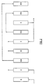
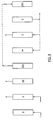
- Step R is the pressurisation step, when the cycle is the initial cycle of a run, or a repressurisation step, for the second and subsequent cycles of the run.
- A stands for the adsorption step
- CD represents the cocurrent depressurisation step
- P stands for the purge step
- E stands for the countercurrent depressurisation or evacuation step.
- steps CD and P can be carried out in the countercurrent direction, although this is less preferred.
- Step CD is also shown in dashed form to indicate that this step, although important in preferred embodiments of the invention, is optional in the embodiment illustrated in Figure 1.
- step E is used to produce the strongly adsorbed product and to provide the purge gas for purge step P.
- the line connecting the inlet end of the adsorption vessel in steps E and P is dashed to indicate that in a single vessel system the gas goes indirectly from the strongly adsorbed outlet of the adsorption vessel in step E to the inlet of the adsorption vessel in step P.
- the purge gas usually comes from a strongly adsorbed gas product storage vessel.
- the novel steps of the process illustrated in Figure 1 are steps ED1 and EP1. Together these steps constitute a pressure equalization procedure.
- ED1 stands for equalization depressurisation 1
- EP1 stands for equalization pressurisation 1.
- a dashed line connects the outlet end of the adsorption vessel to indicate that these steps are not contemporaneous in a single adsorption vessel system.
- the equalization step is represented in Figure 1 as taking place between the nonadsorbed outlet ends of the vessel (outlet-to-outlet equalization).
- this is the preferred method of equalization, other equalization techniques, such as inlet-to-inlet, outlet to inlet or inlet-to-inlet/outlet-to-outlet equalization methods can be employed.
- Conducting the equalization step after the purge step results in the removal of additional gas impurities from the vessel prior to the countercurrent depressurisation step, thus enhancing the purity of the strongly adsorbed product gas, and also results in the transfer of strongly adsorbed gas-rich gas removed from the adsorption vessel during step ED1 back into the adsorption vessel during step EP1, thus avoiding loss of strongly adsorbed product gas during the equalization step.
- step ED1 reduces the pressure in the adsorption vessel from the pressure at which the purge step is carried out to the pressure at which step E begins.
- Step EP1 serves to partially repressurise the adsorption vessel. In some preferred embodiments steps ED1, E and EP1 are carried out at subatmospheric pressures.
- the purge step can be carried out at any desired pressure between the adsorption pressure and the pressure at which step ED1 is carried out. Furthermore, when the cocurrent depressurisation step is eliminated, the pressure in the adsorption vessel can be reduced over the course of the purge step.
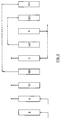
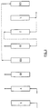
- FIG. 2 An alternative broad embodiment of the invention is illustrated in Figure 2.
- the Figure 2 process is similar to that of Figure 1, except that in the Figure 2 process, step CD is required and the equalization-depressurisation step, step ED2, is carried out before the purge step.
- the second part of the equalization step, step EP2 is substantially identical to step EP1 of the Figure 1 process.
- Step CD in the Figure 2 process serves to remove gas mixture that is relatively depleted in strongly adsorbed component
- Step ED2 serves to recover some of the strongly adsorbed component that is normally discharged from the system in the Figure 1 process.
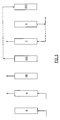
- Step 3 is a modification of the Figure 1 process wherein the cycle includes an additional equalization procedure, comprising steps ED3 and EP3.
- the principal purpose of the additional equalization is to preserve some of the energy pressure that is lost during step CD of the Figure 1 process.
- Step EP3 follows step EP1 in the cycle, since the gas introduced into the adsorption vessel during step
- EP3 is greater than the pressure in the vessel at the end of step EP1.
- Step CD is optional in the Figure 3 process.
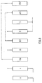
- the process shown in Figure 4 is another modification of the Figure 1 process.
- the Figure 4 process is a combination of the processes of Figures. 1 and 2.
- the ED2/EP2 equalization procedure does not preserve as much pressure energy as the ED3/ EP3 equalization procedure, but the gas transferred during the ED2/ EP2 procedure is richer in strongly adsorbed component than the gas transferred during the ED3/EP3 procedure, since it comes from the bottom section of the adsorption vessel.
- Step EP2 follows step EP1 in the cycle since the pressure in the adsorption vessel at the beginning of step EP2 is greater than the pressure in the vessel at the end of step EP1.
- Step CD is required in the Figure 4 process to distinguish this process from the process of the Figure 3 embodiment that does not include step CD.
- the Figure 5 process is a modification of the Figure 2 process. As was the case in the Figure 3 process, the Figure 5 process serves primarily to preserve some of the energy pressure that would be lost in step CD if steps ED3/EP3 were not included in the cycle. Step EP3 follows step EP2 in the cycle since the pressure in the adsorption vessel at the beginning of step EP3 is greater than the pressure in the vessel at the end of step EP2. Step CD is required in the Figure 5 process.
- the process of Figure 6 is more preferred than the processes illustrated in Figures. 1-4, since it incorporates all of the advantages of the Figures 1-4 processes into a single process.
- the Figure 6 process includes the strongly adsorbed product purification benefit of the Figure 1 process, and the pressure energy saving benefit of the process of Figure 5.
- Steps EP1, EP2 and EP3 occur in the order shown in Figure 6, since the pressure on the adsorption vessel at the beginning of step EP2 is greater than the pressure in the vessel at the end of step EP1, and the pressure in the adsorption vessel at the beginning of step EP3 is greater than the pressure in the vessel at the end of step EP2.
- Step CD is required in the Figure 6 process.
- the process of Figure 7 is a modification of the Figure 1 process.
- the Figure 7 process includes a cocurrent purge step, which is referred to as HPP (high pressure purge) to indicate that it is conducted at a higher pressure than purge step P.
- Step HPP serves to recover some of the strongly adsorbed gas component that is normally lost in step CD, by purging the adsorption vessel after step EP1 with the step CD effluent.
- the regenerated adsorbent will adsorb some of the strongly adsorbed component in the step CD effluent, thus enhancing recovery of strongly adsorbed component from the feed gas mixture.
- the process illustrated in Figure 8 is a modification of the Figure 2 process.
- the modified process includes a pre-purge pressurisation step (PP) between step ED2 and purge step P, during which the pressure in the adsorption vessel is raised by introducing thereinto strongly adsorbed gas product removed from the adsorption vessel during step E.
- This step increases the concentration of strongly adsorbed gas component in the adsorption vessel and causes additional nonadsorbed or weakly adsorbed gas component to be desorbed from the adsorbent. Because of this more nonadsorbed gas component will be purged from the adsorption vessel during step P.
- Figure 9 illustrates another modification of the process of the invention. Although the Figure 9 embodiment is illustrated as a modification of the process of Figure 2, this embodiment can also be applied to the process of Figure 1. The effect of this embodiment is to increase the duration of the purge step, thereby enhancing the purity of the strongly adsorbed product.
- the Table illustrates a preferred embodiment of the invention in which four adsorption vessels, vessels B1 to B4, are operated in parallel and 90o out of phase, and a single vacuum pump is used for all evacuation steps of the process.
- the adsorption cycle includes the eleven steps of the preferred cycle described above and illustrated in Figure 2.
- the steps of the cycle are: adsorption (AD), step 2; cocurrent depressurisation (CO), step 3; cocurrent depressurisation to purge (CP), step 4; first purge (P1), step 5; first evacuation (E1), step 6; adsorption/purge (AP), step 7; second purge (P2), step 8; third purge (P3), step 9; fourth purge (P4), step 10; second evacuation (E2), step 11; and repressurisation (RP), step 1.
- AD adsorption
- CO cocurrent depressurisation
- CP cocurrent depressurisation to purge
- step 4 first purge (P1), step 5; first evacuation (E1), step 6; adsorption/purge (AP), step 7; second purge (P2), step 8; third purge (P3), step 9; fourth purge (P4), step 10; second evacuation (E2), step 11; and repressurisation (RP), step 1.
Landscapes
- Chemical & Material Sciences (AREA)
- Engineering & Computer Science (AREA)
- Analytical Chemistry (AREA)
- General Chemical & Material Sciences (AREA)
- Oil, Petroleum & Natural Gas (AREA)
- Chemical Kinetics & Catalysis (AREA)
- Separation Of Gases By Adsorption (AREA)
Applications Claiming Priority (2)
| Application Number | Priority Date | Filing Date | Title |
|---|---|---|---|
| US234819 | 1994-04-28 | ||
| US09/234,819 US6113672A (en) | 1999-01-21 | 1999-01-21 | Multiple equalization pressure swing adsorption process |
Publications (2)
| Publication Number | Publication Date |
|---|---|
| EP1022045A2 true EP1022045A2 (de) | 2000-07-26 |
| EP1022045A3 EP1022045A3 (de) | 2002-10-16 |
Family
ID=22882961
Family Applications (1)
| Application Number | Title | Priority Date | Filing Date |
|---|---|---|---|
| EP00300292A Withdrawn EP1022045A3 (de) | 1999-01-21 | 2000-01-17 | Druckwechseladsorptionsverfahren mit vielstufigem Druckausgleich |
Country Status (2)
| Country | Link |
|---|---|
| US (1) | US6113672A (de) |
| EP (1) | EP1022045A3 (de) |
Cited By (5)
| Publication number | Priority date | Publication date | Assignee | Title |
|---|---|---|---|---|
| WO2017087167A1 (en) * | 2015-11-17 | 2017-05-26 | Exxonmobil Research And Engineering Company | Staged complementary psa system for low energy fractionation of mixed fluid |
| US10071338B2 (en) | 2015-11-17 | 2018-09-11 | Exxonmobil Research And Engineering Company | Staged pressure swing adsorption for simultaneous power plant emission control and enhanced hydrocarbon recovery |
| US10071337B2 (en) | 2015-11-17 | 2018-09-11 | Exxonmobil Research And Engineering Company | Integration of staged complementary PSA system with a power plant for CO2 capture/utilization and N2 production |
| US10125641B2 (en) | 2015-11-17 | 2018-11-13 | Exxonmobil Research And Engineering Company | Dual integrated PSA for simultaneous power plant emission control and enhanced hydrocarbon recovery |
| US10439242B2 (en) | 2015-11-17 | 2019-10-08 | Exxonmobil Research And Engineering Company | Hybrid high-temperature swing adsorption and fuel cell |
Families Citing this family (12)
| Publication number | Priority date | Publication date | Assignee | Title |
|---|---|---|---|---|
| NL1013314C2 (nl) * | 1999-10-16 | 2001-04-18 | Esselink B V | Drukwisseladsorptiewerkwijze. |
| US6527831B2 (en) * | 2000-12-29 | 2003-03-04 | Praxair Technology, Inc. | Argon purification process |
| US6565628B2 (en) * | 2001-07-23 | 2003-05-20 | Air Products And Chemicals, Inc. | Pressure swing adsorption process with reduced pressure equalization time |
| US6527830B1 (en) * | 2001-10-03 | 2003-03-04 | Praxair Technology, Inc. | Pressure swing adsorption process for co-producing nitrogen and oxygen |
| US6709486B2 (en) * | 2002-04-08 | 2004-03-23 | Air Products And Chemicals, Inc. | Pressure swing adsorption process with controlled internal depressurization flow |
| US6641645B1 (en) * | 2002-06-13 | 2003-11-04 | Air Products And Chemicals, Inc. | Vacuum swing adsorption process with controlled waste gas withdrawal |
| JP4301452B2 (ja) * | 2003-02-18 | 2009-07-22 | サンビオー2 カンパニー,リミティド | 気体濃縮方法およびその装置 |
| JP4608444B2 (ja) * | 2006-02-06 | 2011-01-12 | 日本エア・リキード株式会社 | 圧縮空気製造方法および製造装置 |
| US7695545B2 (en) | 2007-03-14 | 2010-04-13 | Air Products And Chemicals, Inc. | Adsorption process to recover hydrogen from feed gas mixtures having low hydrogen concentration |
| JP5537208B2 (ja) * | 2010-03-24 | 2014-07-02 | 大阪瓦斯株式会社 | 可燃性ガス濃縮方法 |
| US20140047978A1 (en) * | 2011-03-31 | 2014-02-20 | Uop Llc | Process for purifying a gas in a temperature swing adsorption unit |
| US8574348B2 (en) * | 2011-03-31 | 2013-11-05 | Uop Llc | Process for purifying a gas in a temperature swing adsorption unit |
Family Cites Families (25)
| Publication number | Priority date | Publication date | Assignee | Title |
|---|---|---|---|---|
| US32590A (en) * | 1861-06-18 | Improved apparatus for inserting stoppers in bottles | ||
| US3564816A (en) * | 1968-12-30 | 1971-02-23 | Union Carbide Corp | Selective adsorption process |
| US3986849A (en) * | 1975-11-07 | 1976-10-19 | Union Carbide Corporation | Selective adsorption process |
| DE2918405A1 (de) * | 1979-05-08 | 1980-11-20 | Metallgesellschaft Ag | Verfahren zur erzeugung von kohlenmonoxid und wasserstoff aus methanol |
| JPS5922625A (ja) * | 1982-07-27 | 1984-02-04 | Osaka Oxgen Ind Ltd | 一酸化炭素ガス及び窒素ガスを含む混合ガスより窒素ガスを吸着法により除去する方法 |
| CA1238868A (en) | 1983-06-20 | 1988-07-05 | Tetsuya Fujii | Method for obtaining high-purity carbon monoxide |
| US4512780A (en) * | 1983-11-08 | 1985-04-23 | Union Carbide Corporation | Pressure swing adsorption with intermediate product recovery |
| US4726816A (en) * | 1983-11-08 | 1988-02-23 | Union Carbide Corporation | Reformer-pressure swing adsorption process for the production of carbon monoxide |
| DE3346032A1 (de) * | 1983-12-20 | 1985-06-20 | Linde Ag, 6200 Wiesbaden | Druckwechseladsorptionsverfahren |
| US4705541A (en) * | 1987-02-12 | 1987-11-10 | Air Products And Chemicals, Inc. | Production of mixed gases of controlled composition by pressure swing adsorption |
| JPH0779940B2 (ja) * | 1987-09-16 | 1995-08-30 | 日本酸素株式会社 | 吸着分離法 |
| US5234472A (en) * | 1987-11-16 | 1993-08-10 | The Boc Group Plc | Separation of gas mixtures including hydrogen |
| US4892565A (en) * | 1987-12-29 | 1990-01-09 | Air Products And Chemicals, Inc. | Adsorptive separation utilizing multiple adsorption beds |
| US4915711A (en) * | 1989-05-18 | 1990-04-10 | Air Products And Chemicals, Inc. | Adsorptive process for producing two gas streams from a gas mixture |
| CA2016613C (en) * | 1989-05-18 | 1996-03-19 | Ravi Kumar | Adsorptive process for producing two gas streams from a gas mixture |
| US5106396A (en) * | 1989-12-28 | 1992-04-21 | Mitariten Michael J | Adsorption processes with intermediate product recovery using two adsorption zones |
| US5042995A (en) * | 1989-12-28 | 1991-08-27 | Uop | Pressure swing adsorption with intermediate product recovery using two adsorption zones |
| US5203888A (en) * | 1990-11-23 | 1993-04-20 | Uop | Pressure swing adsorption process with multiple desorption steps |
| US5354346A (en) * | 1992-10-01 | 1994-10-11 | Air Products And Chemicals, Inc. | Purge effluent repressurized adsorption process |
| US5248322A (en) * | 1992-10-01 | 1993-09-28 | Air Products And Chemicals, Inc. | Depressurization effluent repressurized adsorption process |
| US5294247A (en) * | 1993-02-26 | 1994-03-15 | Air Products And Chemicals, Inc. | Adsorption process to recover hydrogen from low pressure feeds |
| US5520720A (en) * | 1994-11-30 | 1996-05-28 | The Boc Group, Inc. | Pressure swing adsorption process |
| US5702504A (en) * | 1996-03-07 | 1997-12-30 | Praxair Technology, Inc. | Vacuum pressure swing adsorption process |
| US5993517A (en) * | 1998-03-17 | 1999-11-30 | The Boc Group, Inc. | Two stage pressure swing adsorption process |
| US5980857A (en) * | 1998-03-18 | 1999-11-09 | The Boc Group, Inc. | Production of carbon monoxide from syngas |
-
1999
- 1999-01-21 US US09/234,819 patent/US6113672A/en not_active Expired - Fee Related
-
2000
- 2000-01-17 EP EP00300292A patent/EP1022045A3/de not_active Withdrawn
Cited By (6)
| Publication number | Priority date | Publication date | Assignee | Title |
|---|---|---|---|---|
| WO2017087167A1 (en) * | 2015-11-17 | 2017-05-26 | Exxonmobil Research And Engineering Company | Staged complementary psa system for low energy fractionation of mixed fluid |
| US10071338B2 (en) | 2015-11-17 | 2018-09-11 | Exxonmobil Research And Engineering Company | Staged pressure swing adsorption for simultaneous power plant emission control and enhanced hydrocarbon recovery |
| US10071337B2 (en) | 2015-11-17 | 2018-09-11 | Exxonmobil Research And Engineering Company | Integration of staged complementary PSA system with a power plant for CO2 capture/utilization and N2 production |
| US10125641B2 (en) | 2015-11-17 | 2018-11-13 | Exxonmobil Research And Engineering Company | Dual integrated PSA for simultaneous power plant emission control and enhanced hydrocarbon recovery |
| US10143960B2 (en) | 2015-11-17 | 2018-12-04 | Exxonmobil Research And Engineering Company | Staged complementary PSA system for low energy fractionation of mixed fluid |
| US10439242B2 (en) | 2015-11-17 | 2019-10-08 | Exxonmobil Research And Engineering Company | Hybrid high-temperature swing adsorption and fuel cell |
Also Published As
| Publication number | Publication date |
|---|---|
| EP1022045A3 (de) | 2002-10-16 |
| US6113672A (en) | 2000-09-05 |
Similar Documents
| Publication | Publication Date | Title |
|---|---|---|
| AU646704B2 (en) | Hydrogen and carbon monoxide production by hydrocarbon steam reforming and pressure swing adsorption purification | |
| US5084075A (en) | Vacuum swing adsorption process for production of 95+% n2 from ambient air | |
| JP2744596B2 (ja) | 供給ガス混合物の比較的吸着力の弱い成分から比較的吸着力の強い成分を選択的に分離する方法 | |
| US6113672A (en) | Multiple equalization pressure swing adsorption process | |
| US5792239A (en) | Separation of gases by pressure swing adsorption | |
| US4892565A (en) | Adsorptive separation utilizing multiple adsorption beds | |
| JP2634138B2 (ja) | 真空スイング吸着方法によるガス成分の分離法 | |
| KR100254295B1 (ko) | 단일 흡착 베드를 이용한 압력 스윙 흡착 방법 | |
| EP0714690B1 (de) | Druckwechsel Adsorptionsverfahren | |
| EP1101522B1 (de) | Druckwechseladsorptionsverfahren | |
| EP1004342B1 (de) | Druckwechseladsorptionsverfahren zur Gastrennung und Vorrichtung unter Verwendung eines einzelnen Adsorbers und von Produktrückführung | |
| EP1018359A2 (de) | Druckwechseladsorptionsverfahren und -system mit Produktbehälter(n) | |
| EP2823872A2 (de) | Druckwechsel-Adsorptionsverfahren | |
| JP3073917B2 (ja) | 同時段階圧力変化式吸着方法 | |
| JP3902416B2 (ja) | ガス分離方法 | |
| EP1175934A2 (de) | Verbessertes Verfahren zur Sauerstofferzeugung | |
| US5993517A (en) | Two stage pressure swing adsorption process | |
| EP0193716A2 (de) | Adsorptive Trennung von Gasmischungen aus Methan und Kohlendioxid | |
| JPS6245315A (ja) | 圧力交代吸着方法 | |
| US6083299A (en) | High pressure purge pressure swing adsorption process | |
| EP0529513A2 (de) | Druckwechseladsorptionsverfahren für Wasserstoff mit hoher Produktivität | |
| JP2001335305A (ja) | Coガス/h2ガス回収装置及びcoガス/h2ガス回収方法 | |
| US4722742A (en) | Pressure swing adsorption | |
| KR19980016382A (ko) | 압력변동흡착식 고순도 이산화탄소 제조방법 | |
| JP2000317245A (ja) | ガスの分離精製方法 |
Legal Events
| Date | Code | Title | Description |
|---|---|---|---|
| PUAI | Public reference made under article 153(3) epc to a published international application that has entered the european phase |
Free format text: ORIGINAL CODE: 0009012 |
|
| AK | Designated contracting states |
Kind code of ref document: A2 Designated state(s): AT BE CH CY DE DK ES FI FR GB GR IE IT LI LU MC NL PT SE |
|
| AX | Request for extension of the european patent |
Free format text: AL;LT;LV;MK;RO;SI |
|
| PUAL | Search report despatched |
Free format text: ORIGINAL CODE: 0009013 |
|
| AK | Designated contracting states |
Kind code of ref document: A3 Designated state(s): AT BE CH CY DE DK ES FI FR GB GR IE IT LI LU MC NL PT SE |
|
| AX | Request for extension of the european patent |
Free format text: AL;LT;LV;MK;RO;SI |
|
| AKX | Designation fees paid | ||
| REG | Reference to a national code |
Ref country code: DE Ref legal event code: 8566 |
|
| STAA | Information on the status of an ep patent application or granted ep patent |
Free format text: STATUS: THE APPLICATION IS DEEMED TO BE WITHDRAWN |
|
| 18D | Application deemed to be withdrawn |
Effective date: 20030417 |