EP1021372B1 - Verfahren zur rückgewinnung von schwefel aus h2s enthaltenden gasen - Google Patents
Verfahren zur rückgewinnung von schwefel aus h2s enthaltenden gasen Download PDFInfo
- Publication number
- EP1021372B1 EP1021372B1 EP98945885A EP98945885A EP1021372B1 EP 1021372 B1 EP1021372 B1 EP 1021372B1 EP 98945885 A EP98945885 A EP 98945885A EP 98945885 A EP98945885 A EP 98945885A EP 1021372 B1 EP1021372 B1 EP 1021372B1
- Authority
- EP
- European Patent Office
- Prior art keywords
- gas
- solvent
- liquid
- reactor
- accordance
- Prior art date
- Legal status (The legal status is an assumption and is not a legal conclusion. Google has not performed a legal analysis and makes no representation as to the accuracy of the status listed.)
- Expired - Lifetime
Links
- NINIDFKCEFEMDL-UHFFFAOYSA-N Sulfur Chemical compound [S] NINIDFKCEFEMDL-UHFFFAOYSA-N 0.000 title claims abstract description 74
- 238000000034 method Methods 0.000 title claims abstract description 54
- 239000011593 sulfur Substances 0.000 title claims description 48
- 229910052717 sulfur Inorganic materials 0.000 title claims description 48
- 239000002904 solvent Substances 0.000 claims abstract description 131
- 239000007789 gas Substances 0.000 claims abstract description 112
- 239000006096 absorbing agent Substances 0.000 claims abstract description 52
- 239000007791 liquid phase Substances 0.000 claims abstract description 27
- 239000003054 catalyst Substances 0.000 claims abstract description 25
- DNIAPMSPPWPWGF-UHFFFAOYSA-N Propylene glycol Chemical compound CC(O)CO DNIAPMSPPWPWGF-UHFFFAOYSA-N 0.000 claims abstract description 21
- LYCAIKOWRPUZTN-UHFFFAOYSA-N Ethylene glycol Chemical compound OCCO LYCAIKOWRPUZTN-UHFFFAOYSA-N 0.000 claims abstract description 16
- JUJWROOIHBZHMG-UHFFFAOYSA-N Pyridine Chemical compound C1=CC=NC=C1 JUJWROOIHBZHMG-UHFFFAOYSA-N 0.000 claims abstract description 12
- AWJUIBRHMBBTKR-UHFFFAOYSA-N isoquinoline Chemical compound C1=NC=CC2=CC=CC=C21 AWJUIBRHMBBTKR-UHFFFAOYSA-N 0.000 claims abstract description 8
- UMJSCPRVCHMLSP-UHFFFAOYSA-N pyridine Natural products COC1=CC=CN=C1 UMJSCPRVCHMLSP-UHFFFAOYSA-N 0.000 claims abstract description 6
- 239000007788 liquid Substances 0.000 claims description 73
- 238000006243 chemical reaction Methods 0.000 claims description 65
- IJGRMHOSHXDMSA-UHFFFAOYSA-N Atomic nitrogen Chemical compound N#N IJGRMHOSHXDMSA-UHFFFAOYSA-N 0.000 claims description 19
- -1 acetamidoalkyl Chemical group 0.000 claims description 19
- 239000012071 phase Substances 0.000 claims description 19
- MTHSVFCYNBDYFN-UHFFFAOYSA-N diethylene glycol Chemical compound OCCOCCO MTHSVFCYNBDYFN-UHFFFAOYSA-N 0.000 claims description 15
- 239000000567 combustion gas Substances 0.000 claims description 11
- 229910052757 nitrogen Inorganic materials 0.000 claims description 9
- 239000002815 homogeneous catalyst Substances 0.000 claims description 8
- 125000004432 carbon atom Chemical group C* 0.000 claims description 6
- LCZVSXRMYJUNFX-UHFFFAOYSA-N 2-[2-(2-hydroxypropoxy)propoxy]propan-1-ol Chemical compound CC(O)COC(C)COC(C)CO LCZVSXRMYJUNFX-UHFFFAOYSA-N 0.000 claims description 5
- 125000000218 acetic acid group Chemical group C(C)(=O)* 0.000 claims description 5
- 125000003668 acetyloxy group Chemical group [H]C([H])([H])C(=O)O[*] 0.000 claims description 5
- SZXQTJUDPRGNJN-UHFFFAOYSA-N dipropylene glycol Chemical compound OCCCOCCCO SZXQTJUDPRGNJN-UHFFFAOYSA-N 0.000 claims description 5
- 238000002844 melting Methods 0.000 claims description 5
- 230000008018 melting Effects 0.000 claims description 5
- 125000002496 methyl group Chemical group [H]C([H])([H])* 0.000 claims description 5
- ZIBGPFATKBEMQZ-UHFFFAOYSA-N triethylene glycol Chemical compound OCCOCCOCCO ZIBGPFATKBEMQZ-UHFFFAOYSA-N 0.000 claims description 5
- 125000002887 hydroxy group Chemical group [H]O* 0.000 claims description 4
- RTZKZFJDLAIYFH-UHFFFAOYSA-N Diethyl ether Chemical class CCOCC RTZKZFJDLAIYFH-UHFFFAOYSA-N 0.000 claims description 3
- QVHMSMOUDQXMRS-UHFFFAOYSA-N PPG n4 Chemical compound CC(O)COC(C)COC(C)COC(C)CO QVHMSMOUDQXMRS-UHFFFAOYSA-N 0.000 claims description 3
- UWHCKJMYHZGTIT-UHFFFAOYSA-N Tetraethylene glycol, Natural products OCCOCCOCCOCCO UWHCKJMYHZGTIT-UHFFFAOYSA-N 0.000 claims description 3
- 125000001495 ethyl group Chemical group [H]C([H])([H])C([H])([H])* 0.000 claims description 3
- 125000004029 hydroxymethyl group Chemical group [H]OC([H])([H])* 0.000 claims description 3
- 125000000738 acetamido group Chemical group [H]C([H])([H])C(=O)N([H])[*] 0.000 claims description 2
- 125000004183 alkoxy alkyl group Chemical group 0.000 claims description 2
- 125000003545 alkoxy group Chemical group 0.000 claims description 2
- 125000003282 alkyl amino group Chemical group 0.000 claims description 2
- 125000004103 aminoalkyl group Chemical group 0.000 claims description 2
- 238000009835 boiling Methods 0.000 claims description 2
- 125000000118 dimethyl group Chemical group [H]C([H])([H])* 0.000 claims description 2
- 150000002170 ethers Chemical class 0.000 claims description 2
- 125000002768 hydroxyalkyl group Chemical group 0.000 claims description 2
- 125000002924 primary amino group Chemical group [H]N([H])* 0.000 claims description 2
- 229910052799 carbon Inorganic materials 0.000 claims 2
- 238000004064 recycling Methods 0.000 claims 2
- MVQVNTPHUGQQHK-UHFFFAOYSA-N 3-pyridinemethanol Chemical group OCC1=CC=CN=C1 MVQVNTPHUGQQHK-UHFFFAOYSA-N 0.000 claims 1
- 150000005218 dimethyl ethers Chemical class 0.000 claims 1
- 239000012074 organic phase Substances 0.000 claims 1
- RAHZWNYVWXNFOC-UHFFFAOYSA-N Sulphur dioxide Chemical compound O=S=O RAHZWNYVWXNFOC-UHFFFAOYSA-N 0.000 abstract description 206
- RWSOTUBLDIXVET-UHFFFAOYSA-N Dihydrogen sulfide Chemical compound S RWSOTUBLDIXVET-UHFFFAOYSA-N 0.000 abstract description 159
- 229910000037 hydrogen sulfide Inorganic materials 0.000 abstract description 146
- 239000003345 natural gas Substances 0.000 abstract description 9
- 150000003512 tertiary amines Chemical class 0.000 abstract description 6
- 239000007795 chemical reaction product Substances 0.000 abstract description 2
- 229920000151 polyglycol Polymers 0.000 abstract description 2
- 239000010695 polyglycol Substances 0.000 abstract description 2
- XLYOFNOQVPJJNP-UHFFFAOYSA-N water Substances O XLYOFNOQVPJJNP-UHFFFAOYSA-N 0.000 description 68
- VNWKTOKETHGBQD-UHFFFAOYSA-N methane Chemical compound C VNWKTOKETHGBQD-UHFFFAOYSA-N 0.000 description 14
- 239000000047 product Substances 0.000 description 12
- 239000000203 mixture Substances 0.000 description 11
- SBASXUCJHJRPEV-UHFFFAOYSA-N 2-(2-methoxyethoxy)ethanol Chemical compound COCCOCCO SBASXUCJHJRPEV-UHFFFAOYSA-N 0.000 description 10
- 238000010586 diagram Methods 0.000 description 10
- 229930195733 hydrocarbon Natural products 0.000 description 10
- 150000002430 hydrocarbons Chemical class 0.000 description 10
- 238000002485 combustion reaction Methods 0.000 description 9
- 239000000446 fuel Substances 0.000 description 9
- 239000000243 solution Substances 0.000 description 9
- 239000000376 reactant Substances 0.000 description 7
- ZMANZCXQSJIPKH-UHFFFAOYSA-N Triethylamine Chemical compound CCN(CC)CC ZMANZCXQSJIPKH-UHFFFAOYSA-N 0.000 description 6
- QVGXLLKOCUKJST-UHFFFAOYSA-N atomic oxygen Chemical compound [O] QVGXLLKOCUKJST-UHFFFAOYSA-N 0.000 description 6
- 150000001875 compounds Chemical class 0.000 description 6
- 239000003960 organic solvent Substances 0.000 description 6
- 229910052760 oxygen Inorganic materials 0.000 description 6
- 239000001301 oxygen Substances 0.000 description 6
- 239000002918 waste heat Substances 0.000 description 6
- 125000000217 alkyl group Chemical group 0.000 description 5
- 238000012856 packing Methods 0.000 description 4
- 239000004071 soot Substances 0.000 description 4
- 238000010521 absorption reaction Methods 0.000 description 3
- 150000001412 amines Chemical class 0.000 description 3
- 125000003118 aryl group Chemical group 0.000 description 3
- 230000015572 biosynthetic process Effects 0.000 description 3
- 238000013461 design Methods 0.000 description 3
- 150000002334 glycols Chemical class 0.000 description 3
- BWHMMNNQKKPAPP-UHFFFAOYSA-L potassium carbonate Chemical class [K+].[K+].[O-]C([O-])=O BWHMMNNQKKPAPP-UHFFFAOYSA-L 0.000 description 3
- 238000011084 recovery Methods 0.000 description 3
- 239000002002 slurry Substances 0.000 description 3
- 239000007787 solid Substances 0.000 description 3
- 125000001424 substituent group Chemical group 0.000 description 3
- 238000011144 upstream manufacturing Methods 0.000 description 3
- CURLTUGMZLYLDI-UHFFFAOYSA-N Carbon dioxide Chemical compound O=C=O CURLTUGMZLYLDI-UHFFFAOYSA-N 0.000 description 2
- IAYPIBMASNFSPL-UHFFFAOYSA-N Ethylene oxide Chemical compound C1CO1 IAYPIBMASNFSPL-UHFFFAOYSA-N 0.000 description 2
- JLTDJTHDQAWBAV-UHFFFAOYSA-N N,N-dimethylaniline Chemical compound CN(C)C1=CC=CC=C1 JLTDJTHDQAWBAV-UHFFFAOYSA-N 0.000 description 2
- GOOHAUXETOMSMM-UHFFFAOYSA-N Propylene oxide Chemical compound CC1CO1 GOOHAUXETOMSMM-UHFFFAOYSA-N 0.000 description 2
- 229910000288 alkali metal carbonate Inorganic materials 0.000 description 2
- 150000008041 alkali metal carbonates Chemical class 0.000 description 2
- PNEYBMLMFCGWSK-UHFFFAOYSA-N aluminium oxide Inorganic materials [O-2].[O-2].[O-2].[Al+3].[Al+3] PNEYBMLMFCGWSK-UHFFFAOYSA-N 0.000 description 2
- 238000001311 chemical methods and process Methods 0.000 description 2
- 238000010276 construction Methods 0.000 description 2
- 239000002826 coolant Substances 0.000 description 2
- 238000001816 cooling Methods 0.000 description 2
- 239000000498 cooling water Substances 0.000 description 2
- 239000013078 crystal Substances 0.000 description 2
- 230000007613 environmental effect Effects 0.000 description 2
- WGCNASOHLSPBMP-UHFFFAOYSA-N hydroxyacetaldehyde Natural products OCC=O WGCNASOHLSPBMP-UHFFFAOYSA-N 0.000 description 2
- 239000000463 material Substances 0.000 description 2
- CRVGTESFCCXCTH-UHFFFAOYSA-N methyl diethanolamine Chemical compound OCCN(C)CCO CRVGTESFCCXCTH-UHFFFAOYSA-N 0.000 description 2
- 239000011541 reaction mixture Substances 0.000 description 2
- 238000000926 separation method Methods 0.000 description 2
- 229940086542 triethylamine Drugs 0.000 description 2
- 125000004169 (C1-C6) alkyl group Chemical group 0.000 description 1
- HXKKHQJGJAFBHI-UHFFFAOYSA-N 1-aminopropan-2-ol Chemical compound CC(O)CN HXKKHQJGJAFBHI-UHFFFAOYSA-N 0.000 description 1
- GIAFURWZWWWBQT-UHFFFAOYSA-N 2-(2-aminoethoxy)ethanol Chemical compound NCCOCCO GIAFURWZWWWBQT-UHFFFAOYSA-N 0.000 description 1
- HZAXFHJVJLSVMW-UHFFFAOYSA-N 2-Aminoethan-1-ol Chemical compound NCCO HZAXFHJVJLSVMW-UHFFFAOYSA-N 0.000 description 1
- LCGLNKUTAGEVQW-UHFFFAOYSA-N Dimethyl ether Chemical compound COC LCGLNKUTAGEVQW-UHFFFAOYSA-N 0.000 description 1
- VGGSQFUCUMXWEO-UHFFFAOYSA-N Ethene Chemical compound C=C VGGSQFUCUMXWEO-UHFFFAOYSA-N 0.000 description 1
- WUGQZFFCHPXWKQ-UHFFFAOYSA-N Propanolamine Chemical compound NCCCO WUGQZFFCHPXWKQ-UHFFFAOYSA-N 0.000 description 1
- 239000002253 acid Substances 0.000 description 1
- 238000013459 approach Methods 0.000 description 1
- 239000007864 aqueous solution Substances 0.000 description 1
- 239000002585 base Substances 0.000 description 1
- 230000008033 biological extinction Effects 0.000 description 1
- 230000015556 catabolic process Effects 0.000 description 1
- 230000003197 catalytic effect Effects 0.000 description 1
- 239000003245 coal Substances 0.000 description 1
- 239000003034 coal gas Substances 0.000 description 1
- 235000009508 confectionery Nutrition 0.000 description 1
- 238000000151 deposition Methods 0.000 description 1
- ZBCBWPMODOFKDW-UHFFFAOYSA-N diethanolamine Chemical compound OCCNCCO ZBCBWPMODOFKDW-UHFFFAOYSA-N 0.000 description 1
- 229910001873 dinitrogen Inorganic materials 0.000 description 1
- 238000007599 discharging Methods 0.000 description 1
- 230000002349 favourable effect Effects 0.000 description 1
- 239000002803 fossil fuel Substances 0.000 description 1
- 239000003502 gasoline Substances 0.000 description 1
- 230000005484 gravity Effects 0.000 description 1
- 231100001261 hazardous Toxicity 0.000 description 1
- 238000010438 heat treatment Methods 0.000 description 1
- 239000001257 hydrogen Substances 0.000 description 1
- 229910052739 hydrogen Inorganic materials 0.000 description 1
- 125000004435 hydrogen atom Chemical class [H]* 0.000 description 1
- 239000012535 impurity Substances 0.000 description 1
- 239000011261 inert gas Substances 0.000 description 1
- 238000002347 injection Methods 0.000 description 1
- 239000007924 injection Substances 0.000 description 1
- 229940102253 isopropanolamine Drugs 0.000 description 1
- 239000003077 lignite Substances 0.000 description 1
- 238000004519 manufacturing process Methods 0.000 description 1
- 238000002156 mixing Methods 0.000 description 1
- 150000002894 organic compounds Chemical class 0.000 description 1
- 150000002898 organic sulfur compounds Chemical class 0.000 description 1
- 230000003647 oxidation Effects 0.000 description 1
- 238000007254 oxidation reaction Methods 0.000 description 1
- 239000003208 petroleum Substances 0.000 description 1
- 238000005191 phase separation Methods 0.000 description 1
- 238000006116 polymerization reaction Methods 0.000 description 1
- 229910000027 potassium carbonate Inorganic materials 0.000 description 1
- 150000003141 primary amines Chemical class 0.000 description 1
- YPBOMIRJMVJVRW-UHFFFAOYSA-N pyridin-3-ylmethanol Chemical group OCC1=CC=CN=C1.OCC1=CC=CN=C1 YPBOMIRJMVJVRW-UHFFFAOYSA-N 0.000 description 1
- 238000010791 quenching Methods 0.000 description 1
- 239000002994 raw material Substances 0.000 description 1
- 230000008929 regeneration Effects 0.000 description 1
- 238000011069 regeneration method Methods 0.000 description 1
- 238000003303 reheating Methods 0.000 description 1
- 238000007142 ring opening reaction Methods 0.000 description 1
- 230000000630 rising effect Effects 0.000 description 1
- 229920006395 saturated elastomer Polymers 0.000 description 1
- 150000003335 secondary amines Chemical class 0.000 description 1
- 239000007790 solid phase Substances 0.000 description 1
- 239000002594 sorbent Substances 0.000 description 1
- 239000000126 substance Substances 0.000 description 1
- 238000006467 substitution reaction Methods 0.000 description 1
- 125000004434 sulfur atom Chemical group 0.000 description 1
- 150000003464 sulfur compounds Chemical class 0.000 description 1
- 231100000331 toxic Toxicity 0.000 description 1
- 230000002588 toxic effect Effects 0.000 description 1
- 238000012546 transfer Methods 0.000 description 1
- 125000005270 trialkylamine group Chemical group 0.000 description 1
- IMFACGCPASFAPR-UHFFFAOYSA-N tributylamine Chemical compound CCCCN(CCCC)CCCC IMFACGCPASFAPR-UHFFFAOYSA-N 0.000 description 1
- 238000010977 unit operation Methods 0.000 description 1
Images




Classifications
-
- C—CHEMISTRY; METALLURGY
- C01—INORGANIC CHEMISTRY
- C01B—NON-METALLIC ELEMENTS; COMPOUNDS THEREOF; METALLOIDS OR COMPOUNDS THEREOF NOT COVERED BY SUBCLASS C01C
- C01B17/00—Sulfur; Compounds thereof
- C01B17/02—Preparation of sulfur; Purification
- C01B17/04—Preparation of sulfur; Purification from gaseous sulfur compounds including gaseous sulfides
- C01B17/05—Preparation of sulfur; Purification from gaseous sulfur compounds including gaseous sulfides by wet processes
-
- B—PERFORMING OPERATIONS; TRANSPORTING
- B01—PHYSICAL OR CHEMICAL PROCESSES OR APPARATUS IN GENERAL
- B01D—SEPARATION
- B01D53/00—Separation of gases or vapours; Recovering vapours of volatile solvents from gases; Chemical or biological purification of waste gases, e.g. engine exhaust gases, smoke, fumes, flue gases, aerosols
- B01D53/34—Chemical or biological purification of waste gases
- B01D53/74—General processes for purification of waste gases; Apparatus or devices specially adapted therefor
- B01D53/86—Catalytic processes
- B01D53/8603—Removing sulfur compounds
- B01D53/8612—Hydrogen sulfide
Definitions
- This invention lies in the field of sulfur removal and recovery, and particularly in the treatment of sour gases and other gases in the chemical process industry that contain hydrogen sulfide.
- the traditional method for converting hydrogen sulfide in natural gases and in gaseous plant effluents is the Claus process, in which part of the hydrogen sulfide is burned in air to form sulfur dioxide and water: 2 H 2 S + 3 O 2 ⁇ 2 SO 2 + 2 H 2 O and the sulfur dioxide thus produced is reacted with further hydrogen sulfide to form sulfur and additional water: 2 H 2 S + SO 2 ⁇ 3 / x S x + 2 H 2 O
- the symbol " x " in Reaction B is used to denote that the elemental sulfur exists in a mixture of molecular species varying in the number of sulfur atoms per molecule.
- the furnace (Reaction A) in the Claus process is operated with a fuel-rich mixture, converting only one-third of the H 2 S to SO 2 .
- the fuel-rich atmosphere results in the partial conversion of hydrocarbons that are present in the H 2 S feed to such compounds as COS and CS 2 , which lessen the yield of elemental sulfur and are themselves hazardous.
- the fuel-rich atmosphere also promotes the breakdown of aromatics to soot. For high sulfur recovery, precise control of the overall stoichiometry is needed, and this is made especially difficult when considerable amounts of CO 2 and other inerts are present.
- Part of Reaction B occurs in the furnace and the rest is conducted in a heterogeneous system in which the reaction mixture is gas-phase and contacts a solid activated alumina catalyst of a sort well known to those skilled in the art of the Claus process. With continued use, the alumina catalyst fouls and becomes otherwise deactivated over time. This requires plant shutdown, loss of process time, and the cost of regeneration or replacement of the catalyst, together with the associated labor costs.
- a further disadvantage of Reaction B is that it is equilibrium-limited at temperatures above the dewpoint of sulfur, and despite being performed in two to four stages, the reaction leaves 2% to 5% of the H 2 S and SO 2 unreacted.
- Each stage requires a separate condenser to remove the elemental sulfur, and these condensers require a large heat-exchange area and reheating of the gas leaving each but the last condenser.
- the steam generated by each condenser is low in pressure, limiting its usefulness. Additional costs are entailed in treating the tail gas in which the sulfur content must be reduced by ten to twenty times.
- reaction 2 H 2 S + SO 2 ⁇ 3 S + 2 H 2 O is conducted with excess H 2 S in the liquid phase in the presence of a homogeneous liquid-phase Claus catalyst, at a temperature above the melting point of sulfur but low enough to keep the reaction in the liquid phase, and upstream of the furnace where unreacted H 2 S is combusted to produce the SO 2 that is consumed in reaction (I).
- the H 2 S that is combusted in the furnace is the excess H 2 S that passes unreacted through the liquid-phase reaction, optionally supplemented by H 2 S from an H 2 S-containing stream that bypasses the reaction (I) reactor.
- the SO 2 in the furnace combustion gas is recycled to the reaction (I) reactor either as a gas or dissolved in a solvent, and in any case serves as the entire SO 2 feed to the reaction.
- FIG. 1 the invention as shown in FIG. 1 proceeds as follows:
- the continuous-flow reactor 1 described above serves as the first stage.
- H 2 S contacts SO 2 in the presence of an organic liquid that promotes the conversion of these reactants to elemental sulfur and water according to Reaction I.
- the reaction occurs in the liquid phase, and the liquid contains a homogeneous liquid-phase catalyst, i . e ., one that is dissolved in the liquid reaction mixture.
- the stream When the H 2 S-containing stream is fed to the reactor as a gas, the stream preferably contains at least about 20 mole percent H 2 S and preferably from about 25 mole percent to substantially 100 mole percent H 2 S.
- the concentration of H 2 S entering the reactor is not critical to this invention and can vary widely, but is preferably greater than the H 2 S concentration in a typical natural gas stream or process stream from a fossil-fuel treatment plant. If desired, the concentration is readily increased by selectively absorbing the H 2 S from the gas stream into a solvent, then stripping the H 2 S from the solvent.
- the solvent can be the same solvent used in the continuous-flow reactor. Alternatively, a different solvent can be used in a separate flow loop.
- the solvent may also contain water produced by Reaction I above, and the stripper will preferably volatilize the water from the solvent simultaneously with the stripping of the H 2 S.
- the emerging gas stream will then contain both H 2 S and water vapor.
- the H 2 S-containing stream fed to the continuous-flow reactor 1 will be either partially or entirely in the gas phase in the concentration ranges indicated above.
- the H 2 S-containing gas mixture prior to concentration is typically a sour gas whose H 2 S content can vary widely, ranging from as low as 0.01 mole percent to levels of 1.0 mole percent and above.
- the SO 2 enters the continuous-flow reactor as a liquid
- it can be rendered in liquid form by being dissolved in the solvent that is used in the SO 2 absorber (identified above as the third stage) at a concentration of at least about 1 % by weight, more preferably from about 1% to about 40% by weight, and most preferably from about 3% to about 10% by weight.
- it can be dissolved prior to or upon entering the reactor in a solvent that is independently circulated through the reactor.
- the solvents used in the practice of this invention are preferably of moderate to low viscosity, as well as being chemically inert to the reactants, products or other components with which they come in contact. For any particular solvent, this will depend on the particular unit of the process in which the solvent is used.
- Preferred solvents are those that readily absorb H 2 S and SO 2 , that do not form an azeotrope with water, that are chemically inert to the reactants, liquid sulfur and water, and that have limited mutual solubility with liquid sulfur.
- Preferred solvents are those that are derived from ethylene oxide or propylene oxide by a ring-opening reaction with a co-reactant having an active hydrogen, provided that the resulting solvent is inert with respect to both sulfur and SO 2 .
- glycols and glycol ethers derived from ethylene oxide or propylene oxide, particularly ethers of ethylene glycol, diethylene glycol, triethylene glycol, tetraethylene glycol, propylene glycol, dipropylene glycol, tripropylene glycol, and tetrapropylene glycol.
- Specific examples are the monomethyl, dimethyl, monoethyl, and diethyl ethers of these glycols.
- Additional solvents capable of use in this invention are various trialkyl and alkyldialkanol amines such as triethyl amine and methyldiethanol amine, and liquid alkyl and aryl quaternary ammonium salts. Primary and secondary amines react with elemental sulfur and are therefore not suitable.
- tertiary amines are preferred, particularly lower alkyl-substituted tertiary amines, lower alkyl- and aryl-substituted tertiary amines, and aryl-substituted tertiary amines, including those in which the amine nitrogen is an aromatic ring atom.
- tertiary amines that do not contain an aromatic ring nitrogen are N,N-dimethyl aniline, triethylamine, tri- n -butylamine, and mixed trialkylamines.
- Preferred catalysts are those that do contain an aromatic ring nitrogen that is not sterically hindered by substitutions at carbon atoms adjacent to the ring nitrogen.
- Particularly preferred catalysts are pyridine and isoquinoline, optionally substituted at one or more sites other than carbon atoms adjacent to the ring nitrogen with a polar group.
- suitable polar groups substituents are hydroxyl, hydroxyalkyl, acetamido, acetamidoalkyl, acetyl, acetylalkyl, acetyloxy, acetyloxyalkyl, alkoxy, alkoxyalkyl, amino, alkylamino, and aminoalkyl groups.
- alkyl refers to lower alkyl, i . e ., C 1 -C 6 alkyl, straight- or branched-chain, provided that the alkyl group does not fully mask the polar character of the substituent.
- Preferred alkyl groups are C 1 -C 4 , particularly methyl and ethyl.
- Particularly preferred substituents are hydroxyl, hydroxymethyl, acetamido, acetamidomethyl, acetyl, acetylmethyl, acetyloxy, and acetyloxymethyl.
- the most preferred ring structure is pyridine, and the most preferred catalyst is 3-(hydroxymethyl)pyridine (3-pyridyl carbinol).
- concentration of catalyst in the solvent is not critical to the invention and can vary widely.
- a typical range of concentration is from about 0.1 % to about 1.0% by weight, although concentrations above and below this amount can be used effectively as well.
- the H 2 S entering the reactor section 1 will frequently contain small-to-moderate concentrations of other gases such as CO2, hydrocarbons, mercaptans, COS and CS 2 . Such compounds are inert in the Stage 1 reaction, and will pass through the reactor 1 unchanged, together with the excess H 2 S.
- gases such as CO2, hydrocarbons, mercaptans, COS and CS 2 .
- the flow through the reactor can be either cocurrent or countercurrent.
- the reactor is preferably a loosely packed bed of inert column packing designed for enhanced turbulent solid-liquid contact.
- column packings that can be used are Raschig rings, Lessing rings, Berl saddles, Intalox saddles, Tellerettes, Pall rings, and various designs of structured packing that are readily available in the industry.
- Countercurrent flow reactors are likewise of conventional design. Packed columns such as those described above for cocurrent flow can be used for countercurrent flow as well. Other alternatives, however, are plate columns with plates such as bubble cap plates, sieve plates, valve plates and baffle plates.
- the residence time within the reactor is not critical and can vary widely but should be sufficient for SO 2 to react to extinction. In view of the excess H 2 S, this will typically be achieved with a gas-phase residence time ranging from about 0.5 second to about 30 seconds, preferably from about 1 second to about 20 seconds, more preferably from about 1 second to about 15 seconds. In the particularly preferred practice of this invention, the gas-phase residence time is from about 2 seconds to about 10 seconds.
- the temperature and pressure of the reaction are usually selected to produce elemental sulfur as a separate, clear yellow liquid phase. This is generally achieved by conducting the reaction at a temperature between the melting point of sulfur (119°C) and its polymerization temperature (about 155°C). A preferred temperature range is from about 125°C to about 145°C. It is then also preferred that at least some of the water produced by the reaction be volatilized in the reactor to leave the reactor as part of the off-gas. However, it is possible to operate the reactor below the melting point of sulfur if provision is made for handling the solid, crystalline product as it forms. In a broader sense, therefore, the reactor can be operated within a temperature range of from about 45°C to about 150°C. Preferred temperatures, however, are those within the ranges cited above. The temperature is maintained in the desired range by allowing water to evaporate from the solvent or by suitable indirect heat exchange. Means of achieving this will be readily apparent to those skilled in reactor design.
- the furnace 2 described above as the second stage of the process of this invention combusts the unreacted (excess) hydrogen sulfide from the continuous-flow reactor with an oxygen-containing gas.
- Air is the most convenient, but other oxygen-containing gas mixtures (in which essentially all other components thereof are inert) or oxygen itself can be used.
- the furnace is preferably operated to result in little or no O 2 in the combustion gas leaving the furnace.
- the furnace is operated at a slight excess of oxygen rather than H 2 S.
- Gaseous components of the H 2 S feed such as hydrocarbons, mercaptans, COS, and CS 2 are burned completely under these conditions. Sulfur-containing compounds yield their sulfur as SO 2 .
- CO 2 is a component of the feed, it passes through the furnace unchanged and hinders the combustion only if its concentration is excessive.
- the H 2 S feed to the furnace 2 will include all of the H 2 S-containing gas that has bypassed the reaction stage 1. When this is done, it is still preferable to maintain excess H 2 S in the reaction stage 1, although perhaps less than when all of the H 2 S fed to the process is directed to the reaction stage. In processes that include H 2 S bypass, up to about 30%, or preferably about 10% to about 30%, of the H 2 S feed to the process can be bypassed. Whether or not an H 2 S bypass is used, the total H 2 S fed to the process as a whole (including the bypass H 2 S if one is present) is preferably at an excess of approximately 50% relative to the SO 2 fed to the reaction stage 1, with reference to the stoichiometry of reaction (I).
- the SO 2 absorber 3 the third stage of the process of the invention, recovers the SO 2 from the stack gas in a form in which it can be recycled, or further prepared for recycle, back to the reaction stage 1.
- the absorbing solvent may be the same solvent used in the reaction stage 1 and thereby returned to the reactor as a carrier of the SO 2 .
- the absorbing solvent may be part of a separate loop from which the SO 2 is first stripped before being fed to the reactor.
- the solvent will also contain the liquid-phase catalyst for reaction (I).
- the absorbing solvent When the absorbing solvent is recovered from the product stream leaving the reaction stage 1, the absorbing solvent is preferably stripped of the net water added to the solvent in stage 1 and substantially all dissolved H 2 S prior to the entry of the solvent into the absorber.
- the solubility of SO 2 is very high. These solvents absorb substantially all of the SO 2 from the combustion gas.
- the SO 2 in the tail gas leaving the absorber can be reduced to 10-100 parts per million (ppm) by volume, which is well below current emission limits.
- the solubility of CO 2 in these solvents is relatively low and the amount of CO 2 absorbed from the combustion gas is insignificant.
- the tail gas from the SO 2 absorber is thus substantially free of H 2 S and SO 2 .
- the term "substantially free” is used in this context to include trace amounts of each gas, such as amounts in the range of approximately 10-100 ppm or less for SO 2 and approximately 0.01-1.0 ppm or less for H 2 S.
- FIGS. 2 through 6 are detailed process-flow diagrams for particular sulfur recovery processes within the scope of the invention.
- FIG. 2 is a process-flow diagram for a plant designed for a reaction using liquid-phase SO 2 and a liquid-phase catalyst, with a feed of sour natural gas 11 at 1,000 pounds per square inch absolute (psia) (68 atmospheres) containing 2.7 mole percent H 2 S and 0.1 mole percent H 2 O.
- the sour gas is first passed through an absorber 12 in upward flow, the absorber being a packed tower with counter-current flow of gas and liquid.
- the solvent 13 with dissolved catalyst enters the top of the absorber 12 at about 40°C (104°F) at a rate of about 3 kg per 100 moles of feed gas, or about 1.5 times the minimum flow required for absorption of the H 2 S in the feed gas.
- the gas stream rising past the packed section of the absorber 12 (still within the absorber) is equilibrated with water present in the incoming solvent stream 13 and contains about 10 ppm (by volume) of DGM.
- a small stream of water 15 is introduced to absorb remaining solvent and prevent loss of the solvent into the sweet (H 2 S-free) gas 16 leaving the top of the absorber.
- the H 2 S-rich solvent 17 leaving the absorber contains almost all of the H 2 S and H 2 O in the sour gas feed.
- the H 2 S-rich solvent passes through a valve 21 where its pressure is dropped to near atmospheric, then preheated in a heat exchanger 22 prior to entering the solvent stripper 23 as a side stream.
- Entering the top of the solvent stripper 23 is a stream of wet solvent 24 which also contains a small amount of H 2 S.
- the stream of wet solvent 24 is the liquid effluent from the continuous-flow reactor 25 (which corresponds to Stage 1 of FIG.
- the wet solvent stream 24 contains the solvent and catalyst used in that reactor plus water and a small amount of dissolved H 2 S, the wet solvent having been separated from the gas and liquid sulfur in the gas-liquid-liquid separator 26.
- the solvent stripper 23 operates at a pressure slightly above atmospheric and is heated by a reboiler 27.
- the lean solvent 28 emerging as the stripper bottoms is substantially free of H 2 S and entirely free of SO 2 , and contains about 1 % water (by weight) at a temperature of about 170°C (338°F).
- the vapor stream 29 leaving the solvent stripper contains the H 2 S, water, hydrocarbons, and other components that have been absorbed from the sour feed gas 11, plus the water and H 2 S returned from the gas-liquid-liquid separator 26.
- This vapor steam which contains about 2.5 moles of water vapor per mole of H 2 S, is directed through a partial condenser 31 to the reactor 25.
- the heat input to the reboiler 27 is about 102 kcal per mole of H 2 S in the feed gas.
- the stripping factor for water from the DGM solvent, K water V/L, is 7 or higher. Only four theoretical stages are needed to reduce the H 2 O content of the solvent to 1% and to strip 99.99% (all by weight) of the H 2 S from the solvent.
- the lean solvent 28 emerging from the bottom of the solvent stripper 23 is split into two fractions, one 34 directed to the SO 2 absorber 35 (which corresponds to Stage 3 of FIG. 1 and is discussed below) and the other 36 directed to the H 2 S absorber 12.
- the latter fraction 36 heats the H 2 S-rich solvent 17 in the heat exchanger 22 between the H 2 S absorber 12 and the solvent stripper 23 and is then cooled further with cooling water to about 40°C (104°F) in a heat exchanger 37.
- the former fraction 34 passes through a heat exchanger 38 where it preheats the liquid stream emerging from the gas-liquid-liquid separator 26 before that stream enters the solvent stripper 23 .
- the lean solvent in this fraction is further cooled with cooling water to about 40°C (104°F) in a heat exchanger 39 prior to entering the SO 2 absorber 35.
- the vapor stream 29 (off-gas) from the solvent stripper 23 contains about 2.5 moles of H 2 O per mole of H 2 S.
- SO 2 -rich solvent 41 plus dissolved catalyst
- the flow rate of solvent 41 may be 0.33 kg per mole of H 2 S in the sour gas feed 11.
- the reactor itself may have an active volume measuring about 0.075 times the hourly volumetric flow rate of solvent, and may be packed with one-half inch (1.3 cm) Pall rings.
- the temperature close to the point of entry in the reactor is about 115°C (239°F), and the temperature of the mixed-phase product stream 42 leaving the reactor is controlled at 120-140°C.
- the mixed-phase product stream 42 is directed to the gas-liquid-liquid separator 26 , where (i) the liquid sulfur 43, (ii) the water-, H 2 S- and catalyst-containing solvent 44, and (iii) the H 2 S- and water-containing gas 45 are separated into three separate streams.
- the H 2 S- and water-containing gas stream 45 is passed through a cold-water condenser 46 to a gas-liquid separator 47.
- the liquid stream 48 drawn from the separator is split into two streams 49, 50.
- One of these streams 49 is returned to the top of the gas-liquid-liquid separator 26 to absorb additional solvent vapor and thereby prevent loss of the solvent. This added water also serves to reduce the solubility of the liquid sulfur in the solvent in the separator 26 .
- the water is then separated from the solvent in the solvent stripper 23 .
- the lean solvent 28 can be cooled to 40°C (104°F) by the heat exchangers shown, without depositing solid sulfur on the heat-exchange surfaces.
- the amount of water required to achieve this result is presently believed to be about 7.5 moles/kg of DGM. This amounts to about 0.33 moles of water per mole of H 2 S in the sour feed gas 11.
- the second stream 50 is fed to a small H 2 S/water stripper 51 where the H 2 S is driven off as a gas 52 from the water 53.
- the remaining water 53 represents the net flow of water absorbed from the feed gas plus the water formed by reaction in both the reactor 25 and the furnace 54 (discussed below).
- the H 2 S 52 thus driven off is passed again through the gas-liquid separator 47 .
- the liquid sulfur stream 43 produced in the reactor 25 and separated in the gas-liquid separator 26 is fed to a dry-steam stripper 61 to recover any H 2 S and solvent 62 that are present in the sulfur and to return them to the gas-liquid-liquid separator 26.
- the amount of sulfur produced is 0.9999+ moles per mole of H 2 S in the sour gas feed 11.
- the gas stream 63 leaving the gas-liquid separator 47 is fed directly to the furnace 54 (corresponding to Stage 2 of FIG. 1 ) where the gas stream is combusted with atmospheric air 64.
- the H 2 S is converted to SO 2
- the sulfur content of mercaptans, COS and other sulfur-containing compounds is also converted to SO 2 .
- Hydrocarbons and other organics are burned to CO 2 and H 2 O. Because of the high concentration of SO 2 in the combustion gas, no H 2 , CO, COS, CS 2 or soot will form.
- the combustion of the H 2 S will yield 118 kcal/mole at 95% efficiency.
- Energy is collected by generating steam from boiler feed water 65 that is fed through the furnace.
- the steam can be used in the reboiler 27 at the base of the stripper 23 .
- Adding further to the energy generated in the furnace is the combustion of organics present in the stripper off-gas 45, which are carried through the gas-liquid separator 47 to the furnace together with the H 2 S.
- the combustion gas 66 leaving the furnace contains one mole each of SO 2 and H 2 O and six moles of nitrogen gas per mole of H 2 S gas entering the furnace.
- the combustion gas 66 is directed to the SO 2 absorber 35, where it is absorbed in counter-current flow by the lean solvent 34 (which is substantially free of H 2 S and entirely free of SO 2 ).
- the heats of solution of SO 2 and H 2 O are about 9 kcal/mole and 10 kcal/mole, respectively, which would produce a temperature rise of about 32°C in the DGM for an outlet concentration of one mole of SO 2 per kg of DGM.
- the sensible heat of the furnace gas, together with water of combustion from any hydrocarbons would further contribute to the temperature rise.
- a quench stream 67 is drawn from the SO 2 - bearing solvent 68 emerging from the bottom of the absorber, cooled 69 and recycled to the absorber.
- a small stream of water 71 is introduced into the top of the SO 2 absorber 35 above the introduction point of the lean solvent 34, to reduce the solvent content of the stack gas 72 .
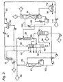
- FIG. 3 depicts a variation of the process flow diagram of FIG. 2, designed for sour feed gases that are predominately H 2 S.
- feed gases are typical of the off-gas from an alkanolamine (or activated potassium carbonate) absorber/stripper operation used to remove H 2 S and other acid gases from a process gas stream, although the H 2 S-rich feed gas may be from other sources as well.
- the feed gas may also contain CO2, hydrocarbons, mercaptans, COS, etc., but the fraction of H 2 S will typically exceed 50% and can approach 100%. All components and flows in this example are the same as in the corresponding parts of FIG. 2, except for the solvent stripper 81, which in this process serves only to separate the water and dissolved H 2 S in the solvent leaving the gas-liquid-liquid separator 26.
- the absorber/stripper referred to in the preceding paragraph is not shown in FIG. 3, but is of conventional construction and operation.
- the amine solvent used in the absorber portion of the absorber/stripper is preferably an aqueous solution of an alkanolamine, a dialkanolamine, or an alkali metal carbonate.
- Preferred among the alkanolamines and dialkanolamines are (C 1 -C 4 alkanol)-amines and di-(C 1 -C 4 alkanol)-amines, examples of which are monoethanolamine, diethanolamine, methyldiethanolamine, diglycolamine, propanolamine and isopropanolamine.
- Preferred among the alkali metal carbonates is potassium carbonate.
- the H 2 S is then stripped from the solvent by conventional means.
- the H 2 S-rich feed stream 82 enters the continuous-flow absorber/reactor 25 (corresponding to Stage 1 of FIG. 1 ) where it is contacted in cocurrent flow with a solution of SO 2 84 which contains a homogeneous catalyst for the liquid-phase Claus reaction between H 2 S and SO 2 .
- the pressure in the absorber/reactor 25 is maintained at 1.5 to 2 atmospheres absolute. Any dissolved SO 2 that is desorbed at the reactor inlet will be reabsorbed as the reaction progresses.
- the contact time in the absorber/reactor 25 is controlled to achieve complete or substantially complete reaction of the SO 2 in the solution.
- the stream leaving the bottom 85 of the absorber/reactor 25 is a combination of gas and liquid phases which are separated in the gas-liquid-liquid separator 26.
- the gas phase flows through a packed section 86 at the top of the separator and is washed with water 87 to remove solvent vapor.
- the gas 88 leaving the vapor-wash section is cooled 89 as needed to condense water 90, and the uncondensed gas 91 flows to the furnace 54 .
- the lower of the two liquid phases 92 is liquid sulfur, which is decanted from the lighter liquid solvent phase 93 .
- the wet solvent 101 emerging from the gas-liquid-liquid separator 26 is fed directly to the solvent stripper 81 where the H 2 S and most of the water are removed from the solvent.
- the solvent 102 leaving the stripper 81 is then cooled 103 and directed to the absorber 35. Since the SO 2 content of the solvent at this point is virtually zero, the solvent is a very effective sorbent for SO 2 in the absorber 35.
- the furnace 54 operates with slightly more than stoichiometric air 111 to generate the SO 2 that is then absorbed by the lean solvent 102 in the SO 2 absorber 35 while avoiding SO 3 formation.
- Sulfur-containing compounds such as COS, mercaptans and others are also burned in the furnace 54 to recover their sulfur content (as SO 2 ) and heating value with no risk of discharging such compounds to the atmosphere.
- the furnace 54 typically generates an exhaust gas containing 10% to 20% SO 2 by volume. This gas is cooled to about 150°C in a waste-heat boiler 112 and fed to the SO 2 absorber 35.
- the SO 2 solution 113 leaving the absorber is heated and returned to the absorber/reactor 35.
- a characteristic of this process is that the steam required to recover the water from the wet solvent entering the stripper exceeds that produced in the waste-heat boiler.
- FIG. 4 A further variation is shown in FIG. 4.
- the H 2 S-rich feed stream 171 enters the continuous-flow absorber/reactor 172 (corresponding to Stage 1 of FIG. 1 ) where it is contacted in cocurrent flow with a solution of SO 2 173 which contains a homogeneous catalyst for the liquid-phase Claus reaction between H 2 S and SO 2 , at a pressure of 1.5 to 2 atmospheres absolute.
- the contact time in the absorber/reactor is sufficient to achieve complete or substantially complete reaction of the SO 2 .
- the stream leaving the bottom 174 of the absorber/reactor 172 contains both gas and liquid phases which are separated in a gas-liquid-liquid separator 175.
- the gas phase flows through a packed section 176 at the top of the separator and is washed with water 177 to remove solvent vapor.
- the gas 178 leaving the vapor-wash (packed bed) section is cooled 179 as needed to condense water, which is separated from the uncondensed gas in a gas-liquid separator 181 and circulated back to the packed bed section 176 .
- the uncondensed gas 182 flows to the furnace and waste heat boiler 183.
- liquid sulfur 185 forms the lower of two liquid phases and is decanted from the solvent 184 which forms the upper of the two liquid phases.
- the solvent 184 phase is fed directly to the solvent stripper 191 where the H 2 S dissolved in the solvent is stripped with steam 190 and removed as overhead 192 .
- the solvent 193 drawn from the bottom of the stripper flows to a vacuum crystallizer 194 , where much of the remaining water is flashed to cool the solvent to the temperature required to operate the SO 2 absorber 195 (35°C to 45°C), which is essentially the same as the corresponding unit of the process flow diagram of FIG. 2.
- the residue slurry in the crystallizer is pumped to a surge tank 196 where sulfur crystals that are formed in the crystallizer are permitted to settle to form a more concentrated slurry 197 that is pumped back to the gas-liquid-liquid separator 175 .
- the crystals in the concentrated slurry melt and join the liquid sulfur product.
- Clarified solvent 198 that is lean relative to both H 2 S and SO 2 is drawn from the surge tank 196 and passed to the SO 2 absorber 195.
- This process configuration requires only about 20% of the steam output of the waste-heat boiler for its operation.
- the process configuration of FIG. 5 presents yet another example.
- the basic elements of the invention are present as a packed reactor column 201 corresponding to Stage 1 of FIG. 1 , a furnace and waste-heat boiler 202 corresponding to Stage 2, and a SO 2 absorber 203 corresponding to Stage 3.
- Both the incoming H 2 S-rich stream 204 to the reactor column 201 and the incoming SO 2 -rich stream 205 are in the gas phase.
- the two streams are mixed with an organic solvent 206 that contains a dissolved homogeneous catalyst, and the Claus reaction is conducted in the liquid phase in cocurrent flow of both gases and liquids.
- the reactor column 201 contains packing that is divided into sections 207, 208, 209, 210, 211 , with each packed section providing intense mixing of the gas and liquid phases. Cooling is performed between each adjacent pair of sections by injection of water 212 that evaporates in the column. Other means of cooling, such as various methods of indirect heat exchange, can be substituted for the water.
- the product mixture 213 which contains both gas and liquid flows into a gas-liquid-liquid separator 214 where the gas and the two liquid phases (solvent 206 and liquid sulfur 215 ) are separated, as in the process configurations of the preceding figures.
- the solvent 206 is recycled to the reactor inlet.
- FIG. 5 process configuration
- FIG. 6 process configuration of FIG. 6
- the description of these components that appears in the following discussion of FIG. 6 applies to both FIGS. 5 and 6 .
- the cocurrent flow column 201 of FIG. 5 is replaced by a countercurrent flow column 221 in the process configuration of FIG. 6.
- This countercurrent flow column 221 contains bubble-cap trays 222 , which allows the residence time of the gas and the liquids to be independently controlled. The individual trays also permit the depths of the liquid sulfur and the solvent to be set independently.
- Countercurrent flow is achieved by introducing the H 2 S-rich gas 223 and the gaseous SO 2 224 at the bottom of the column 221 for upward flow while the organic solvent 225 with dissolved catalyst is introduced at the top for downward gravity flow.
- a portion 227 amounting to up to 30% of the incoming total 226 is drawn off to bypass the reactor column 221 and to flow directly to the furnace 228.
- the flows of the H 2 S-rich gas 223 and the SO 2 -containing gas 224 are controlled so that about 80% to 90% of the H 2 S and all, or virtually all, of the SO 2 react in the column.
- a high concentration of H 2 S in the gas phase should be maintained as the reaction proceeds.
- the relative feed rates of H 2 S and SO 2 in the gas feeds to the column are preferably selected to result in a relatively large excess of H 2 S entering the column.
- the H 2 S-rich gas feed is nearly pure H 2 S, a relatively small H 2 S excess will suffice to maintain the reaction rate.
- the SO 2 stream 224 is introduced to the column 221 at a point below the inlet for the H 2 S-rich gas 223. Even if only part of the SO 2 stream is introduced at this point, this causes the liquid sulfur 229 produced in the column to contact an SO 2 -rich solution before leaving the column. This removes any undissolved H 2 S from the liquid sulfur, a favorable result since H 2 S has significant solubility in liquid sulfur and is toxic and hence an undesirable impurity.
- a small flow of stripping steam 230 may be introduced below the SO 2 inlet to strip SO 2 from both the sulfur 229 and the solvent 225.
- the reaction occurring in the column 221 is a liquid-phase reaction between H 2 S and SO 2 , both being absorbed from the gas phase by the circulating solvent 225 and introduced at relative rates to place H 2 S at a stoichiometric excess.
- H 2 S and SO 2 have similar solubilities in glycols and glycol ethers.
- the use of excess H 2 S facilitates the substantially complete reaction of SO 2 by maintaining a relatively high concentration of H 2 S concentration in the solvent.
- the vapor stream 241 leaving the column 221 consists primarily of water and unreacted H 2 S together with other components that were present in the original H 2 S feed 226.
- the vapor 241 is cooled 242, and the condensed water 245 is separated from the noncondensibles 244 in a gas-liquid separator 243 .
- the noncondensibles 244 are sent to the furnace 228, and part of the condensate 245 is returned to the reactor column 221 as a coolant.
- An additional source of coolant although not shown in the drawing, is water condensed from the SO 2 -rich stream 246 leaving the SO 2 stripper 247.
- the remainder 248 of the condensate 245 from the reactor vapor stream is saturated with H 2 S.
- This portion of the condensate is sent to a sour water stripper 249 to remove the H 2 S.
- Part of the bottoms product 250 of the sour water stripper may be used for wash water 251 at the top of the SO 2 stripper and at the top 253 of the SO 2 absorber 254.
- the noncondensibles 244 leaving the gas-liquid seperator 243 are combined with the portion 227 of the H 2 S-rich gas feed that has bypassed the reactor column, and the combined stream flows to the furnace 228 where it is burned with air.
- the quantity of air used in the furnace is preferably slightly more than the stoichiometric proportion required for complete combustion of the H 2 S, hydrocarbons and other combustibles. The amount of excess air is kept low enough however to avoid SO 3 formation.
- the furnace 228 typically generates an exhaust gas containing SO 2 in an amount of 10% by volume or more. This gas will be cooled in the waste heat boiler 255 and then fed to the SO 2 absorber 254.
- the soot which results from the partial combustion of organic compounds in a fuel-rich mixture in the furnace, enters the gas-phase Claus reactor and fouls the solid-phase catalyst (as well as the sulfur product). This is avoided in this invention by conducting the Claus reaction in the liquid phase upstream of the furnace.
- the process depicted in FIG. 6 offers the further advantage of permitting the use of one solvent in the absorber 254 and stripper 247 and another solvent in the reactor column 221 .
- the two solvents can thus be chosen independently, each selected as the one best suited for the particular function that it serves in the individual units.
- All units and unit operations including strippers, absorbers, packed columns, separators, heat exchangers, and associated pumps and valves are of conventional construction from conventional materials whose choice will be readily apparent to the skilled chemical process engineer, particularly one with skill in the treatment of sour gas streams.
Landscapes
- Chemical & Material Sciences (AREA)
- Engineering & Computer Science (AREA)
- Environmental & Geological Engineering (AREA)
- Organic Chemistry (AREA)
- Biomedical Technology (AREA)
- Health & Medical Sciences (AREA)
- Inorganic Chemistry (AREA)
- Analytical Chemistry (AREA)
- General Chemical & Material Sciences (AREA)
- Oil, Petroleum & Natural Gas (AREA)
- Chemical Kinetics & Catalysis (AREA)
- Treating Waste Gases (AREA)
- Industrial Gases (AREA)
Claims (15)
- Verfahren zur Behandlung eines H2S-enthaltenden Stromes, um darin H2S zu elementarem Schwefel umzuwandeln, wobei das Verfahren folgendes umfaßt:(a) Zuführen des H2S-enthaltenden Stromes zu einem Dauerzufluß-Reaktor und in Berührung bringen des H2S-enthaltenden Stromes in diesem Reaktor mit einem SO2-enthaltenden Strom und mit einem flüssigen organischen Lösungsmittel unter den nachfolgenden Bedingungen:(i) das flüssige organische Lösungsmittel enthält einen homogenen Katalysator, der die Flüssig-Phasenreaktion(ii) die Temperatur in dem Reaktor wird oberhalb des Schmelzpunktes von Schwefel und unterhalb des Siedepunktes des Lösungsmittels gehalten und(iii) die H2S-enthaltenden und SO2-enthaltenden Ströme werden in relativen Zufuhrgeschwindigkeiten derartig zugeführt, daß H2S im Überschuß bezüglich SO2 gemäß Reaktion (I) zugeführt wird,
um im wesentlichen das gesamte SO2 zu flüssigem elementarem Schwefel umzuwandeln und um einen Reaktoraustrag zu erzeugen, der den flüssigen elementaren Schwefel und nicht umgesetztes H2S enthält,(iv) wobei sowohl der H2S-enthaltende Strom als auch der SO2-enthaltende Strom Gasströme sind und beide in dem Reaktor durch das Lösungsmittel absorbiert werden, wobei das Lösungsmittel den Katalysator darin gelöst enthält;(b) Verbrennen des nicht umgesetzten H2S mit einem O2 enthaltenden Gas gemäß der Reaktion(c) Durchleiten des Brenngases durch einen SO2 Absorber, um im wesentlichen das gesamte SO2 aus dem Brenngas wieder zu gewinnen, wodurch ein Endgas zurückbleibt, das im wesentlichen frei von H2S und SO2 ist und wieder in den Kreislauf Zurückführen des gesamten so gewonnenen SO2 zu dem Dauerzufluß-Reaktor, wie die gesamte SO2-Zufuhr zu diesem. - Verfahren nach Anspruch 1, bei dem die Temperatur in (a) (ii) zwischen 119°C und 155°C gehalten wird.
- Verfahren nach Anspruch 1, bei dem die Temperatur in (a) (ii) zwischen 125°C und 145°C gehalten wird.
- Verfahren nach Anspruch 1, bei dem der Reaktor ein Gas-Flüssigkeits-Kontaktor vom Säulentyp ist, und in dem die Gasströme mit dem Lösungsmittel und mit dem flüssigen elementaren Schwefel im Gleichstrom fließen.
- Verfahren nach Anspruch 1, in dem der Reaktor ein Gas-Flüssigkeits-Kontaktor vom Säulentyp ist, und bei dem die Gasströme mit dem Lösungsmittel und dem flüssigen elementaren Schwefel im Gegenstrom fließen.
- Verfahren nach Anspruch 1, das weiterhin folgendes umfasst:(d) Durchleiten des Reaktoraustrags durch einen Separator, um eine flüssige Schwefelphase, eine flüssige organische Phase und eine Gasphase in getrennte Ströme aufzuteilen; und(e) wieder in den Kreislauf Zurückführen der flüssigen organischen Phase zum Einlass des Reaktors.
- Verfahren nach Anspruch 1, das weiterhin eine Zuführung eines zusätzlichen H2S-haltigen Gasstrom zu Schritt (b) umfaßt, der nicht durch den Dauerzufluß-Reaktor von Schritt (a) hindurchgeleitet wurde, in Kombination mit dem nicht umgesetzten H2S vom Reaktoraustrag, wobei das H2S in diesem zusätzlichen H2S-haltigen Gasstrom sich auf ungefähr 10% bis ungefähr 30% des dem Prozeß zugeführten Gesamt-H2S beläuft, wobei das Gesamt-H2S ungefähr 50% im Überschuß bezüglich SO2 beträgt, das dem Dauerzufluß-Reaktor gemäß Reaktion (I) zugeführt wird.
- Verfahren nach Anspruch 5, das weiterhin das Einführen des SO2-haltigen Stromes in den Gas-Flüssigkeits-Kontaktor vom Säulentyp an einem Ort unterhalb des Ortes der Einführung des H2S-haltigen Stromes umfasst, beide zum nach oben gerichteten Fluß in Gegenströmung zu den nach unten strömenden Flüssigkeiten, um gelöstes H2S aus dem flüssigen elementaren Schwefel vor dem Abziehen des flüssigen elementaren Schwefels aus dem Kontaktor zu entfernen.
- Verfahren nach Anspruch 1, bei dem das Lösungsmittel aus der Gruppe ausgewählt ist, die aus Ethern von Ethylenglykol, Diethylenglykol, Triethylenglykol, Tetraethylenglykol, Propylenglykol, Dipropylenglykol, Tripropylenglykol und Tetrapropylenglykol ausgewählt ist.
- Verfahren nach Anspruch 1, bei dem das Lösungsmittel ein Bestandteil ist, der aus der Gruppe ausgewählt ist, die aus Monomethyl-, Dimethyl-, Monoethyl- und Diethylethern von Ethylenglykol, Diethylenglykol, Triethylenglykol, Tetraethylenglykol, Propylenglykol, Dipropylenglykol, Tripropylenglykol und Tetrapropylenglykol besteht.
- Verfahren nach Anspruch 1, bei dem das Lösungsmittel ein Bestandteil ist, der aus der Gruppe ausgewählt ist, die aus Monomethyl- und Dimethylethern von Diethylenglykol, Triethylenglykol, Propylenglykol, Dipropylenglykol und Tripropylenglykol besteht.
- Verfahren nach Anspruch 1, bei dem der homogene Katalysator ein Bestandteil ist, der aus der Gruppe ausgewählt ist, die aus Pyridin und Isochinolin besteht, das wahlweise an einen oder mehreren anderen Stellen als den Kohlenstoffatomen, die dem Ring-Stickstoff benachbart sind, mit einer polaren Gruppe substituiert ist, die ein aus der Gruppe ausgewählter Bestandteil ist, die aus Hydroxyl, Hydroxyalkyl, Acetamido, A-cetamidoalkyl, Acetyl, Acetylalkyl, Acetyloxy, Acetyloxyalkyl, Alkoxy, Alkoxyalkyl, Amino, Alkylamino und Aminoalkyl besteht.
- Verfahren nach Anspruch 1, bei dem der homogene Katalysator ein Bestandteil ist, ausgewählt aus der Gruppe, die aus Pyridin und Isochinolin besteht, die an einer anderen Stelle als dem Kohlenstoffatom, das dem Ring-Stickstoff benachbart ist, mit einem Bestandteil substituiert sind, der aus der Gruppe ausgewählt ist, die aus Hydroxyl, Hydroxymethyl, Acetamido, Acetamidomethyl, Acetyl, Acetylmethyl, Acetyloxy und Acetyloxymethyl besteht.
- Verfahren nach Anspruch 1, bei dem der homogene Katalysator Pyridin ist, das an einer anderen Stelle als einem Kohlenstoffatom, das dem Ring-Stickstoff benachbart ist, mit einem Bestandteil substituiert ist, der aus der Gruppe bestehend aus Hydroxymethyl, Acetamido, Acetamidomethyl, Acetyl, Acetylmethyl, Acetyloxy und Acetyloxymethyl ausgewählt ist.
- Verfahren nach Anspruch 1, bei dem der homogene Katalysator 3-(Hydroxymethyl)pyridin ist.
Applications Claiming Priority (3)
| Application Number | Priority Date | Filing Date | Title |
|---|---|---|---|
| US08/926,652 US5928620A (en) | 1997-09-10 | 1997-09-10 | Process employing single-stage reactor for recovering sulfur from H2 S- |
| US926652 | 1997-09-10 | ||
| PCT/US1998/018400 WO1999012849A1 (en) | 1997-09-10 | 1998-09-03 | High efficiency process for recovering sulfur from h2s-bearing gas |
Publications (2)
| Publication Number | Publication Date |
|---|---|
| EP1021372A1 EP1021372A1 (de) | 2000-07-26 |
| EP1021372B1 true EP1021372B1 (de) | 2002-06-05 |
Family
ID=25453511
Family Applications (1)
| Application Number | Title | Priority Date | Filing Date |
|---|---|---|---|
| EP98945885A Expired - Lifetime EP1021372B1 (de) | 1997-09-10 | 1998-09-03 | Verfahren zur rückgewinnung von schwefel aus h2s enthaltenden gasen |
Country Status (10)
| Country | Link |
|---|---|
| US (2) | US5928620A (de) |
| EP (1) | EP1021372B1 (de) |
| JP (1) | JP3448030B2 (de) |
| AT (1) | ATE218507T1 (de) |
| AU (1) | AU9302998A (de) |
| CA (1) | CA2302673C (de) |
| DE (1) | DE69805828T2 (de) |
| EA (1) | EA002241B1 (de) |
| ES (1) | ES2178258T3 (de) |
| WO (1) | WO1999012849A1 (de) |
Families Citing this family (22)
| Publication number | Priority date | Publication date | Assignee | Title |
|---|---|---|---|---|
| US5928620A (en) * | 1997-09-10 | 1999-07-27 | The Regents Of The University Of California | Process employing single-stage reactor for recovering sulfur from H2 S- |
| US6416729B1 (en) | 1999-02-17 | 2002-07-09 | Crystatech, Inc. | Process for removing hydrogen sulfide from gas streams which include or are supplemented with sulfur dioxide |
| US6645459B2 (en) | 2001-10-30 | 2003-11-11 | The Regents Of The University Of California | Method of recovering sulfurous components in a sulfur-recovery process |
| US20030103884A1 (en) * | 2001-11-30 | 2003-06-05 | The Regents Of The University Of California | Low-emission method of recovering sulfur from sour industrial gases |
| GB0204224D0 (en) * | 2002-02-22 | 2002-04-10 | Boc Group Plc | Partial oxidation of hydrogen sulphide |
| WO2006016979A1 (en) * | 2004-07-12 | 2006-02-16 | Exxonmobil Upstream Research Company | Methods for removing sulfur-containing compounds |
| US7381393B2 (en) * | 2004-10-07 | 2008-06-03 | The Regents Of The University Of California | Process for sulfur removal suitable for treating high-pressure gas streams |
| EP1690827A1 (de) * | 2005-02-11 | 2006-08-16 | Nederlandse Organisatie voor toegepast-natuurwetenschappelijk Onderzoek TNO | Verfahren und Vorrichtung zur Rückgewinnung von Schwefelwasserstoffen |
| FR2882942B1 (fr) * | 2005-03-09 | 2007-06-15 | Inst Francais Du Petrole | Procede perfectionne de traitement d'un gaz contenant de l'hydrogene sulfure et du dioxyde de soufre |
| US7282193B2 (en) * | 2005-06-20 | 2007-10-16 | Black & Veatch Corporation | Method for energy recovery from hydrogen sulfide |
| US7831742B2 (en) * | 2007-08-10 | 2010-11-09 | Qimonda Ag | Method and device for enumeration |
| US7708801B2 (en) * | 2007-11-09 | 2010-05-04 | General Electric Company | System and methods for treating transient process gas |
| WO2010060970A1 (en) * | 2008-11-28 | 2010-06-03 | Shell Internationale Research Maatschappij B.V. | Process for the selective oxidation of hydrogen sulphide |
| US7811544B1 (en) | 2009-08-26 | 2010-10-12 | Gas Technology Institute | Sulfur recovery process |
| AU2011297370B2 (en) * | 2010-09-02 | 2014-07-03 | Mitsubishi Heavy Industries, Ltd. | Reclaiming apparatus and reclaiming method |
| US8241603B1 (en) | 2011-03-22 | 2012-08-14 | Gas Technology Institute | Process and system for removing sulfur from sulfur-containing gaseous streams |
| US9023310B1 (en) | 2014-04-25 | 2015-05-05 | Gas Technology Institute | Aqueous process for recovering sulfur from hydrogen sulfide-bearing gas |
| US9724639B2 (en) | 2015-08-18 | 2017-08-08 | United Arab Emirates University | System for contacting gases and liquids |
| US10118843B2 (en) | 2015-08-18 | 2018-11-06 | United Arab Emirates University | Process for capture of carbon dioxide and desalination |
| GB2567095B (en) | 2016-07-05 | 2023-05-10 | Ineos Americas Llc | Method and for recovering absorbing agents in acid gas treatment |
| US11731080B2 (en) | 2018-12-21 | 2023-08-22 | King Fahd University Of Petroleum And Minerals | Method of sweetening hydrocarbon gas from hydrogen sulfide |
| CN113860308B (zh) * | 2021-09-15 | 2023-01-10 | 爱斯特(成都)生物制药股份有限公司 | 一种使用二氧化硫连续制备硫光气的方法 |
Family Cites Families (11)
| Publication number | Priority date | Publication date | Assignee | Title |
|---|---|---|---|---|
| JPS5116186B2 (de) * | 1972-12-15 | 1976-05-22 | ||
| US4124685A (en) * | 1976-06-08 | 1978-11-07 | Tarhan Mehmet O | Method for substantially complete removal of hydrogen sulfide from sulfur bearing industrial gases |
| FR2532292A2 (fr) * | 1982-08-25 | 1984-03-02 | Raffinage Cie Francaise | Procede d'elimination de l'hydrogene sulfure contenu dans un melange gazeux |
| CA1219731A (en) * | 1983-05-02 | 1987-03-31 | John Happel | Process for desulfurizing fuel gases |
| DE3333933A1 (de) * | 1983-09-20 | 1985-04-04 | Linde Ag, 6200 Wiesbaden | Verfahren zum reinigen eines gasstromes |
| WO1986002628A1 (en) * | 1984-11-04 | 1986-05-09 | The Regents Of The University Of California | Process for removal of hydrogen sulfide from gases |
| US4976935A (en) * | 1984-11-04 | 1990-12-11 | Regents Of The University Of California | Regeneration of solvent in H2 S removal from gases |
| US5098681A (en) * | 1990-08-16 | 1992-03-24 | The Dow Chemical Company | Process for absorption of sulfur compounds from fluids |
| US5389351A (en) * | 1992-11-04 | 1995-02-14 | Hasebe; Nobuyasu | Method for desulfurizing a gas |
| US5397556A (en) * | 1992-12-16 | 1995-03-14 | The Regents Of The Unviversity Of California | Process for recovery of sulfur from acid gases |
| US5928620A (en) * | 1997-09-10 | 1999-07-27 | The Regents Of The University Of California | Process employing single-stage reactor for recovering sulfur from H2 S- |
-
1997
- 1997-09-10 US US08/926,652 patent/US5928620A/en not_active Expired - Lifetime
-
1998
- 1998-09-03 EP EP98945885A patent/EP1021372B1/de not_active Expired - Lifetime
- 1998-09-03 US US09/486,925 patent/US6495117B1/en not_active Expired - Lifetime
- 1998-09-03 ES ES98945885T patent/ES2178258T3/es not_active Expired - Lifetime
- 1998-09-03 WO PCT/US1998/018400 patent/WO1999012849A1/en not_active Ceased
- 1998-09-03 AU AU93029/98A patent/AU9302998A/en not_active Abandoned
- 1998-09-03 AT AT98945885T patent/ATE218507T1/de not_active IP Right Cessation
- 1998-09-03 EA EA200000301A patent/EA002241B1/ru not_active IP Right Cessation
- 1998-09-03 DE DE69805828T patent/DE69805828T2/de not_active Expired - Lifetime
- 1998-09-03 CA CA002302673A patent/CA2302673C/en not_active Expired - Fee Related
- 1998-09-03 JP JP2000510669A patent/JP3448030B2/ja not_active Expired - Fee Related
Also Published As
| Publication number | Publication date |
|---|---|
| DE69805828T2 (de) | 2003-01-02 |
| JP2001515832A (ja) | 2001-09-25 |
| JP3448030B2 (ja) | 2003-09-16 |
| EP1021372A1 (de) | 2000-07-26 |
| US5928620A (en) | 1999-07-27 |
| CA2302673C (en) | 2009-05-12 |
| CA2302673A1 (en) | 1999-03-18 |
| AU9302998A (en) | 1999-03-29 |
| EA002241B1 (ru) | 2002-02-28 |
| ES2178258T3 (es) | 2002-12-16 |
| ATE218507T1 (de) | 2002-06-15 |
| US6495117B1 (en) | 2002-12-17 |
| EA200000301A1 (ru) | 2000-12-25 |
| WO1999012849A1 (en) | 1999-03-18 |
| DE69805828D1 (de) | 2002-07-11 |
Similar Documents
| Publication | Publication Date | Title |
|---|---|---|
| US6495117B1 (en) | Process for recovering sulfur from H2S-bearing gas | |
| US12545580B2 (en) | Method for production of elemental sulfur and sulfuric acid | |
| US7662215B2 (en) | Methods for removing sulfur-containing compounds | |
| KR100810188B1 (ko) | 황화수소 함유 가스 스트림의 처리방법 | |
| US10479684B2 (en) | Enhancement of claus tail gas treatment by sulfur dioxide-selective membrane technology and sulfur dioxide-selective absorption technology | |
| US9339756B1 (en) | Claus hydrocarbon destruction via staged solvent regeneration | |
| JP4303111B2 (ja) | 硫黄回収プロセスにおける硫黄成分の回収方法 | |
| US20060078491A1 (en) | Process for sulfur removal suitable for treating high-pressure gas streams | |
| GB2079307A (en) | Selective separation of hydrogen sulphide from gaseous mixtures | |
| US4124685A (en) | Method for substantially complete removal of hydrogen sulfide from sulfur bearing industrial gases | |
| US5556606A (en) | Method and apparatus for controlling the hydrogen sulfide concentration in the acid gas feedstock of a sulfur recovery unit | |
| KR20020049001A (ko) | 이산화황으로부터 삼산화황, 황산 및 발연 황산의 제조 방법 | |
| JP2005507844A5 (de) | ||
| GB2118455A (en) | Selective acid gas removal | |
| US3953586A (en) | Process for purifying gases containing H2 S | |
| US20030103884A1 (en) | Low-emission method of recovering sulfur from sour industrial gases | |
| US3733779A (en) | Stripping of sulfur dioxide from gas streams by use of n-alkyl lactams | |
| US20090226364A1 (en) | Process for treating acid gas in staged furnaces with inter-stage heat recovery and inter-stage sulfur production | |
| US3733780A (en) | Process for using n-alkyl lactam for stripping sulfur dioxide from gas streams and recovering liquid sulfur dioxide | |
| US3733781A (en) | Recovery of n-alkyl lactams employed in stripping of sulfur dioxide from gas streams | |
| MXPA00002441A (en) | High efficiency process for recovering sulfur from h2 | |
| RU2824360C2 (ru) | Способ получения элементарной серы и серной кислоты | |
| JP3851681B2 (ja) | 天然ガスからの硫黄回収方法 |
Legal Events
| Date | Code | Title | Description |
|---|---|---|---|
| PUAI | Public reference made under article 153(3) epc to a published international application that has entered the european phase |
Free format text: ORIGINAL CODE: 0009012 |
|
| 17P | Request for examination filed |
Effective date: 20000407 |
|
| AK | Designated contracting states |
Kind code of ref document: A1 Designated state(s): AT BE CH CY DE DK ES FI FR GB GR IE IT LI LU MC NL PT SE |
|
| AX | Request for extension of the european patent |
Free format text: AL PAYMENT 20000411;LT PAYMENT 20000411;LV PAYMENT 20000411;RO PAYMENT 20000411;SI PAYMENT 20000411 |
|
| 17Q | First examination report despatched |
Effective date: 20000912 |
|
| RTI1 | Title (correction) |
Free format text: HIGH EFFICIENCY PROCESS FOR RECOVERING SULFUR FROM H2S-BEARING GAS |
|
| RTI1 | Title (correction) |
Free format text: HIGH EFFICIENCY PROCESS FOR RECOVERING SULFUR FROM H2S-BEARING GAS |
|
| GRAG | Despatch of communication of intention to grant |
Free format text: ORIGINAL CODE: EPIDOS AGRA |
|
| RTI1 | Title (correction) |
Free format text: HIGH EFFICIENCY PROCESS FOR RECOVERING SULFUR FROM H2S-BEARING GAS |
|
| GRAG | Despatch of communication of intention to grant |
Free format text: ORIGINAL CODE: EPIDOS AGRA |
|
| GRAG | Despatch of communication of intention to grant |
Free format text: ORIGINAL CODE: EPIDOS AGRA |
|
| GRAH | Despatch of communication of intention to grant a patent |
Free format text: ORIGINAL CODE: EPIDOS IGRA |
|
| GRAH | Despatch of communication of intention to grant a patent |
Free format text: ORIGINAL CODE: EPIDOS IGRA |
|
| GRAA | (expected) grant |
Free format text: ORIGINAL CODE: 0009210 |
|
| AK | Designated contracting states |
Kind code of ref document: B1 Designated state(s): AT BE CH CY DE DK ES FI FR GB GR IE IT LI LU MC NL PT SE |
|
| AX | Request for extension of the european patent |
Free format text: AL PAYMENT 20000411;LT PAYMENT 20000411;LV PAYMENT 20000411;RO PAYMENT 20000411;SI PAYMENT 20000411 |
|
| LTIE | Lt: invalidation of european patent or patent extension | ||
| PG25 | Lapsed in a contracting state [announced via postgrant information from national office to epo] |
Ref country code: LI Free format text: LAPSE BECAUSE OF FAILURE TO SUBMIT A TRANSLATION OF THE DESCRIPTION OR TO PAY THE FEE WITHIN THE PRESCRIBED TIME-LIMIT Effective date: 20020605 Ref country code: GR Free format text: LAPSE BECAUSE OF FAILURE TO SUBMIT A TRANSLATION OF THE DESCRIPTION OR TO PAY THE FEE WITHIN THE PRESCRIBED TIME-LIMIT Effective date: 20020605 Ref country code: FI Free format text: LAPSE BECAUSE OF FAILURE TO SUBMIT A TRANSLATION OF THE DESCRIPTION OR TO PAY THE FEE WITHIN THE PRESCRIBED TIME-LIMIT Effective date: 20020605 Ref country code: CH Free format text: LAPSE BECAUSE OF FAILURE TO SUBMIT A TRANSLATION OF THE DESCRIPTION OR TO PAY THE FEE WITHIN THE PRESCRIBED TIME-LIMIT Effective date: 20020605 Ref country code: AT Free format text: LAPSE BECAUSE OF FAILURE TO SUBMIT A TRANSLATION OF THE DESCRIPTION OR TO PAY THE FEE WITHIN THE PRESCRIBED TIME-LIMIT Effective date: 20020605 |
|
| REF | Corresponds to: |
Ref document number: 218507 Country of ref document: AT Date of ref document: 20020615 Kind code of ref document: T |
|
| REG | Reference to a national code |
Ref country code: GB Ref legal event code: FG4D |
|
| REG | Reference to a national code |
Ref country code: CH Ref legal event code: EP |
|
| REG | Reference to a national code |
Ref country code: IE Ref legal event code: FG4D |
|
| REF | Corresponds to: |
Ref document number: 69805828 Country of ref document: DE Date of ref document: 20020711 |
|
| PG25 | Lapsed in a contracting state [announced via postgrant information from national office to epo] |
Ref country code: LU Free format text: LAPSE BECAUSE OF NON-PAYMENT OF DUE FEES Effective date: 20020903 Ref country code: IE Free format text: LAPSE BECAUSE OF NON-PAYMENT OF DUE FEES Effective date: 20020903 |
|
| PG25 | Lapsed in a contracting state [announced via postgrant information from national office to epo] |
Ref country code: SE Free format text: LAPSE BECAUSE OF FAILURE TO SUBMIT A TRANSLATION OF THE DESCRIPTION OR TO PAY THE FEE WITHIN THE PRESCRIBED TIME-LIMIT Effective date: 20020905 Ref country code: PT Free format text: LAPSE BECAUSE OF FAILURE TO SUBMIT A TRANSLATION OF THE DESCRIPTION OR TO PAY THE FEE WITHIN THE PRESCRIBED TIME-LIMIT Effective date: 20020905 Ref country code: DK Free format text: LAPSE BECAUSE OF FAILURE TO SUBMIT A TRANSLATION OF THE DESCRIPTION OR TO PAY THE FEE WITHIN THE PRESCRIBED TIME-LIMIT Effective date: 20020905 |
|
| ET | Fr: translation filed | ||
| PG25 | Lapsed in a contracting state [announced via postgrant information from national office to epo] |
Ref country code: CY Free format text: LAPSE BECAUSE OF FAILURE TO SUBMIT A TRANSLATION OF THE DESCRIPTION OR TO PAY THE FEE WITHIN THE PRESCRIBED TIME-LIMIT Effective date: 20020930 |
|
| REG | Reference to a national code |
Ref country code: CH Ref legal event code: PL |
|
| REG | Reference to a national code |
Ref country code: ES Ref legal event code: FG2A Ref document number: 2178258 Country of ref document: ES Kind code of ref document: T3 |
|
| PG25 | Lapsed in a contracting state [announced via postgrant information from national office to epo] |
Ref country code: MC Free format text: LAPSE BECAUSE OF NON-PAYMENT OF DUE FEES Effective date: 20030401 |
|
| PLBE | No opposition filed within time limit |
Free format text: ORIGINAL CODE: 0009261 |
|
| STAA | Information on the status of an ep patent application or granted ep patent |
Free format text: STATUS: NO OPPOSITION FILED WITHIN TIME LIMIT |
|
| 26N | No opposition filed |
Effective date: 20030306 |
|
| REG | Reference to a national code |
Ref country code: IE Ref legal event code: MM4A |
|
| REG | Reference to a national code |
Ref country code: FR Ref legal event code: PLFP Year of fee payment: 18 |
|
| PGFP | Annual fee paid to national office [announced via postgrant information from national office to epo] |
Ref country code: ES Payment date: 20150928 Year of fee payment: 18 Ref country code: GB Payment date: 20150928 Year of fee payment: 18 |
|
| PGFP | Annual fee paid to national office [announced via postgrant information from national office to epo] |
Ref country code: FR Payment date: 20150917 Year of fee payment: 18 Ref country code: BE Payment date: 20150928 Year of fee payment: 18 |
|
| PGFP | Annual fee paid to national office [announced via postgrant information from national office to epo] |
Ref country code: IT Payment date: 20150923 Year of fee payment: 18 |
|
| PGFP | Annual fee paid to national office [announced via postgrant information from national office to epo] |
Ref country code: DE Payment date: 20150929 Year of fee payment: 18 |
|
| PGFP | Annual fee paid to national office [announced via postgrant information from national office to epo] |
Ref country code: NL Payment date: 20150926 Year of fee payment: 18 |
|
| PG25 | Lapsed in a contracting state [announced via postgrant information from national office to epo] |
Ref country code: BE Free format text: LAPSE BECAUSE OF NON-PAYMENT OF DUE FEES Effective date: 20160930 |
|
| REG | Reference to a national code |
Ref country code: DE Ref legal event code: R119 Ref document number: 69805828 Country of ref document: DE |
|
| REG | Reference to a national code |
Ref country code: NL Ref legal event code: MM Effective date: 20161001 |
|
| GBPC | Gb: european patent ceased through non-payment of renewal fee |
Effective date: 20160903 |
|
| PG25 | Lapsed in a contracting state [announced via postgrant information from national office to epo] |
Ref country code: NL Free format text: LAPSE BECAUSE OF NON-PAYMENT OF DUE FEES Effective date: 20161001 |
|
| REG | Reference to a national code |
Ref country code: FR Ref legal event code: ST Effective date: 20170531 |
|
| PG25 | Lapsed in a contracting state [announced via postgrant information from national office to epo] |
Ref country code: DE Free format text: LAPSE BECAUSE OF NON-PAYMENT OF DUE FEES Effective date: 20170401 Ref country code: FR Free format text: LAPSE BECAUSE OF NON-PAYMENT OF DUE FEES Effective date: 20160930 Ref country code: GB Free format text: LAPSE BECAUSE OF NON-PAYMENT OF DUE FEES Effective date: 20160903 |
|
| PG25 | Lapsed in a contracting state [announced via postgrant information from national office to epo] |
Ref country code: IT Free format text: LAPSE BECAUSE OF NON-PAYMENT OF DUE FEES Effective date: 20160903 |
|
| REG | Reference to a national code |
Ref country code: BE Ref legal event code: MM Effective date: 20160930 |
|
| REG | Reference to a national code |
Ref country code: ES Ref legal event code: FD2A Effective date: 20180507 |
|
| PG25 | Lapsed in a contracting state [announced via postgrant information from national office to epo] |
Ref country code: ES Free format text: LAPSE BECAUSE OF NON-PAYMENT OF DUE FEES Effective date: 20160904 |