EP1021053A2 - Verfahren und Anordnung für die gleichzeitige Benützung von Datenübertragungskanälen - Google Patents
Verfahren und Anordnung für die gleichzeitige Benützung von Datenübertragungskanälen Download PDFInfo
- Publication number
- EP1021053A2 EP1021053A2 EP00660003A EP00660003A EP1021053A2 EP 1021053 A2 EP1021053 A2 EP 1021053A2 EP 00660003 A EP00660003 A EP 00660003A EP 00660003 A EP00660003 A EP 00660003A EP 1021053 A2 EP1021053 A2 EP 1021053A2
- Authority
- EP
- European Patent Office
- Prior art keywords
- real time
- service components
- time service
- applications
- local
- Prior art date
- Legal status (The legal status is an assumption and is not a legal conclusion. Google has not performed a legal analysis and makes no representation as to the accuracy of the status listed.)
- Withdrawn
Links
Images


Classifications
-
- H—ELECTRICITY
- H04—ELECTRIC COMMUNICATION TECHNIQUE
- H04W—WIRELESS COMMUNICATION NETWORKS
- H04W4/00—Services specially adapted for wireless communication networks; Facilities therefor
- H04W4/12—Messaging; Mailboxes; Announcements
-
- H—ELECTRICITY
- H04—ELECTRIC COMMUNICATION TECHNIQUE
- H04W—WIRELESS COMMUNICATION NETWORKS
- H04W4/00—Services specially adapted for wireless communication networks; Facilities therefor
- H04W4/18—Information format or content conversion, e.g. adaptation by the network of the transmitted or received information for the purpose of wireless delivery to users or terminals
-
- H—ELECTRICITY
- H04—ELECTRIC COMMUNICATION TECHNIQUE
- H04W—WIRELESS COMMUNICATION NETWORKS
- H04W76/00—Connection management
- H04W76/10—Connection setup
-
- H—ELECTRICITY
- H04—ELECTRIC COMMUNICATION TECHNIQUE
- H04W—WIRELESS COMMUNICATION NETWORKS
- H04W76/00—Connection management
- H04W76/20—Manipulation of established connections
-
- H—ELECTRICITY
- H04—ELECTRIC COMMUNICATION TECHNIQUE
- H04W—WIRELESS COMMUNICATION NETWORKS
- H04W88/00—Devices specially adapted for wireless communication networks, e.g. terminals, base stations or access point devices
- H04W88/02—Terminal devices
- H04W88/06—Terminal devices adapted for operation in multiple networks or having at least two operational modes, e.g. multi-mode terminals
Definitions
- the invention concerns generally the technology of arranging data transmission between at least two terminals of a telecommunication system. Especially the invention concerns the technology of arranging for an optimally dimensioned channel solution for multimedia connections consisting of components characterised by various capacity needs.
- Multimedia in general is understood as the synchronised presentation of audiovisual objects to a human user.
- a point-to-point (or point-to-multipoint, or multipoint-to-multipoint) multimedia connection in which each user has a terminal with audiovisual capabilities and the telecommunication system connecting the terminals will communicate various kinds of audiovisual material as well as plain digital data between the terminals.
- a simple example of a portable multimedia terminal is a mobile video telephone, the user of which is able to view a video image of his conversation partner while listening him to talk. It is typical to multimedia connections that the amount of data to be transmitted may vary considerably according to which kind of imaging subsystems are used, what other data is there to be transmitted in addition to the video image, and what kind of data compression, encryption and channel coding schemes are employed.
- the recommendation number H.324 of the ITU-T calls for the multiplexing of all different data streams (audio, video and data) into a single transmission channel, which has typically a capacity of 28.8 kbps and is provided through a modem according the V.34 standard or through a transparent HSCSD (High Speed Circuit Switched Data) transceiver in the GSM system (Global System for Mobile telecommunications).
- the capacity allocated for a single multimedia connection is therefore fixed, which dictates that if the demands of one component data stream increase, the other components must surrender some capacity. Even a minor increase in the amount of simultaneously transmitted data may cause considerable degradation in the quality of e.g. video images, which will in turn cause annoyance to the communicating parties.
- the object of the present invention is to provide a method and arrangement for setting up and maintaining a multimedia connection that would allow for flexible changes in the amount of transmitted data per time unit and/or bandwidth. It is also an object of the invention to provide a method and arrangement for effectively using the resources of the radio interface between a mobile terminal and a base station for communicating information related to a multimedia connection.
- the objects of the invention are achieved by a parallel arrangement of a real time channel and a non-real time packet channel which is closely associated to the real time channel.
- the method according to the invention is characterised in that it comprises the steps of
- the invention also applies to a wireless terminal arrangement for acting as a communicating party in a multimedia connection consisting of real time service components and non-real time service components, of which the real time service components are to be utilized by local real time applications and the non-real time service components are to be utilized by local non-real time applications. It is characterised in that it comprises
- a mobile multimedia terminal will comprise parallel arrangements for the communication of real time and non-real time information.
- Real time information is most advantageously related to audio and video, real time data and/or system control applications.
- Non-real time information may relate to any data the communication of which is not time-critical. Typical examples of non-real time information is the data representing a still image, a text file, a binary file or even low-bitrate commands like far end camera control commands.
- Allowing for simultaneous activity by both parts is advantageous and can be realised for example with an HSCSD/GPRS GSM transceiver of Class A; however, a specific prioritizing arrangement may be applied if the transceiver is a HSCSD/GPRS GSM transceiver of Class B or other transceiver that only allows for one of the parts to be active at a given moment.
- the usage of the radio resources is optimized by activating the required radio bearers only according to need. Therefore the multimedia connection according to the invention will not keep any radio resources unnecessarily reserved, which helps to avoid congestion in the radio access networks and saves electric energy which is important in portable battery-driven terminals.
- a user of a wireless terminal gains the advantage in the form of reduced communication costs, because the invention will enable the (generally more expensive) real time radio bearers to be involved only when they are necessary: non-real time services may be provided through (cheaper) non-real time radio bearers.
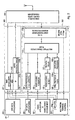
- the standard specifies four possible sources and sinks of information: video input and/or output equipment 101, audio input and/or output equipment 102, user data applications 103 and system control 104.
- Inputted video information to be transmitted is encoded and received video information to be outputted is decoded in the video codec block 105, which itself conforms to the known standards H.263 or H. 261.
- Inputted audio information to be transmitted is correspodingly encoded and received audio information to be outputted is correspodingly decoded in the audio codec block 106, which conforms to the known standard G.723.
- An optional delay block 107 provides for any necessary delay in the received audio signal to synchronize it with the received video signal.
- a rather generally defined data protocol block 108 will implement the necessary encoding and/or decoding functions for transferring the data related to the userdata applications.
- the role of the system control block 104 relates both to the operation of the terminal itself and to the realisation of any necessary end-to-end system functions.
- the terminal comprises, coupled to a first system control port, a block 109 that consists of a control protocol part 109a and a SRP/LAPM part (Simple Retransmission Protocol / Link Access Procedures for Modems) 109b.
- the former operates according to the known standard H.245 that provides end-to-end signalling for proper operation of the terminals, and signals all other end-to-end system functions. It provides for capability exchange, signalling of commands and indications, and messages to open and describe the content of logical channels.
- the SRP/LAPM part 109b is an intermediate layer in the control channel protocol stack between the H.245 layer and the multiplexing/demultiplexing block 110 and it implements either a simple retransmission protocol, where each transmitted frame must be acknowledged before the transmission of next such frame is allowed, or the LAPM protocol as defined in the known V. 42 standard.
- the multiplexing/demultiplexing block 110 performs the multiplexing function from separate video, audio, data and control streams into a single stream to be transmitted, and correspondingly the demultiplexing function from a received stream to separate video, audio, data and control streams. To those media types where applicable it also performs logical framing, sequence numbering, error detection and error correction by retransmission.
- the modem block 111 consists of a modem proper 111a and a control/sensing subblock 111b.
- the modem is basically a two-way converter for performing the necessary conversions between the digital information handled inside the terminal and the analog signal that can be transmitted over a telephone network. It operates according to the known standards V.34 or V.8/V.8bis.
- control/sensing subblock 111b is used to provide the necessary control/sensing functions of the modem/network interface according to the known standard V.25ter. It has a direct connection to a second system control port and further to the system control block 104.
- the H.324 standard sets very few requirements to the General Switched Telephone Network (GSTN) 112 that will offer the link between two terminals like that in Fig. 1. Multipoint communication is to be accomplished with the help of Multipoint Control Units (MCU) 113 connected to the telephone network.
- MCU Multipoint Control Units
- H.324 allows for a wide variety of both real time and non-real time data application to operate within the user data applications block 103.
- standardised data applications the standard mentions
- Fig. 2 illustrates an advantageous terminal according to the invention.
- a large part of it consists of blocks and connections that are similar to the corresponding blocks in Fig. 1, but their functions are partly different.
- the same reference designators are used for the similar parts.
- the terminal arrangement of Fig. 2 consists of a multimedia applications block 201, a real time channel block 202, a non-real time channel block 203 and a transceiver block 204.
- the division into blocks is functional and does not require that the functions illustrated within the same block should be implemented within a single device. Neither does the division into blocks exclude some functions illustrated in different blocks from being implemented within a single device.
- the applications block 201 comprises a NRT data block 205 which represents all such applications that source and/or sink non-real time data, and a RT data block 206 which represents all such applications that source and/or sink real time data. Together the blocks 205 and 206 can be seen to roughly correspond to the user data applications block 103 in Fig. 1. Additionally the applications block comprises a video/audio application and I/O equipment block 207 that approximately corresponds to a combination of the blocks 101 and 102 in Fig. 1, and a system control block 208 with a separate non-real time control part 208a.
- the blocks 206, 207 and 208 communicate with the real time channel block 202 so that the RT data block 206 is coupled to the data protocol block 108', the video part (not separately shown) of block 207 is coupled to the video codec block 105, the audio part (not separately shown) of block 207 is coupled to the audio codec block 106 and the system control block 208 is coupled both to the control protocol part 109a of block 109 and to the control/sensing subblock 209b of the data adapter block 209.
- the organisation and work distribution of blocks 105, 106, 107, 108', 109', 110 and 209 is similar to that of blocks 105, 106, 107, 108, 109, 110 and 111 in Fig. 1 with the exceptions that the data protocol block 108' is only arranged to implement real time data protocols, the control protocol block 109' is adapted to handle some signalling according to the invention and a data adapter block 209 according to the known standard V.110 replaces the modem block 111; replacing a modem with a data adapter signifies that the telecommunication network that is to provide the communication connection between terminals is digital and not analog. Connections associated with data flows have been shown with solid lines and connections associated with control flows are represented by broken lines.
- the NRT data block 205 does not have a connection to the data protocol block 108' and indeed not to the real time channel block 202 at all.
- a separate non-real time channel block 203 where the NRT data block 205 is coupled to both a packet protocol block 210 and a short message service or SMS block 211.
- the former of these comprises an IP (Internet Protocol) subblock 210a, a GPRS subblock 210b and a NarrowBand Socket subblock 210c.
- the transceiver 204 is capable of communicating both circuit-switched information with the data adapter 209 in the real time channel block 202 and packet-switched information with the SMS and packet protocol blocks of the non-real time channel block 203.
- the transceiver is an HSCSD/GPRS GSM transceiver of Class A, which means that it supports simultaneous GPRS and HSCSD bearers. Later we will show how the invention is applicable in connection with a transceiver that only supports one bearer type at a time.
- the service components of a multimedia connection may be divided into the real time and non-real time categories.
- the real time channel block 202 provides for a certain transmission capacity to the use of the real time service components, and the varying capacity needs of the non-real time service components are satisfied by the non-real time channel block 203.
- the use of parallel real time and non-real time arrangements guarantees that the real time service components do not have to surrender any capacity to the non-real time service components, at least as long as the transceiver supports simultaneous real time and non-real time activity.
- the data agent could redirect the non-real time data to be transmitted to the real time data channel instead of the preliminarily specified non-real time data channel.
- a simpler enhancement would be the one where the division to real time and non-real time service components is fixed, but an application preliminarily targeted for GPRS could also use SMS as a secondary alternative or vice versa.
- the system control block 208 includes the necessary functions for administering the bearer set-up and tear-down processes so that during a multimedia communication session only those bearers are maintained in active state at each moment that are necessary. If, for example, the multimedia connection is a video telephone connection with initially no associated non-real time data, the system control block would arrange for the set-up of only an HSCSD bearer. Only if there arises, in the middle of the video telephone connection, the need for transmitting a text file or some other non-real time information between the communicating parties, the system control block would arrange for the set-up of a GPRS bearer.
- system control block could arrange for an SMS message with far end camera control commands within it to be sent only after the user has indicated his will to control the far end camera; it may be that no such need arises at any phase of the video telephone connection.
- a very simple connection could be handled through GPRS and/or SMS bearers only with no need to set up an HSCSD bearer.
- a packet radio terminal may initially register to the service of a base station, meaning that a packet radio bearer is intially set up, but as long as there is no actual data to be transmitted the connection remains in an idle state where it consumes a very small amount of the radio resources or no radio resources at all. Only at the moment when the need for actual data transmission arises will the idle connection be upgraded to an active state for the duration of the actual data transmission. Thereafter it will return to the idle state to wait for either a new period of actual data transmission or a complete tear-down.
- This procedure is advantageously adopted in the invention so that a packet radio bearer is always initially set up when a terminal according to the invention is camping in a cell that can offer multimedia services, and the state of the packet radio connection is independent of the state of potential simultaneous real time connections.
- the ETSI European Telecommunications Standards Institute technical specification number GSM 02.60 Phase 2+, which is incorporated herein by reference, defines a Class B transceiver in the following way: "Supports simultaneous attach, simultaneous activation and simultaneous monitor. Supports only limited simultaneous invocation: GPRS virtual circuits (GPRS-activation) shall not be cleared down due to invocation or traffic of circuit switched services, the status of the GPRS virtual connection is then "busy or held”. Simultaneous traffic shall not be supported. The mobile user can make and/or receive calls on either of the two services sequentially but not simultaneously. The selection of the approriate service is performed automatically.” In other words, if the transceiver 204 of Fig. 2 is a Class B transceiver, it will prioritize real time services and handle non-real time services only when there is no real time activity.
- the operation of the system control block 208 may be augmented (or a completely new functional block may be added) to implement a so-called Service Prioritization Agent, if the network offers support for such an arrangement.
- the purpose of such an agent would be to arrange for the alternating use of the real time and non-real time services according to a certain Service Priority Profile, which may be either fixed or definable by the user.
- the Service Priority Profile could state for example that if there arises, during an active real time transmission, the need for transmitting a piece of non-real time data, the real time transmission shall be interrupted for the maximum duration of X milliseconds, where X is a parameter with a selectable value. Suitable forms for the Service Priority Profile may be obtained through experimenting.
- a terminal arrangement we may consider the combination of a mobile telephone and a laptop computer or other auxiliary device where applications are running on top of a multimedia protocol like H.324.
- a multimedia protocol like H.324.
- the auxiliary device will only communicate with the mobile telephone through a single multiplexed data flow which may contain both real time and non-real time components.
- a prior art arrangement would only use a real time bearer for transmitting the whole multiplexed data flow. If the requirements of the H.324 specification may be relaxed, there may be separate (non-multipexed) connections between the mobile telephone and the auxiliary device for real time and non-real time data flows.
- connection to be used is a simple point-to-point multimedia connection between two terminals like that in Fig. 2.
- Block 301 illustrates the known connection setup procedures according to the H.245 standard. It is followed by block 302 which represents a capabilities exchange.
- a certain form of capabilities exhange has been previously described in section 6.5.1 of the H.324 standard; the capabilities exchange according to the invention differs from the known procedures in that the terminals indicate to each other their capability of (simultaneously) handling real time and non-real time services by the parallel channel arrangement seen m Fig. 2.
- One suitable way for implementing such indications is the NonStandardParameter structure defined in the H.245 standard.
- a certain non-standard message may be generally associated with the meaning that it indicates the parallel real time / non-real time capability.
- the capabilities according to the invention are indicated over a non-real time channel by using packet or SMS services before the actual information exchange related to the multimedia connection will begin.
- Block 303 illustrates an active real time connection, for example a video telephone connection. Every now and then there arises, during the active real-time connection, the need for parallelly exchanging non-real time data between the terminals.
- the corresponding short passages of transferred packet data and/or short messages are indicated as the blocks 304, 305 and 306. After the deactivation of the real time connection there may still be a passage of non-real time data exchange between the terminals as illustrated by block 307. Thereafter the connection is terminated.
- the method according to Fig. 3 is easily generalised to a point-to-multipoint or multipoint-to-multipoint connection where a number of terminals have a pool of simultaneous connections. Each terminal keeps a record that describes the identity and capabilities of each other terminal taking part in the connection. In the connection set-up phase there is a round of capabilities exchanges where each terminal receives the capability information of the other terminals.
- a multipoint control unit in the network mediating the connections will arrange for the multipoint transmission channels and transmission schedules so tat every piece of transmitted information reaches its intended destination with the minimum number of collisions.
- point-to-multipoint or multipoint-to-multipoint real time connection an arbitrary number of point-to-point point-to-multipoint or multipoint-to-multipoint non-real time connections may take place. Arranging for the required connections in the network is on the responsibility of the multipoint control unit. Similarly, if the non-real time connections are the dominant form of communication in the point-to-multipoint or multipoint-to-multipoint connections, they may be augmented with an arbitrary number of point-to-point point-to-multipoint or multipoint-to-multipoint real time connections.
- Fig. 4 illustrates a telecommunication system where two terminals 401 and 402 are connected to a telecommunication network 403.
- the terminals 401 and 402 have the parallel real time / non-real dine capabilities according to the invention, and the network 403 is equipped for transmitting telephone connections through base stations (BS) 404, base station controllers (BSC) 405 and mobile switching centres (MSC) 406.
- BS base stations
- BSC base station controllers
- MSC mobile switching centres
- the network comprises at least one Packet Control Unit (PCU) 407.
- PCU Packet Control Unit
- SGSN serving GPRS support node
- a PCU may be situated in a base station or even in the SGSN.
- a trunk-line network 409 connects the serving GPRS support nodes to each other; there may also be gateway GPRS support nodes 410 through which there are connections to other packet data networks like the Internet.
- the real time connection goes from a terminal 401 Through a base station 404, a base station controller 405, a mobile switching centre 406, another base station controller 405 and another base station 404 to the other terminal 402.
- the non-real time connection goes from a terminal 401 through a base station 404, a base station controller 405, the packet control unit 407 connected to the base station controller, a serving GPRS support node 408, the trunk-line network 409, another serving GPRS support node 408, another packet control unit 407, the base station controller 405 connected to the other packet control unit and another base station 404 to the other terminal 402.
- a short message services centre 411 is also coupled to the mobile switching centre so that potential SMS messages go through it according to known SMS routines.
- the multimedia terminal contol block 208 in Fig. 2 is responsible for the initialization of the capabilities exchange signalling which is needed for informing a remote terminal about the capabilities of the present terminal and/or requesting the corresponding capabilities of the remote terminal.
- this signalling it is possible to arrange this signalling to be done in at least two different ways, i.e. through H.245 signalling or through at least one of the non-real time pipes (GPRS, SMS).
- Fig. 5 is related to the H.245 signalling alternative.
- a typical example of the H.245 control protocol module 109' adapted to the invention consists of the H.245 application programming interface (API) 502, several signalling units 503 to 512 and a simple retransmission protocol (SRP) 513.
- the H.245 control protocol module is usually called the H.245 module for brevity.
- the H.245 API 502 provides the interface for using the H.245 module 109.
- the instance that uses the H.245 module is called the user.
- the main functionality provided by the H.245 API is the sending and receiving of control information messages called primitives.
- the H.245 API 502 also provides means for setting several parameters that have an effect on the operation of H.245 module.
- the H.245 protocol contains several types of control negotiations. All the signalling done for a certain type of negotiation is called a signalling procedure.
- the entity that performs the signalling procedures of one kind is called a signalling unit (related to the term "signalling entity" used in H.245 recommendation). For instance, all the signalling in master-slave determination is called the master-slave determination procedure, and it is performed by the master-slave determination unit or MSD unit shown as 503 in Fig. 5.
- Each signalling procedure unit consists of two parts.
- the part answering to a procedure initiated by the remote terminal is called the in-coming part.
- the out-going and in-coming part of the same H.245 module are independent of each other.
- SRP simple retransmission protocol
- the H.245 control protocol units of two connected terminals negotiate with H.245 messages. These messages are defined in the ASN. 1 syntaxes of the H.245 recommendation. The actual bit stream presentation of the messages is achieved by encoding the ASN.1 type messages with packed encoding rules (PER).
- the H.245 control protocol and user communicate with what is called the primitives, which are to be distinguished from the H.245 messages.
- the primitives are known as request, response, rejection, indication, confirmation, release or failure primitives, depending on the role they have in the negotiation. Facilities for sending and receiving primitives will be implemented into the H.245 API.
- the terminal With capabilities exchange procedures, the terminal states its receiving and possibly transmitting capabilities to the remote terminal. The knowledge about the other end's capabilities is essential in choosing viable modes of transmission.
- the capability exchange (CE) procedures are carried out by the capabilities exchange unit (CEU) 504.
- the user initiates a capabilities exchange by issuing the "CE request" primitive 601 as in Figs. 6a, 6b and 6c.
- the CEU sends a "TerminalCapabilitySet” message 602 to the remote terminal, and waits for the remote terminal to respond. If the CEU receives a "TerminalCapabilitySetAck” message 603 from the remote terminal, the capabilities exchange has been successful and the user is informed with a "CE confirmation" primitive 604 as in Fig. 6a. If the CEU receives a "TerminalCapabilitySetReject” message 605 from the remote terminal, the capabilities exchange has been rejected and the user is informed with a "CE failure" primitive 606 as in Fig. 6b.
- the CEU If the CEU does not receive a response from the remote terminal within a certain time limit, the capabilities exchange has failed, the CEU sends a "TerminalCapabilitySetRelease” message 607 to the remote terminal, and the user is informed with with a "CE failure" primitive 606 as in Fig. 6c.
- a CEU When a CEU receives a "TerminalCapabilityset” message 602 as in Figs. 7a, 7b and 7c, it informs the user with a "CE indication" primitive 701, and waits for the user to respond to the request. If the user accepts the request by issuing a "CE response" primitive 702, the CEU sends a "TerminalCapabilitySetAck” message 603 to the remote terminal as in Fig. 7a. If the user rejects the request by issuing a "CE rejection” primitive 703, the CEU sends a "TerminalCapabilitySetReject” message 605 to the remote terminal as in Fig. 7b. If the CEU receives a "TerminalCapabiitySetRelease” message 606 from the remote terminal while waiting for the user to respond, it issues a "CE release” primitive 704 to the user, and stops waiting as in Fig. 7c.
- Non-standard capabilities and control messages may be issued using the NonStandardParameter structure defined in H.245 as mentioned previously.
- the signalling procedure is essentially the same as described above with reference to Figs. 6a - 7c. If a terminal receives a request response or command that it does not understand, either because it is non-standard or has been defined in a later revision of the system specification than what the terminal supports, it should respond by sending a FunctionNotSupported message known as such.
- SMS short message service
- the signalling can be done e.g. with the help of a narrow band socket (NBS) API and a so-called smart messaging protocol.
- NBS narrow band socket
- the main idea is then to utilize the SMS service as a carrier for the signalling of the H.245 type which resembles that described above. If there is a possibility to run a SMS service on the top of GPRS, even the use of the packet-switched non-real time channel follows the same pattern.
- the GPRS terminal address is analogous to an IP address. It uniquely identifies a device connected to the GPRS network.
- the port address is used within the terminal to identify the socket opened by an application which in this case is the terminal control application.
- the utilization of a GPRS carrier may be included also to a smart messaging protocol specification and a narrow band socket specification, hence enabling wider utilization of the methodology in question by the third party software developers and terminal manufacturers as well.
Landscapes
- Engineering & Computer Science (AREA)
- Computer Networks & Wireless Communication (AREA)
- Signal Processing (AREA)
- Mobile Radio Communication Systems (AREA)
Applications Claiming Priority (2)
| Application Number | Priority Date | Filing Date | Title |
|---|---|---|---|
| FI990036A FI109444B (fi) | 1999-01-11 | 1999-01-11 | Menetelmä ja järjestelmä datansiirtokanavien rinnakkaiskäyttöä varten |
| FI990036 | 1999-01-11 |
Publications (2)
| Publication Number | Publication Date |
|---|---|
| EP1021053A2 true EP1021053A2 (de) | 2000-07-19 |
| EP1021053A3 EP1021053A3 (de) | 2001-03-07 |
Family
ID=8553303
Family Applications (1)
| Application Number | Title | Priority Date | Filing Date |
|---|---|---|---|
| EP00660003A Withdrawn EP1021053A3 (de) | 1999-01-11 | 2000-01-10 | Verfahren und Anordnung für die gleichzeitige Benützung von Datenübertragungskanälen |
Country Status (3)
| Country | Link |
|---|---|
| US (1) | US6810035B1 (de) |
| EP (1) | EP1021053A3 (de) |
| FI (1) | FI109444B (de) |
Cited By (9)
| Publication number | Priority date | Publication date | Assignee | Title |
|---|---|---|---|---|
| WO2001069952A1 (fr) * | 2000-03-15 | 2001-09-20 | Nortel Networks Limited | Procede d'emission de signaux radio, reseau d'acces et terminal de radiocommunication appliquant le procede |
| WO2001089251A1 (en) * | 2000-05-17 | 2001-11-22 | Nokia Corporation | Connections in a communication system |
| WO2003003767A1 (en) | 2001-06-29 | 2003-01-09 | Nokia Corporation | Circuit-switched and packet-switched communications |
| EP1286559A2 (de) * | 2001-07-12 | 2003-02-26 | Nokia Corporation | Verfahren und Mobilstation zum Bereitstellen eines Paketfunkdienstes in einem drahtlosen Telekommunikationssystem |
| WO2003032587A1 (en) * | 2001-10-10 | 2003-04-17 | Nokia Corporation | Setting mode of communication |
| EP1506680A1 (de) * | 2002-05-22 | 2005-02-16 | Motorola, Inc. | Einrichtung und verfahren zum senden einer nachricht von einer client-einrichtung zu einer dienstzentrale |
| EP1746830A2 (de) * | 2005-07-22 | 2007-01-24 | Samsung Electronics Co., Ltd. | Verfahren und drahtloses Endgerät zur Präsentation im Bildtelefonbetrieb |
| CN100352295C (zh) * | 2005-01-24 | 2007-11-28 | 华为技术有限公司 | Ip多媒体子系统会话回落到电路交换呼叫的实现方法 |
| US8089956B2 (en) | 2004-09-30 | 2012-01-03 | Huawei Technologies Co., Ltd. | Method and system for implementing communications |
Families Citing this family (31)
| Publication number | Priority date | Publication date | Assignee | Title |
|---|---|---|---|---|
| US7035897B1 (en) * | 1999-01-15 | 2006-04-25 | California Institute Of Technology | Wireless augmented reality communication system |
| US6909722B1 (en) * | 2000-07-07 | 2005-06-21 | Qualcomm, Incorporated | Method and apparatus for proportionately multiplexing data streams onto one data stream |
| US7242674B2 (en) * | 2000-12-20 | 2007-07-10 | Lg Electronics Inc. | System and method of controlling multimedia call in mobile communication system |
| ATE362291T1 (de) * | 2000-12-22 | 2007-06-15 | Nokia Corp | Verwaltung von anrufen zu einem umherstreifenden teilnehmer |
| US7444506B1 (en) | 2001-12-28 | 2008-10-28 | Ragula Systems | Selective encryption with parallel networks |
| US20070266161A1 (en) * | 2002-12-12 | 2007-11-15 | Dilithium Networks Pty Ltd. | Methods and system for fast session establishment between equipment using h.324 and related telecommunications protocols |
| US7680143B2 (en) * | 2002-12-12 | 2010-03-16 | Rpx Corporation | Methods and apparatus for combining session acceleration techniques for media oriented negotiation acceleration |
| US7206316B2 (en) * | 2002-12-12 | 2007-04-17 | Dilithium Networks Pty Ltd. | Methods and system for fast session establishment between equipment using H.324 and related telecommunications protocols |
| US7139279B2 (en) * | 2002-12-12 | 2006-11-21 | Dilithium Networks Pty Ltd. | Methods and system for fast session establishment between equipment using H.324 and related telecommunications protocols |
| US7907638B2 (en) * | 2003-06-19 | 2011-03-15 | Sony Ericsson Mobile Communications, Ab | Media stream mixing |
| JP2005033664A (ja) * | 2003-07-10 | 2005-02-03 | Nec Corp | 通信装置及びその動作制御方法 |
| GB0321423D0 (en) * | 2003-09-12 | 2003-10-15 | Ericsson Telefon Ab L M | Method and apparatus for providing a multimedia service |
| US7702818B2 (en) * | 2004-02-09 | 2010-04-20 | At&T Intellectual Property Ii, L.P. | Multi-service network system |
| US7312809B2 (en) * | 2004-10-12 | 2007-12-25 | Codian Ltd. | Method and apparatus for controlling a conference call |
| US7532231B2 (en) * | 2004-12-17 | 2009-05-12 | Codian Limited | Video conference recorder |
| GB2422065B (en) * | 2005-01-05 | 2008-12-17 | Codian Ltd | Video multi-conference unit (MCU) |
| WO2006116152A2 (en) * | 2005-04-21 | 2006-11-02 | Dilithium Networks Pty Ltd. | Fast session setup extensions to h.324 |
| US7464167B2 (en) * | 2005-05-06 | 2008-12-09 | Radvision Ltd. | Method for reducing call set up times using automatic connection negotiation |
| US9401934B2 (en) * | 2005-06-22 | 2016-07-26 | Microsoft Technology Licensing, Llc | Establishing sessions with defined quality of service |
| WO2007044884A1 (en) * | 2005-10-11 | 2007-04-19 | Dilithium Networks Pty Ltd. | Methods and system for fast session establishment for h.324 and related telecommunications terminals |
| US20070133413A1 (en) * | 2005-12-09 | 2007-06-14 | Andrew Pepperell | Flow control in a video conference |
| US20070155427A1 (en) * | 2005-12-30 | 2007-07-05 | Tran Bao O | Wireless mobile video |
| US9065667B2 (en) * | 2006-09-05 | 2015-06-23 | Codian Limited | Viewing data as part of a video conference |
| US20080068448A1 (en) * | 2006-09-18 | 2008-03-20 | Hansen Robert A | Method for adapting a device to participate in video conference calls |
| US7889226B2 (en) * | 2006-11-20 | 2011-02-15 | Codian Ltd | Hardware architecture for video conferencing |
| JP5269615B2 (ja) * | 2007-01-30 | 2013-08-21 | 京セラ株式会社 | 無線通信装置およびその制御方法 |
| EP2513774A4 (de) * | 2009-12-18 | 2013-09-04 | Nokia Corp | Verfahren und vorrichtung zum projizieren einer benutzerschnittstelle über partitions-streaming |
| EP2564662A4 (de) * | 2010-04-30 | 2017-07-12 | Nokia Technologies Oy | Verfahren und vorrichtung zur zuordnung von inhaltskomponenten zu verschiedenen hardware-schnittstellen |
| US8532100B2 (en) | 2010-10-19 | 2013-09-10 | Cisco Technology, Inc. | System and method for data exchange in a heterogeneous multiprocessor system |
| JP6471451B2 (ja) * | 2014-10-16 | 2019-02-20 | 株式会社リコー | 伝送システム、通信制御装置、通信制御方法、通信方法、プログラム |
| CN113037685B (zh) * | 2019-12-24 | 2022-08-30 | 中国移动通信集团四川有限公司 | 数据传输方法和电子设备 |
Citations (4)
| Publication number | Priority date | Publication date | Assignee | Title |
|---|---|---|---|---|
| GB2301992A (en) * | 1995-06-07 | 1996-12-18 | Nippon Telegraph & Telephone | Combining circuit-switched and packet-switched data in a TDMA communication system |
| WO1998057482A1 (en) * | 1997-06-10 | 1998-12-17 | Telefonaktiebolaget Lm Ericsson | Internet access for cellular networks |
| WO1999016266A1 (en) * | 1997-09-25 | 1999-04-01 | Telefonaktiebolaget Lm Ericsson (Publ) | Selectable packet-switched and circuit-switched services in a mobile communications network |
| WO2000070893A1 (en) * | 1999-05-12 | 2000-11-23 | Nokia Corporation | Method for improving the quality of a telecommunication connection and a network element |
Family Cites Families (13)
| Publication number | Priority date | Publication date | Assignee | Title |
|---|---|---|---|---|
| JP2000506709A (ja) * | 1996-12-09 | 2000-05-30 | シーメンス アクチエンゲゼルシヤフト | 無線インタフェースを介してマルチメディアサービスをサポートする方法および移動通信システムならびにそれに対応して装備された移動体加入者端末機器 |
| EP0939538B1 (de) * | 1997-01-07 | 2007-03-14 | Matsushita Electric Industrial Co., Ltd. | Multimedia-endgerätvorrichtung |
| US6026086A (en) * | 1997-01-08 | 2000-02-15 | Motorola, Inc. | Apparatus, system and method for a unified circuit switched and packet-based communications system architecture with network interworking functionality |
| FI105306B (fi) | 1997-06-10 | 2000-07-14 | Nokia Networks Oy | Radiojärjestelmä |
| GB9715516D0 (en) * | 1997-07-22 | 1997-10-01 | Orange Personal Comm Serv Ltd | Data communications |
| FI974558A (fi) * | 1997-12-18 | 1999-06-19 | Nokia Mobile Phones Ltd | Resurssin varaus liikkuvassa Internet-protokollassa |
| SE517215C2 (sv) * | 1998-03-20 | 2002-05-07 | Ericsson Telefon Ab L M | Ett system och ett förfarande relaterande till paketdatakommunikation |
| US6112084A (en) * | 1998-03-24 | 2000-08-29 | Telefonaktiebolaget Lm Ericsson | Cellular simultaneous voice and data including digital simultaneous voice and data (DSVD) interwork |
| EP1066729B1 (de) * | 1998-04-03 | 2005-06-29 | Telefonaktiebolaget LM Ericsson (publ) | Flexibles kanalzugriffsverfahren und resourcenzuteilung in einem universalen mobiltelefonsystem (umts) |
| US6594238B1 (en) * | 1998-06-19 | 2003-07-15 | Telefonaktiebolaget Lm Ericsson (Publ) | Method and apparatus for dynamically adapting a connection state in a mobile communications system |
| FI108200B (fi) * | 1998-09-14 | 2001-11-30 | Nokia Mobile Phones Ltd | Yhteyden vaihto matkaviestinverkkojen välillä |
| US6463054B1 (en) * | 1998-12-31 | 2002-10-08 | Telefonaktiebolaget Lm Ericsson | Retrieving cell information in an overlaid circuit switched and packet switched wireless telecommunication network |
| US6631259B2 (en) * | 2000-03-31 | 2003-10-07 | Motorola, Inc. | Method for enabling receipt of a packet-switched page by a mobile station |
-
1999
- 1999-01-11 FI FI990036A patent/FI109444B/fi active
-
2000
- 2000-01-07 US US09/478,876 patent/US6810035B1/en not_active Expired - Lifetime
- 2000-01-10 EP EP00660003A patent/EP1021053A3/de not_active Withdrawn
Patent Citations (4)
| Publication number | Priority date | Publication date | Assignee | Title |
|---|---|---|---|---|
| GB2301992A (en) * | 1995-06-07 | 1996-12-18 | Nippon Telegraph & Telephone | Combining circuit-switched and packet-switched data in a TDMA communication system |
| WO1998057482A1 (en) * | 1997-06-10 | 1998-12-17 | Telefonaktiebolaget Lm Ericsson | Internet access for cellular networks |
| WO1999016266A1 (en) * | 1997-09-25 | 1999-04-01 | Telefonaktiebolaget Lm Ericsson (Publ) | Selectable packet-switched and circuit-switched services in a mobile communications network |
| WO2000070893A1 (en) * | 1999-05-12 | 2000-11-23 | Nokia Corporation | Method for improving the quality of a telecommunication connection and a network element |
Cited By (23)
| Publication number | Priority date | Publication date | Assignee | Title |
|---|---|---|---|---|
| FR2806576A1 (fr) * | 2000-03-15 | 2001-09-21 | Nortel Matra Cellular | Procede d'emission de signaux radio, reseau d'acces et terminal de radiocommunication appliquant le procede |
| US6675016B2 (en) | 2000-03-15 | 2004-01-06 | Nortel Networks Limited | Method for transmitting radio signals, radio communication access network and terminal using same |
| WO2001069952A1 (fr) * | 2000-03-15 | 2001-09-20 | Nortel Networks Limited | Procede d'emission de signaux radio, reseau d'acces et terminal de radiocommunication appliquant le procede |
| US7359347B2 (en) | 2000-05-17 | 2008-04-15 | Nokia Corporation | Connections in a communication system |
| WO2001089251A1 (en) * | 2000-05-17 | 2001-11-22 | Nokia Corporation | Connections in a communication system |
| WO2003003767A1 (en) | 2001-06-29 | 2003-01-09 | Nokia Corporation | Circuit-switched and packet-switched communications |
| CN1611084B (zh) * | 2001-06-29 | 2012-09-05 | 诺基亚公司 | 通信系统及通过通信系统在第一和第二终端间通信的方法 |
| EP2265080A1 (de) * | 2001-06-29 | 2010-12-22 | Nokia Corporation | Verbindungsaufbau von circuit-switched Verbindung und anschließend Verbindungsaufbau von packet-switched Verbindung |
| US7600009B2 (en) | 2001-06-29 | 2009-10-06 | Nokia Corporation | Circuit-switched and packet-switched communications |
| EP1286559A2 (de) * | 2001-07-12 | 2003-02-26 | Nokia Corporation | Verfahren und Mobilstation zum Bereitstellen eines Paketfunkdienstes in einem drahtlosen Telekommunikationssystem |
| EP1286559A3 (de) * | 2001-07-12 | 2003-05-28 | Nokia Corporation | Verfahren und Mobilstation zum Bereitstellen eines Paketfunkdienstes in einem drahtlosen Telekommunikationssystem |
| US7394784B2 (en) | 2001-07-12 | 2008-07-01 | Nokia Corporation | Providing packet data service in wireless telecommunication system |
| US7181202B2 (en) | 2001-10-10 | 2007-02-20 | Nokia Corporation | Setting mode of communication |
| AU2002343120B2 (en) * | 2001-10-10 | 2007-10-04 | Core Wireless Licensing S.A.R.L. | Setting mode of communication |
| WO2003032587A1 (en) * | 2001-10-10 | 2003-04-17 | Nokia Corporation | Setting mode of communication |
| US8615223B2 (en) | 2001-10-10 | 2013-12-24 | Core Wireless Licensing S.A.R.L. | Setting mode of communication |
| US9882941B2 (en) | 2001-10-10 | 2018-01-30 | Conversant Wireless Licensing S.A R.L. | Setting mode of communication |
| EP1506680A4 (de) * | 2002-05-22 | 2010-06-09 | Motorola Inc | Einrichtung und verfahren zum senden einer nachricht von einer client-einrichtung zu einer dienstzentrale |
| EP1506680A1 (de) * | 2002-05-22 | 2005-02-16 | Motorola, Inc. | Einrichtung und verfahren zum senden einer nachricht von einer client-einrichtung zu einer dienstzentrale |
| US8089956B2 (en) | 2004-09-30 | 2012-01-03 | Huawei Technologies Co., Ltd. | Method and system for implementing communications |
| CN100352295C (zh) * | 2005-01-24 | 2007-11-28 | 华为技术有限公司 | Ip多媒体子系统会话回落到电路交换呼叫的实现方法 |
| EP1746830A3 (de) * | 2005-07-22 | 2009-07-01 | Samsung Electronics Co., Ltd. | Verfahren und drahtloses Endgerät zur Präsentation im Bildtelefonbetrieb |
| EP1746830A2 (de) * | 2005-07-22 | 2007-01-24 | Samsung Electronics Co., Ltd. | Verfahren und drahtloses Endgerät zur Präsentation im Bildtelefonbetrieb |
Also Published As
| Publication number | Publication date |
|---|---|
| FI990036A (fi) | 2000-07-12 |
| FI990036A0 (fi) | 1999-01-11 |
| US6810035B1 (en) | 2004-10-26 |
| FI109444B (fi) | 2002-07-31 |
| EP1021053A3 (de) | 2001-03-07 |
Similar Documents
| Publication | Publication Date | Title |
|---|---|---|
| US6810035B1 (en) | Method and arrangement for the parallel utilization of data transmission channels | |
| CA2172650C (en) | Adjustment of call bandwidth during a communication call | |
| CA2173017C (en) | Selective participation in a multi-media communication conference call | |
| AU772746B2 (en) | Telecommunication services identification in a gateway | |
| US7227922B2 (en) | Method and device for the transmission of data in a packet-oriented data network | |
| CN1360780A (zh) | 用于在多媒体网络节点之间交换信息的方法和系统 | |
| MXPA02000017A (es) | Implementacion de establecimiento de llamada basica que transporta direccion de capa y punto logico en direccion hacia atras en redes celulares con separacion de control de llamada y control de apoyo. | |
| EP1083730B1 (de) | Rückrufsystem und Verfahren für Internet telefon | |
| EP1205082B1 (de) | Implementierung von verbindungsaufbauverfahren mit trennung der anruf- und trägersteurung | |
| EP1123625B1 (de) | Digitales kommunikationssystem | |
| US20030091034A1 (en) | DSL access system negotiating a voice codec type to be used between two systems | |
| US20070297429A1 (en) | Media flow bridging device and media service system | |
| US7286488B1 (en) | Multimedia communications in a telecommunications network | |
| US6853650B1 (en) | Communication network, method for transmitting a signal, network connecting unit and method for adjusting the bit rate of a scaled data flow | |
| JP2731007B2 (ja) | 回線交換システム | |
| Cronjäger et al. | Functional Components for Multimedia Services | |
| KR100323714B1 (ko) | 근거리 통신망(local area network : LAN) 텔리포니 시스템에서의 콜 서버 장치 및 그에 따른 서비스 제공 방법 | |
| CZ301258B6 (cs) | Zpusob optimalizovaného prenosu multimediálních služeb v mobilních komunikacních sítích, zejména mobilních radiotelefonních sítích | |
| EP1083723A1 (de) | Vorrichtung und Verfahren zur Datenleitweglenkung | |
| EP1033901A2 (de) | Verfahren und Vorrichtung zur Übertragung von Signalisierungsinformation zwischen an einem Paketnetz gekoppelten Kommunikationsknoten | |
| Orphanos et al. | Proposed teleworking platform for workstations supporting multimedia medical applications | |
| CN115426337A (zh) | 一种基于5G消息和VoLTE的在线客户服务系统及方法 | |
| KR0137556B1 (ko) | 종합정보통신망 비알아이(bri) 고속 영상회의 단말장치 | |
| Hedayat | Brix Networks, Billerica, Massachusetts Richard Schaphorst Delta Information Systems, Horsham, Pennsylvania | |
| Froitzheim | Abstract Personal Communications Manager (APCM) |
Legal Events
| Date | Code | Title | Description |
|---|---|---|---|
| PUAI | Public reference made under article 153(3) epc to a published international application that has entered the european phase |
Free format text: ORIGINAL CODE: 0009012 |
|
| AK | Designated contracting states |
Kind code of ref document: A2 Designated state(s): DE FR GB NL |
|
| AX | Request for extension of the european patent |
Free format text: AL;LT;LV;MK;RO;SI |
|
| PUAL | Search report despatched |
Free format text: ORIGINAL CODE: 0009013 |
|
| AK | Designated contracting states |
Kind code of ref document: A3 Designated state(s): AT BE CH CY DE DK ES FI FR GB GR IE IT LI LU MC NL PT SE |
|
| AX | Request for extension of the european patent |
Free format text: AL;LT;LV;MK;RO;SI |
|
| RIC1 | Information provided on ipc code assigned before grant |
Free format text: 7H 04Q 7/22 A, 7H 04L 12/56 B |
|
| 17P | Request for examination filed |
Effective date: 20010307 |
|
| AKX | Designation fees paid |
Free format text: DE FR GB NL |
|
| RAP1 | Party data changed (applicant data changed or rights of an application transferred) |
Owner name: NOKIA CORPORATION |
|
| STAA | Information on the status of an ep patent application or granted ep patent |
Free format text: STATUS: THE APPLICATION HAS BEEN WITHDRAWN |
|
| 18W | Application withdrawn |
Effective date: 20021223 |