EP1021028A2 - Vorrichtung zur Vermittlung von Anrufen oder Meldungen an für Agenten vorgesehene Arbeitsplätze - Google Patents
Vorrichtung zur Vermittlung von Anrufen oder Meldungen an für Agenten vorgesehene Arbeitsplätze Download PDFInfo
- Publication number
- EP1021028A2 EP1021028A2 EP00100344A EP00100344A EP1021028A2 EP 1021028 A2 EP1021028 A2 EP 1021028A2 EP 00100344 A EP00100344 A EP 00100344A EP 00100344 A EP00100344 A EP 00100344A EP 1021028 A2 EP1021028 A2 EP 1021028A2
- Authority
- EP
- European Patent Office
- Prior art keywords
- detector
- switching device
- agent
- processing system
- data processing
- Prior art date
- Legal status (The legal status is an assumption and is not a legal conclusion. Google has not performed a legal analysis and makes no representation as to the accuracy of the status listed.)
- Withdrawn
Links
- 238000012545 processing Methods 0.000 claims abstract description 46
- 230000004888 barrier function Effects 0.000 claims description 6
- 230000008859 change Effects 0.000 claims description 6
- 238000006073 displacement reaction Methods 0.000 claims description 4
- 238000002604 ultrasonography Methods 0.000 claims description 4
- 230000037396 body weight Effects 0.000 claims description 3
- 230000005855 radiation Effects 0.000 claims description 3
- 238000010897 surface acoustic wave method Methods 0.000 claims description 3
- 230000001419 dependent effect Effects 0.000 claims 1
- 230000004907 flux Effects 0.000 claims 1
- 238000000034 method Methods 0.000 description 13
- 230000033001 locomotion Effects 0.000 description 9
- 238000012546 transfer Methods 0.000 description 5
- 235000014676 Phragmites communis Nutrition 0.000 description 4
- 238000013461 design Methods 0.000 description 4
- 230000004044 response Effects 0.000 description 4
- 230000005540 biological transmission Effects 0.000 description 3
- 238000001514 detection method Methods 0.000 description 3
- 230000001815 facial effect Effects 0.000 description 3
- 238000005516 engineering process Methods 0.000 description 2
- 238000011156 evaluation Methods 0.000 description 2
- 238000009499 grossing Methods 0.000 description 2
- 238000004458 analytical method Methods 0.000 description 1
- 230000008901 benefit Effects 0.000 description 1
- 230000008878 coupling Effects 0.000 description 1
- 238000010168 coupling process Methods 0.000 description 1
- 238000005859 coupling reaction Methods 0.000 description 1
- 230000007423 decrease Effects 0.000 description 1
- 238000010586 diagram Methods 0.000 description 1
- 230000006870 function Effects 0.000 description 1
- 238000009434 installation Methods 0.000 description 1
- 230000003993 interaction Effects 0.000 description 1
- 238000004519 manufacturing process Methods 0.000 description 1
- 238000005259 measurement Methods 0.000 description 1
- 230000007246 mechanism Effects 0.000 description 1
- 230000002093 peripheral effect Effects 0.000 description 1
- 239000004065 semiconductor Substances 0.000 description 1
- 230000011664 signaling Effects 0.000 description 1
- 230000001960 triggered effect Effects 0.000 description 1
Images


Classifications
-
- H—ELECTRICITY
- H04—ELECTRIC COMMUNICATION TECHNIQUE
- H04M—TELEPHONIC COMMUNICATION
- H04M3/00—Automatic or semi-automatic exchanges
- H04M3/42—Systems providing special services or facilities to subscribers
- H04M3/50—Centralised arrangements for answering calls; Centralised arrangements for recording messages for absent or busy subscribers ; Centralised arrangements for recording messages
- H04M3/51—Centralised call answering arrangements requiring operator intervention, e.g. call or contact centers for telemarketing
- H04M3/523—Centralised call answering arrangements requiring operator intervention, e.g. call or contact centers for telemarketing with call distribution or queueing
-
- H—ELECTRICITY
- H04—ELECTRIC COMMUNICATION TECHNIQUE
- H04M—TELEPHONIC COMMUNICATION
- H04M3/00—Automatic or semi-automatic exchanges
- H04M3/42—Systems providing special services or facilities to subscribers
- H04M3/50—Centralised arrangements for answering calls; Centralised arrangements for recording messages for absent or busy subscribers ; Centralised arrangements for recording messages
- H04M3/51—Centralised call answering arrangements requiring operator intervention, e.g. call or contact centers for telemarketing
- H04M3/5183—Call or contact centers with computer-telephony arrangements
Definitions
- the present invention relates to a device according to the Preamble of claim 1.
- incoming Calls or messages In service companies and mail order companies are incoming Calls or messages often go through a switching device Jobs switched through and accepted by agents and edited.
- the incoming calls and messages can be after different criteria on the agent or on certain Groups of agents are distributed.
- the criteria for distribution of incoming calls or messages for example are determined by the origin of a call or by the sender a message, by dialed number or by dialed Recipient address. It is also possible to follow these criteria a choice of the caller or the sender or the special one Determine an agent's knowledge.
- [1] describes a method and an apparatus in which the call distribution with a control unit (call center controller) only takes place at those jobs where there is a Agent has logged on.
- a control unit call center controller
- the present invention is therefore based on the object specify a device through which the waiting times of the Have the caller reduced.
- the current assignment is due to the device according to the invention of workplaces with agents detectable and in the Switching device can be registered.
- the presence of the agents at the workplaces with a detector immediately detected and reported to the switching device.
- the invention enables immediate handling of overload situations, since the actual occupancy in a switching device is registered in real time. In particular this means no calls and messages to unoccupied people Workplaces switched through.
- a detector is installed at the workplace. For example by placing a detector on an output device a data processing system assigned to the workplace respectively. Installation is easy since none hardware interventions in the data processing system are necessary are.
- Figure 1 shows a device for switching 10 calls and / or messages to workstations 1 A , 1 B , 1 C , ..., 1 X provided for agents, which have a data processing system 7 and / or a voice terminal 2, which with the Switching device 10 are connected.
- Each work station 1 A , 1 B , 1 C , ..., 1 X is assigned at least one detector 6 connected to the switching device 10, by means of which the presence of an agent and thus the actual occupancy of the work station 1 A , 1 B , 1 C , ..., 1 X is noticeable.
- the occupancy states of the workstations 1 A , 1 B , 1 C , ..., 1 X determined by the detectors 6 can be fed to the switching device 10 and registered there.
- the calls and / or messages to be switched are switched through by the switching device 10, depending on the registered occupancy states, only to those workstations 1 A , 1 B ,... 1 X which are occupied by an agent.
- the workplace 1 c is shown as not
- the switching device 10 is connected to a network 9 via a first connection unit 11a and to lines and lines via a second connection unit 11b.
- a network 9 is connected to the switching device 10 via a connection unit 11a.
- Lines 3, 4 lead from the switching device 10 to the work stations 1 A , 1 B , 1 C , ..., 1 X.
- the lines 3, 4 connect a connection unit 11b of the switching device 10 and the speech terminal 2 and / or data processing system 7 provided for each work station.
- the connection of the data processing systems 7 to the switching device 10 is preferably implemented as a local area network (LAN).
- LAN local area network
- the detector 6 is connected via a line 19 to the data processing system 7 assigned to a work station 1 A , 1 B , 1 C , ..., 1 X.
- the occupancy states determined by the detector 6 are evaluated by the assigned data processing system 7 and forwarded to the switching device 10.
- the switching device 10 contains a switching unit 12 and a call distribution unit 15.
- the switching unit 12 is preferably designed such that the origin of incoming calls can be determined; for example, by the caller's number or by the geographic origin of a call. Messages are exchanged between the switching unit 12 and the call distribution unit 15 via a bus system 21 about the current connections made per workstation and about the origin of incoming calls.
- the occupancy states of the workstations 1 A , 1 B , 1 C ,..., 1 X detected by the detectors 6 are assigned to an occupancy table of the call distribution unit 15 with the respective value “agent present” or “agent absent” and registered there.
- the call distribution unit 15 has due to the registered occupancy states of agents and workstations 1 A, 1 B, 1 C, ..., 1 X, the switching unit 12 on to transfer a call received at a workplace that is first not occupied by a call and second, is occupied by an agent.
- the up-to-date document table is used for switching through the calls and messages so that calls and messages are only switched through to occupied work stations 1 A , 1 B , ..., 1 X that are not occupied by a conversation.
- Incoming calls from the network 9 can the switching device 10 generally for a selection to a voice response unit 14 can be switched through. This allows additional record information to be provided by the caller and forward to the call distribution unit 15. From a Compare the number of incoming calls with that in real time registered answering capacity allows the invention to To be able to determine overload situations immediately. It is therefore also possible to configure the switching device 10 in such a way that incoming calls only in such overload situations forwarded to the voice response unit 14 become.
- the switching device 10 contains a database 13 in which Processing data such as inventory, price lists, Condition data and customer addresses are stored.
- the origin of the incoming calls and / or the information provided by the caller are evaluated in the call distribution unit 15 in order to establish a context with the processing data contained in the database 13.
- the call distribution unit 15 can instruct the transfer unit 12 with a message to also connect the associated processing data from the database 13 to the data processing system 7 assigned to the workstation 1 A , 1 B ,... 1 X in addition to a call.
- an agent receives the processing data associated with the caller and can serve the caller faster with information.
- the distribution of the calls can be made according to the criteria specified in [10] (routing).
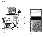
- FIG. 2 shows a work station intended for an agent 1.
- a data processing system 7 with a keyboard 22 and with an output device 8 is via a line 4 to the switching device 10 connected.
- a screen is used as the output device 8 intended.
- the voice terminal 2 is connected to the data processing system via lines 3, 5 7 and / or with the switching device 10 connected.
- a detector 6 is provided. Different devices for the detection of an agent are subsequently described in several Described examples.
- the detector 6 is designed as a pressure sensor and connected to the chair 16.
- the pressure sensor places a load the chair 16 firmly.
- the pressure sensor is in the cushion Seat 17 of a chair 16 provided for each work station 1 built-in.
- a control circuit 18 is assigned to the pressure sensor.
- the pressure sensor is connected to the data processing system 7 connected via a line 19 and dimensioned so that a Stress on the chair 16 by accidentally being placed on the chair Objects such as Briefcase or portable computer not as an occupancy is registered.
- connection of pressure sensors can be carried out according to the in [4] page 908 ff. contained rules.
- Connection to a data processing system 7 is known in principle and is the same such as. the connection of a joystick.
- the login / logout procedure is advantageously carried out with a resident program.
- Such a program is preferred at the start of the applications in the main memory of the data processing system 7 loaded. Depending on the operating system used can use this program as a utility and / or be designed as a device driver.
- the detectors 6 are also directly connected to the switching device 10 are connected. Conveniently a concentrator is used for this.
- the origin of the incoming Detector signals is due to the pin assignment from Concentrator registered as an address.
- Fig. 3 shows a workplace 1, in which the detector 6 with a line 19 'to that assigned to the data processing system 7 Keyboard 22 is connected. Also the voice terminal 2 can be connected to the keyboard 22 in a preferred embodiment his.
- the for the transmission of the detector signals and at most channels necessary for the transmission of the speech and / or lines can be used in addition to the keyboard connection 22 and data processing system 7 are provided. It is but also possible for the connection between keyboard 22 and Data processing system 7 to provide a USB interface (USB: Universal Serial Bus).
- USB Universal Serial Bus
- On Detector detects a displacement 20 of the seat 17.
- a displacement of the seat surface 17 results from a load the chair 16 by the body weight of an agent.
- Detector can be, for example, a reed relay, a switch an associated actuation mechanism or a light barrier be used.
- Reed relays and an associated magnet are attached to or in the foot of the chair so that a change in load to a relative movement magnet - reed relay leads and triggers a change in the state of the reed relay. This.
- Relative motion can also be used to operate a switch or to interrupt the light beam of a light barrier or to release again.
- the occupancy status "agent present” or “agent absent” are either due to a detected change in occupancy or at a fixed time to the login / logout procedure to hand over. Depending on the habits of the person concerned Agents can configure such a timing of the associated data processing system 7 in one certain range.
- the detector 6 can also perform very short-term movements Capture agents. So that such changes in movement do not increase a change in occupancy status to be registered can the control circuit with a dead time element and / or with a Integrator be provided. This changes the occupancy status only then to the switching device 10 forwarded when the loads detected by the detector are reasonably constant over time.
- Detector signals in the control circuit 18 can be evaluated and smoothing in the data processing system 7 of the workplace 1 be made.
- a wireless Transfer of occupancy status from detectors to one receiver unit that can be connected to the data processing system be provided.
- the transmission method uses either the Infrared range or one approved for such purposes Radio frequency range.
- a detector 6 is arranged on the output device 8 and connected to the data processing system 7 via a line 19.
- An infrared sensor can be used as the detector 6.
- the infrared sensor measures the heat radiation emitted by a person.
- the reception characteristics of this infrared sensor are selected so that an agent can move a bit at his workstation 1 A , 1 B , ..., 1 X, both laterally and in depth, without this causing a significantly significant change in the measured value.
- the reception characteristic includes a certain sector, preferably in the order of 120 °.
- the distance that such an infrared sensor should still recognize can be set via a threshold value. It should be taken into account that the heat radiation output decreases quadratically with the distance.
- the threshold value can be set either on the infrared sensor or in a program part of the data processing system 7.
- a light barrier is provided as detector 6.
- the beam of light this light barrier is arranged so that it is present an agent is interrupted at a workplace.
- the detector designed as a light barrier or as an infrared sensor can also in the housing of the output device 8 or in a Video camera installed.
- the video camera is preferably on or arranged next to the output device.
- the video camera can also be provided as a recording camera of a video phone.
- An ultrasound motion detector can also be provided as the detector 6 are preferably arranged on the output device 8 is.
- an ultrasonic motion detector the device from the company SWEL in D-17509 Kemnitz Type "SWEL presence sensor CUBI" can be used. Details for this device, see the document [13].
- Such Ultrasonic motion detectors work according to the ultrasonic echo method. The ultrasound motion detector sends short sound impulses and registers the resulting echo. An analysis of the echo becomes an "agent present" signal or "agent absent”. With such ultrasonic motion detectors the range is preferably adjustable.
- the invention is not limited to the above described detectors limited. Others can also Measurement sensors and sensors for detection known to those skilled in the art used by agents.
- a voice terminal 6 it is also possible to use one Headset consisting of headphones and microphone to be provided.
- Operations of the agent such as entering a call, transfer of a call or termination a call is made via the data processing system. Entries are made by the agent using the keyboard 22, the signaling of connection states can be acoustic and / or also take place optically via the output unit 8.
- the detection of agents at workplaces 1 A , 1 B , 1 C , ..., 1 X can be expanded to identify agents.
- the persons to be admitted to the workplaces 1 A , 1 B , 1 C , ..., 1 X are registered in an initial setting by storing personal data such as name and profile and characteristic data identifying these persons in the database 13. The data required for identifying the authorized agents is thus stored in the switching device 10.
- the identification can be done with a facial recognition of the agents respectively.
- Devices and methods for facial recognition are e.g. known from [7].
- this identification with a Barcode strips to be worn by the agent on a piece of clothing or with a transponder carried by the agent, preferably a surface wave component.
- the facial images are processed by the video camera in the associated data processing system 7 into feature data and compared with the feature data stored in the database 13. If they are identical, a login procedure is started and the relevant work station is registered in the occupancy table of the call distribution unit 15 with the occupancy status "agent present". The identity of the agent in question is also stored in the occupancy table.
- the video camera can be the face of an agent in an adjustable manner Scan the timing.
- an identity card with personal details in the form of text, image and barcode is known from [5].
- the agents wear an identity card that is attached to a piece of clothing and has at least one barcode strip.
- An individually defined barcode is provided for each agent.
- a workstation 1 A , 1 B , 1 C , ..., 1 X is assigned a barcode reader that can reliably read a barcode strip up to a distance of approx. 1 m.
- a barcode reader can be connected to the data processing system 7 according to the rules specified in [6].
- page 29 is the use of SAW or SAW (surface waves or surface acoustic waves) - components for identification known from automobiles that pass through a control station.
- the SAW component is able to receive one Convert the signal into a surface wave, which is reflected in the Spreads surface of the SAW component.
- On the surface of the SAW components are electroacoustic transducers and reflectors provided that are able to part of the bypassing them Surface waves again in electrical signals convert and reflect.
- [8] shows an interrogation unit and associated transponders known that allow identification of a moving object.
- a transponder is assigned to a moving object, the transponder when queried by the stripping unit give an individual response signal.
- Each agent carries a transponder assigned to it, for example in the form of a small one in a pocket Garment carried trailer.
- At least one of the workstations 1 A , 1 B , 1 C , ..., 1 X is assigned a removal unit designed as a detector 6; which determines the presence and identity of a transponder in the immediate vicinity.
- the interrogation unit is connected to the data processing system 7.
- the data uniquely identifying a transponder is stored in the switching device 10 as feature data. If an agent with a transponder is in the immediate vicinity of a workplace, this is registered by the interrogation unit.
- the identity of the agent in question is fed to the switching device 10 via the data processing system 7 and compared there with the stored feature data. In the case of equality, the agent and the relevant workplace are registered.
- the extension of the invention to identify agents has the advantage that agents can arbitrarily select the workstations 1 A , 1 B , 1 C , ..., 1 X connected to such a switching device 10.
- the presence of an agent at a workstation 1 A , 1 B , ..., 1 X starts a login procedure without further interaction by the agent.
- the presence of an agent at a workstation 1 A , 1 B , 1 C ,..., 1 X is reported to the switching device 10 and the occupancy status and the ascertained identity of an agent are registered in the occupancy table of the call distribution unit 15.
Landscapes
- Business, Economics & Management (AREA)
- Marketing (AREA)
- Engineering & Computer Science (AREA)
- Signal Processing (AREA)
- Telephonic Communication Services (AREA)
- Management, Administration, Business Operations System, And Electronic Commerce (AREA)
Abstract
Description
- Fig. 1
- ein Blockschaltbild einer Vermittlungsvorrichtung 10 mit der Anschaltung von Arbeitsplätzen 1A, 1B, 1C, ... , 1X ;
- Fig. 2
- einen Arbeitsplatz 1 mit einem zugeordneten Detektor 6 und die Anschaltung an eine Vermittlungsvorrichtung 10 und
- Fig. 3
- einen Arbeitsplatz 1 mit einem zugeordneten Detektor 6 und die Anschaltung an eine Vermittlungsvorrichtung 10 mit einer Zwischenschaltung eines Datenverarbeitungssystems.
- 1
- Arbeitsplatz
- 2
- Sprachendgerät
- 3
- Verbindung Sprachendgerät - Datenverarbeitungssystem
- 4
- Verbindung Datenverarbeitungssystem - Vermittlungsvorrichtung
- 5
- Verbindung Sprachendgerät Vermittlungsvorrichtung
- 5'
- Verbindung Sprachendgerät - Tastatur
- 6
- Detektor
- 7
- Datenverarbeitungssystem
- 8
- Ausgabegerät
- 9
- Netzwerk
- 10
- Vermittlungsvorrichtung
- 11a
- Anschlusseinheit
- 11b
- Anschlusseinheit
- 12
- Durchschalteeinheit
- 13
- Datenbank
- 14
- Sprachbeantwortungseinheit
- 15
- Anrufverteilungseinheit
- 16
- Stuhl
- 17
- Sitzfläche
- 18
- Ansteuerschaltung
- 19
- Verbindung Detektor - Datenverarbeitungssystem
- 19'
- Verbindung Detektor - Tastatur
- 20
- Verschiebung der Sitzfläche
- 21
- Bussystem
- 22
- Tastatur
Method and apparatus for automatically distributing calls to available logged-in callhandling agents
Call distribution based an agent occupancy
System tor producing a personal ID card
PCMCIA interface card for coupling input devices such as barcode scanning engines to personal digital assistants and palmtop computers
Personal access control system using speech and face recognition
Arrangement for identification of a movable object having a transponder
Claims (17)
- Vorrichtung zur Vermittlung (10) von Anrufen und/oder Meldungen an für Agenten vorgesehene Arbeitsplätze (1, 1A, 1B, 1C, ... , 1X), die ein Datenverarbeitungssystem (7) und/oder ein Sprachendgerät (2) aufweisen, welche mit der Vermittlungsvorrichtung (10) verbunden sind, dadurch gekennzeichnet, dass jedem Arbeitsplatz (1, 1A, 1B, 1C, ..., 1X) wenigstens ein mit der Vermittlungsvorrichtung (10) verbundener Detektor (6) zugeordnet ist, durch den die Anwesenheit eines Agenten und somit die tatsächliche Belegung des Arbeitsplatzes (1, 1A, 1B, 1C, ... , 1X) feststellbar ist, dass die von den Detektoren (6) festgestellten Belegungszustände der Arbeitsplätze (1, 1A, 1B, 1C, ... , 1X) der Vermittlungsvorrichtung (10) zuführbar und dort registrierbar sind und dass die zu vermittelnden Anrufe und/oder Meldungen von der Vermittlungsvorrichtung (10) in Abhängigkeit der registrierten Belegungszustände an Arbeitsplätze (1, 1A, 1B, 1C, ... , 1X) durchachaltbar sind, die durch einen Agenten belegt sind.
- Vorrichtung nach Anspruch 1, dadurch gekennzeichnet, dass der Detektor (6) direkt mit der Vermittlungsvorrichtung (10) oder mit dem Datenverarbeitungssystem (7) verbunden ist, über welche die vom Detektor (6) festgestellten Belegungszustände an die Vermittlungsvorrichtung (10) weitergeleitet werden.
- Vorrichtung nach Anspruch 1, dadurch gekennzeichnet, dass der Detektor (6) über die einem Datenverarbeitungssystem (7) zugeordnete Tastatur (22) mit dem Datenverarbeitungssystem (7) verbunden ist, über die vom Detektor (6) festgestellten Belegungszustände an die Vermittlungsvorrichtung (10) weitergeleitet werden.
- Vorrichtung nach einem der Ansprüche 1 bis 3, dadurch gekennzeichnet, dass wenigstens einem Arbeitsplatz (1) ein für den entsprechenden Agenten vorgesehener Stuhl (16) zugeordnet ist, der derart mit einem Detektor (6) versehen ist, dass die Belastung des Stuhles (16) durch das Körpergewicht des Agenten als Belegung des Arbeitsplatzes (10) interpretiert und der Vermittlungsvorrichtung (6) gemeldet wird.
- vorrichtung nach Anspruch 4, dadurch gekennzeichnet, dass die Sitzfläche (17) des Stuhls (16) elastisch gelagert ist, wobei die Belastung des Stuhls (16) durch das Körpergewicht des Agenten bzw. die entsprechende Verschiebung der Sitzfläche (16, 20) durch den Detektor (6) feststellbar ist.
- Vorrichtung nach Anspruch 5, dadurch gekennzeichnet, dass der Detektor (6) ein Sensorelement umfasst, das zur Messung der Änderung eines Druckes, eines magnetischen Feldes oder eines Lichtstromes dient, die bei Verschiebung der Sitzfläche (16, 20) verursacht wird.
- Vorrichtung nach Anspruch 5, dadurch gekennzeichnet, dass der Detektor (6) einen Schalter aufweist, der bei Verschiebung der Sitzfläche (16, 20) betätigt wird.
- Vorrichtung nach einem der Ansprüche 1 bis 3, dadurch gekennzeichnet, dass der Detektor (6) einen Infrarotsensor aufweist, durch den die Wärmeabstrahlung des Agenten erfasst wird, sobald er sich im Bereich eines Arbeitsplatzes (1, 1A, 1B, 1C, ... , 1X) aufhält.
- Vorrichtung nach einem der Ansprüche 1 bis 3, dadurch gekennzeichnet, dass der Detektor (6) mit wenigstens einer Lichtschranke verbunden ist, die derart angeordnet ist, dass deren Lichtstrahl unterbrochen wird, sobald sich ein Agent im unmittelbaren Bereich des Arbeitsplatzes (1) aufhält.
- Vorrichtung nach Anspruch 8 oder 9, dadurch gekennzeichnet, dass der Detektor (6) in einem mit dem Datenverarbeitungssystem (7) verbundenen Ausgabegerät (8) oder in einer mit dem Datenverarbeitungssystem (7) verbundenen Videokamera eingebaut ist.
- Vorrichtung nach einem der Ansprüche 1 bis 9, dadurch gekennzeichnet, dass die Verbindung zwischen dem Detektor (6) und der Vermittlungsvorrichtung (10) oder dem Datenverarbeitungssystem (7) drahtlos herstellbar ist.
- Vorrichtung nach einem der Ansprüche 1 bis 11, dadurch gekennzeichnet, dass einen Agenten kennzeichnende Merkmale vom Detektor (6) erfassbar sind und dazu korrespondierende Merkmalsdaten der Vermittlungsvorrichtung (10) zuführbar sind, mit in einer Datenbank (13) vorgängig gespeicherten Merkmalsdaten von bestimmten Agenten vergleichbar sind und dadurch der aus dem Vergleich resultierende Belegungszustand des betreffenden Arbeitsplatzes (1, 1A, 1B, 1C, ... , 1X) in der Vermittlungsvorrichtung (10) registrierbar ist.
- Vorrichtung nach Anspruch 12, dadurch gekennzeichnet, dass der Detektor (6) als Videokamera ausgebildet ist und die einen Agenten kennzeichnenden Merkmale aus einer Gesichtserkennung gebildet werden.
- Vorrichtung nach Anspruch 12, dadurch gekennzeichnet, dass der Detektor (6) als Barcode-Lesegerät ausgebildet ist und die kennzeichnenden Merkmale aus von Agenten zu tragenden und individuell zugeordneten Barcode-Streifen gebildet werden.
- Vorrichtung nach Anspruch 12, dadurch gekennzeichnet, dass der Detektor (6) als Abfrageeinheit für Transponder ausgebildet ist und die kennzeichnenden Merkmale aus von Agenten zu tragenden und individuell zugeordneten Transpondern gebildet werden.
- Vorrichtung nach Anspruch 15, dadurch gekennzeichnet, dass der Detektor (6) als Abfrageeinheit für Oberflächenwellenbauteile ausgebildet ist und die kennzeichnenden Merkmale aus von Agenten zu tragenden und individuell zugeordneten Oberflächenwellenbauteilen gebildet werden.
- Vorrichtung nach einem der Ansprüche 1, 2, 3 oder 11, dadurch gekennzeichnet, dass der Detektor (6) einen Ultraschallsensor aufweist, durch den das Echo von ausgesandten Ultraschallimpulsen registrierbar und als festgestellter Belegungszustand an die Vermittlungsvorrichtung zuführbar ist.
Applications Claiming Priority (4)
| Application Number | Priority Date | Filing Date | Title |
|---|---|---|---|
| CH4999 | 1999-01-13 | ||
| CH4999 | 1999-01-13 | ||
| CH45799 | 1999-03-11 | ||
| CH45799 | 1999-03-11 |
Publications (2)
| Publication Number | Publication Date |
|---|---|
| EP1021028A2 true EP1021028A2 (de) | 2000-07-19 |
| EP1021028A3 EP1021028A3 (de) | 2004-01-07 |
Family
ID=25683363
Family Applications (1)
| Application Number | Title | Priority Date | Filing Date |
|---|---|---|---|
| EP00100344A Withdrawn EP1021028A3 (de) | 1999-01-13 | 2000-01-07 | Vorrichtung zur Vermittlung von Anrufen oder Meldungen an für Agenten vorgesehene Arbeitsplätze |
Country Status (1)
| Country | Link |
|---|---|
| EP (1) | EP1021028A3 (de) |
Cited By (1)
| Publication number | Priority date | Publication date | Assignee | Title |
|---|---|---|---|---|
| EP1793576A1 (de) * | 2005-11-30 | 2007-06-06 | Avaya Technology Llc | Verfahren und Gerät zum dynamischen Einstellen von Mitteln in einer Anrufzentrale |
Family Cites Families (6)
| Publication number | Priority date | Publication date | Assignee | Title |
|---|---|---|---|---|
| US4449189A (en) * | 1981-11-20 | 1984-05-15 | Siemens Corporation | Personal access control system using speech and face recognition |
| US4932050A (en) * | 1989-06-30 | 1990-06-05 | At&T Bell Laboratories | Proximity detection for telecommunications features |
| US5226077A (en) * | 1992-03-02 | 1993-07-06 | Acs Communications, Inc. | Headset amplifier with automatic log on/log off detection |
| JPH06296148A (ja) * | 1993-04-07 | 1994-10-21 | Shiroki Corp | 在席確認装置 |
| US5505494B1 (en) * | 1993-09-17 | 1998-09-29 | Bell Data Software Corp | System for producing a personal id card |
| DE4417688C1 (de) * | 1994-05-20 | 1995-07-13 | Licentia Gmbh | Beweglicher Gegenstand mit einem Transponder |
-
2000
- 2000-01-07 EP EP00100344A patent/EP1021028A3/de not_active Withdrawn
Cited By (1)
| Publication number | Priority date | Publication date | Assignee | Title |
|---|---|---|---|---|
| EP1793576A1 (de) * | 2005-11-30 | 2007-06-06 | Avaya Technology Llc | Verfahren und Gerät zum dynamischen Einstellen von Mitteln in einer Anrufzentrale |
Also Published As
| Publication number | Publication date |
|---|---|
| EP1021028A3 (de) | 2004-01-07 |
Similar Documents
| Publication | Publication Date | Title |
|---|---|---|
| DE19832433B4 (de) | Einrichtung zum Erstellen und Aufrufen von Benutzerprofilen in einem Nachrichtensystem | |
| DE69509755T2 (de) | Telefonkommunikationssystem mit einem lokalisierer | |
| WO1995034985A1 (de) | Verfahren zur auswahl eines von mindestens zwei fernmeldeendgeräten und fernmeldeendgerät dafür | |
| WO1996031045A1 (de) | Türrufbeantworter | |
| EP1357464A3 (de) | Verfahren, Vorrichtung und Programm zur Verwaltung des Betriebs eines Speichergeräts | |
| EP1992148B1 (de) | Verfahren und telefon zur nutzung von in einer telefonbuchdatenbank eines servers gespeicherten telefonbuchdaten | |
| CN102739879A (zh) | 移动话音服务者访问 | |
| DE202007018516U1 (de) | Türzugangssystem mit einer eine Kamera aufweisenden Türstation | |
| JPS63299659A (ja) | 緊急通報者位置表示方式 | |
| DE19628764A1 (de) | Türgegensprechanlage | |
| EP1601213A1 (de) | Verfahren und System zur automatisierten Rufumleitung | |
| DE19826087C2 (de) | Einrichtung einer Endstelle eines Telekommunikationsnetzes | |
| DE69935453T2 (de) | Wechsel zwischen funktionsweisen eines endgeräts an einer nebenstellenanlage | |
| JPS63163599A (ja) | 在席検知システム | |
| DE3513244C2 (de) | ||
| KR100351974B1 (en) | Telephone connection system | |
| DE4425882A1 (de) | System und Verfahren zur örtlichen und zeitlichen Erfassung von Identifikationsangaben | |
| JP3075815U (ja) | インドア試験用携帯電話電波品質測定装置 | |
| DE19920223B4 (de) | Verfahren und Vorrichtung zur Übertragung von Informationen an eine Person | |
| DE3900364A1 (de) | Realisierung von buero- und auskunftssystemen unter verwendung digitaler telefonanlagen | |
| EP1079588B1 (de) | Verfahren zur Durchführung eines automatischen Rückrufs und Telekommunikationsendgerät dafür | |
| WO2007006703A1 (de) | Verfahren zur optimierung von kontrollvorgängen beim einsatz mobiler endgeräte | |
| EP1130796A3 (de) | Verfahren und Vorrichtung zur Durchführung von Echokompensation in einem Kommunikationsnetzwerk | |
| KR960027925A (ko) | 키폰 시스템 및 그것의 출퇴근 점검방법 | |
| JPH0334731A (ja) | コードレス電話機 |
Legal Events
| Date | Code | Title | Description |
|---|---|---|---|
| PUAI | Public reference made under article 153(3) epc to a published international application that has entered the european phase |
Free format text: ORIGINAL CODE: 0009012 |
|
| AK | Designated contracting states |
Kind code of ref document: A2 Designated state(s): AT BE CH CY DE DK ES FI FR GB GR IE IT LI LU MC NL PT SE |
|
| AX | Request for extension of the european patent |
Free format text: AL;LT;LV;MK;RO;SI |
|
| PUAL | Search report despatched |
Free format text: ORIGINAL CODE: 0009013 |
|
| AK | Designated contracting states |
Kind code of ref document: A3 Designated state(s): AT BE CH CY DE DK ES FI FR GB GR IE IT LI LU MC NL PT SE |
|
| AX | Request for extension of the european patent |
Extension state: AL LT LV MK RO SI |
|
| AKX | Designation fees paid | ||
| REG | Reference to a national code |
Ref country code: DE Ref legal event code: 8566 |
|
| STAA | Information on the status of an ep patent application or granted ep patent |
Free format text: STATUS: THE APPLICATION IS DEEMED TO BE WITHDRAWN |
|
| 18D | Application deemed to be withdrawn |
Effective date: 20040803 |