EP1020609A1 - Halteleiste und zugeordnetes Rahmenprofil für eine Fenster-, Tür- oder Festverglasung oder für eine Füllungsplatte - Google Patents
Halteleiste und zugeordnetes Rahmenprofil für eine Fenster-, Tür- oder Festverglasung oder für eine Füllungsplatte Download PDFInfo
- Publication number
- EP1020609A1 EP1020609A1 EP00100547A EP00100547A EP1020609A1 EP 1020609 A1 EP1020609 A1 EP 1020609A1 EP 00100547 A EP00100547 A EP 00100547A EP 00100547 A EP00100547 A EP 00100547A EP 1020609 A1 EP1020609 A1 EP 1020609A1
- Authority
- EP
- European Patent Office
- Prior art keywords
- frame profile
- leg
- fastening
- associated frame
- profile according
- Prior art date
- Legal status (The legal status is an assumption and is not a legal conclusion. Google has not performed a legal analysis and makes no representation as to the accuracy of the status listed.)
- Granted
Links
Images
Classifications
-
- E—FIXED CONSTRUCTIONS
- E06—DOORS, WINDOWS, SHUTTERS, OR ROLLER BLINDS IN GENERAL; LADDERS
- E06B—FIXED OR MOVABLE CLOSURES FOR OPENINGS IN BUILDINGS, VEHICLES, FENCES OR LIKE ENCLOSURES IN GENERAL, e.g. DOORS, WINDOWS, BLINDS, GATES
- E06B5/00—Doors, windows, or like closures for special purposes; Border constructions therefor
- E06B5/10—Doors, windows, or like closures for special purposes; Border constructions therefor for protection against air-raid or other war-like action; for other protective purposes
- E06B5/11—Doors, windows, or like closures for special purposes; Border constructions therefor for protection against air-raid or other war-like action; for other protective purposes against burglary
- E06B5/116—Arrangements preventing the removal of glazing panels
-
- E—FIXED CONSTRUCTIONS
- E06—DOORS, WINDOWS, SHUTTERS, OR ROLLER BLINDS IN GENERAL; LADDERS
- E06B—FIXED OR MOVABLE CLOSURES FOR OPENINGS IN BUILDINGS, VEHICLES, FENCES OR LIKE ENCLOSURES IN GENERAL, e.g. DOORS, WINDOWS, BLINDS, GATES
- E06B3/00—Window sashes, door leaves, or like elements for closing wall or like openings; Layout of fixed or moving closures, e.g. windows in wall or like openings; Features of rigidly-mounted outer frames relating to the mounting of wing frames
- E06B3/54—Fixing of glass panes or like plates
- E06B3/58—Fixing of glass panes or like plates by means of borders, cleats, or the like
- E06B3/5807—Fixing of glass panes or like plates by means of borders, cleats, or the like not adjustable
Definitions
- the invention relates to a retaining bar and an associated frame profile, for a window, door or fixed glazing or for a panel, the Holding strip one with one on the edge of the glass pane or the infill panel supporting seal provided outer leg and an angled to it extending fastening leg.
- a retaining strip of this type is known, the fastening legs of which are partially a plastic holder is enclosed and in a C-shaped anchoring groove Frame profile swung in and firmly and positively attached to the frame profile becomes. If this retaining strip is mitred, assembly is required the holding strips forming the corner are not possible. Also bending these retaining strips to an arcuate contour with a relatively small radius is not feasible. In addition, the anchoring of the retaining bar relative to the frame profile is not designed to be sufficiently burglar-resistant.
- the invention has for its object a retaining bar of the aforementioned To be designed in such a way that it is burglar-resistant, mitred, easily assembled and in arcuate corners one of a Glass pane or a plate filled field can be laid.
- the frame profile has one adjacent to the outer longitudinal edge C-shaped anchoring groove, which is limited by edge strips.
- the fastening leg of the retaining strip is pushed onto the edge strips.
- the screw connection takes place in the area of the anchoring groove.
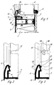
- a composite panel 1 of a door leaf is shown, with a recess filled by a glass pane 2 or by another plate 3 is provided.
- the glass pane or filling plate 2 is on the outside in the edge area by a holding strip 4 and fixed inside by a retaining strip 5.
- the holding strip 4 has an outer leg 6 and a fastening leg 7 which form a right angle ⁇ .
- the holding strip is provided with a contact web 8, which is from the outer leg 6 goes out and extends over the mounting leg 7.
- the landing stage 8 limits due to its abutment on the outer surface of the frame profile 9, the assembly movement the retaining strip 4, which with its mounting leg 7 on the Edge strips 10 and 11 of a C-shaped anchoring groove 12 are supported.
- the fastening leg 7 is attached to the frame profile by means of fastening screws 13 9 set.
- the mounting screws are spaced apart are screwed directly into the frame profile or into a sliding block 14 become.
- the fastening screws are then preassembled and inserted the retaining strip 4 in the final assembly position.
- the mounting leg 7 at the points where screws are to be provided, equipped with elongated holes 15, the side facing away from the outer leg are open.
- the elongated hole 15 is a little wider formed as the threaded shaft of the mounting screw 13.
- the one The flat-headed fastening screw is supported with its head in the edge area of the elongated hole 15.
- the fastening leg 7 of the retaining strip In the formation of the fastening leg 7 of the retaining strip according to FIG. 3 the elongated holes 16 at the end facing the outer leg 6 with a bore 17 provided.
- fastening screws are used that have a countersunk head which is to be received by the bore 17. So when screwing the fastening screw into the assigned slot nut the retaining strip has a transverse movement in the direction of the filling plate or Glass plate 2 is abandoned, the longitudinal axis 18 of the screw when screwing offset from the center 19 of the bore to that facing away from the outer leg 6 Page.
- the countersunk head of the fastening screw pulls when tightening the screw into the bore 17 and moves the retaining strip in the direction on the filling plate or glass pane up to the contact web 8 for contact with the outer surface of the frame profile comes.
- the retaining bar is burglar-proof attached to the frame profile 9.
- the outer leg 6 has an inner chamber 20 on the glass pane or the filling plate 2 facing
- the wall 21 extends from the outer edge 22 of the outer leg 6 in parallel to the glass pane or infill panel 2. It ends at a projecting anchoring bar 23 for a plug keder seal 24.
- the of the anchoring web 23 outgoing wall 25 runs obliquely in the direction of the glass pane or filling panel 2 and forms a support for the plug keder seal.
- the outer wall 26 of the outer leg 6 extends in an arc.
- the contour of the outer wall can also have a geometric shape that deviates from the arch shape Contour have this in the area of the visible side of the holding bar to give the desired design.
Landscapes
- Engineering & Computer Science (AREA)
- Civil Engineering (AREA)
- Structural Engineering (AREA)
- Securing Of Glass Panes Or The Like (AREA)
Abstract
Description
- Figur 1
- die Randeinfassung einer Glasscheibe oder Füllungsplatte im Vertikalschnitt,
- Figur 2
- in vergrößertem Maßstab die in der Fig. 1 dargestellte Halteleiste in perspektivischer Darstellung und
- Figur 3
- eine Abwandlungsform zu der Ausführung nach der Fig. 2.
Claims (12)
- Halteleiste und zugeordnetes Rahmenprofil für eine Fenster-, Tür- oder Festverglasung oder für eine Füllungsplatte mit einem mit einer sich am Rand der Glasscheibe oder der Füllungsplatte abstützenden Dichtung versehenen Außenschenkel sowie mit einem winklig dazu sich erstreckenden Befestigungsschenkel, dadurch gekennzeichnet, daß der Außenschenkel (6) und der Befestigungsschenkel (7) einen Winkel α bilden und der Befestigungsschenkel (7) mit dem Rahmenprofil (9) verschraubbar ist, wobei der Befestigungsschenkel (7) mit der Ebene der Glasscheibe oder der Füllungsplatte (2) einen Winkel β gleich oder kleiner 90° bildet..
- Halteleiste und zugeordnetes Rahmenprofil, dadurch gekennzeichnet, daß sie einen vom Außenschenkel (6) ausgehenden, sich über den Befestigungsschenkel (7) hinaus erstreckenden, mit dem Rahmenprofil (9) zusammenwirkenden Anlagesteg (8) aufweist.
- Halteleiste und zugeordnetes Rahmenprofil, das mit einer durch Randleisten begrenzten Verankerungsnut ausgerüstet ist, dadurch gekennzeichnet, daß der Befestigungsschenkel (7) sich außen an den Randleisten (10,11) abstützt und die Befestigungsschrauben (13) im Bereich der Verankerungsnut (12) in das Rahmenprofil (9) oder in ein mit dem Rahmenprofil verbundenes Beschlagteil geschraubt sind.
- Halteleiste und zugeordnetes Rahmenprofil nach einem der vorhergehenden Ansprüche, dadurch gekennzeichnet, daß der Befestigungsschenkel (7) im Abstand der vorgesehenen Befestigungsschrauben (13) zum freien Längsrand geöffnete Langlöcher (15,16) aufweist.
- Halteleiste und zugeordnetes Rahmenprofil nach Anspruch 4, dadurch gekennzeichnet, daß die Befestigungsschrauben sich mit ihren Köpfen im Längsrandbereich der Langlöcher (15) abstützen.
- Halteleiste und zugeordnetes Rahmenprofil nach Anspruch 4, dadurch gekennzeichnet, daß die Langlöcher (16) an dem dem Außenschenkel (6) zugewandten Ende mit einer Bohrung (17) für den als Senkkopf ausgebildeten Schraubenkopf der Befestigungsschraube (13) versehen sind und die Längsachse (18) der Befestigungsschrauben (13) beim Eindrehen in das Rahmenprofil oder in ein mit dem Rahmenprofil verbundenen Teil gegenüber der Mitte (19) der Bohrung zu der dem Außenschenkel (6) abgewandten Seite versetzt ist.
- Halteleiste und zugeordnetes Rahmenprofil nach Anspruch 3, dadurch gekennzeichnet, daß in der Verankerungsnut (12) Nutensteine (14) angeordnet sind und der Gewindeschaft einer jeden Befestigungsschraube in einen Nutenstein eingeschraubt wird.
- Halteleiste und zugeordnetes Rahmenprofil nach Anspruch 7, dadurch gekennzeichnet, daß die Nutensteine (14) im Abstand der Befestigungspunkte für die Halteleiste (4) in der Verankerungsnut (12) des Rahmenproflls (9) festgelegt werden und nach dem Eindrehen der Befestigungsschrauben in eine Vormontagestellung der Befestigungsschenkel (7) quer zur Längsachse auf die Randleisten (10,11) der Verankerungsnut (12) schiebbar ist.
- Halteleiste und zugeordnetes Rahmenprofil nach Anspruch 1, dadurch gekennzeichnet, daß der Außenschenkel (6) mit einer Innenkammer (20) ausgerüstet ist.
- Halteleiste und zugeordnetes Rahmenprofil nach Anspruch 9, dadurch gekennzeichnet, daß die Wand (21) der Innenkammer (20) an der der Glasscheibe oder der Füllungsplatte (2) zugewandten Seite von dem äußeren Rand (22) des Außenschenkels (6) annähernd parallel zur Glasscheibe oder Füllungsplatte (2) verläuft bis zu einem vorspringenden Verankerungssteg (23) für eine Steckkederdichtung (24) und die Wand (25) ausgehend von dem Verankerungssteg (23) schräg in Richtung zur Glasscheibe oder Füllungsplatte (2) verläuft und eine Auflage für die Steckkederdichtung bildet.
- Halteleiste und zugeordnetes Rahmenprofil nach Anspruch 9 oder 19, dadurch gekennzeichnet, daß die Außenwand (26) des Außenschenkels (6) bogenförmig verläuft.
- Halteleiste und zugeordnetes Rahmenprofil nach Anspruch 1, dadurch gekennzeichnet, daß der Winkel α ein rechter Winkel ist.
Applications Claiming Priority (2)
| Application Number | Priority Date | Filing Date | Title |
|---|---|---|---|
| DE29900779U | 1999-01-18 | ||
| DE29900779U DE29900779U1 (de) | 1999-01-18 | 1999-01-18 | Halteleiste und zugeordnetes Rahmenprofil für eine Fenster-, Tür- oder Festverglasung oder für eine Füllungsplatte |
Publications (2)
| Publication Number | Publication Date |
|---|---|
| EP1020609A1 true EP1020609A1 (de) | 2000-07-19 |
| EP1020609B1 EP1020609B1 (de) | 2005-10-12 |
Family
ID=8068140
Family Applications (1)
| Application Number | Title | Priority Date | Filing Date |
|---|---|---|---|
| EP00100547A Expired - Lifetime EP1020609B1 (de) | 1999-01-18 | 2000-01-12 | Halteleiste und zugeordnetes Rahmenprofil für eine Fenster-, Tür- oder Festverglasung oder für eine Füllungsplatte |
Country Status (4)
| Country | Link |
|---|---|
| EP (1) | EP1020609B1 (de) |
| AT (1) | ATE306604T1 (de) |
| DE (2) | DE29900779U1 (de) |
| ES (1) | ES2246757T3 (de) |
Families Citing this family (1)
| Publication number | Priority date | Publication date | Assignee | Title |
|---|---|---|---|---|
| DE102005023257A1 (de) * | 2005-05-20 | 2006-11-23 | Hermann Gutmann Werke Ag | Halteprofil sowie Fenster- oder Türkonstruktion |
Citations (5)
| Publication number | Priority date | Publication date | Assignee | Title |
|---|---|---|---|---|
| US1969995A (en) * | 1934-02-14 | 1934-08-14 | Valentine L Thoma | Window sash |
| US1981193A (en) * | 1933-03-27 | 1934-11-20 | Kawneer Co | Store front construction |
| US2602528A (en) * | 1939-06-15 | 1952-07-08 | Hallauer Walter | Fastener for show windows |
| NL274503A (de) * | 1961-02-07 | 1964-09-25 | ||
| DE1939761A1 (de) * | 1968-08-06 | 1970-02-12 | Zwaan Adrianus J | Ladenfront- oder aehnliche Konstruktion |
-
1999
- 1999-01-18 DE DE29900779U patent/DE29900779U1/de not_active Expired - Lifetime
-
2000
- 2000-01-12 AT AT00100547T patent/ATE306604T1/de active
- 2000-01-12 ES ES00100547T patent/ES2246757T3/es not_active Expired - Lifetime
- 2000-01-12 EP EP00100547A patent/EP1020609B1/de not_active Expired - Lifetime
- 2000-01-12 DE DE50011307T patent/DE50011307D1/de not_active Expired - Lifetime
Patent Citations (5)
| Publication number | Priority date | Publication date | Assignee | Title |
|---|---|---|---|---|
| US1981193A (en) * | 1933-03-27 | 1934-11-20 | Kawneer Co | Store front construction |
| US1969995A (en) * | 1934-02-14 | 1934-08-14 | Valentine L Thoma | Window sash |
| US2602528A (en) * | 1939-06-15 | 1952-07-08 | Hallauer Walter | Fastener for show windows |
| NL274503A (de) * | 1961-02-07 | 1964-09-25 | ||
| DE1939761A1 (de) * | 1968-08-06 | 1970-02-12 | Zwaan Adrianus J | Ladenfront- oder aehnliche Konstruktion |
Also Published As
| Publication number | Publication date |
|---|---|
| ES2246757T3 (es) | 2006-03-01 |
| DE29900779U1 (de) | 1999-04-08 |
| EP1020609B1 (de) | 2005-10-12 |
| DE50011307D1 (de) | 2006-02-23 |
| ATE306604T1 (de) | 2005-10-15 |
Similar Documents
| Publication | Publication Date | Title |
|---|---|---|
| DE3439436C2 (de) | ||
| DE3714629C2 (de) | Fassadenwand eines Gebäudes | |
| EP1020579B1 (de) | Fassade oder Lichtdach mit einer Dichtung | |
| DE102012010028A1 (de) | Rahmenanordnung für ein sektionaltorpaneel | |
| DE102014103950A1 (de) | Isolierelement für Fassaden- oder Lichtdachkonstruktionen | |
| CH677252A5 (de) | ||
| EP0645504B1 (de) | Pfosten-Riegel-System | |
| DE69027719T2 (de) | Holzumrahmung mit einer Nut für die Verglasung | |
| EP0524631B1 (de) | Halteglied für Isolierglasscheiben | |
| DE8809618U1 (de) | Duschabtrennung | |
| DE29915574U1 (de) | Fassade mit Adapterprofil | |
| EP1020609B1 (de) | Halteleiste und zugeordnetes Rahmenprofil für eine Fenster-, Tür- oder Festverglasung oder für eine Füllungsplatte | |
| DE102004055803A1 (de) | Rahmenloses Isolierglaselement sowie Beschlag- oder Befestigungssystem für das Isolierglaselement | |
| DE19626612C1 (de) | Doppelplattenanordnung | |
| DE2940075A1 (de) | Scheiben-halterung | |
| DE4027335A1 (de) | Halterungsanordung fuer glasscheiben in toren | |
| DE8803359U1 (de) | Fassadenelement | |
| DE2146250A1 (de) | Fenster- bzw. tuerrahmen | |
| DE3513466C2 (de) | ||
| DE102004027042A1 (de) | Isolierglasrahmen | |
| AT502155B1 (de) | Rahmenloses isolierglaselement sowie beschlag- oder befestigungssystem für das isolierglaselement | |
| CH423174A (de) | Rahmen für festverglaste, belüftete oder unbelüftete Fenster, Schaufenster, Trennwände o. dgl. | |
| DE19730461A1 (de) | Mehrteilige Glashalteleiste | |
| EP1072731B1 (de) | Verglasungsrahmen für Montagewände | |
| DE7540299U (de) | Randleistenbeschlag fuer ganzglastueren oder -waende |
Legal Events
| Date | Code | Title | Description |
|---|---|---|---|
| PUAI | Public reference made under article 153(3) epc to a published international application that has entered the european phase |
Free format text: ORIGINAL CODE: 0009012 |
|
| AK | Designated contracting states |
Kind code of ref document: A1 Designated state(s): AT BE CH CY DE DK ES FI FR GB GR IE IT LI LU MC NL PT SE |
|
| AX | Request for extension of the european patent |
Free format text: AL;LT;LV;MK;RO;SI |
|
| 17P | Request for examination filed |
Effective date: 20010112 |
|
| AKX | Designation fees paid |
Free format text: AT CH DE FR LI NL |
|
| RBV | Designated contracting states (corrected) |
Designated state(s): AT BE CH CY DE DK ES FI FR GB GR IE IT LI LU MC NL PT SE |
|
| 17Q | First examination report despatched |
Effective date: 20031105 |
|
| GRAP | Despatch of communication of intention to grant a patent |
Free format text: ORIGINAL CODE: EPIDOSNIGR1 |
|
| GRAS | Grant fee paid |
Free format text: ORIGINAL CODE: EPIDOSNIGR3 |
|
| GRAA | (expected) grant |
Free format text: ORIGINAL CODE: 0009210 |
|
| AK | Designated contracting states |
Kind code of ref document: B1 Designated state(s): AT BE CH CY DE DK ES FI FR GB GR IE IT LI LU MC NL PT SE |
|
| PG25 | Lapsed in a contracting state [announced via postgrant information from national office to epo] |
Ref country code: IE Free format text: LAPSE BECAUSE OF FAILURE TO SUBMIT A TRANSLATION OF THE DESCRIPTION OR TO PAY THE FEE WITHIN THE PRESCRIBED TIME-LIMIT Effective date: 20051012 Ref country code: FI Free format text: LAPSE BECAUSE OF FAILURE TO SUBMIT A TRANSLATION OF THE DESCRIPTION OR TO PAY THE FEE WITHIN THE PRESCRIBED TIME-LIMIT Effective date: 20051012 Ref country code: IT Free format text: LAPSE BECAUSE OF FAILURE TO SUBMIT A TRANSLATION OF THE DESCRIPTION OR TO PAY THE FEE WITHIN THE PRESCRIBED TIME-LIMIT;WARNING: LAPSES OF ITALIAN PATENTS WITH EFFECTIVE DATE BEFORE 2007 MAY HAVE OCCURRED AT ANY TIME BEFORE 2007. THE CORRECT EFFECTIVE DATE MAY BE DIFFERENT FROM THE ONE RECORDED. Effective date: 20051012 |
|
| REG | Reference to a national code |
Ref country code: GB Ref legal event code: FG4D Free format text: NOT ENGLISH |
|
| REG | Reference to a national code |
Ref country code: CH Ref legal event code: EP Ref country code: CH Ref legal event code: NV Representative=s name: KATZAROV S.A. |
|
| REG | Reference to a national code |
Ref country code: IE Ref legal event code: FG4D Free format text: LANGUAGE OF EP DOCUMENT: GERMAN |
|
| GBT | Gb: translation of ep patent filed (gb section 77(6)(a)/1977) | ||
| PG25 | Lapsed in a contracting state [announced via postgrant information from national office to epo] |
Ref country code: DK Free format text: LAPSE BECAUSE OF FAILURE TO SUBMIT A TRANSLATION OF THE DESCRIPTION OR TO PAY THE FEE WITHIN THE PRESCRIBED TIME-LIMIT Effective date: 20060112 Ref country code: GR Free format text: LAPSE BECAUSE OF FAILURE TO SUBMIT A TRANSLATION OF THE DESCRIPTION OR TO PAY THE FEE WITHIN THE PRESCRIBED TIME-LIMIT Effective date: 20060112 Ref country code: SE Free format text: LAPSE BECAUSE OF FAILURE TO SUBMIT A TRANSLATION OF THE DESCRIPTION OR TO PAY THE FEE WITHIN THE PRESCRIBED TIME-LIMIT Effective date: 20060112 |
|
| PG25 | Lapsed in a contracting state [announced via postgrant information from national office to epo] |
Ref country code: MC Free format text: LAPSE BECAUSE OF NON-PAYMENT OF DUE FEES Effective date: 20060131 Ref country code: LU Free format text: LAPSE BECAUSE OF NON-PAYMENT OF DUE FEES Effective date: 20060131 |
|
| REF | Corresponds to: |
Ref document number: 50011307 Country of ref document: DE Date of ref document: 20060223 Kind code of ref document: P |
|
| REG | Reference to a national code |
Ref country code: ES Ref legal event code: FG2A Ref document number: 2246757 Country of ref document: ES Kind code of ref document: T3 |
|
| REG | Reference to a national code |
Ref country code: IE Ref legal event code: FD4D |
|
| ET | Fr: translation filed | ||
| PLBE | No opposition filed within time limit |
Free format text: ORIGINAL CODE: 0009261 |
|
| STAA | Information on the status of an ep patent application or granted ep patent |
Free format text: STATUS: NO OPPOSITION FILED WITHIN TIME LIMIT |
|
| 26N | No opposition filed |
Effective date: 20060713 |
|
| PG25 | Lapsed in a contracting state [announced via postgrant information from national office to epo] |
Ref country code: CY Free format text: LAPSE BECAUSE OF FAILURE TO SUBMIT A TRANSLATION OF THE DESCRIPTION OR TO PAY THE FEE WITHIN THE PRESCRIBED TIME-LIMIT Effective date: 20051012 |
|
| PGFP | Annual fee paid to national office [announced via postgrant information from national office to epo] |
Ref country code: NL Payment date: 20110119 Year of fee payment: 12 |
|
| PG25 | Lapsed in a contracting state [announced via postgrant information from national office to epo] |
Ref country code: PT Free format text: LAPSE BECAUSE OF FAILURE TO SUBMIT A TRANSLATION OF THE DESCRIPTION OR TO PAY THE FEE WITHIN THE PRESCRIBED TIME-LIMIT Effective date: 20051012 |
|
| PGFP | Annual fee paid to national office [announced via postgrant information from national office to epo] |
Ref country code: CH Payment date: 20120124 Year of fee payment: 13 Ref country code: FR Payment date: 20120201 Year of fee payment: 13 |
|
| PGFP | Annual fee paid to national office [announced via postgrant information from national office to epo] |
Ref country code: BE Payment date: 20120123 Year of fee payment: 13 Ref country code: GB Payment date: 20120124 Year of fee payment: 13 |
|
| REG | Reference to a national code |
Ref country code: NL Ref legal event code: V1 Effective date: 20120801 |
|
| PG25 | Lapsed in a contracting state [announced via postgrant information from national office to epo] |
Ref country code: NL Free format text: LAPSE BECAUSE OF NON-PAYMENT OF DUE FEES Effective date: 20120801 |
|
| PGFP | Annual fee paid to national office [announced via postgrant information from national office to epo] |
Ref country code: AT Payment date: 20120123 Year of fee payment: 13 |
|
| PGFP | Annual fee paid to national office [announced via postgrant information from national office to epo] |
Ref country code: ES Payment date: 20120124 Year of fee payment: 13 |
|
| BERE | Be: lapsed |
Owner name: *SCHUCO INTERNATIONAL K.G. Effective date: 20130131 |
|
| REG | Reference to a national code |
Ref country code: CH Ref legal event code: PL |
|
| REG | Reference to a national code |
Ref country code: AT Ref legal event code: MM01 Ref document number: 306604 Country of ref document: AT Kind code of ref document: T Effective date: 20130131 |
|
| GBPC | Gb: european patent ceased through non-payment of renewal fee |
Effective date: 20130112 |
|
| REG | Reference to a national code |
Ref country code: FR Ref legal event code: ST Effective date: 20130930 |
|
| PG25 | Lapsed in a contracting state [announced via postgrant information from national office to epo] |
Ref country code: AT Free format text: LAPSE BECAUSE OF NON-PAYMENT OF DUE FEES Effective date: 20130131 Ref country code: CH Free format text: LAPSE BECAUSE OF NON-PAYMENT OF DUE FEES Effective date: 20130131 Ref country code: LI Free format text: LAPSE BECAUSE OF NON-PAYMENT OF DUE FEES Effective date: 20130131 Ref country code: BE Free format text: LAPSE BECAUSE OF NON-PAYMENT OF DUE FEES Effective date: 20130131 |
|
| PG25 | Lapsed in a contracting state [announced via postgrant information from national office to epo] |
Ref country code: FR Free format text: LAPSE BECAUSE OF NON-PAYMENT OF DUE FEES Effective date: 20130131 Ref country code: GB Free format text: LAPSE BECAUSE OF NON-PAYMENT OF DUE FEES Effective date: 20130112 |
|
| REG | Reference to a national code |
Ref country code: ES Ref legal event code: FD2A Effective date: 20140321 |
|
| PGFP | Annual fee paid to national office [announced via postgrant information from national office to epo] |
Ref country code: DE Payment date: 20131227 Year of fee payment: 15 |
|
| PG25 | Lapsed in a contracting state [announced via postgrant information from national office to epo] |
Ref country code: ES Free format text: LAPSE BECAUSE OF NON-PAYMENT OF DUE FEES Effective date: 20130113 |
|
| REG | Reference to a national code |
Ref country code: DE Ref legal event code: R119 Ref document number: 50011307 Country of ref document: DE |
|
| PG25 | Lapsed in a contracting state [announced via postgrant information from national office to epo] |
Ref country code: DE Free format text: LAPSE BECAUSE OF NON-PAYMENT OF DUE FEES Effective date: 20150801 |