EP1020257A1 - Griff für Mähgerät - Google Patents
Griff für Mähgerät Download PDFInfo
- Publication number
- EP1020257A1 EP1020257A1 EP00300298A EP00300298A EP1020257A1 EP 1020257 A1 EP1020257 A1 EP 1020257A1 EP 00300298 A EP00300298 A EP 00300298A EP 00300298 A EP00300298 A EP 00300298A EP 1020257 A1 EP1020257 A1 EP 1020257A1
- Authority
- EP
- European Patent Office
- Prior art keywords
- handle
- hand
- shaft
- held tool
- handed operation
- Prior art date
- Legal status (The legal status is an assumption and is not a legal conclusion. Google has not performed a legal analysis and makes no representation as to the accuracy of the status listed.)
- Granted
Links
Images


Classifications
-
- B—PERFORMING OPERATIONS; TRANSPORTING
- B25—HAND TOOLS; PORTABLE POWER-DRIVEN TOOLS; MANIPULATORS
- B25F—COMBINATION OR MULTI-PURPOSE TOOLS NOT OTHERWISE PROVIDED FOR; DETAILS OR COMPONENTS OF PORTABLE POWER-DRIVEN TOOLS NOT PARTICULARLY RELATED TO THE OPERATIONS PERFORMED AND NOT OTHERWISE PROVIDED FOR
- B25F5/00—Details or components of portable power-driven tools not particularly related to the operations performed and not otherwise provided for
- B25F5/02—Construction of casings, bodies or handles
- B25F5/021—Construction of casings, bodies or handles with guiding devices
-
- A—HUMAN NECESSITIES
- A01—AGRICULTURE; FORESTRY; ANIMAL HUSBANDRY; HUNTING; TRAPPING; FISHING
- A01D—HARVESTING; MOWING
- A01D34/00—Mowers; Mowing apparatus of harvesters
- A01D34/835—Mowers; Mowing apparatus of harvesters specially adapted for particular purposes
- A01D34/90—Mowers; Mowing apparatus of harvesters specially adapted for particular purposes for carrying by the operator
Definitions
- This invention relates to a hand-held tool, particularly a garden tool such as a vegetation line trimmer, having a powered work tool at one end of a handle shaft.
- the other end of the shaft is generally provided with a shaped handle which the user grasps with one hand when manoeuvring the work tool over the area being worked.
- the work tool is at the end of a relatively long shaft, the user has to apply considerable muscular effort to maintain the tool clear of the ground. The muscles of the arm supporting the tool can therefore begin to ache after operating the tool over a period of time.
- a hand-held tool having a first handle and a second handle at one end of a handle shaft, wherein the second handle is adjustable between a first position and a second position, the second handle in its first position co-operating with the first handle to provide for two-handed operation, and the second handle in its second position co-operating with the first handle to provide support for the wrist and/or forearm of a user grasping the first handle with one hand in a single-handed operation.
- the second handle is pivotally mounted for movement between the first position and the second position, and means are provided for releasably locking the handle in either one of the two positions.
- at least one of the two positions is preferably adjustable and the handle is then releasably lockable in any one of a plurality of predetermined first and/or second positions.
- a single component provides either a second handle or a wrist/arm support, and the user has the option of either two-handed operation or single-handed operation with wrist/forearm support.
- the first handle preferably lies in a plane containing the handle shaft, while the second handle pivots from its first position to its second position about an axis transverse to the handle shaft.
- the user preferably grasps the first handle at a location forward of the centre line of the shaft.
- the illustrated trimmer has an electric motor enclosed within a motor housing 10 and driving a nylon line cutter, the end of the line projecting from a spool and rotating at high speed beneath the guard 11 to produce a flail-type cutting action for trimming grass and other vegetation.
- This part of the trimmer is conventional and will not therefore be described or illustrated in further detail.
- a handle shaft 12 Extending upwardly and rearwardly from the motor housing 10 is a handle shaft 12.
- the bottom end of the shaft is connected to the motor housing in any convenient manner while the top end of the shaft connects to a handle unit 13.
- the handle unit 13 consists of a first handle 14 which lies generally in the vertical plane of the shaft 12 and forms a closed loop 15 forward of the shaft.
- the user is able to grasp the top portion 16 of the handle 14 by inserting his fingers into the opening formed by the closed loop 15 and resting the palm of his hand on the top of the handle. In this position, by squeezing the handle, the user is able to depress an actuating lever 17 projecting from an opening in the underside of the top portion 16 of the handle to close an electric switch and energise the motor.
- the handle 14 is preferably formed as a hollow moulding, and the switch (not shown) is then located within the hollow top portion 16 of the handle. One side of the switch is electrically connected to the motor and the other side to a mains power supply through a cable 24 in a conventional manner.
- the user By grasping the top portion 16 of the handle 14 with one hand, the user is therefore able to lift the trimmer clear of the ground and to manouevre it over the ground while maintaining a power supply to the motor.
- the muscular effort required to maintain the trimmer in this position is substantial.
- the handle unit 13 therefore includes a second handle 18 which can be locked in one of two alternative positions.
- Fig. 1 and Fig. 3 show the handle 18 in a first position in which it projects forwardly at an angle of about 90° to the shaft 12.
- the handle is carried on a spindle 19 passing through the first handle 14 and includes two forwardly extending arms 18a, 18b joined by a crosspiece 18c.
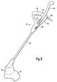
- the second handle 18 can be pivoted about the spindle 19 into the second position shown in Figs. 2 and 4 where it is generally aligned with the shaft 12 but disposed transverse to the first handle 14. In this second position the crosspiece 18c of the handle 18 forms a wrist and/or forearm backing support for a user grasping the first handle 14 with one hand.
- the user is able to apply additional leverage in a direction tending to lift the trimmer clear of the ground.
- a locking mechanism for locking the second handle 18 in any desired position is illustrated.
- the second handle 18 is secured to the first handle 14 by a cam-lock mechanism 25.
- This consists of a cam-lock lever 20 pivotally connected at one end of the spindle 19.
- the spindle 19 is first inserted through aligned openings in the two handles and secured with a nut 23.
- the cam-lock lever 20 With the cam-lock lever 20 in its locked position within the recessed portion 21 of the second handle arm 18a, the two side arms 18a, 18b of the second handle are urged inwardly against the opposite sides of the first handle 14 and relative rotation is prevented by interlocking the opposing faces of the two handles.
- the respective faces 31a, 31b of the side arms 18a, 18b each have a pair of perpendicular grooves 29 (Fig. 8) which engage with respective pairs of diametrically opposed teeth 28 angularly disposed around the central opening 27 for the spindle 19 in the opposing face 14b of the first handle 14.
- the second handle can be locked in a number of alternative positions in increments corresponding to the angular spacing of the teeth 28.
- the interlock is released by rotating the cam-lock lever 20 anti-clockwise about its pivot 30 from the position shown in Fig. 6 to the position shown in Fig. 7. Because the distance 'y' is less than the distance 'x' on the cam-lock lever, the second handle 18 is able to spring apart from the first handle 14 and clear of the interlocking teeth. The handle 18 can then be pivoted back from the position shown in full outline in Fig. 5 to the position shown in dashed outline or to any other position in which the teeth 28 mesh with the grooves 29 when the cam-lock lever is returned to its locked position shown in Fig. 6. For example, the handle 18 may be rotated beyond the position shown in dashed outline to a position at the rear of the shaft 12. This has the advantage that the tool can then be used for edging a lawn as well as for trimming.
Landscapes
- Life Sciences & Earth Sciences (AREA)
- Environmental Sciences (AREA)
- Engineering & Computer Science (AREA)
- Mechanical Engineering (AREA)
- Harvester Elements (AREA)
Applications Claiming Priority (2)
| Application Number | Priority Date | Filing Date | Title |
|---|---|---|---|
| GB9901056 | 1999-01-18 | ||
| GBGB9901056.3A GB9901056D0 (en) | 1999-01-18 | 1999-01-18 | Trimmer handle |
Publications (2)
| Publication Number | Publication Date |
|---|---|
| EP1020257A1 true EP1020257A1 (de) | 2000-07-19 |
| EP1020257B1 EP1020257B1 (de) | 2003-10-08 |
Family
ID=10846075
Family Applications (1)
| Application Number | Title | Priority Date | Filing Date |
|---|---|---|---|
| EP00300298A Expired - Lifetime EP1020257B1 (de) | 1999-01-18 | 2000-01-17 | Griff für Mähgerät |
Country Status (4)
| Country | Link |
|---|---|
| US (1) | US6327781B1 (de) |
| EP (1) | EP1020257B1 (de) |
| DE (1) | DE60005718T2 (de) |
| GB (1) | GB9901056D0 (de) |
Cited By (7)
| Publication number | Priority date | Publication date | Assignee | Title |
|---|---|---|---|---|
| WO2001070466A1 (de) * | 2000-03-23 | 2001-09-27 | Coronet-Werke Gmbh | Arbeitsgerät, insbesondere reinigungs- und applikationsgerät, mit einem stiel und einem griffelement |
| EP1327502A2 (de) * | 2002-01-10 | 2003-07-16 | Electrolux Home Products, Inc. | Faltbarer quergerichteter Handgriff für langes Werkzeug |
| EP1400319A1 (de) * | 2002-06-19 | 2004-03-24 | Black & Decker Inc. | Kraftwerkzeug |
| EP1504655A1 (de) * | 2003-08-04 | 2005-02-09 | BLACK & DECKER INC. | Griffanordnung für ein Kraftwerkzeug |
| EP1504657A1 (de) * | 2003-08-04 | 2005-02-09 | BLACK & DECKER INC. | Griffanordnung für ein Kraftwerkzeug |
| EP1504658A1 (de) * | 2003-08-04 | 2005-02-09 | BLACK & DECKER INC. | Schwenkbare Griffanordnung für ein Kraftwerkzeug |
| EP1504654A1 (de) * | 2003-08-04 | 2005-02-09 | BLACK & DECKER INC. | Griffanordnung für ein Kraftwerkzeug |
Families Citing this family (16)
| Publication number | Priority date | Publication date | Assignee | Title |
|---|---|---|---|---|
| EP1210858B1 (de) | 2000-11-29 | 2006-12-20 | Black & Decker Inc. | Pflanzenschutzvorrichtung |
| EP1210859A1 (de) | 2000-11-29 | 2002-06-05 | Black & Decker Inc. | Pflanzenschutzvorrichtung |
| US6973728B2 (en) * | 2002-04-04 | 2005-12-13 | The Toro Company | Filament trimmer with dual triggers |
| US7314096B2 (en) * | 2004-10-27 | 2008-01-01 | The Toro Company | Adjustable handle for portable tool |
| US7257909B2 (en) * | 2004-10-27 | 2007-08-21 | The Toro Company | Convertible yard tool |
| US20060123635A1 (en) * | 2004-12-09 | 2006-06-15 | Heow, Inc. | Combination blower, trimmer and edger for tending vegetation |
| US7547167B2 (en) | 2005-09-16 | 2009-06-16 | Robert Bosch Gmbh | Storage drawer for hand-held power tool |
| US7261166B2 (en) * | 2005-09-16 | 2007-08-28 | Robert Bosch Gmbh | Switch for power tool |
| US7424768B2 (en) * | 2005-09-16 | 2008-09-16 | Credo Technology Corporation | Handle for power tool |
| CN1934928B (zh) * | 2005-09-23 | 2011-09-07 | 苏州宝时得电动工具有限公司 | 手持式工具 |
| US8042220B2 (en) | 2005-09-28 | 2011-10-25 | Andreas Stihl Ag & Co. Kg | Implement |
| DE102005046227B4 (de) * | 2005-09-28 | 2009-10-01 | Andreas Stihl Ag & Co. Kg | Arbeitsgerät mit Einhand- und Zeihandbedienung |
| US7739800B2 (en) * | 2006-10-24 | 2010-06-22 | Hurley Edward P | Combination blower, trimmer and edger for tending vegetation |
| CN107094420A (zh) * | 2016-02-23 | 2017-08-29 | 苏州宝时得电动工具有限公司 | 打草机 |
| CN108718657B (zh) * | 2017-04-20 | 2021-08-10 | 苏州宝时得电动工具有限公司 | 打草机 |
| US11252868B2 (en) * | 2019-09-27 | 2022-02-22 | Tree Well Wizard, LLC | Landscape trimming tool attachment device |
Citations (2)
| Publication number | Priority date | Publication date | Assignee | Title |
|---|---|---|---|---|
| EP0653364A2 (de) * | 1993-11-09 | 1995-05-17 | Black & Decker Inc. | Verbesserte Stielzusammensetzung |
| EP0811312A1 (de) * | 1996-06-05 | 1997-12-10 | GARDENA Kress + Kastner GmbH | Arbeitsgerät, insbesondere Freischneide-Gerät |
Family Cites Families (2)
| Publication number | Priority date | Publication date | Assignee | Title |
|---|---|---|---|---|
| GB8714817D0 (en) * | 1987-06-24 | 1987-07-29 | Flymo Ltd | Grass trimmer |
| US5474350A (en) * | 1993-11-02 | 1995-12-12 | Gauthier; Serge | Auxiliary Shaft having a ball-shaped end releasably mounted in a two-part sleeve, for hand tools |
-
1999
- 1999-01-18 GB GBGB9901056.3A patent/GB9901056D0/en not_active Ceased
-
2000
- 2000-01-14 US US09/482,341 patent/US6327781B1/en not_active Expired - Fee Related
- 2000-01-17 DE DE60005718T patent/DE60005718T2/de not_active Expired - Lifetime
- 2000-01-17 EP EP00300298A patent/EP1020257B1/de not_active Expired - Lifetime
Patent Citations (2)
| Publication number | Priority date | Publication date | Assignee | Title |
|---|---|---|---|---|
| EP0653364A2 (de) * | 1993-11-09 | 1995-05-17 | Black & Decker Inc. | Verbesserte Stielzusammensetzung |
| EP0811312A1 (de) * | 1996-06-05 | 1997-12-10 | GARDENA Kress + Kastner GmbH | Arbeitsgerät, insbesondere Freischneide-Gerät |
Cited By (19)
| Publication number | Priority date | Publication date | Assignee | Title |
|---|---|---|---|---|
| WO2001070466A1 (de) * | 2000-03-23 | 2001-09-27 | Coronet-Werke Gmbh | Arbeitsgerät, insbesondere reinigungs- und applikationsgerät, mit einem stiel und einem griffelement |
| EP1327502A2 (de) * | 2002-01-10 | 2003-07-16 | Electrolux Home Products, Inc. | Faltbarer quergerichteter Handgriff für langes Werkzeug |
| EP1327502A3 (de) * | 2002-01-10 | 2005-10-26 | Electrolux Home Products, Inc. | Faltbarer quergerichteter Handgriff für langes Werkzeug |
| EP1808274A1 (de) * | 2002-06-19 | 2007-07-18 | Black & Decker, Inc. | Kraftwerkzeug |
| EP1400319A1 (de) * | 2002-06-19 | 2004-03-24 | Black & Decker Inc. | Kraftwerkzeug |
| AU2008207516B2 (en) * | 2002-06-19 | 2010-07-29 | Black & Decker Inc. | Power tool |
| EP2047954A1 (de) | 2002-06-19 | 2009-04-15 | Black & Decker, Inc. | Kraftwerkzeug |
| AU2003204753B2 (en) * | 2002-06-19 | 2008-10-30 | Black & Decker, Inc. | Power tool |
| US7178248B2 (en) | 2002-06-19 | 2007-02-20 | Black & Decker Inc. | Power tool |
| EP1504657A1 (de) * | 2003-08-04 | 2005-02-09 | BLACK & DECKER INC. | Griffanordnung für ein Kraftwerkzeug |
| CN1324944C (zh) * | 2003-08-04 | 2007-07-11 | 百得有限公司 | 用于电动工具的把手组件及包含此把手组件的电动工具 |
| CN100338992C (zh) * | 2003-08-04 | 2007-09-26 | 百得有限公司 | 用于电动工具的把手组件及具有把手组件的电动工具 |
| US7275322B2 (en) | 2003-08-04 | 2007-10-02 | Black & Decker Inc. | Pivoting handle assembly for power tool |
| CN100381038C (zh) * | 2003-08-04 | 2008-04-16 | 百得有限公司 | 具有枢转把手组件的电动工具 |
| EP1504654A1 (de) * | 2003-08-04 | 2005-02-09 | BLACK & DECKER INC. | Griffanordnung für ein Kraftwerkzeug |
| EP1504658A1 (de) * | 2003-08-04 | 2005-02-09 | BLACK & DECKER INC. | Schwenkbare Griffanordnung für ein Kraftwerkzeug |
| EP1504655A1 (de) * | 2003-08-04 | 2005-02-09 | BLACK & DECKER INC. | Griffanordnung für ein Kraftwerkzeug |
| US8336213B2 (en) | 2003-08-04 | 2012-12-25 | Black & Decker Inc. | Handle assembly for power tool |
| US8347510B2 (en) | 2003-08-04 | 2013-01-08 | Black & Decker Inc. | Handle assembly for power tool |
Also Published As
| Publication number | Publication date |
|---|---|
| GB9901056D0 (en) | 1999-03-10 |
| DE60005718T2 (de) | 2004-08-12 |
| DE60005718D1 (de) | 2003-11-13 |
| US6327781B1 (en) | 2001-12-11 |
| EP1020257B1 (de) | 2003-10-08 |
Similar Documents
| Publication | Publication Date | Title |
|---|---|---|
| EP1020257B1 (de) | Griff für Mähgerät | |
| EP2061632B1 (de) | Tragbares elektrowerkzeug | |
| US4829755A (en) | Trimmer wheels | |
| US6260278B1 (en) | Hand-held lawn and brush trimmer having manual trimmer head adjustment mechanisms | |
| US7131499B2 (en) | Combination line trimmer and edger | |
| CN201830692U (zh) | 具有可旋转的后部把手的绿篱修剪器 | |
| CN112470737A (zh) | 带有刀具的手操纵式工作器械 | |
| EP2050327A1 (de) | Buschschneider | |
| EP3669628B1 (de) | Gartenwerkzeug und steuerkasten dafür | |
| EP3282826B1 (de) | Schnitthöheneinstellung für rasenmäher | |
| KR101067518B1 (ko) | 예초기 | |
| AU2004201628A1 (en) | Ergonomic handle for vegetation trimmer | |
| US20090188354A1 (en) | Combination Vegetation trimmer and edger | |
| WO2011113445A1 (en) | Tools | |
| US20240081192A1 (en) | Hedge trimmer | |
| CN201075905Y (zh) | 打草机 | |
| CN112004405B (zh) | 手持式工具机、尤其是打草机或者割灌机 | |
| CN220359735U (zh) | 杆类工具 | |
| JP3805976B2 (ja) | ヘッジトリマ | |
| CN113950241B (zh) | 电动耕耘机 | |
| CN112004402B (zh) | 手持式工具机、尤其是园艺器具 | |
| CN112004403B (zh) | 呈打草机或者割灌机形式的手持式工具机 | |
| EP1356722A1 (de) | Fadenschneider | |
| EP1468597A1 (de) | Ergonomische Handgriffanordnung für Pflanzentrimmer | |
| JP3171105U (ja) | 草飛散防止カバー付き草刈機 |
Legal Events
| Date | Code | Title | Description |
|---|---|---|---|
| PUAI | Public reference made under article 153(3) epc to a published international application that has entered the european phase |
Free format text: ORIGINAL CODE: 0009012 |
|
| AK | Designated contracting states |
Kind code of ref document: A1 Designated state(s): DE FR GB IT |
|
| AX | Request for extension of the european patent |
Free format text: AL;LT;LV;MK;RO;SI |
|
| 17P | Request for examination filed |
Effective date: 20001221 |
|
| AKX | Designation fees paid |
Free format text: DE FR GB IT |
|
| GRAH | Despatch of communication of intention to grant a patent |
Free format text: ORIGINAL CODE: EPIDOS IGRA |
|
| GRAS | Grant fee paid |
Free format text: ORIGINAL CODE: EPIDOSNIGR3 |
|
| GRAA | (expected) grant |
Free format text: ORIGINAL CODE: 0009210 |
|
| AK | Designated contracting states |
Kind code of ref document: B1 Designated state(s): DE FR GB IT |
|
| PG25 | Lapsed in a contracting state [announced via postgrant information from national office to epo] |
Ref country code: IT Free format text: LAPSE BECAUSE OF FAILURE TO SUBMIT A TRANSLATION OF THE DESCRIPTION OR TO PAY THE FEE WITHIN THE PRESCRIBED TIME-LIMIT;WARNING: LAPSES OF ITALIAN PATENTS WITH EFFECTIVE DATE BEFORE 2007 MAY HAVE OCCURRED AT ANY TIME BEFORE 2007. THE CORRECT EFFECTIVE DATE MAY BE DIFFERENT FROM THE ONE RECORDED. Effective date: 20031008 |
|
| REG | Reference to a national code |
Ref country code: GB Ref legal event code: FG4D |
|
| REF | Corresponds to: |
Ref document number: 60005718 Country of ref document: DE Date of ref document: 20031113 Kind code of ref document: P |
|
| ET | Fr: translation filed | ||
| PLBE | No opposition filed within time limit |
Free format text: ORIGINAL CODE: 0009261 |
|
| STAA | Information on the status of an ep patent application or granted ep patent |
Free format text: STATUS: NO OPPOSITION FILED WITHIN TIME LIMIT |
|
| 26N | No opposition filed |
Effective date: 20040709 |
|
| PGFP | Annual fee paid to national office [announced via postgrant information from national office to epo] |
Ref country code: GB Payment date: 20130122 Year of fee payment: 14 Ref country code: FR Payment date: 20130207 Year of fee payment: 14 |
|
| REG | Reference to a national code |
Ref country code: DE Ref legal event code: R084 Ref document number: 60005718 Country of ref document: DE Effective date: 20130603 |
|
| GBPC | Gb: european patent ceased through non-payment of renewal fee |
Effective date: 20140117 |
|
| REG | Reference to a national code |
Ref country code: FR Ref legal event code: ST Effective date: 20140930 |
|
| PG25 | Lapsed in a contracting state [announced via postgrant information from national office to epo] |
Ref country code: FR Free format text: LAPSE BECAUSE OF NON-PAYMENT OF DUE FEES Effective date: 20140131 Ref country code: GB Free format text: LAPSE BECAUSE OF NON-PAYMENT OF DUE FEES Effective date: 20140117 |
|
| PGFP | Annual fee paid to national office [announced via postgrant information from national office to epo] |
Ref country code: DE Payment date: 20190326 Year of fee payment: 20 |
|
| PGFP | Annual fee paid to national office [announced via postgrant information from national office to epo] |
Ref country code: DE Payment date: 20190326 Year of fee payment: 20 |
|
| REG | Reference to a national code |
Ref country code: DE Ref legal event code: R071 Ref document number: 60005718 Country of ref document: DE |