EP1504655A1 - Griffanordnung für ein Kraftwerkzeug - Google Patents
Griffanordnung für ein Kraftwerkzeug Download PDFInfo
- Publication number
- EP1504655A1 EP1504655A1 EP04015196A EP04015196A EP1504655A1 EP 1504655 A1 EP1504655 A1 EP 1504655A1 EP 04015196 A EP04015196 A EP 04015196A EP 04015196 A EP04015196 A EP 04015196A EP 1504655 A1 EP1504655 A1 EP 1504655A1
- Authority
- EP
- European Patent Office
- Prior art keywords
- handle
- housing
- hedge trimmer
- user
- handle assembly
- Prior art date
- Legal status (The legal status is an assumption and is not a legal conclusion. Google has not performed a legal analysis and makes no representation as to the accuracy of the status listed.)
- Granted
Links
Images


Classifications
-
- H—ELECTRICITY
- H01—ELECTRIC ELEMENTS
- H01H—ELECTRIC SWITCHES; RELAYS; SELECTORS; EMERGENCY PROTECTIVE DEVICES
- H01H3/00—Mechanisms for operating contacts
- H01H3/32—Driving mechanisms, i.e. for transmitting driving force to the contacts
- H01H3/36—Driving mechanisms, i.e. for transmitting driving force to the contacts using belt, chain, or cord
-
- A—HUMAN NECESSITIES
- A01—AGRICULTURE; FORESTRY; ANIMAL HUSBANDRY; HUNTING; TRAPPING; FISHING
- A01G—HORTICULTURE; CULTIVATION OF VEGETABLES, FLOWERS, RICE, FRUIT, VINES, HOPS OR SEAWEED; FORESTRY; WATERING
- A01G3/00—Cutting implements specially adapted for horticultural purposes; Delimbing standing trees
- A01G3/04—Apparatus for trimming hedges, e.g. hedge shears
- A01G3/047—Apparatus for trimming hedges, e.g. hedge shears portable
- A01G3/053—Apparatus for trimming hedges, e.g. hedge shears portable motor-driven
-
- H—ELECTRICITY
- H01—ELECTRIC ELEMENTS
- H01H—ELECTRIC SWITCHES; RELAYS; SELECTORS; EMERGENCY PROTECTIVE DEVICES
- H01H9/00—Details of switching devices, not covered by groups H01H1/00 - H01H7/00
- H01H9/02—Bases, casings, or covers
- H01H9/06—Casing of switch constituted by a handle serving a purpose other than the actuation of the switch, e.g. by the handle of a vacuum cleaner
Definitions
- the present invention relates to a handle assembly for a power tool, and to a power tool incorporating such an assembly.
- the invention relates particularly, but not exclusively, to a handle assembly for a hedge trimmer, and a hedge trimmer incorporating such a mechanism.
- Hedge trimmers are power tools for general garden use with an axially reciprocating blade comprising a plurality of teeth disposed adjacent a stationary blade, the teeth of the stationary blade providing a reaction force for the teeth of the reciprocating blade.
- a hedge trimmer is easier to manipulate when held with both hands than when held with one hand. This provides the user with greater control over the hedge trimmer and therefore facilitates more accurate cutting.
- a two handed grip is a safety feature. It is significantly easier to lose control of a hedge trimmer when holding it with one hand, and therefore a two handed grip allows much safer use of the hedge trimmer.
- a known hedge trimmer supplied by Flymo SA, for example under the trade mark FLYMO EASI-TRIM EHT 420, has a handle assembly in which front and rear handles are formed as opposite sides of a generally symmetrical loop.
- This known hedge trimmer suffers from the drawback that as the front handle is angled forwardly (i.e. the front handle makes an acute angle with the blade assembly), there is a limit to the size of the front handle, as the front handle will eventually come into contact with the hedge trimmer hand guard.
- Preferred embodiments of the present invention seek to overcome the above disadvantage of the prior art.
- a handle assembly for a power tool having a housing, a motor provided in the housing, and an output shaft adapted to be caused by said motor to actuate a working member extending from the housing along a first axis, the handle assembly comprising:-
- the front handle and rear handles may be oriented to enable a user to grip the front handle with a first hand and the rear handle with a second hand such that the axes of the user's wrists are substantially parallel to one another.
- This provides the advantage that the user can hold the tool with the blade in any orientation without having to twist one wrist relative to the other, thereby making holding of the hedge trimmer more comfortable, and minimising the application of undesirable torque to the tool.
- Said front and rear handles may define a continuous loop.
- the power tool may further comprise first switching means provided on said front handle, and second switching means formed on said rear handle, wherein said power tool is operable on actuation of both first and second switching means.
- Said power tool may be a hedge trimmer.
- a power tool having a housing, a motor provided in the housing , an output shaft adapted to be caused by said motor to actuate a working member extending from the housing along a first axis, and a handle assembly as defined above.
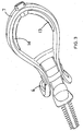
- a hedge trimmer (1) comprises a handle assembly (2) formed from durable plastics material pivotably connected to a housing (3).
- a guard (4) is formed integrally with the housing (3) and an electric motor (not shown) is disposed axially within the housing (3) such that the axis of rotation of an output shaft (not shown) of the motor is generally parallel to the direction of reciprocating motion of a blade assembly (5).
- the blade assembly (5) extends forwardly of the housing (3).
- the electric motor (not shown) is connected to the blade assembly via a drive conversion mechanism, the operation of which will be described in further detail below.
- the blade assembly (5) comprises a stationary blade disposed adjacent to a blade adapted to execute reciprocating movement along a longitudinal axis of the stationary blade. In this way, the stationary blade provides a reaction force for the reciprocating blade to grip against and cut.
- the operation of this type of blade assembly is well known in the art and will not be described in any further detail herein.
- the handle assembly (2) comprises a forward handle (6) and a rear handle (7).
- Both forward and rear handles (6), (7) are formed integrally from moulded durable plastics and enable a user to hold the hedge trimmer in a variety of ways.
- a two-handle assembly has two advantages. Firstly, when the tool is gripped in both hands it is more stable in the user's hands and therefore easier to control, which enables more accurate and precise cutting.
- a two-handed grip on the hedge trimmer is a lot safer than a single handed grip. It is a lot easier for a user to lose control of a hedge trimmer when gripping it with only one hand.
- the hedge trimmer is provided with a dual switching mechanism.
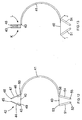
- the user In order to activate the hedge trimmer, the user must simultaneously depress a forward switch (8) and either one of rear switches (13), (14), as shown in Figure 3. As a result, it is impossible for the user to activate the hedge trimmer without first gripping it with both hands.
- the present invention provides a handle assembly which allows a left-handed user and a right-handed user to operate the hedge trimmer in any orientation with the wrists of each arm aligned, i.e. with the wrists arranged along parallel axes.
- the right-handed user would grip forward handle (6) with his left hand such that the fingers of his left hand pass around the front of forward handle (6) and grip switch (8) with the fingertips of his left hand.
- the right-handed user would place his right hand around rear handle (7) such that the fingertips of his right hand grip switch (13).
- This feature of the present invention offers several advantages over the prior art. Firstly, holding the hedge trimmer without a twist in the user's arm is more comfortable, and affords the user more control over the hedge trimmer blade. Secondly, prior art hedge trimmers must be held with a twist in the user's arm. Over prolonged periods of use, the user's arms may tire, and apply an unwanted torque to the hedge trimmer as the muscles of the user's forearms attempt to orientate themselves into a more comfortable position. This makes it more difficult to accurately cut with the hedge trimmer.
- line A-A represents the plane of blade assembly (5).
- the plane of rear handle (7) is at an angle to line A-A such that the rear part of rear handle (7) is raised substantially away from the plane of blade (5).
- the knuckles of the hand of the user that is gripping rear handle (7) are raised away from the surface of the hedge being cut. This provides the advantage that the user's knuckles avoid any grazing or cutting resulting from contact with the hedge, or with the ground when carrying out low cutting.
- FIG. 6 a second embodiment of the handle assembly (102) is shown. It can be seen that front handle (106) is swept back at a greater angle relative to the plane of the blade compared with the angle of front handle (6) relative to the plane of blade (5) as shown in Figure 5.
- This feature makes the hedge trimmer more comfortable for the user to operate provided that the centre of mass of the hedge trimmer lies in the region between front handle (106) and rear handle (107) which will usually be the case, since the heaviest parts of the hedge trimmer are generally the blade and the motor housing. The user does not have to stretch his forward arm as far relative to the rear handle as he would do when using the handle assembly shown in Figure 5.
- the rear handle located as far away from the centre of mass as is possible. Since the two heaviest components of a hedge trimmer are generally the electric motor disposed in the housing and the forward blade assembly, the centre of mass of the hedge trimmer generally lies between the motor and the blade.
- the rear handle (7), (107) In order to make the hedge trimmer easier to manipulate, it is desirable to locate the rear handle (7), (107) as far away from the centre of mass as possible. This is because the further away the rear handle is from the centre of mass, the less force is needed to be applied to the rear handle to apply the same torque to the hedge trimmer.
- One way of achieving this is to make the rear handle as large as possible without increasing the weight of the rear handle, and for this reason the rear handle (7), (107) of the hedge trimmer is formed into the curved bar loop shape with a space enclosed as is best shown in Figure 2 or in Figure 6.
- the handle assembly (7) of the present invention enables the user to operate the hedge trimmer for cutting a horizontal surface such that the wrists of the user's arms are oriented generally parallel to one another. Also, as described above, when the blade is required to be operated in the vertical plane, the user can operate the hedge trimmer with his wrists arranged in generally parallel vertical planes.
- the user is holding the hedge trimmer high up relative to his body or even holding the hedge trimmer above his head in order to cut a horizontal surface, the user is less stable than he would be were he operating the hedge trimmer further down relative to his body.
- hedge trimmers can generally be operated upside down, it has been found that consumers are generally very reluctant to operate hedge trimmers upside down whilst held above the head.
- the hedge trimmer is shown without the forwardly projecting blade where the body housing (3) has been pivoted relative to the handle assembly (2).
- the hedge trimmer is operated in exactly the same way as before, with the user gripping both forward and rear handles and depressing forward and rear switches respectively.
- This feature makes it easier for the user to view along the plane of the blade when cutting the top of a tall hedge, and more comfortable for horizontal cutting in a position high up relative to the user's body. This is because instead of the user having to hold the handles horizontally at eye level as with prior art hedge trimmers, the user can now hold the handle assembly in front of his body whilst looking along the plane of the blade.
- a first retaining member (81) is mounted at a first end of a bracket (85), and the other end of bracket (85) is mounted on a compression spring (86). Compression spring (86) is fixed to the body of the hedge trimmer housing at (87).
- a second retaining member (82) is able to pivot about a pin (88), pin (88) being fixed relative to the housing (3). Second retaining member (82) is also rigidly fixed to a first end of a lever (89), the second end of lever (89) being slidable in a second bracket (90), second bracket (90) being formed in first bracket (85).
- either the first or second retaining means (81, 82) will engage with a corresponding portion of the handle assembly (not shown), and a user would release the mechanism simply by pushing the retaining member which is not in engagement with the handle assembly back into the housing, as this action would also result in retracting the other retaining member from engagement with the handle assembly.
- the hedge trimmer housing (3) engages the hedge trimmer handle assembly at a cylindrical pivot (80) such that the housing (3) can rotate about pivot portion (80).
- the hedge trimmer can be operated in two separate orientations, the in-line orientation as shown in Figure 2, or the orientation shown in Figures 8 and 9 where the hedge trimmer housing (3) is rotated through 90° relative to the hedge trimmer handle assembly (2).
- the housing (3) In order to retain the hedge trimmer housing (3) in position relative to the handle assembly (not shown), the housing (3) is provided with a first retaining member (81) and a second retaining member (82). Both first and second retaining members (81, 82) are retractable relative to the housing (3), and are shown in their respective retracted positions in Figure 17a.
- the rear end of housing (3) has an integrally formed abutment surface (83) shaped to receive an engaging portion (84) of handle assembly (2). It can be seen that the engaging portion (84) of the handle assembly is received between abutment surface (83) of the housing (3) and the first retaining member (81) such that the engaging portion (84) can not move in either the upwards or downwards direction relative to housing (3).
- the first retaining member (81) is so shaped that the engaging portion (84) can slide into engagement with abutment surface (83) by displacing retaining member (81), but cannot move out of engagement with abutment surface (83) until retaining member (81) is retracted into the housing (3).
- first retaining member (82) grips a second engaging portion (not shown) of the handle assembly, and in this orientation even though first retaining member (81) is deployed, it is not in use.
- first or second retaining members (81, 82) can be depressed by the user, depending on which one is not in engagement with the handle assembly, which simultaneously moves both first and second retaining members (81, 82) into the housing.
- a bowden cable such as that used to operate the brakes on a pedal bicycle, consists of an inner cable (40) surrounded by an outer sheath (41).
- the inner cable (40) passes through the outer cable (41) and is slidable relative thereto.
- An electrical contact shown generally by (42) comprises a first metallic pad (43) mounted on an arm (44), the arm being pivotable about point (45) and a second metallic pad (46) mounted on a second arm (47), the second arm being pivotable about point 48 such that metallic pads (43) and (46) can be pivoted towards each other, and into contact.
- a first end of inner cable (40) is attached to metallic pad (43) at point (49), and a first end of outer cable (41) is attached to arm (47) at point (50).
- a first switch (51) comprises an arm that is pivotable about point (52), the arm being attached to a second end of inner cable (40) at point (53).
- a second switch (54) is pivotable about point (55) and is attached to the outer cable at point (56).
- first switch (51) and second switch (54) are operated by a user applying pressure and pivoting them away from each other in the direction shown by arrows I and J.
- first switch (51) is rigidly attached to the inner cable (40)
- second switch (54) is rigidly attached to the outer cable (41)
- the pivoting motion of the switches in opposite directions draws the inner cable (40) through outer cable (41)
- second switch (54) pushes outer cable (41) around inner cable (40).
- inner cable (40) pulls first metallic pad (43) in the direction of arrow K
- outer cable (41) pushes the second metallic pad (46) in the direction of arrow L such that pads (43), (46) come into contact.
- a switching mechanism of this type is possible with more than two switches.
- a single inner cable (40) can be provided with a plurality of outer sheaths (41), each outer sheath moving independently of one another which provides the option of adding more switches and/or electrical contacts.
- the mechanism will be set up such that closing one switch will have the result of partially closing the contact by more than half the distance required to fully close the contact, and closing the second switch will also have the result of more than half closing the contact. In this way, it is ensured that the contact will actually be closed when both switches are closed.
- Figures 12 and 13 are only a schematic representation of the switching mechanism, and in practise the contacts be in the form of something other than pivoting metallic pads, as will be described below.
- a pin (61) is held in a pin housing (62) which is disposed in the hedge trimmer handle assembly (not shown).
- the pin (61) and pin housing (62) are slidable relative to the hedge trimmer handle assembly (not shown) in the direction of arrow M.
- Pin (61) projects outwardly from housing (62) and is received in an aperture (68) formed in an arm member (63).
- Arm member (63) is mounted to the hedge trimmer body housing (not shown) by a pin (64). Arm member (63) is pivotable about pin (64) in the direction of arrow N relative to the hedge trimmer housing (not shown).
- An electrical relay (65) is disposed in the hedge trimmer housing (not shown) such that when arm (63) is pivoted in the direction of arrow N, a remote end (66) of arm (63) depresses a switch (67) and closes relay (65).
- first and second hedge trimmer switches which in the embodiment of the hedge trimmer shown in Figure 4 for example, would be switch (8) formed on front handle (6) and either one of switches (13), (14) formed on rear handle (7).
- the hedge trimmer body housing (3) can be pivoted at 90 ⁇ relative to the handle assembly (2).
- the pin housing (62) is rotated through 90 ⁇ from the position shown in Figure 14a.
- Pin (61) now abuts third cam surface (71), and as the hedge trimmer housing has remained stationary, arm member (63) remains in the same position.
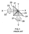
- an electric motor (14) is disposed axially in housing (3), such that the axis of rotation (15) of the motor output shaft (16) is parallel to the plane of blade (5). It can be seen therefore that in order to drive the blade mechanism, the direction of rotation about axis (15) needs to be converted through 90° into rotation about axis (17).
- the drive conversion mechanism of the present invention for converting rotation about a first axis to rotation about a second axis comprises a shaft (30) rotating in the direction of arrow (31).
- a plurality of axially aligned parallel teeth (32) are formed at the end of shaft (30).
- Parallel teeth (32) intermesh with a second plurality of radial teeth (33) formed on the upper surface of a gear plate (34).
- Gear plate (34) is mounted on a second shaft (35) such that gear plate (34) is free to rotate about an axis Z-Z.
- the rotation of shaft (30) imparts rotation to gear plate (35) in the direction of arrow (36) due to the reaction between teeth (32) and teeth (33).
- This method of converting rotation about a first axis into rotation about a second axis generally perpendicular to said first axis is substantially cheaper to manufacture than prior art methods, as the engineering tolerances between teeth (32) and shaft (30) and teeth (33) on the gear plate (34) can be less than those needed to be achieved with the conical gears of the prior art drive mechanisms.
- An electric motor drives a rotary output shaft (16) adapted to rotate about axis (15).
- a plurality of teeth (40) are formed on the edge of shaft (16) and intermesh with a second plurality of teeth (41) formed on a gear (42).
- Gear (42) is adapted to rotate about axis (18) which is parallel to axis (15), and as gear (42) comprises a larger number of teeth (41) than the number of teeth (40) formed on output shaft (16), the rotational speed of gear (42) is less than that of output shaft (16).
- Gear (42) is mounted on a shaft (30) which has a further set of teeth (32) formed around the edge of shaft (30). Teeth (32) intermesh with a plurality of radial teeth (33) formed on the upper surface of a gear plate (34).
- Gear plate (34) is mounted on shaft (35) and adapted to rotate about axis (17) such that the rotation of shaft (30) about axis (18) is converted to rotation about axis (17) generally perpendicular to axis (18).
- the teeth on shaft (32) can still drive gear plate (34) despite variations in position between the shaft and the gear plate, provided the teeth on the shaft still engage the teeth on the gear plate.
- the shaft and gear plate therefore do not need to be as accurately located relative to each other as the bevel gears of the prior art.
- the inline rotation of the motor output shaft (16) is converted into rotation in the plane of blade (5).
- the blade (5) is connected to gear plate (34) via a drive conversion mechanism for converting rotary motion about axis (17) into linear reciprocating motion perpendicular to axis (17) in a manner which will be familiar to persons skilled in the art, such as a scotch yoke mechanism. Mechanisms of this type are well known in the art and will not be described herein in any further detail.
Landscapes
- Life Sciences & Earth Sciences (AREA)
- Biodiversity & Conservation Biology (AREA)
- Ecology (AREA)
- Forests & Forestry (AREA)
- Environmental Sciences (AREA)
- Harvester Elements (AREA)
- Sawing (AREA)
- Details Of Spanners, Wrenches, And Screw Drivers And Accessories (AREA)
Applications Claiming Priority (6)
| Application Number | Priority Date | Filing Date | Title |
|---|---|---|---|
| GB0318150 | 2003-08-04 | ||
| GB0318150A GB2404550A (en) | 2003-08-04 | 2003-08-04 | Latch mechanism for pivoting handle assembly of a power tool |
| GB0318751A GB2404832A (en) | 2003-08-09 | 2003-08-09 | Safety mechanism for power tool |
| GB0318751 | 2003-08-09 | ||
| GB0410917A GB2404554A (en) | 2003-08-04 | 2004-05-17 | Handle assembly for a power tool |
| GB0410917 | 2004-05-17 |
Publications (2)
| Publication Number | Publication Date |
|---|---|
| EP1504655A1 true EP1504655A1 (de) | 2005-02-09 |
| EP1504655B1 EP1504655B1 (de) | 2006-08-16 |
Family
ID=33556056
Family Applications (1)
| Application Number | Title | Priority Date | Filing Date |
|---|---|---|---|
| EP04015196A Not-in-force EP1504655B1 (de) | 2003-08-04 | 2004-06-29 | Griffanordnung für ein Kraftwerkzeug |
Country Status (8)
| Country | Link |
|---|---|
| US (1) | US8336213B2 (de) |
| EP (1) | EP1504655B1 (de) |
| CN (1) | CN1324944C (de) |
| AT (1) | ATE336162T1 (de) |
| AU (1) | AU2004203407A1 (de) |
| CA (1) | CA2476068C (de) |
| DE (1) | DE602004001941T2 (de) |
| NZ (1) | NZ534435A (de) |
Cited By (1)
| Publication number | Priority date | Publication date | Assignee | Title |
|---|---|---|---|---|
| EP2492070A1 (de) * | 2011-02-28 | 2012-08-29 | Zanon S.R.L. | Kettensäge, insbesondere zum Beschneiden von Bäumen und Büschen |
Families Citing this family (5)
| Publication number | Priority date | Publication date | Assignee | Title |
|---|---|---|---|---|
| US20080015688A1 (en) * | 2004-06-29 | 2008-01-17 | Micardia Corporation | Adjustable multi-segment cardiac valve implant with selective dimensional adjustment |
| EP2365502B1 (de) * | 2010-03-08 | 2014-09-17 | Robert Bosch GmbH | Elektrische Werkzeuge und Schaltgerät dafür |
| CN102933070B (zh) * | 2010-06-04 | 2015-05-20 | 胡斯华纳有限公司 | 用于手持式动力工具的把手系统 |
| US11806858B2 (en) * | 2017-09-27 | 2023-11-07 | Globe (jiangsu) Co., Ltd. | Impact protecting member for a cutting tool |
| EP3733352A1 (de) * | 2019-04-29 | 2020-11-04 | Hilti Aktiengesellschaft | Schutzvorrichtung für ein werkzeuggerät, sowie system, das eine schutzvorrichtung und ein werkzeuggerät umfasst |
Citations (5)
| Publication number | Priority date | Publication date | Assignee | Title |
|---|---|---|---|---|
| EP0214455A1 (de) * | 1985-08-30 | 1987-03-18 | GARDENA Kress + Kastner GmbH | Motorisch betriebenes Handgerät |
| DE19527207A1 (de) * | 1994-07-26 | 1996-02-01 | Atco Qualcast Ltd A British Co | Schalterbetätigungsorgan für elektrisch betriebene Werkzeuge |
| FR2738710A1 (fr) * | 1995-09-15 | 1997-03-21 | Lays Louis Gustave | Taille-haie a poignees multi-positions |
| EP1020257A1 (de) * | 1999-01-18 | 2000-07-19 | ROBERT BOSCH GmbH | Griff für Mähgerät |
| GB2384678A (en) * | 2002-01-31 | 2003-08-06 | Paul Nicholas Pacey Lockton | Hedge trimming and shaping device |
Family Cites Families (46)
| Publication number | Priority date | Publication date | Assignee | Title |
|---|---|---|---|---|
| US135628A (en) * | 1873-02-11 | Improvement in handles for saws | ||
| US1838690A (en) * | 1929-08-12 | 1931-12-29 | Lepiane Joe | Motor hedge trimmer |
| US1937586A (en) * | 1931-12-30 | 1933-12-05 | Elwood K Ortt | Hedge trimmer and the like |
| US1919516A (en) * | 1932-11-17 | 1933-07-25 | John Slaby | Hedge trimmer or clipper |
| US3050854A (en) * | 1961-01-12 | 1962-08-28 | Becker John | Rotary hedge trimmer |
| US3409056A (en) * | 1965-09-13 | 1968-11-05 | Stihl Maschf Andreas | Portable power chain saw |
| US3579827A (en) * | 1966-08-01 | 1971-05-25 | Sunbeam Corp | Hedge trimmer |
| US3962924A (en) * | 1974-04-24 | 1976-06-15 | The Black And Decker Manufacturing Company | Double cam drive for a hedge trimmer having two reciprocating cutting blades |
| US3909943A (en) * | 1974-08-19 | 1975-10-07 | Mc Graw Edison Co | Powered cutter with snubber drive means |
| US3902243A (en) * | 1974-11-04 | 1975-09-02 | Singer Co | Gear support for a hedge trimmer |
| US3991468A (en) * | 1975-10-10 | 1976-11-16 | Williams Marvin P | Hedge trimmer handle attachment |
| US4282652A (en) * | 1977-05-13 | 1981-08-11 | Emerson Electric Co. | Apparatus for cutting vegetation |
| US4145810A (en) * | 1977-09-02 | 1979-03-27 | Betty Hardman | Attachment for hedge trimmers |
| US4206657A (en) * | 1977-10-19 | 1980-06-10 | Black & Decker Inc. | Power driven tool having a reciprocating shaft arrangement and method of assembly |
| US4226021A (en) * | 1978-10-19 | 1980-10-07 | Hoffco, Inc. | Shaft assembly for lawn trimmer |
| GB2390324A (en) * | 2002-06-19 | 2004-01-07 | Black & Decker Inc | Power tool with pivoting handle |
| US4638562A (en) * | 1986-02-26 | 1987-01-27 | Tom Drake | Extension handles for hedge trimmers |
| US4651420A (en) * | 1986-05-22 | 1987-03-24 | Lonnecker Joseph C A | Universal vegetation cutter or UVC |
| SE460270B (sv) * | 1986-11-06 | 1989-09-25 | Electrolux Ab | Anordning vid motordrivna handredskap |
| EP0267973B1 (de) * | 1986-11-11 | 1992-02-12 | Black & Decker Inc. | Kraftgetriebene Säge, insbesondere elektromotorisch angetriebene Säge |
| US4787145A (en) * | 1987-03-09 | 1988-11-29 | Klicker Garry L | Two position portable power tool hanger stabilized by spring and detent |
| US4991298A (en) * | 1988-09-13 | 1991-02-12 | David K. Caruso | Extendible tree trimming apparatus |
| US4979306A (en) * | 1989-01-17 | 1990-12-25 | Kioritz Corporation | Power working machine |
| JPH0538574Y2 (de) * | 1989-01-30 | 1993-09-29 | ||
| DE3929441C2 (de) * | 1989-09-05 | 1998-09-10 | Stihl Maschf Andreas | Handgeführtes Arbeitsgerät |
| US5150523A (en) * | 1991-07-11 | 1992-09-29 | Ryobi Motor Products Corporation | Deadman switch arrangement for a hedge trimmer |
| DE4302676A1 (de) * | 1993-01-30 | 1994-08-04 | Bosch Gmbh Robert | Beidhändig geführtes Elektrohandwerkzeug mit Griffbügel |
| GB9412294D0 (en) | 1994-06-18 | 1994-08-10 | Black & Decker Inc | Improvements in cutting devices |
| US5531027A (en) * | 1994-07-21 | 1996-07-02 | Mcculloch Corporation | Hedge trimmer drive assembly |
| DE19640653A1 (de) | 1996-10-02 | 1998-04-09 | Gardena Kress & Kastner Gmbh | Motorbetriebene Heckenschere |
| JP3825136B2 (ja) * | 1997-05-14 | 2006-09-20 | 株式会社共立 | 手持ち式動力作業機 |
| US5882249A (en) * | 1997-11-10 | 1999-03-16 | Ferland; Marc | Concrete finishing machine |
| IT245050Y1 (it) | 1998-05-05 | 2002-03-19 | Valex Spa | Dispositivo perfezionato di azionamento e frenatura a doppio consenso,particolarmente per utensili motorizzati |
| USD434620S (en) * | 1999-06-23 | 2000-12-05 | The Toro Company | Housing for a hedge trimmer |
| US6324728B1 (en) * | 1999-10-18 | 2001-12-04 | Blankenheim Services, Llc | Ergonomic attachment for inline power tools |
| GB0005863D0 (en) | 2000-03-10 | 2000-05-03 | Bosch Gmbh Robert | Hedge cutter |
| US6439088B1 (en) * | 2000-04-25 | 2002-08-27 | The Toro Company | Reconfigurable vegetation trimmer and method of use |
| JP3622646B2 (ja) | 2000-08-22 | 2005-02-23 | 株式会社ムサシ | ヘッジトリマー |
| US6973728B2 (en) * | 2002-04-04 | 2005-12-13 | The Toro Company | Filament trimmer with dual triggers |
| USD505602S1 (en) * | 2002-11-14 | 2005-05-31 | Black & Decker, Inc. | Hedge trimmer |
| DE10260466B4 (de) | 2002-12-21 | 2014-07-03 | Andreas Stihl Ag & Co. Kg | Handgeführtes Arbeitsgerät |
| US20040128839A1 (en) * | 2003-01-06 | 2004-07-08 | Shaffer Chadwick A. | Snap-on and slidable assist handle for filament trimmer |
| CN2611099Y (zh) * | 2003-01-24 | 2004-04-14 | 苏州宝时得电动工具有限公司 | 磨砂类电动工具 |
| AU155775S (en) * | 2003-02-17 | 2004-06-21 | Black & Decker Inc | A hedge trimmer |
| TWM253460U (en) * | 2004-03-09 | 2004-12-21 | Lee Yeong Ind Co Ltd | Improved handgrip structure for hand tool |
| US20070050993A1 (en) * | 2005-09-02 | 2007-03-08 | Alan Phillips | Jigsaw with a rotating handle |
-
2004
- 2004-06-29 AT AT04015196T patent/ATE336162T1/de not_active IP Right Cessation
- 2004-06-29 DE DE602004001941T patent/DE602004001941T2/de active Active
- 2004-06-29 EP EP04015196A patent/EP1504655B1/de not_active Not-in-force
- 2004-07-26 CA CA002476068A patent/CA2476068C/en not_active Expired - Fee Related
- 2004-07-26 AU AU2004203407A patent/AU2004203407A1/en not_active Abandoned
- 2004-07-30 NZ NZ534435A patent/NZ534435A/en unknown
- 2004-08-04 US US10/911,344 patent/US8336213B2/en active Active
- 2004-08-04 CN CNB2004100557223A patent/CN1324944C/zh not_active Expired - Fee Related
Patent Citations (5)
| Publication number | Priority date | Publication date | Assignee | Title |
|---|---|---|---|---|
| EP0214455A1 (de) * | 1985-08-30 | 1987-03-18 | GARDENA Kress + Kastner GmbH | Motorisch betriebenes Handgerät |
| DE19527207A1 (de) * | 1994-07-26 | 1996-02-01 | Atco Qualcast Ltd A British Co | Schalterbetätigungsorgan für elektrisch betriebene Werkzeuge |
| FR2738710A1 (fr) * | 1995-09-15 | 1997-03-21 | Lays Louis Gustave | Taille-haie a poignees multi-positions |
| EP1020257A1 (de) * | 1999-01-18 | 2000-07-19 | ROBERT BOSCH GmbH | Griff für Mähgerät |
| GB2384678A (en) * | 2002-01-31 | 2003-08-06 | Paul Nicholas Pacey Lockton | Hedge trimming and shaping device |
Cited By (2)
| Publication number | Priority date | Publication date | Assignee | Title |
|---|---|---|---|---|
| EP2492070A1 (de) * | 2011-02-28 | 2012-08-29 | Zanon S.R.L. | Kettensäge, insbesondere zum Beschneiden von Bäumen und Büschen |
| ITPD20110060A1 (it) * | 2011-02-28 | 2012-08-29 | Zanon S R L | Motosega a catena, particolarmente per la potatura di alberi ed arbusti |
Also Published As
| Publication number | Publication date |
|---|---|
| ATE336162T1 (de) | 2006-09-15 |
| NZ534435A (en) | 2006-04-28 |
| CA2476068A1 (en) | 2005-02-04 |
| AU2004203407A1 (en) | 2005-02-24 |
| EP1504655B1 (de) | 2006-08-16 |
| US8336213B2 (en) | 2012-12-25 |
| CN1324944C (zh) | 2007-07-11 |
| US20050102841A1 (en) | 2005-05-19 |
| DE602004001941D1 (de) | 2006-09-28 |
| DE602004001941T2 (de) | 2007-02-15 |
| CN1579129A (zh) | 2005-02-16 |
| CA2476068C (en) | 2008-07-08 |
Similar Documents
| Publication | Publication Date | Title |
|---|---|---|
| US7275322B2 (en) | Pivoting handle assembly for power tool | |
| US7814665B2 (en) | Actuation mechanism for a power tool | |
| EP1504653B1 (de) | Abriegelungsmechanismus für eine schwenkbare Griffanordnung eines Kraftwerkzeugs | |
| US8336213B2 (en) | Handle assembly for power tool | |
| EP1504657B1 (de) | Griffanordnung für ein Kraftwerkzeug | |
| US7360311B2 (en) | Drive mechanism for power tool | |
| US8347510B2 (en) | Handle assembly for power tool | |
| GB2404554A (en) | Handle assembly for a power tool |
Legal Events
| Date | Code | Title | Description |
|---|---|---|---|
| PUAI | Public reference made under article 153(3) epc to a published international application that has entered the european phase |
Free format text: ORIGINAL CODE: 0009012 |
|
| AK | Designated contracting states |
Kind code of ref document: A1 Designated state(s): AT BE BG CH CY CZ DE DK EE ES FI FR GB GR HU IE IT LI LU MC NL PL PT RO SE SI SK TR |
|
| AX | Request for extension of the european patent |
Extension state: AL HR LT LV MK |
|
| 17P | Request for examination filed |
Effective date: 20050304 |
|
| AKX | Designation fees paid |
Designated state(s): AT BE BG CH CY CZ DE DK EE ES FI FR GB GR HU IE IT LI LU MC NL PL PT RO SE SI SK TR |
|
| GRAP | Despatch of communication of intention to grant a patent |
Free format text: ORIGINAL CODE: EPIDOSNIGR1 |
|
| GRAS | Grant fee paid |
Free format text: ORIGINAL CODE: EPIDOSNIGR3 |
|
| GRAA | (expected) grant |
Free format text: ORIGINAL CODE: 0009210 |
|
| AK | Designated contracting states |
Kind code of ref document: B1 Designated state(s): AT BE BG CH CY CZ DE DK EE ES FI FR GB GR HU IE IT LI LU MC NL PL PT RO SE SI SK TR |
|
| PG25 | Lapsed in a contracting state [announced via postgrant information from national office to epo] |
Ref country code: PL Free format text: LAPSE BECAUSE OF FAILURE TO SUBMIT A TRANSLATION OF THE DESCRIPTION OR TO PAY THE FEE WITHIN THE PRESCRIBED TIME-LIMIT Effective date: 20060816 Ref country code: IT Free format text: LAPSE BECAUSE OF FAILURE TO SUBMIT A TRANSLATION OF THE DESCRIPTION OR TO PAY THE FEE WITHIN THE PRESCRIBED TIME-LIMIT;WARNING: LAPSES OF ITALIAN PATENTS WITH EFFECTIVE DATE BEFORE 2007 MAY HAVE OCCURRED AT ANY TIME BEFORE 2007. THE CORRECT EFFECTIVE DATE MAY BE DIFFERENT FROM THE ONE RECORDED. Effective date: 20060816 Ref country code: FI Free format text: LAPSE BECAUSE OF FAILURE TO SUBMIT A TRANSLATION OF THE DESCRIPTION OR TO PAY THE FEE WITHIN THE PRESCRIBED TIME-LIMIT Effective date: 20060816 Ref country code: SK Free format text: LAPSE BECAUSE OF FAILURE TO SUBMIT A TRANSLATION OF THE DESCRIPTION OR TO PAY THE FEE WITHIN THE PRESCRIBED TIME-LIMIT Effective date: 20060816 Ref country code: RO Free format text: LAPSE BECAUSE OF FAILURE TO SUBMIT A TRANSLATION OF THE DESCRIPTION OR TO PAY THE FEE WITHIN THE PRESCRIBED TIME-LIMIT Effective date: 20060816 Ref country code: SI Free format text: LAPSE BECAUSE OF FAILURE TO SUBMIT A TRANSLATION OF THE DESCRIPTION OR TO PAY THE FEE WITHIN THE PRESCRIBED TIME-LIMIT Effective date: 20060816 Ref country code: CZ Free format text: LAPSE BECAUSE OF FAILURE TO SUBMIT A TRANSLATION OF THE DESCRIPTION OR TO PAY THE FEE WITHIN THE PRESCRIBED TIME-LIMIT Effective date: 20060816 |
|
| REG | Reference to a national code |
Ref country code: GB Ref legal event code: FG4D |
|
| REG | Reference to a national code |
Ref country code: CH Ref legal event code: EP |
|
| REG | Reference to a national code |
Ref country code: IE Ref legal event code: FG4D |
|
| REF | Corresponds to: |
Ref document number: 602004001941 Country of ref document: DE Date of ref document: 20060928 Kind code of ref document: P |
|
| REG | Reference to a national code |
Ref country code: CH Ref legal event code: NV Representative=s name: E. BLUM & CO. PATENTANWAELTE |
|
| PG25 | Lapsed in a contracting state [announced via postgrant information from national office to epo] |
Ref country code: BG Free format text: LAPSE BECAUSE OF FAILURE TO SUBMIT A TRANSLATION OF THE DESCRIPTION OR TO PAY THE FEE WITHIN THE PRESCRIBED TIME-LIMIT Effective date: 20061116 Ref country code: DK Free format text: LAPSE BECAUSE OF FAILURE TO SUBMIT A TRANSLATION OF THE DESCRIPTION OR TO PAY THE FEE WITHIN THE PRESCRIBED TIME-LIMIT Effective date: 20061116 |
|
| PG25 | Lapsed in a contracting state [announced via postgrant information from national office to epo] |
Ref country code: ES Free format text: LAPSE BECAUSE OF FAILURE TO SUBMIT A TRANSLATION OF THE DESCRIPTION OR TO PAY THE FEE WITHIN THE PRESCRIBED TIME-LIMIT Effective date: 20061127 |
|
| REG | Reference to a national code |
Ref country code: SE Ref legal event code: TRGR |
|
| PG25 | Lapsed in a contracting state [announced via postgrant information from national office to epo] |
Ref country code: PT Free format text: LAPSE BECAUSE OF FAILURE TO SUBMIT A TRANSLATION OF THE DESCRIPTION OR TO PAY THE FEE WITHIN THE PRESCRIBED TIME-LIMIT Effective date: 20070116 |
|
| ET | Fr: translation filed | ||
| PLBE | No opposition filed within time limit |
Free format text: ORIGINAL CODE: 0009261 |
|
| STAA | Information on the status of an ep patent application or granted ep patent |
Free format text: STATUS: NO OPPOSITION FILED WITHIN TIME LIMIT |
|
| 26N | No opposition filed |
Effective date: 20070518 |
|
| REG | Reference to a national code |
Ref country code: CH Ref legal event code: PFA Owner name: BLACK & DECKER INC. Free format text: BLACK & DECKER INC.#1207 DRUMMOND PLAZA#NEWARK, DELAWARE 19711 (US) -TRANSFER TO- BLACK & DECKER INC.#1207 DRUMMOND PLAZA#NEWARK, DELAWARE 19711 (US) |
|
| PG25 | Lapsed in a contracting state [announced via postgrant information from national office to epo] |
Ref country code: MC Free format text: LAPSE BECAUSE OF NON-PAYMENT OF DUE FEES Effective date: 20070630 |
|
| PG25 | Lapsed in a contracting state [announced via postgrant information from national office to epo] |
Ref country code: GR Free format text: LAPSE BECAUSE OF FAILURE TO SUBMIT A TRANSLATION OF THE DESCRIPTION OR TO PAY THE FEE WITHIN THE PRESCRIBED TIME-LIMIT Effective date: 20061117 |
|
| PG25 | Lapsed in a contracting state [announced via postgrant information from national office to epo] |
Ref country code: EE Free format text: LAPSE BECAUSE OF FAILURE TO SUBMIT A TRANSLATION OF THE DESCRIPTION OR TO PAY THE FEE WITHIN THE PRESCRIBED TIME-LIMIT Effective date: 20060816 |
|
| PGFP | Annual fee paid to national office [announced via postgrant information from national office to epo] |
Ref country code: CH Payment date: 20080630 Year of fee payment: 5 |
|
| PGFP | Annual fee paid to national office [announced via postgrant information from national office to epo] |
Ref country code: AT Payment date: 20080603 Year of fee payment: 5 |
|
| PGFP | Annual fee paid to national office [announced via postgrant information from national office to epo] |
Ref country code: IT Payment date: 20080625 Year of fee payment: 5 |
|
| PGRI | Patent reinstated in contracting state [announced from national office to epo] |
Ref country code: IT Effective date: 20080801 |
|
| PGFP | Annual fee paid to national office [announced via postgrant information from national office to epo] |
Ref country code: IE Payment date: 20080627 Year of fee payment: 5 |
|
| PGFP | Annual fee paid to national office [announced via postgrant information from national office to epo] |
Ref country code: BE Payment date: 20080730 Year of fee payment: 5 |
|
| PG25 | Lapsed in a contracting state [announced via postgrant information from national office to epo] |
Ref country code: CY Free format text: LAPSE BECAUSE OF FAILURE TO SUBMIT A TRANSLATION OF THE DESCRIPTION OR TO PAY THE FEE WITHIN THE PRESCRIBED TIME-LIMIT Effective date: 20060816 Ref country code: LU Free format text: LAPSE BECAUSE OF NON-PAYMENT OF DUE FEES Effective date: 20070629 |
|
| PG25 | Lapsed in a contracting state [announced via postgrant information from national office to epo] |
Ref country code: HU Free format text: LAPSE BECAUSE OF FAILURE TO SUBMIT A TRANSLATION OF THE DESCRIPTION OR TO PAY THE FEE WITHIN THE PRESCRIBED TIME-LIMIT Effective date: 20070217 Ref country code: TR Free format text: LAPSE BECAUSE OF FAILURE TO SUBMIT A TRANSLATION OF THE DESCRIPTION OR TO PAY THE FEE WITHIN THE PRESCRIBED TIME-LIMIT Effective date: 20060816 |
|
| PGFP | Annual fee paid to national office [announced via postgrant information from national office to epo] |
Ref country code: SE Payment date: 20090629 Year of fee payment: 6 |
|
| BERE | Be: lapsed |
Owner name: *BLACK & DECKER INC. Effective date: 20090630 |
|
| REG | Reference to a national code |
Ref country code: CH Ref legal event code: PL |
|
| PG25 | Lapsed in a contracting state [announced via postgrant information from national office to epo] |
Ref country code: IE Free format text: LAPSE BECAUSE OF NON-PAYMENT OF DUE FEES Effective date: 20090629 Ref country code: CH Free format text: LAPSE BECAUSE OF NON-PAYMENT OF DUE FEES Effective date: 20090630 Ref country code: LI Free format text: LAPSE BECAUSE OF NON-PAYMENT OF DUE FEES Effective date: 20090630 |
|
| PG25 | Lapsed in a contracting state [announced via postgrant information from national office to epo] |
Ref country code: BE Free format text: LAPSE BECAUSE OF NON-PAYMENT OF DUE FEES Effective date: 20090630 Ref country code: AT Free format text: LAPSE BECAUSE OF NON-PAYMENT OF DUE FEES Effective date: 20090629 |
|
| EUG | Se: european patent has lapsed | ||
| PG25 | Lapsed in a contracting state [announced via postgrant information from national office to epo] |
Ref country code: IT Free format text: LAPSE BECAUSE OF NON-PAYMENT OF DUE FEES Effective date: 20090629 |
|
| PGFP | Annual fee paid to national office [announced via postgrant information from national office to epo] |
Ref country code: NL Payment date: 20110630 Year of fee payment: 8 |
|
| PG25 | Lapsed in a contracting state [announced via postgrant information from national office to epo] |
Ref country code: SE Free format text: LAPSE BECAUSE OF NON-PAYMENT OF DUE FEES Effective date: 20100630 |
|
| REG | Reference to a national code |
Ref country code: NL Ref legal event code: V1 Effective date: 20130101 |
|
| PG25 | Lapsed in a contracting state [announced via postgrant information from national office to epo] |
Ref country code: NL Free format text: LAPSE BECAUSE OF NON-PAYMENT OF DUE FEES Effective date: 20130101 |
|
| REG | Reference to a national code |
Ref country code: FR Ref legal event code: PLFP Year of fee payment: 13 |
|
| REG | Reference to a national code |
Ref country code: FR Ref legal event code: PLFP Year of fee payment: 14 |
|
| PGFP | Annual fee paid to national office [announced via postgrant information from national office to epo] |
Ref country code: DE Payment date: 20170613 Year of fee payment: 14 |
|
| PGFP | Annual fee paid to national office [announced via postgrant information from national office to epo] |
Ref country code: DE Payment date: 20170621 Year of fee payment: 14 |
|
| REG | Reference to a national code |
Ref country code: DE Ref legal event code: R119 Ref document number: 602004001941 Country of ref document: DE |
|
| PG25 | Lapsed in a contracting state [announced via postgrant information from national office to epo] |
Ref country code: FR Free format text: LAPSE BECAUSE OF NON-PAYMENT OF DUE FEES Effective date: 20180630 Ref country code: DE Free format text: LAPSE BECAUSE OF NON-PAYMENT OF DUE FEES Effective date: 20190101 |
|
| PGFP | Annual fee paid to national office [announced via postgrant information from national office to epo] |
Ref country code: GB Payment date: 20200617 Year of fee payment: 17 |
|
| GBPC | Gb: european patent ceased through non-payment of renewal fee |
Effective date: 20210629 |
|
| PG25 | Lapsed in a contracting state [announced via postgrant information from national office to epo] |
Ref country code: GB Free format text: LAPSE BECAUSE OF NON-PAYMENT OF DUE FEES Effective date: 20210629 |