EP1019298B1 - Einteilig geformter klappdeckelverschluss, herstellungsverfahren und behälter - Google Patents
Einteilig geformter klappdeckelverschluss, herstellungsverfahren und behälter Download PDFInfo
- Publication number
- EP1019298B1 EP1019298B1 EP97947286A EP97947286A EP1019298B1 EP 1019298 B1 EP1019298 B1 EP 1019298B1 EP 97947286 A EP97947286 A EP 97947286A EP 97947286 A EP97947286 A EP 97947286A EP 1019298 B1 EP1019298 B1 EP 1019298B1
- Authority
- EP
- European Patent Office
- Prior art keywords
- closure
- cap
- spout
- container
- stem
- Prior art date
- Legal status (The legal status is an assumption and is not a legal conclusion. Google has not performed a legal analysis and makes no representation as to the accuracy of the status listed.)
- Expired - Lifetime
Links
Images


Classifications
-
- B—PERFORMING OPERATIONS; TRANSPORTING
- B65—CONVEYING; PACKING; STORING; HANDLING THIN OR FILAMENTARY MATERIAL
- B65D—CONTAINERS FOR STORAGE OR TRANSPORT OF ARTICLES OR MATERIALS, e.g. BAGS, BARRELS, BOTTLES, BOXES, CANS, CARTONS, CRATES, DRUMS, JARS, TANKS, HOPPERS, FORWARDING CONTAINERS; ACCESSORIES, CLOSURES, OR FITTINGS THEREFOR; PACKAGING ELEMENTS; PACKAGES
- B65D41/00—Caps, e.g. crown caps or crown seals, i.e. members having parts arranged for engagement with the external periphery of a neck or wall defining a pouring opening or discharge aperture; Protective cap-like covers for closure members, e.g. decorative covers of metal foil or paper
-
- B—PERFORMING OPERATIONS; TRANSPORTING
- B65—CONVEYING; PACKING; STORING; HANDLING THIN OR FILAMENTARY MATERIAL
- B65B—MACHINES, APPARATUS OR DEVICES FOR, OR METHODS OF, PACKAGING ARTICLES OR MATERIALS; UNPACKING
- B65B7/00—Closing containers or receptacles after filling
- B65B7/16—Closing semi-rigid or rigid containers or receptacles not deformed by, or not taking-up shape of, contents, e.g. boxes or cartons
- B65B7/28—Closing semi-rigid or rigid containers or receptacles not deformed by, or not taking-up shape of, contents, e.g. boxes or cartons by applying separate preformed closures, e.g. lids, covers
- B65B7/2842—Securing closures on containers
- B65B7/2878—Securing closures on containers by heat-sealing
-
- B—PERFORMING OPERATIONS; TRANSPORTING
- B65—CONVEYING; PACKING; STORING; HANDLING THIN OR FILAMENTARY MATERIAL
- B65D—CONTAINERS FOR STORAGE OR TRANSPORT OF ARTICLES OR MATERIALS, e.g. BAGS, BARRELS, BOTTLES, BOXES, CANS, CARTONS, CRATES, DRUMS, JARS, TANKS, HOPPERS, FORWARDING CONTAINERS; ACCESSORIES, CLOSURES, OR FITTINGS THEREFOR; PACKAGING ELEMENTS; PACKAGES
- B65D47/00—Closures with filling and discharging, or with discharging, devices
- B65D47/04—Closures with discharging devices other than pumps
- B65D47/06—Closures with discharging devices other than pumps with pouring spouts or tubes; with discharge nozzles or passages
- B65D47/08—Closures with discharging devices other than pumps with pouring spouts or tubes; with discharge nozzles or passages having articulated or hinged closures
- B65D47/0804—Closures with discharging devices other than pumps with pouring spouts or tubes; with discharge nozzles or passages having articulated or hinged closures integrally formed with the base element provided with the spout or discharge passage
- B65D47/0833—Hinges without elastic bias
- B65D47/0838—Hinges without elastic bias located at an edge of the base element
- B65D47/0842—Hinges without elastic bias located at an edge of the base element consisting of a strap of flexible material
-
- B—PERFORMING OPERATIONS; TRANSPORTING
- B65—CONVEYING; PACKING; STORING; HANDLING THIN OR FILAMENTARY MATERIAL
- B65D—CONTAINERS FOR STORAGE OR TRANSPORT OF ARTICLES OR MATERIALS, e.g. BAGS, BARRELS, BOTTLES, BOXES, CANS, CARTONS, CRATES, DRUMS, JARS, TANKS, HOPPERS, FORWARDING CONTAINERS; ACCESSORIES, CLOSURES, OR FITTINGS THEREFOR; PACKAGING ELEMENTS; PACKAGES
- B65D47/00—Closures with filling and discharging, or with discharging, devices
- B65D47/04—Closures with discharging devices other than pumps
- B65D47/06—Closures with discharging devices other than pumps with pouring spouts or tubes; with discharge nozzles or passages
- B65D47/10—Closures with discharging devices other than pumps with pouring spouts or tubes; with discharge nozzles or passages having frangible closures
- B65D47/103—Membranes with a tearing element
-
- B—PERFORMING OPERATIONS; TRANSPORTING
- B65—CONVEYING; PACKING; STORING; HANDLING THIN OR FILAMENTARY MATERIAL
- B65D—CONTAINERS FOR STORAGE OR TRANSPORT OF ARTICLES OR MATERIALS, e.g. BAGS, BARRELS, BOTTLES, BOXES, CANS, CARTONS, CRATES, DRUMS, JARS, TANKS, HOPPERS, FORWARDING CONTAINERS; ACCESSORIES, CLOSURES, OR FITTINGS THEREFOR; PACKAGING ELEMENTS; PACKAGES
- B65D5/00—Rigid or semi-rigid containers of polygonal cross-section, e.g. boxes, cartons or trays, formed by folding or erecting one or more blanks made of paper
- B65D5/42—Details of containers or of foldable or erectable container blanks
- B65D5/72—Contents-dispensing means
- B65D5/74—Spouts
- B65D5/746—Spouts formed separately from the container
-
- B—PERFORMING OPERATIONS; TRANSPORTING
- B29—WORKING OF PLASTICS; WORKING OF SUBSTANCES IN A PLASTIC STATE IN GENERAL
- B29C—SHAPING OR JOINING OF PLASTICS; SHAPING OF MATERIAL IN A PLASTIC STATE, NOT OTHERWISE PROVIDED FOR; AFTER-TREATMENT OF THE SHAPED PRODUCTS, e.g. REPAIRING
- B29C65/00—Joining or sealing of preformed parts, e.g. welding of plastics materials; Apparatus therefor
- B29C65/02—Joining or sealing of preformed parts, e.g. welding of plastics materials; Apparatus therefor by heating, with or without pressure
- B29C65/08—Joining or sealing of preformed parts, e.g. welding of plastics materials; Apparatus therefor by heating, with or without pressure using ultrasonic vibrations
-
- B—PERFORMING OPERATIONS; TRANSPORTING
- B29—WORKING OF PLASTICS; WORKING OF SUBSTANCES IN A PLASTIC STATE IN GENERAL
- B29C—SHAPING OR JOINING OF PLASTICS; SHAPING OF MATERIAL IN A PLASTIC STATE, NOT OTHERWISE PROVIDED FOR; AFTER-TREATMENT OF THE SHAPED PRODUCTS, e.g. REPAIRING
- B29C66/00—General aspects of processes or apparatus for joining preformed parts
- B29C66/01—General aspects dealing with the joint area or with the area to be joined
- B29C66/05—Particular design of joint configurations
- B29C66/10—Particular design of joint configurations particular design of the joint cross-sections
- B29C66/11—Joint cross-sections comprising a single joint-segment, i.e. one of the parts to be joined comprising a single joint-segment in the joint cross-section
- B29C66/112—Single lapped joints
-
- B—PERFORMING OPERATIONS; TRANSPORTING
- B29—WORKING OF PLASTICS; WORKING OF SUBSTANCES IN A PLASTIC STATE IN GENERAL
- B29C—SHAPING OR JOINING OF PLASTICS; SHAPING OF MATERIAL IN A PLASTIC STATE, NOT OTHERWISE PROVIDED FOR; AFTER-TREATMENT OF THE SHAPED PRODUCTS, e.g. REPAIRING
- B29C66/00—General aspects of processes or apparatus for joining preformed parts
- B29C66/01—General aspects dealing with the joint area or with the area to be joined
- B29C66/05—Particular design of joint configurations
- B29C66/10—Particular design of joint configurations particular design of the joint cross-sections
- B29C66/13—Single flanged joints; Fin-type joints; Single hem joints; Edge joints; Interpenetrating fingered joints; Other specific particular designs of joint cross-sections not provided for in groups B29C66/11 - B29C66/12
- B29C66/131—Single flanged joints, i.e. one of the parts to be joined being rigid and flanged in the joint area
-
- B—PERFORMING OPERATIONS; TRANSPORTING
- B29—WORKING OF PLASTICS; WORKING OF SUBSTANCES IN A PLASTIC STATE IN GENERAL
- B29C—SHAPING OR JOINING OF PLASTICS; SHAPING OF MATERIAL IN A PLASTIC STATE, NOT OTHERWISE PROVIDED FOR; AFTER-TREATMENT OF THE SHAPED PRODUCTS, e.g. REPAIRING
- B29C66/00—General aspects of processes or apparatus for joining preformed parts
- B29C66/50—General aspects of joining tubular articles; General aspects of joining long products, i.e. bars or profiled elements; General aspects of joining single elements to tubular articles, hollow articles or bars; General aspects of joining several hollow-preforms to form hollow or tubular articles
- B29C66/51—Joining tubular articles, profiled elements or bars; Joining single elements to tubular articles, hollow articles or bars; Joining several hollow-preforms to form hollow or tubular articles
- B29C66/53—Joining single elements to tubular articles, hollow articles or bars
- B29C66/532—Joining single elements to the wall of tubular articles, hollow articles or bars
- B29C66/5324—Joining single elements to the wall of tubular articles, hollow articles or bars said single elements being substantially annular, i.e. of finite length
- B29C66/53245—Joining single elements to the wall of tubular articles, hollow articles or bars said single elements being substantially annular, i.e. of finite length said articles being hollow
- B29C66/53246—Joining single elements to the wall of tubular articles, hollow articles or bars said single elements being substantially annular, i.e. of finite length said articles being hollow said single elements being spouts, e.g. joining spouts to containers
- B29C66/53247—Joining single elements to the wall of tubular articles, hollow articles or bars said single elements being substantially annular, i.e. of finite length said articles being hollow said single elements being spouts, e.g. joining spouts to containers said spouts comprising flanges
-
- B—PERFORMING OPERATIONS; TRANSPORTING
- B65—CONVEYING; PACKING; STORING; HANDLING THIN OR FILAMENTARY MATERIAL
- B65D—CONTAINERS FOR STORAGE OR TRANSPORT OF ARTICLES OR MATERIALS, e.g. BAGS, BARRELS, BOTTLES, BOXES, CANS, CARTONS, CRATES, DRUMS, JARS, TANKS, HOPPERS, FORWARDING CONTAINERS; ACCESSORIES, CLOSURES, OR FITTINGS THEREFOR; PACKAGING ELEMENTS; PACKAGES
- B65D2251/00—Details relating to container closures
- B65D2251/10—Details of hinged closures
- B65D2251/1008—Means for locking the closure in open position
-
- B—PERFORMING OPERATIONS; TRANSPORTING
- B65—CONVEYING; PACKING; STORING; HANDLING THIN OR FILAMENTARY MATERIAL
- B65D—CONTAINERS FOR STORAGE OR TRANSPORT OF ARTICLES OR MATERIALS, e.g. BAGS, BARRELS, BOTTLES, BOXES, CANS, CARTONS, CRATES, DRUMS, JARS, TANKS, HOPPERS, FORWARDING CONTAINERS; ACCESSORIES, CLOSURES, OR FITTINGS THEREFOR; PACKAGING ELEMENTS; PACKAGES
- B65D2401/00—Tamper-indicating means
- B65D2401/15—Tearable part of the closure
- B65D2401/30—Tamper-ring remaining connected to closure after initial removal
Definitions
- the present invention relates to closures for food packaging. Specifically, the present invention relates to a one-piece flip-cap closure for use in food packaging.
- closures are now commonly employed on, for example, gable-top containers.
- the closures are generally snap-type caps or screw-type caps which are removable from and resealable over an opening of a corresponding spout.
- Such closures desirably include tamper-evident features to enable a retailer or consumer to determine whether the closure has been opened before.
- closures have certain limitations. For one thing, the closures themselves can be quite costly to produce, frequently being formed from two or more separate parts formed in two or more separate molds using two or more separate injection molding processes and two or more different materials. Even where a single mold is used, costly and complex laterally moving mold elements which move perpendicular to the primary mold closing direction may be required.
- a closure with a snap-on cap joined to the spout by an integral hinge is somewhat easier to assemble, in that the cap and spout, and in some instances the tamper-evident structure, are already located in preestablished positions by molding them as one piece.
- snap-on closures often require complex assembly and joining operations to initially close them and place their tamper-evident structure in its operative position.
- complex machinery is required to carry out the assembly operation. Too often, the closure must be assembled in one or more steps, closed in one or more steps, and installed on the container in one or more steps. The entire manufacturing process can thus include many steps, and many duplicate steps (such as multiple heat sealing operations conducted on different machinery at different times).
- the closure assembly must be inserted cleanly through a relatively small aperture in the container when the closure is installed.
- the spout, cap, tamper-evident structure, and other closure elements are inserted through an aperture slightly greater in diameter than the spout, from the inside of the container. If the parts of the closure are not tied securely together and properly located during assembly, one or more appendages of the closure can be dislocated. At a minimum this can result in rejected containers. Worse, the automated mechanism for assembling closures or containers can jam, necessitating a shut-down to correct the problem.
- Closures which have an impervious membrane or web closing the spout before use and a tear ring located within the spout.
- the tear ring is recessed in the spout, and can be grasped only by inserting a finger into it and pulling it out of the spout to tear and remove the membrane or web and open the spout for use.
- One difficulty with many such tear rings is that a person with large fingers, or a person using one of his or her larger fingers or a thumb, or a person lacking in dexterity, has difficulty inserting a finger in the recessed ring.
- the inaccessible edge of the recessed ring cannot be manipulated. The ring is thus difficult to lift out of place so it can be grasped more firmly.
- a high profile closure is undesirable, as it can be unsightly and may require more material than a low-profile closure of the same diameter.
- a high-profile closure mounted on a diagonal top panel of a gable-top container also may project through the plane of the side panel of the container, interfering with packing operations.
- closures Another issue regarding closures is the desirability of forming a closure from polyethylene, which can be heat-sealed or ultrasonically sealed directly to a polyethylene coated paperboard panel or a polyethylene bottle, as opposed to forming the closure from another plastic which must be glued to polyethylene.
- Gluing is a less desirable and less sanitary assembly method than heat or ultrasonic sealing, in general.
- polyethylene closures are easily installed on polyethylene-coated paperboard and other surfaces by heat or ultrasonic welding, polyethylene has other characteristics which must be dealt with when designing a closure.
- polyethylene unlike polypropylene and other plastics, readily inelastically deforms or relaxes during storage, and thus has little springiness or "memory" of its configuration as molded.
- a cap, spout, and integral hinge assembly is molded in an open configuration with the inverted cap beside the upright spout and the hinge straight, then the hinge is folded in a "U" shape to position the cap upright above the spout, and the cap is pushed down on the spout.
- the closure is stored for a time, then installed on a container, which is filled, closed, transported, stored for another time, then finally placed in the hands of a consumer.
- US-A-5 271 536 dislcoses a plastic dispensing closure including a closure body, a lid, a resilient "living" hinge joining the lid to the closure body, and camming members defined between the lid and the closure body to temporarily deform the hinge, within its elastic limits, as the lid is moved between its opened and closed position.
- One end of the hinge is secured to a flexible holder situated at the rear of the closure.
- US-A-4 568 005 discloses a plastic dispensing closure adapted for use on bottles containing products such as syrup and the.
- the closures include a non-releasable tear-away inner seal connected to a pull ring, and are attached to the bottle such that they cannot be removed without being permanently deformed, thereby affording a tamper-evident closure.
- DE-A-44 09 945 discloses a cube-shaped packaging for liquids which has a top gable seam. In the gable section, a notch is fitted round and below a pourer. A ring pull is within the notch in a force fit bonding to be pulled out for opening. The ring pull is sealed to an outer polyethylene coating of the packaging material.
- US-A-4 795 065 discloses a spout attached to a paper container into which is filled a beverage such as milk, juice or the like is made of an elastic material such as polyethylene resin in such a way that it comprises a main body in the form of a pipe or a case passed through the wall of the container and a cover for closing an opening of the main body, the main body and the cover being made as an integral body.
- the cover and the main body are interconnected with each other through a reduced-thickness separable portion which is severed when the cover is opened and through a reduced-thickness portion which functions as a hinge portion when the cover is opened.
- the hinge will be springy or have a "memory" of being open when it was originally molded.
- the cap will thus spring out of the way of the spout, and not block or be soiled by a stream of fluid contents poured from the spout of the container.
- a single piece closure that in accordance with the invention comprises a spout, a cap and a hinge assembly connecting the cap to the spout, the hinge assembly allowing for the reclosable opening of the cap from the spout while maintaining the attachment of the cap with the spout, the spout having a flange and a stem projecting therefrom, the stem defining an aperture, the cap having a lid and a skirt projecting therefrom.
- the closure is characterised in that the skirt has at least one prop projecting therefrom whereby the prop bears against the stem to prevent interference from the cap when the cap is in an open state, whereby the closure further comprises a pull ring connected to a membrane by a post, membrane disposed within the aperture, whereby the membrane is removed through actuation of the pull ring, and whereby the hinge assembly comprises an L-shaped link having a first portion connected to the flange by an integral hinge and a second portion attached to the cap by an integral hinge, whereby the first portion is about as long as the width of the flange in the area of the hinge assembly and the second portion is shorter than the height of the stem in the area of the hinge assembly.
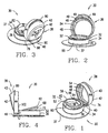
- FIGS. 1-9 There is illustrated in FIGS. 1-9 a preferred embodiment of a re-sealable closure 30 that may be utilized, for example, in conjunction with a gable-top container 31 (see FIG. 7) having a body formed from a paperboard-based substrate that is disposed between outer layers of a thermoplastic polymer material.
- the closure may also be used with a non-paperboard based polyethylene container, or with other types of containers generally.
- the closure 30 is formed as a single, integrally molded piece and generally includes a spout 32 having a stem 34 which is tubular in shape and projects upward from an annular base flange 36 extending about the periphery of the lower end of the stem 34.
- the base flange 36 has a generally circular shape except for a flat portion 37.
- the flat portion 37 is optional and assists in orienting the closure 30 during placement on a container 31.
- the spout 32 is joined with a cap 38 by an integral hinge assembly 40.
- the cap 38 resealably engages the stem 34 of the spout 32.
- the cap 38 includes an upper lid 42 surrounded by a downwardly projecting skirt 44.
- the upper lid 42 may have a beveled edge 43 as a transition between the upper lid 42 and the skirt 44.
- the skirt 44 and lid 42 cooperate to define a vaulted interior cavity which receives an upper portion of the stem 34 when the cap 38 is secured about the stem 34 to close the closure 30.
- An annular recess 46 is formed about the interior of the cap 38 near the intersection of the skirt 44 and the lid 42.
- An interior surface of the skirt 44 includes an inner rib 48 extending about its interior.
- the lid 42 and the rib 48 cooperate to define the recess 46 between them.
- Also included in the interior of the lid 42 are a plurality of engaging rods 49 for engaging with the front of the stem 34. This provides for a tighter reseal of the cap 38 with the spout 32.
- the stem 34 includes an upper end 50 having an outwardly flared lip 52 extending about the exterior periphery of the stem 34.
- the lip 52 engages the recess 46 of the cap 38 when the closure 30 is in a closed position.
- the skirt 44 includes a beveled surface 54 at its mouth to enable the cap 38 to be easily guided over the lip 52.
- the lip 52 and rib 48 engage one another to seal the cap 38 over the stem 34.
- the stem 34 further includes an aperture 56 to enable the contents of the container 31 to be poured out when the cap 38 is removed.
- an optional membrane 58 may be disposed over the aperture 56.
- the membrane 58 is a web integrally formed within the stem 34, in this embodiment. The intersection of the membrane 58 and the interior surface of the stem 34 defining the aperture 56 is weakened by the circular groove 60 defining that intersection.
- the membrane 58 includes an integral pull ring 62, optionally formed at least approximately concentrically with the stem 34.
- the pull ring 62 is secured to the membrane 58 by a post 64 which is integral with the membrane 58.
- the pull ring 62 has a post side 66, a free side 68 approximately diametrically opposed to the post side 66, an inner surface 70, and an outer surface 72.
- One particular feature of the pull ring 62 is its tilted orientation relative to the plane of the lip 52. Specifically, the free side 68 of the pull ring 62 projects out of the stem 34 through the lip 52, exposing the portion of the outer surface 72 on the free side 68 of the pull ring 62.
- the post side 66 of the pull ring 62 is flush with the lip 52, and can optionally be recessed within the stem 34. This orientation of the pull ring has several advantages, such as the following.
- This tilted orientation makes the pull ring 62 easier to grasp than a conventional pull ring which is flush with the lip 52 or recessed within the stem 34. If the pull ring were flush or recessed, access to its outer surface 72 would be prevented by the stem 34, particularly if the dimensions of the closure 30 are small (as they desirably are).
- a flush or recessed ring is usually grasped by inserting a finger or tool to engage the inner surface 70 and lifting the free side 68 of the pull ring 62 out of the stem 34 through the lip 52. Once this is done, the outer surface 72 can be contacted with a second digit, such as the user's thumb, to gain a secure grasp on the pull ring 62.
- the ring can then be pulled as firmly as necessary to tear out and remove the membrane 58.
- the process of extracting the free side 62 of the pull ring 62 from the stem 34 can be awkward for a person who lacks dexterity, has large fingers not easily inserted within the inner surface 70, or prefers to insert one of his or her larger fingers, such as the index finger, into the ring 62.
- the free side 68 of the pull ring 62 can be permanently elevated out of the stem 34, preferably by inclining the entire pull ring 62.
- This expedient allows immediate access to the outer surface 72 without first extracting the free side 68 of the pull ring 62.
- the tilted orientation of the pull ring 62 also allows the cap 38 to have a shorter skirt 44 around part of its circumference, and thus a lower profile for the closure 30, than would otherwise be possible.
- a hinge side 74 of the skirt 44 needs only to be as long as necessary to engage a hinge side 76 of the stem 34, without allowing any additional "head room” above the lip 52 to accommodate the protruding post side 66 of the pull ring 62.
- the only "head room” required by the illustrated embodiment is in the portion of the lid 42 confronting the portion of the free side 68 projecting above the lip 52. Thus, less material can be used for the closure 30 if the pull ring 62 is tilted up from its post side 66 to its free side 68.
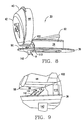
- the particular vaulted design of the cap 38 has both ornamental and functional advantages.
- One of its functional advantages is that, if the closure 30 is oriented with the hinge assembly 40 at a higher elevation than the diametrically opposed edge of the cap 38 on an inclined top panel 82 of a gable top carton 31, as shown in FIG. 7, the surface 80 diametrically opposed to the hinge assembly 40 is roughly parallel to the adjacent side panel 84 of the carton. The surface 80 can thus extend as far above the base flange 36 as necessary to accommodate the raised free side 68 of the pull ring 62, without projecting through the plane of the side panel 84.
- closure 30 of the present invention may be attached to exterior surface of a container 31 and thus is not limited to attached from the interior of the container 31.
- This functional feature could, of course, be provided in a closure having a substantially different shape and appearance of the lid 42, even an entirely flat lid.
- a flat lid atop a skirt of varying height could be accommodated by rotating the pull ring 62 and the post 64 180 degrees, exchanging the free side 68 and the post side 66 of the pull ring 62. This would put the part of the lid 42 which must be highest further from the plane of the side panel 84 than the other part of the lid 42.
- the integral hinge assembly 40 as molded, includes an L-shaped link 88 having a first portion 90 connected to the flange 36 by an integral hinge 92 and a second portion 94 attached to the cap 38 by an integral hinge 96.
- the first portion 90 in this embodiment is about as long as the width of the flange 36, at least in the area of the hinge assembly 40.
- the second portion 94 can be shorter than the height of the stem 34 in the area of the hinge assembly 40.
- the first portion 90 is sized and shaped, and the integral hinge 92 is sufficiently flexible, to allow the first portion 90 to be pivoted into, and in this embodiment just fill, the recess 98 in the base flange 36.
- the second portion 94 elevates the lower margin of the skirt 44 above the base flange 36, thus reducing the necessary height of the skirt 44 and saving material, while reducing the necessary clearance between the inner circumference of the mouth of the skirt 44 and the outer circumference of the lip 52.
- the cap 38 includes a pair of integral props 102 and 104 on the respective sides of the hinge assembly 40.
- the props 102 and 104 are shown most prominently in FIGS. 8 and 9.
- the props 102 and 104 are nearly perpendicular to and bear against the stem 34 to keep the cap 38 clear of the emerging contents of the container 31. This is necessary due to the tendency of the cap 38 to partially reseal during pouring due to the effects of gravity and the cap's 38 shape memory as previously explained.
- the props 102 and 104 preferably maintain the cap 38 at a forty-five degree angle to the top of the stem 34.
- the props 102 and 104 sweep down the stem 34 and are stowed against or near the stem 34 and nearly perpendicular to the base flange 36.
- a step 110 which is integral with the stem 34 of the spout 32.
- the step 110 further assists the prop 102 ( and a corresponding step 110, not shown, assists the prop 104) with preventing interference from the cap 38 during pouring of the contents from a container.
- Both the props 102 and 104 and the steps 110 are integrally formed with the closure 30 as further described below.
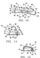
- the closure 30 is formed as a single piece, preferably from a heat sealable thermoplastic material such as polyethylene, by injection molding or the like.
- the closure 30 may be advantageously molded within a single injection molding tool in its expanded position illustrated in FIG. 10.
- Such a molding tool is both simple and economical to form. Additionally, such a tool is easy to maintain.
- the single, integral structure shown here gives rise to a closure 30 that is more economical to manufacture than other closures 30 in common use today, such as those comprising separate cap 38 and spout 32 sections.
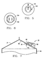
- Another feature of the present invention is an orientation peg 142 which projects from the base flange 36 and is eccentrically positioned relative to the center of the closure 30.
- the peg 142 can be provided by leaving a short column of the material formed in a runner of the mold cavity leading to the underside of the closure 30 when the superfluous material is trimmed from the closure 30.
- the orientation peg 142 can be used to orient the closure 30 when it is to be used in a packaging machine. This step is necessary because the closures 30 are conventionally packed in random orientation in a bulk carton, but each closure 30 should face in the same direction when installed on a package.
- the assembled and oriented closure 30 is inserted into an aperture of a container 31.
- the closure 30 is inserted to the position shown in FIG. 2a so that the flange 36 engages the interior, thermoplastic surface of the container 31.
- the flange 36 may engage the exterior, thermoplastic surface of the container 31.
- the closure 30 is preferably secured to the container 31 by ultrasonic sealing, heat sealing, pressure sealing, or combinations of these types of sealing mechanisms.
- ultrasonic sealing heat sealing, pressure sealing, or combinations of these types of sealing mechanisms.
- An ultrasonic sealing horn may be readily configured to surround the cap 38 and stem 34 and engage the area of the exterior of the container 31 about the flange 36 to permanently secure the flange 36 to the container 31.
- One particular advantage of the present invention is that the sealing force for permanently assembling the hinge assembly 40 to the base flange 36 can be applied by the mechanism which joins the base flange 36 to the container 31.
- the ultrasonic, heat, or other energy applied to the flange 36 to seal the flange 36 to the container 31 also heats the first portion 90 of the L-shaped link 88 and the flange walls defining the recess 98, sealing them together. Once this is done, the recesses 98 is full of plastic and thus no longer interrupt the otherwise smooth, generally annular base flange 36.
- the first portion 90 and the recess 98 are both positioned between the base flange 36 and the inner wall of the container 31 when the assembly is welded together. As a result, most cosmetic imperfections caused by filling the recesses in the base flange are not visible from outside the container 31.
- a standard packaging machine may be used to form the closure 30 and seal it to the container 31 with a minimal amount of additional tooling. This is due, at least in part, to the fact that only one sealing tool, for example an ultrasonic sealing tool, is needed to facilitate the sealing. Thus, the overall cost for tooling is reduced, while part production costs and production maintenance is reduced by utilizing a single-piece, low maintenance injection molding tool in the molding process.
- a further advantage is that the present closure 30 design can be preferably manufactured through a process in which the molding tool is only moved along a single axis running in the mold parting and closing direction.
- FIGS. 15 through 17 illustrate another embodiment 150 of the closure.
- One distinguishing feature of the closure 150 is the shape of its cap 152, which has a generally rounded lid 154 while other variations on this embodiment may have the lid 154 as a flat lid 154..
- the shape of the cap 152 affords a closure 150 having an extremely low height or profile.
- the height of the closure 150 can be the sum of the height of the lip 52 above the flange, plus the thickness of the lid 154, minus the thickness of the container wall through which the closure is inserted.
- This embodiment also has a tamper-evident means 161 which may be connected to the cap and spout by breakable bridges.
- the tamper-evident means has an attachment member 163 for engaging with a recess 165 located on the flange 36.
- the closure 30 shown in FIG. 15 has the tamper-evident means 161 removed after opening of the closure 30.
- Such a similar tamper evident means may be placed on the previous embodiment, on one side or on both sides of the cap.
- the generally cylindrical skirt 156 of the cap 152 is also modified to make the cap 52 easier to close on the stem 34.
- the hinged side 158 of the skirt 156 is shorter than the swinging side 160 of the skirt 156. This change slightly increases the diameter of the mouth 162 of the skirt 156 from the hinge side 158 to the swinging side 160, without decreasing its diameter in the perpendicular direction, and without changing the diameter of the skirt 156 measured parallel to the lid 154.
- the increased long diameter of the oval mouth 162 allows it to more easily capture the portion of the lip 52 which is diametrically opposed to the hinge assembly 40 than a round mouth could do.
- the skirt 156 remains circular in its cross-sections perpendicular to the axis 164, so the skirt 156 mates with the entire circumference of the stem 34 as in the first embodiment.
- closure 150 of FIGS. 15-18 differs from the closure 30 of FIGS. 1-14 in that the closure 150 lacks an integral sealing membrane 58 and pull ring 62.
- a separate membrane tape or patch can be applied to the inside of the container 31 to cover the base flange 36.
- the seating relation of the cap 152 and the spout 32 may be sufficiently fluid-tight, particularly with the tamper-evident structure 161 intact, to allow the membrane 58 to be eliminated.
- a simple folding step can be employed to position the cap, the spout, and the tamper-evident tear strip from their as-molded positions to their closed positions, without requiring "tacking” or other heating operations.
- the closure can be snapped shut reasonably securely, without gluing or welding its parts together, so it will remain closed during handling and can easily be inserted cleanly through a small aperture in a container.
- An orientation peg optionally.formed as a vestige of the plastic remaining in a mold runner, can be provided to cause the closure to self orient with its hinged side trailing when sliding down an incline.
- the orientation ability of the inclined surface may be accentuated by roughening the surface of the incline.
- the closure can have a pull ring for breaking and removing a sealing membrane within the spout.
- the pull ring can be positioned with its free side projecting above the rim of the spout at one point in the spout circumference.
- the pull ring can be contacted on the outside with a finger and pushed further up to permit it to be grabbed. If molded polyethylene (which provides heat-sealability to polyethylene coated board but little resilience), the cap can be vaulted to provide interior room for accommodating the raised part of the pull ring.
- the vaulted cap of the closure can be provided in an aesthetically pleasing configuration which still has a relatively low profile.
- the low profile configuration can also have functional features, such as a front raised surface which extends vertically from a slanted panel of a gable top container so it will not project through the plane of any of the side panels of the container.
- the cap can have one or more molded-in legs extending from the cap near the hinge.
- the legs will erect against the outside of the spout 32 when the cap 38 is opened to hold the cap 38 out of the way of the spout 32.
- These legs can fold against the spout 32 when the cap 38 is closed. This allows the closure 30 to be molded of easily sealed polyethylene, which has no memory and inelastically deforms during storage.
- the tear strip of the tamper-evident structure can be bifurcated by providing a separate pull tab on each of its ends so the closure can be opened equally well by left or right-handed people.
- the tear strip can be molded half-round and out of position so its tabs fit snugly against the cap when folded into position. This feature prevents the tear strip from catching in the aperture through the wall of the container during assembly.
- top edges of the tabs extend above the top of the skirt of the cap. Each of the top edges is easy to push away from the cap so one of the tabs can be securely grasped to tear away the tear strip and open the closure.
- the feet of the tear strip contact the base flange of the closure when the tear strip is folded into place and the closure is closed. This contact rotates the tear strip, tending to urge the second portion of the tamper-evident structure into a recess in the base flange.
- the closures can be easily assembled to their closed positions, and their parts and appendages can stay in their closed positions during further handling without requiring any welding operations or the like.
- the sealing operations necessary to provide a closure durable enough for use can be carried out at the same time the closure is joined to a container wall, using the same ultrasonic tool or other energy source, fastener, or adhesive used to attach the closure to an inside wall of the container. This expedient saves a manufacturing step and avoids deformation of the closure which could be caused by a plastic welding operation carried out on the closure before installing the closure in a container.
- the flat cap alternatively provided in the closure can have an exceedingly low profile.
- the swinging side of the skirt of the closure can be deeper than the hinged side of the skirt. This configuration allows the mouth of the cap to reach slightly further to capture the fee side of the lip of the stem.
- a mold is provided for a closure.
- the mold may be on a injection molding machine which may also have additional molds with a preferred number being 64 molds.
- the mold is filled with a polymeric material to be formed into an integral one-piece closure.
- a preferred polymeric material is polyethylene, however, other polymeric materials may be used in fabricating the closure.
- the mold is opened and a means of conveyance is provided to conveyor the closure from the molding machine to a folding machine.
- the conveyance means may be flat arm having partitioned areas for receiving a closure.
- the closure is attached to the conveyance means. This may occur through pushing of the closure out from the mold by means of a pin.
- the conveyance means may also have a vacuum for receiving the closure.
- the closure is conveyed to an adjacent folding machine.
- the closure is delivered from the conveyance means to a reorienting means.
- the closure is placed on the reorienting means with the bottom of the spout and the top of the cap facing outward in an unfoldable orientation.
- the orientation is unfoldable in that the hinge assembly would be broken if folded, and the spout would not be covered as desired.
- the reorientation means may be a flat sheet having a groove with or without a vacuum for accepting the closure.
- the reorientation means moves and attaches the closure to a folding device thereby reorienting the closure to a foldable orientation with the bottom of the spout and the top of the cap facing inward.
- the cap is folded onto the spout by the folding device.
- the folding device may operate similar to a door hinge in folding the cap onto the spout.
- the closure is released from the folding device onto a conveyor mechanism disposed below for packaging and distribution.
Claims (7)
- Einstückiger Verschluss (30) mit einer Tülle (32), einer Kappe (38) und einer die Kappe (38) mit der Tülle (32) verbindenden Scharniergruppe (40), dank derer die Kappe (38) von der Tülle (32) weg geöffnet und wieder geschlossen werden kann, während die Kappe (38) weiter an der Tülle (32) angebracht bleibt, wobei die Tülle (32) einen Flansch (36) und einen davon abstehenden Schaft (34) hat, der eine Öffnung (56) definiert, wobei die Kappe einen Deckel (42) und eine davon abstehende Schürze (44) hat, dadurch gekennzeichnet, dass die Schürze (44) mindestens eine davon abstehende Strebe (102 oder 104) hat, wobei die Strebe (102 oder 104) am Schaft (34) anliegt, um eine Behinderung durch die Kappe (38) zu verhindern, wenn die Kappe (38) in einem offenen Zustand ist, wobei der Verschluss (30) weiterhin einen Zugring (62) umfasst, der über eine Stütze (64) mit einer Membran (58) verbunden ist, die in der Öffnung (56) angeordnet ist und durch die Betätigung des Zugrings (62) entfernt wird, und wobei die Scharniergruppe (40) eine L-förmige Verbindung (88) umfasst, von der ein erster Abschnitt (90) über ein integrales Scharnier (92) mit dem Flansch (36) und ein zweiter Abschnitt (94) über ein integrales Scharnier (96) mit der Kappe (38) verbunden ist, wobei die Länge des ersten Abschnitts (90) ungefähr der Breite des Flansches (36) im Bereich der Scharniergruppe (40) entspricht und die Länge des zweiten Abschnitts (94) weniger als die Höhe des Schafts (34) im Bereich der Scharniergruppe (40) beträgt.
- Verschluss (30) nach Anspruch 1, weiterhin mit mindestens einem Absatz (110), der am Schaft (34) angebracht ist und im Wesentlichen senkrecht zu dem Flansch (36) ist, wobei die mindestens eine Strebe (102 oder 104) auf dem Absatz (110) ruht, wenn die Kappe im offenen Zustand ist.
- Verschluss (30) nach Anspruch 1 oder 2, bei dem die Kappe (38) zwischen dem Deckel (42) und der Schürze (44) einen abgeschrägten Übergang (43) hat, so dass der Deckel (42) abgewinkelt sein kann, wobei durch den abgewinkelten Deckel (42) dafür gesorgt wird, dass der Zugring (62) entsprechend dem Deckel (42) abgewinkelt ist, wodurch ein Benutzer den Zugring (62) leicht erreichen kann.
- Verschluss (30) nach einem der vorhergehenden Ansprüche, weiterhin mit einem am Verschluss (30) angeordneten Ausrichtungszapfen (142), um den Verschluss (30) angemessen für die Platzierung auf einem Behälter (31) auszurichten, wobei der Ausrichtungszapfen (142) an der vom Schaft (34) aus gesehen gegenüberliegenden Seite des Flansches (36) angeordnet ist.
- Verschluss (30) nach einem der vorhergehenden Ansprüche, weiterhin mit einem Originalitätssicherungsmittel (161), um anzuzeigen, ob der Verschluss (30) geöffnet wurde.
- Verfahren zur Herstellung und für den Umgang mit einem Verschluss (30) mit folgenden Schritten:a) Formen eines Verschlusses (30) nach einem der vorhergehenden Ansprüche in einer Form,b) Entfernen des Verschlusses (30) daraus,c) Transport des Verschlusses (30) in einer aufgeklappten Ausrichtung von der Form zu einem Halteglied einer Klappmaschine,d) Überführen des Verschlusses (30) an ein Klappglied,e) Umkehrung der Ausrichtung des Verschlusses (30) in eine geklappte Ausrichtung.
- Behälter (31) mit einem Verschluss (30) nach einem der Ansprüche 1 - 5 zum Zugriff auf den Inhalt des Behälters (31), wobei der Verschluss (30) um einen Zugriffsbereich des Behälters (31) platziert wird und wobei der Verschluss (30) so an den Behälter (31) geschweißt ist, dass mindestens ein Abschnitt (90) der Scharniergruppe (40) an die Tülle (32) geschweißt ist.
Applications Claiming Priority (3)
| Application Number | Priority Date | Filing Date | Title |
|---|---|---|---|
| US3031296P | 1996-11-01 | 1996-11-01 | |
| US30312P | 1996-11-01 | ||
| PCT/US1997/019421 WO1998019918A2 (en) | 1996-11-01 | 1997-10-28 | One-piece molded flip cap closure |
Publications (2)
| Publication Number | Publication Date |
|---|---|
| EP1019298A2 EP1019298A2 (de) | 2000-07-19 |
| EP1019298B1 true EP1019298B1 (de) | 2004-09-15 |
Family
ID=21853617
Family Applications (2)
| Application Number | Title | Priority Date | Filing Date |
|---|---|---|---|
| EP97947286A Expired - Lifetime EP1019298B1 (de) | 1996-11-01 | 1997-10-28 | Einteilig geformter klappdeckelverschluss, herstellungsverfahren und behälter |
| EP97946320A Expired - Lifetime EP1025009B1 (de) | 1996-11-01 | 1997-10-28 | Einteilig geformter klappdeckelverschluss |
Family Applications After (1)
| Application Number | Title | Priority Date | Filing Date |
|---|---|---|---|
| EP97946320A Expired - Lifetime EP1025009B1 (de) | 1996-11-01 | 1997-10-28 | Einteilig geformter klappdeckelverschluss |
Country Status (16)
| Country | Link |
|---|---|
| US (5) | US6003712A (de) |
| EP (2) | EP1019298B1 (de) |
| JP (2) | JP4002616B2 (de) |
| KR (2) | KR100591233B1 (de) |
| CN (1) | CN1093822C (de) |
| AT (2) | ATE314267T1 (de) |
| AU (2) | AU728236B2 (de) |
| BR (2) | BR9712721A (de) |
| CA (2) | CA2237185C (de) |
| DE (2) | DE69735013T2 (de) |
| ES (1) | ES2252798T3 (de) |
| MX (1) | MX9805346A (de) |
| NO (2) | NO319275B1 (de) |
| NZ (2) | NZ335896A (de) |
| RU (2) | RU2183183C2 (de) |
| WO (2) | WO1998019918A2 (de) |
Cited By (1)
| Publication number | Priority date | Publication date | Assignee | Title |
|---|---|---|---|---|
| CN106144192A (zh) * | 2016-08-31 | 2016-11-23 | 曹蓉蓉 | 一种带汤勺的圆柱形塑料瓶盖及制造该瓶盖的塑料 |
Families Citing this family (123)
| Publication number | Priority date | Publication date | Assignee | Title |
|---|---|---|---|---|
| US6253937B1 (en) * | 1995-06-06 | 2001-07-03 | Raymond G. Anderson | Snap top, easy pouring dispensing cap |
| WO1998019918A2 (en) * | 1996-11-01 | 1998-05-14 | Tetra Laval Holdings & Finance, S.A. | One-piece molded flip cap closure |
| US5852913A (en) * | 1997-03-05 | 1998-12-29 | Tetra Laval Holdings & Finance, Sa | Orientationally sensitive closure and orienting apparatus therefor |
| US6152320A (en) * | 1998-06-08 | 2000-11-28 | Crown Cork & Seal Technologies Corporation | Closure with articulated lid |
| DE19832799B4 (de) * | 1998-07-21 | 2006-03-02 | Kunststoffwerk Kutterer Gmbh & Co. Kg | Aufklappbare Verschlußkappe |
| US6257449B1 (en) * | 1998-09-11 | 2001-07-10 | J. L. Clark | Reclosable package fitment having rear intrusion and front spout lift |
| FR2785264B1 (fr) * | 1998-10-29 | 2001-01-05 | Crown Cork & Seal Tech Corp | Dispositif de bouchage |
| US6109487A (en) * | 1999-02-12 | 2000-08-29 | Dart Industries Inc. | Container with dispensing assembly |
| USD426772S (en) * | 1999-02-22 | 2000-06-20 | Poly-Seal Corporation | Dispensing jar cover |
| US6179147B1 (en) * | 1999-06-03 | 2001-01-30 | Tetra Laval Holdings & Finance, Sa | Closure with flush-formed barrier membrane having selectively thinned edge regions |
| JP4275287B2 (ja) * | 2000-03-30 | 2009-06-10 | 株式会社細川洋行 | プラスチック容器 |
| US6545594B1 (en) * | 2000-05-25 | 2003-04-08 | The Coca-Cola Company | Audio closure |
| EP1160172B1 (de) * | 2000-05-30 | 2004-09-29 | Tetra Laval Holdings & Finance S.A. | Öffnungsvorrichtung für eine Verpackung für fliessfähige Lebensmittel sowie mit derselben versehene Verpackung |
| DE60013577T2 (de) | 2000-06-15 | 2005-02-03 | CROWN Packaging Technology, Inc., Alsip | Dose mit Giesstülle |
| US6269986B1 (en) * | 2000-06-20 | 2001-08-07 | Seaquist Closures Foreign, Inc. | Dispensing closure with tamper evident lid panel |
| US6631820B2 (en) | 2000-12-22 | 2003-10-14 | Seaquist Closures Foreign, Inc. | Tamper-evident dispensing closure with partial breakaway cover |
| US6405885B1 (en) | 2000-12-22 | 2002-06-18 | Seaquist Closures Foreign, Inc. | Locking tamper-evident dispensing closure |
| US7281638B2 (en) * | 2001-07-24 | 2007-10-16 | Obrist Closures Switzerland Gmbh | Snap-hinge closure with tamper-evident lid and method of making |
| US6644487B2 (en) * | 2001-08-17 | 2003-11-11 | Seaquist Closures Foreign, Inc. | Tamper-evident closure with break-off piece retention |
| US7051894B2 (en) * | 2001-10-01 | 2006-05-30 | Wm. Wrigley Jr. Company | Circular dispensing container with a hinged lid |
| NO20020277D0 (no) * | 2002-01-18 | 2002-01-18 | Svein Myhre | Fremgangsmåte ved tilveiebringelse av et hengslet garantilukke, hengslet garantilukke og beholder med hengsletgarantilukke |
| US6789393B2 (en) | 2002-02-11 | 2004-09-14 | S.C. Johnson Home Storage, Inc. | Container with pressure relief and lid and method of manufacture therefor |
| US6923017B2 (en) | 2002-02-11 | 2005-08-02 | S.C. Johnson Home Storage, Inc. | Cooling container having a coolant and pressure relief apparatus |
| WO2003086880A1 (en) * | 2002-04-05 | 2003-10-23 | Campina B.V. | Container for a flowing product and method for manufacturing and filling such a container |
| US6866164B2 (en) | 2002-04-26 | 2005-03-15 | Rexam Medical Packaging Inc. | Child resistant dispenser |
| US20040035867A1 (en) * | 2002-06-27 | 2004-02-26 | S.C. Johnson Home Storage, Inc. | Container including detachable cup and built-in warming tray |
| AUPS323702A0 (en) * | 2002-06-27 | 2002-07-18 | Kratzer, Oliver Clemens Robert | A pouring attachment |
| DE60323493D1 (de) * | 2002-07-12 | 2008-10-23 | Bericap | Verschlussvorrichtung mit einem in schliessposition geformten scharnierdeckel |
| US20050116382A1 (en) * | 2002-07-12 | 2005-06-02 | Philippe Nusbaum | Closure device comprising a hinged cap moulded in the closed position |
| US20050173367A1 (en) * | 2002-07-12 | 2005-08-11 | Philippe Nusbaum | Closure device comprising a hinged cap moulded in the closed position |
| US6848603B2 (en) * | 2002-07-17 | 2005-02-01 | Crown Cork & Seal Technologies Corporation | Closure having improved tamper evident features |
| US7168149B2 (en) * | 2002-09-13 | 2007-01-30 | Husky Injection Molding Systems Ltd. | Apparatus for closing a hinged molded part |
| DE10244349A1 (de) * | 2002-09-24 | 2004-04-15 | Sooth, Jürgen | Verschluss für ausgießbare Flüssigkeiten enthaltene Dosen |
| US6988642B2 (en) * | 2002-10-29 | 2006-01-24 | Johnson & Johnson Consumer Companies | Tamper-evident dispenser bottle |
| US20040082058A1 (en) * | 2002-10-29 | 2004-04-29 | Arthur Schleifer | Array hybridization apparatus and method for making uniform sample volumes |
| GB2428669B (en) * | 2003-03-26 | 2007-08-15 | Portola Packaging Ltd | Closures and containers in combination therewith |
| US20040214310A1 (en) * | 2003-04-25 | 2004-10-28 | Parker Russell A. | Apparatus and method for array alignment |
| US20040244145A1 (en) * | 2003-06-04 | 2004-12-09 | Joseph Anscher | Hinge |
| US6868980B2 (en) * | 2003-06-16 | 2005-03-22 | S. C. Johnson Home Storage, Inc. | Container with detachable, selectively vented lid |
| US20050082305A1 (en) * | 2003-10-15 | 2005-04-21 | Dais Brian C. | Container with selectively vented lid |
| US20050196761A1 (en) * | 2004-03-08 | 2005-09-08 | Thompson Allen C. | Array hybridization apparatus and method |
| US20050202445A1 (en) * | 2004-03-09 | 2005-09-15 | Thompson Allen C. | Thermoplastic array hybridization apparatus and method |
| US20050233036A1 (en) * | 2004-04-14 | 2005-10-20 | Kraft Foods Holdings, Inc. | Rigid reclosable bacon package |
| JP4488307B2 (ja) * | 2004-11-30 | 2010-06-23 | 株式会社吉野工業所 | 合成樹脂製キャップ |
| US20060186078A1 (en) * | 2005-02-22 | 2006-08-24 | David Ziegenhorn | Screw on dispensing closure with structure for preventing removal |
| US7730832B2 (en) * | 2005-04-28 | 2010-06-08 | Eastman Chemical Company | Method and apparatus for forming a bale having substantially flat upper and lower surfaces |
| US7648764B2 (en) * | 2005-06-30 | 2010-01-19 | Uchicago Argonne, Llc | Two-piece container seal and method of manufacture |
| NZ541605A (en) * | 2005-08-01 | 2007-10-26 | Alto Packaging Ltd | Screw closure |
| GB0521930D0 (en) * | 2005-10-27 | 2005-12-07 | Carbonite Corp | Dispensing caps for liquid containers |
| PT1803653E (pt) * | 2005-12-27 | 2012-04-13 | Tetra Laval Holdings & Finance | Bocal para dispositivos de abertura de embalagens seladas de produtos alimentares que se podem vazar |
| EP1986921A1 (de) * | 2006-02-21 | 2008-11-05 | Seaquist Closures, L.L.C. | Behälterverschluss |
| US7806292B2 (en) * | 2006-02-28 | 2010-10-05 | Joseph S Kanfer | Towelette dispenser |
| US20070272647A1 (en) * | 2006-03-31 | 2007-11-29 | Long Charles J | Closure with vertical tear bands |
| US8113374B2 (en) * | 2006-08-21 | 2012-02-14 | Tropicana Products, Inc. | Closure for container having removable portion and sealing membrane |
| PT2091859E (pt) * | 2006-11-20 | 2012-09-04 | Mccormick & Co Inc | Obturador de bocal que não goteja |
| ES1064802Y (es) * | 2007-01-30 | 2007-08-01 | Betapack Sa | Tapon para botellas contenedoras de aceite comestible y otros liquidos alimentarios |
| US7861873B1 (en) | 2007-05-29 | 2011-01-04 | Rexam Closures And Containers Inc. | Flip-top dispensing system with a child resistant latch mechanism |
| US8292101B1 (en) | 2007-05-29 | 2012-10-23 | Remax Healthcare Packaging Inc. | Flip-top dispensing system with a child resistant latch mechanism |
| WO2009026486A1 (en) * | 2007-08-22 | 2009-02-26 | Sanford Redmond | Sealed container outlet with detachable member |
| WO2009070669A1 (en) * | 2007-11-28 | 2009-06-04 | Capitol Spout, Inc. | Cylindrical spout for disposable cartons |
| KR200447717Y1 (ko) * | 2007-12-31 | 2010-02-12 | 티피엘 주식회사 | 봉인 구조를 갖는 껌 포장용기 |
| US20090277861A1 (en) * | 2008-05-08 | 2009-11-12 | Long Jr Charles J | Closure with tamper evident strip |
| CN100532052C (zh) * | 2008-05-14 | 2009-08-26 | 张家港市天江精密模具制造有限公司 | 带刀头的型芯 |
| US8276777B2 (en) | 2008-10-03 | 2012-10-02 | Chuck Shieh | Closure with tamper evident strip for container |
| US8746476B1 (en) | 2009-02-13 | 2014-06-10 | Berlin Packaging, Llc | Closure having a seal piercing unit |
| WO2010118319A1 (en) * | 2009-04-09 | 2010-10-14 | Closure Systems International, Inc. | Tamper-evident dispensing spout |
| EP2248449A1 (de) * | 2009-05-08 | 2010-11-10 | Koninklijke Philips Electronics N.V. | Küchengerät |
| USD613599S1 (en) | 2009-09-11 | 2010-04-13 | Telebrands Corp. | Beverage container closure with pressure release |
| US20110062159A1 (en) * | 2009-09-11 | 2011-03-17 | Ajit Khubani | Beverage container closure with pressure release |
| JP5486753B2 (ja) * | 2009-11-30 | 2014-05-07 | 日本テトラパック株式会社 | 包装容器の製造法、注出口栓及び包装容器 |
| US9093700B2 (en) | 2010-02-26 | 2015-07-28 | Johnson Controls Technology Company | Battery terminal cover |
| US8616406B1 (en) * | 2010-10-29 | 2013-12-31 | Tricorbraun, Inc. | Flip-top preform for blow molding |
| TWI396651B (zh) * | 2010-12-24 | 2013-05-21 | Wei Chuan Foods Corp | Open the opening position of the open bottle cap |
| ES2484366T3 (es) | 2011-03-03 | 2014-08-11 | Aptargroup, Inc. | Cierre con característica de inviolabilidad |
| US8918981B2 (en) | 2011-04-07 | 2014-12-30 | Norwalt Design, Inc. | System and fixture for closing a foldable cap |
| EP2532602A1 (de) * | 2011-06-07 | 2012-12-12 | Nestec S.A. | Einteiliger Verschluss zur Ausstattung eines Behälters |
| MX2011010313A (es) | 2011-09-30 | 2013-04-01 | Jose Rodrigo Oliva Salinas | Tapa de una sola pieza para envases de carton. |
| US8672165B2 (en) * | 2011-11-22 | 2014-03-18 | Spherical Precision, Inc. | Containers with dispensing cap and methods of manufacturing the same |
| GB201205243D0 (en) | 2012-03-26 | 2012-05-09 | Kraft Foods R & D Inc | Packaging and method of opening |
| CN102615787B (zh) * | 2012-04-13 | 2014-06-11 | 台州市黄岩西诺模具有限公司 | 注塑模具的滚轮下压式自动翻盖装置 |
| US10131477B2 (en) * | 2012-05-25 | 2018-11-20 | Stephen Robert | Container top with removable seal |
| US9827729B2 (en) | 2012-05-25 | 2017-11-28 | Phoenix Packaging Operations, LLC | Food container top with integrally formed utensil |
| CN102941964B (zh) * | 2012-11-22 | 2016-05-18 | 中山环亚塑料包装有限公司 | 一种柔性密封型包装盖 |
| GB2511560B (en) | 2013-03-07 | 2018-11-14 | Mondelez Uk R&D Ltd | Improved Packaging and Method of Forming Packaging |
| GB2511559B (en) | 2013-03-07 | 2018-11-14 | Mondelez Uk R&D Ltd | Improved Packaging and Method of Forming Packaging |
| US9334097B2 (en) | 2013-03-15 | 2016-05-10 | Westrock Slatersville, Llc | Dispensing closure |
| US10688294B2 (en) | 2013-06-14 | 2020-06-23 | Bayer Healthcare Llc | Portable fluid delivery system |
| USD747201S1 (en) | 2013-09-18 | 2016-01-12 | Bericap | Closure |
| CN103569460A (zh) * | 2013-10-24 | 2014-02-12 | 青岛海信电器股份有限公司 | 一种塑料扣手以及包装箱 |
| US10589973B2 (en) * | 2013-10-25 | 2020-03-17 | Ats Automation Tooling Systems Inc. | Flexible feeding and closing machine for hinged caps |
| FR3015442B1 (fr) | 2013-12-24 | 2016-02-05 | Bericap | Dispositif de bouchage articule avec indicateur de premiere ouverture |
| CN104742295A (zh) * | 2013-12-27 | 2015-07-01 | 汉达精密电子(昆山)有限公司 | 塑胶产品及其成型方法 |
| MY177223A (en) | 2014-01-10 | 2020-09-09 | Bayer Healthcare Llc | Single use disposable set connector |
| ES2525192A1 (es) * | 2014-04-29 | 2014-12-18 | Industrias Plasticas Triana S.A. | Tapón con precinto |
| ES2805321T3 (es) * | 2014-05-16 | 2021-02-11 | Tetra Laval Holdings & Finance | Lámina de material de envasado para producir un recipiente y método para producir recipientes |
| USD833278S1 (en) | 2014-09-03 | 2018-11-13 | Bericap | Closure for a container |
| JP6536930B2 (ja) * | 2014-09-26 | 2019-07-03 | 大日本印刷株式会社 | 注射剤収納用容器、注射剤入り容器、注射剤入り容器の使用方法、および、注射剤収納用容器に注射剤を収納する方法 |
| CN107427411B (zh) | 2015-01-09 | 2021-04-02 | 拜耳医药保健有限公司 | 具有多次使用可丢弃套件的多流体递送系统及其特征 |
| US9759594B2 (en) | 2015-02-25 | 2017-09-12 | Sonoco Development, Inc. | Container and overcap with hinged spout for metered dispensing |
| CN109328080B (zh) | 2016-06-15 | 2021-08-24 | 拜耳医药保健有限公司 | 多次使用可丢弃系统及其针筒 |
| CN108996007B (zh) * | 2016-06-24 | 2021-05-28 | 佛山市海盈食品有限公司 | 应用于液体包装的瓶盖 |
| EP3519316B1 (de) * | 2016-09-28 | 2023-11-22 | The Procter & Gamble Company | Verschlussmechanismus zur verhinderung des unbeabsichtigten öffnens eines behälters |
| US10759576B2 (en) | 2016-09-28 | 2020-09-01 | The Procter And Gamble Company | Closure interlocking mechanism that prevents accidental initial opening of a container |
| MX2019007417A (es) * | 2016-12-29 | 2019-12-16 | Tetra Laval Holdings & Finance | Envase para productos alimenticios vertibles y metodo para moldear una porcion de abertura polimerica. |
| CN107128589A (zh) * | 2017-06-24 | 2017-09-05 | 东莞市鲸鱼嘴环保科技有限公司 | 拉环出液口瓶盖 |
| JP6856473B2 (ja) * | 2017-07-31 | 2021-04-07 | 株式会社吉野工業所 | ヒンジキャップ |
| EP3489164B1 (de) | 2017-11-23 | 2023-01-25 | The Procter & Gamble Company | Verschluss für einen behälter mit drei positionen |
| EP3489165B1 (de) | 2017-11-23 | 2022-08-17 | The Procter & Gamble Company | Verschluss für einen behälter mit einem asymmetrischen vorsprung |
| DE202018101679U1 (de) | 2018-02-06 | 2018-04-10 | Bergi-Plast Gmbh | Verschluss aus Kunststoff mit Sicherungselement zum Nachweis der Originalität |
| EP3715276B1 (de) * | 2019-03-26 | 2021-09-15 | Tetra Laval Holdings & Finance S.A. | Öffnungsvorrichtung für eine verpackung für rieselfähige produkte |
| IT201900007746A1 (it) * | 2019-05-31 | 2020-12-01 | Sacmi | Tappo con cerniera per un contenitore. |
| RU193451U1 (ru) * | 2019-06-13 | 2019-10-29 | Общество с ограниченной ответственностью "Акваника" | Колпачок для закупоривания бутылки |
| BR112022005550A2 (pt) * | 2019-09-25 | 2022-06-21 | Easy Plast S R L | Dispositivo de abertura/fechamento para um recipiente para produtos derramáveis e método de fechamento/abertura de um recipiente para produtos derramáveis |
| US10843849B1 (en) * | 2019-10-01 | 2020-11-24 | Silgan White Cap LLC | Flip top dispensing closure |
| EP3892558A1 (de) * | 2020-04-09 | 2021-10-13 | Tetra Laval Holdings & Finance S.A. | Deckelanordnung für einen behälter, behälter mit einer deckelanordnung und verfahren zum kuppeln einer deckelanordnung mit einem ausguss |
| JP2023535228A (ja) * | 2020-04-27 | 2023-08-16 | スヴァリン キャップ システムズ アーゲー | 容器のための閉鎖システム、このような閉鎖システムを備えた容器、このような閉鎖システムを容器に取り付けるためのツール、およびこのような閉鎖システムを容器に取り付けるためのプロセス |
| MX2022012483A (es) * | 2020-05-27 | 2022-10-27 | Tetra Laval Holdings & Finance | Montaje de tapa-pico para un envase y envase que tiene un montaje de tapa-pico. |
| EP3915892A1 (de) * | 2020-05-27 | 2021-12-01 | Tetra Laval Holdings & Finance S.A. | Deckel-ausguss-anordnung für eine verpackung, verfahren zur herstellung einer deckel-ausguss-anordnung und verpackung mit einer deckel-ausguss-anordnung |
| USD946981S1 (en) * | 2020-06-18 | 2022-03-29 | Swps University Of Social Sciences And Humanities | Mold |
| US20230055070A1 (en) * | 2021-08-19 | 2023-02-23 | Closure Systems International Inc. | One-piece closure |
| WO2023192377A1 (en) * | 2022-04-01 | 2023-10-05 | Csp Technologies, Inc. | Screw-top cap for container, and method of using and making same |
| EP4282772A1 (de) * | 2022-05-27 | 2023-11-29 | R.T. Holding S.r.l. | Verfahren zur herstellung einer verschlussanordnung und so hergestellte verschlussanordnung |
| US11970727B1 (en) * | 2022-12-30 | 2024-04-30 | Yanhua XIE | Pathogenic microorganism sample collection and preservation device with protection function |
Family Cites Families (68)
| Publication number | Priority date | Publication date | Assignee | Title |
|---|---|---|---|---|
| US1481217A (en) * | 1921-11-21 | 1924-01-15 | Richard E Maloy | Grommet |
| US2901800A (en) * | 1953-09-10 | 1959-09-01 | C E M Company | Self coring grommet |
| US2808972A (en) * | 1955-04-27 | 1957-10-08 | Continental Can Co | Plastic nozzle mounting and method of forming same |
| US2986309A (en) * | 1959-01-19 | 1961-05-30 | Donald W Larson | Dual dispenser and shaker insert |
| US3102332A (en) * | 1960-04-29 | 1963-09-03 | Polymold Plastics Inc | Apparatus for closing a nozzle or spout with a captive cap |
| US3199309A (en) * | 1962-10-29 | 1965-08-10 | Gen Motors Corp | Ice maker of the endless flexible belt type |
| JPS439867Y1 (de) * | 1965-02-19 | 1968-04-30 | ||
| US3412919A (en) * | 1967-01-25 | 1968-11-26 | Inland Container Corp | Apertures for corrugated fiberboard containers |
| US3608771A (en) * | 1969-03-12 | 1971-09-28 | Ex Cell O Corp | Disposable pressure container |
| US3712519A (en) * | 1970-06-25 | 1973-01-23 | Phillips Petroleum Co | Container and closure |
| ES161102Y (es) * | 1970-08-03 | 1971-07-01 | G. Sensat, Hijos, S. A. | Vertedor perfeccionado. |
| DE2159035A1 (de) * | 1971-11-29 | 1973-06-07 | Metal Box Co Ltd | Ausgussvorrichtung fuer fliessfaehige medien |
| US3998354A (en) * | 1975-03-31 | 1976-12-21 | Song John S | Reusable sealed plastic cover |
| US4022357A (en) * | 1975-09-18 | 1977-05-10 | American Flange & Manufacturing Co., Inc. | Retractable pouring spout closure |
| US4124134A (en) * | 1977-08-10 | 1978-11-07 | Sunbeam Plastics Corporation | Child-resistant package for liquids |
| US4483464A (en) * | 1980-10-16 | 1984-11-20 | Toppan Printing Co., Ltd. | Container with a pouring spout |
| US4568005A (en) * | 1983-12-29 | 1986-02-04 | General Foods Corporation | Snap-on closure for bottles |
| US4669640A (en) * | 1984-06-26 | 1987-06-02 | Dai Nippon Insatsu Kabushiki Kaisha Meiji Milk Products Company Limited | Sealed gable top carton having a mouthpiece of one piece molding |
| US4625898A (en) * | 1984-09-11 | 1986-12-02 | Polytop Corporation | Dispensing closure employing living hinge with cams to momentarily deform hinge and recesses to accept cams |
| JPH0340765Y2 (de) * | 1985-05-27 | 1991-08-27 | ||
| US4730771A (en) * | 1985-05-30 | 1988-03-15 | B. D. Wait Co. Limited | Air duct |
| US4705197A (en) * | 1986-07-29 | 1987-11-10 | International Paper Company | Pour spout for containers |
| JPS63166954A (ja) * | 1986-12-27 | 1988-07-11 | Toshiba Corp | セラミツクス部材成形方法 |
| US4730770A (en) * | 1987-06-22 | 1988-03-15 | Pure-Pak Inc. | Flat top end closure for liquid containers |
| US4782996A (en) * | 1987-10-02 | 1988-11-08 | The Procter & Gamble Company | Dispensing package |
| US4830273A (en) * | 1988-05-02 | 1989-05-16 | International Paper Company | Plastic pour spout bonding |
| US4909434A (en) * | 1988-05-20 | 1990-03-20 | The Procter & Gamble Company | Moisture impervious carton having one-piece pouring spout sealed to innermost and outermost surfaces |
| JP2660552B2 (ja) * | 1988-07-29 | 1997-10-08 | 日本クラウンコルク株式会社 | ヒンジ付キャップ |
| SE500540C2 (sv) * | 1988-11-09 | 1994-07-11 | Roby Teknik Ab | Öppningsanordning vid en förpackningsbehållare |
| US5012959A (en) * | 1988-11-17 | 1991-05-07 | International Paper Company | Pour spout and carton construction |
| US4917253A (en) * | 1989-03-30 | 1990-04-17 | Continental Plastics, Inc. | Container-closure with fold over projections |
| FR2647088B1 (fr) * | 1989-05-17 | 1991-11-22 | Rical Sa | Ensemble verseur et capsule de bouchage avec charniere a ressort |
| US4925034A (en) * | 1989-05-19 | 1990-05-15 | Combibloc, Inc. | Package fitment |
| SE463762B (sv) * | 1989-05-31 | 1991-01-21 | Akerlund & Rausing Licens Ab | Aaterfoerslutningslock med oevervikt klaafingerskydd |
| US4964562A (en) * | 1989-06-27 | 1990-10-23 | International Paper Co. | Gable top container having a pour spout fitment |
| DE4015119A1 (de) * | 1989-07-10 | 1991-01-31 | Pkl Verpackungssysteme Gmbh | Quaderfoermige giebelpackung mit im bereich des flachdachs angebrachtem ausgiesser |
| US5065938A (en) * | 1989-09-11 | 1991-11-19 | Champion International Corporation | Gable top carton with resealable pour spout |
| US5125886A (en) * | 1989-12-15 | 1992-06-30 | The Procter & Gamble Company | One piece pouring spout sealed to innermost and outermost surfaces of moisture impervious carton |
| JPH0390833U (de) * | 1989-12-28 | 1991-09-17 | ||
| US4990200A (en) * | 1989-12-29 | 1991-02-05 | Lever Brothers Company | Fitment application process and apparatus |
| US5108029A (en) * | 1990-02-16 | 1992-04-28 | Capitol Spouts, Inc. | Reclosable attachment for containers |
| US5199635A (en) * | 1990-02-16 | 1993-04-06 | Capital Spouts, Inc. | Container having reclosable pour spout mounted thereon |
| US5322176A (en) * | 1990-03-12 | 1994-06-21 | Sreatechnic Ag | Plastic snap hinge with a flexible element generating the snap action |
| US5076493A (en) * | 1990-06-25 | 1991-12-31 | Champion International Corporation | Tamper evident gable top carton with reclosable spout |
| US5101999A (en) * | 1990-07-10 | 1992-04-07 | Combibloc, Inc. | Package closure and package preparation |
| US5152438A (en) * | 1990-07-12 | 1992-10-06 | International Paper Company | Pour spout construction |
| US5244520A (en) * | 1990-07-12 | 1993-09-14 | International Paper Company | Pour spout construction and method |
| US5156295A (en) * | 1991-01-28 | 1992-10-20 | International Paper Company | Bag lined carton with pour spout |
| KR940001910Y1 (ko) * | 1991-05-10 | 1994-03-26 | 김성남 | 액체용기의 마개 |
| ES2090578T3 (es) * | 1991-12-12 | 1996-10-16 | Tetra Laval Holdings & Finance | Capsula de cierre. |
| US5271536A (en) * | 1992-02-07 | 1993-12-21 | Polytop Corporation | Flexible holder for "living" hinge joining lid to closure body of dispensing closure |
| US5297696A (en) * | 1992-04-27 | 1994-03-29 | International Paper Company | Pour spout with piercing insert |
| US5203470A (en) * | 1992-05-05 | 1993-04-20 | The Procter & Gamble Company | Separable bag-in-box composite container |
| CA2151921A1 (en) * | 1992-12-18 | 1994-07-07 | Hoover Universal, Inc. | Container with integrally molded closure/tamper indicator |
| CA2162247C (en) * | 1993-05-18 | 2001-02-13 | Nady Bilani | Container for fluids |
| FR2715635B1 (fr) * | 1994-02-02 | 1996-04-12 | Rical Sa | Capsule de bouchage en matière plastique moulée pour la fermeture de récipients à goulot. |
| DE4409945A1 (de) * | 1994-03-23 | 1995-09-28 | Pkl Verpackungssysteme Gmbh | Quaderförmige Flachgiebelverbundpackung und Verfahren zu ihrer Herstellung |
| JPH07291272A (ja) * | 1994-04-18 | 1995-11-07 | Toyo Kagaku Kk | 流動体容器の注出具 |
| DE4419116C2 (de) * | 1994-06-01 | 1996-03-28 | Riegler Fritz A Gmbh & Co | Behälterverschluß |
| US5601669A (en) * | 1994-10-04 | 1997-02-11 | Portola Packaging, Inc. | Apparatus and method for attaching fitments to cartons |
| US5636771A (en) * | 1995-06-06 | 1997-06-10 | International Paper Company | Frangible pour spout fitment |
| US5716471A (en) * | 1995-10-30 | 1998-02-10 | Elopak Systems Ag | Method for securing articles to laminates |
| US5636785A (en) * | 1996-04-24 | 1997-06-10 | International Paper | Gable top container |
| US5799840A (en) * | 1996-04-25 | 1998-09-01 | Tetra Laval Holdings & Finance, S A | Closure formed as a single, integral part |
| WO1998019918A2 (en) * | 1996-11-01 | 1998-05-14 | Tetra Laval Holdings & Finance, S.A. | One-piece molded flip cap closure |
| US5735426A (en) * | 1996-12-17 | 1998-04-07 | Alcoa Closure Systems International Inc. | Fitment-closure assembly for gable-topped carton |
| US5852913A (en) * | 1997-03-05 | 1998-12-29 | Tetra Laval Holdings & Finance, Sa | Orientationally sensitive closure and orienting apparatus therefor |
| US5992129A (en) * | 1997-03-05 | 1999-11-30 | Tetra Laval Holdings & Finance, Sa | Orienting apparatus for an orientationally sensitive closure |
-
1997
- 1997-10-28 WO PCT/US1997/019421 patent/WO1998019918A2/en active IP Right Grant
- 1997-10-28 AU AU51515/98A patent/AU728236B2/en not_active Ceased
- 1997-10-28 NZ NZ335896A patent/NZ335896A/xx not_active IP Right Cessation
- 1997-10-28 DE DE69735013T patent/DE69735013T2/de not_active Expired - Lifetime
- 1997-10-28 JP JP52150698A patent/JP4002616B2/ja not_active Expired - Fee Related
- 1997-10-28 DE DE69730752T patent/DE69730752D1/de not_active Expired - Fee Related
- 1997-10-28 AT AT97946320T patent/ATE314267T1/de not_active IP Right Cessation
- 1997-10-28 RU RU98114304/13A patent/RU2183183C2/ru not_active IP Right Cessation
- 1997-10-28 ES ES97946320T patent/ES2252798T3/es not_active Expired - Lifetime
- 1997-10-28 US US08/958,996 patent/US6003712A/en not_active Expired - Lifetime
- 1997-10-28 NZ NZ330699A patent/NZ330699A/xx not_active IP Right Cessation
- 1997-10-28 WO PCT/US1997/019420 patent/WO1998019920A1/en active IP Right Grant
- 1997-10-28 EP EP97947286A patent/EP1019298B1/de not_active Expired - Lifetime
- 1997-10-28 AU AU52402/98A patent/AU729237B2/en not_active Ceased
- 1997-10-28 CA CA002237185A patent/CA2237185C/en not_active Expired - Fee Related
- 1997-10-28 JP JP52150798A patent/JP4318754B2/ja not_active Expired - Fee Related
- 1997-10-28 AT AT97947286T patent/ATE276153T1/de not_active IP Right Cessation
- 1997-10-28 KR KR1019980705086A patent/KR100591233B1/ko not_active IP Right Cessation
- 1997-10-28 CA CA002271055A patent/CA2271055C/en not_active Expired - Fee Related
- 1997-10-28 BR BR9712721-3A patent/BR9712721A/pt not_active IP Right Cessation
- 1997-10-28 US US08/958,995 patent/US5934496A/en not_active Expired - Lifetime
- 1997-10-28 KR KR1019997003905A patent/KR100558236B1/ko not_active IP Right Cessation
- 1997-10-28 RU RU99111262/13A patent/RU2191724C2/ru not_active IP Right Cessation
- 1997-10-28 CN CN97191481A patent/CN1093822C/zh not_active Expired - Fee Related
- 1997-10-28 EP EP97946320A patent/EP1025009B1/de not_active Expired - Lifetime
- 1997-10-28 BR BR9706910-8A patent/BR9706910A/pt not_active IP Right Cessation
-
1998
- 1998-06-30 NO NO19983036A patent/NO319275B1/no not_active IP Right Cessation
- 1998-06-30 MX MX9805346A patent/MX9805346A/es not_active IP Right Cessation
- 1998-11-02 NO NO19985114A patent/NO325026B1/no not_active IP Right Cessation
-
1999
- 1999-05-27 US US09/321,394 patent/US6158197A/en not_active Expired - Lifetime
- 1999-05-27 US US09/320,764 patent/US6185906B1/en not_active Expired - Lifetime
- 1999-12-06 US US09/455,296 patent/US6216905B1/en not_active Expired - Fee Related
Cited By (1)
| Publication number | Priority date | Publication date | Assignee | Title |
|---|---|---|---|---|
| CN106144192A (zh) * | 2016-08-31 | 2016-11-23 | 曹蓉蓉 | 一种带汤勺的圆柱形塑料瓶盖及制造该瓶盖的塑料 |
Also Published As
Similar Documents
| Publication | Publication Date | Title |
|---|---|---|
| EP1019298B1 (de) | Einteilig geformter klappdeckelverschluss, herstellungsverfahren und behälter | |
| AU2002312153B9 (en) | Tamper-evident closure and spout fitment | |
| US7721901B1 (en) | Thin-walled plastics bottle, closure and bottling process | |
| US5799840A (en) | Closure formed as a single, integral part | |
| AU2002312153A1 (en) | Tamper-evident closure and spout fitment | |
| MXPA99004183A (en) | One-piece molded flip cap closure | |
| JP2004533974A (ja) | 袋状容器用の不正開封防止機能付封止体と注ぎ口備品 | |
| EP1812228B1 (de) | Verbesserungen von giesstüllenvorrichtungen oder diese betreffend | |
| NZ524428A (en) | Cap closure |
Legal Events
| Date | Code | Title | Description |
|---|---|---|---|
| PUAI | Public reference made under article 153(3) epc to a published international application that has entered the european phase |
Free format text: ORIGINAL CODE: 0009012 |
|
| 17P | Request for examination filed |
Effective date: 19990601 |
|
| AK | Designated contracting states |
Kind code of ref document: A2 Designated state(s): AT BE CH DE DK ES FI FR GB GR IE IT LI LU NL PT SE |
|
| 17Q | First examination report despatched |
Effective date: 20010620 |
|
| GRAP | Despatch of communication of intention to grant a patent |
Free format text: ORIGINAL CODE: EPIDOSNIGR1 |
|
| RTI1 | Title (correction) |
Free format text: ONE-PIECE MOLDED FLIP CAP CLOSURE, METHOD FOR ITS PRODUCTION AND CONTAINER |
|
| RTI1 | Title (correction) |
Free format text: ONE-PIECE MOLDED FLIP CAP CLOSURE, METHOD FOR ITS PRODUCTION AND CONTAINER |
|
| GRAS | Grant fee paid |
Free format text: ORIGINAL CODE: EPIDOSNIGR3 |
|
| GRAA | (expected) grant |
Free format text: ORIGINAL CODE: 0009210 |
|
| AK | Designated contracting states |
Kind code of ref document: B1 Designated state(s): AT BE CH DE DK ES FI FR GB GR IE IT LI LU NL PT SE |
|
| PG25 | Lapsed in a contracting state [announced via postgrant information from national office to epo] |
Ref country code: NL Free format text: LAPSE BECAUSE OF FAILURE TO SUBMIT A TRANSLATION OF THE DESCRIPTION OR TO PAY THE FEE WITHIN THE PRESCRIBED TIME-LIMIT Effective date: 20040915 Ref country code: LI Free format text: LAPSE BECAUSE OF FAILURE TO SUBMIT A TRANSLATION OF THE DESCRIPTION OR TO PAY THE FEE WITHIN THE PRESCRIBED TIME-LIMIT Effective date: 20040915 Ref country code: FI Free format text: LAPSE BECAUSE OF FAILURE TO SUBMIT A TRANSLATION OF THE DESCRIPTION OR TO PAY THE FEE WITHIN THE PRESCRIBED TIME-LIMIT Effective date: 20040915 Ref country code: CH Free format text: LAPSE BECAUSE OF FAILURE TO SUBMIT A TRANSLATION OF THE DESCRIPTION OR TO PAY THE FEE WITHIN THE PRESCRIBED TIME-LIMIT Effective date: 20040915 Ref country code: BE Free format text: LAPSE BECAUSE OF FAILURE TO SUBMIT A TRANSLATION OF THE DESCRIPTION OR TO PAY THE FEE WITHIN THE PRESCRIBED TIME-LIMIT Effective date: 20040915 Ref country code: AT Free format text: LAPSE BECAUSE OF FAILURE TO SUBMIT A TRANSLATION OF THE DESCRIPTION OR TO PAY THE FEE WITHIN THE PRESCRIBED TIME-LIMIT Effective date: 20040915 |
|
| REG | Reference to a national code |
Ref country code: GB Ref legal event code: FG4D Ref country code: CH Ref legal event code: EP |
|
| REG | Reference to a national code |
Ref country code: IE Ref legal event code: FG4D |
|
| REF | Corresponds to: |
Ref document number: 69730752 Country of ref document: DE Date of ref document: 20041021 Kind code of ref document: P |
|
| PG25 | Lapsed in a contracting state [announced via postgrant information from national office to epo] |
Ref country code: LU Free format text: LAPSE BECAUSE OF NON-PAYMENT OF DUE FEES Effective date: 20041028 Ref country code: IE Free format text: LAPSE BECAUSE OF NON-PAYMENT OF DUE FEES Effective date: 20041028 |
|
| PG25 | Lapsed in a contracting state [announced via postgrant information from national office to epo] |
Ref country code: SE Free format text: LAPSE BECAUSE OF FAILURE TO SUBMIT A TRANSLATION OF THE DESCRIPTION OR TO PAY THE FEE WITHIN THE PRESCRIBED TIME-LIMIT Effective date: 20041215 Ref country code: GR Free format text: LAPSE BECAUSE OF FAILURE TO SUBMIT A TRANSLATION OF THE DESCRIPTION OR TO PAY THE FEE WITHIN THE PRESCRIBED TIME-LIMIT Effective date: 20041215 Ref country code: DK Free format text: LAPSE BECAUSE OF FAILURE TO SUBMIT A TRANSLATION OF THE DESCRIPTION OR TO PAY THE FEE WITHIN THE PRESCRIBED TIME-LIMIT Effective date: 20041215 |
|
| PG25 | Lapsed in a contracting state [announced via postgrant information from national office to epo] |
Ref country code: ES Free format text: LAPSE BECAUSE OF FAILURE TO SUBMIT A TRANSLATION OF THE DESCRIPTION OR TO PAY THE FEE WITHIN THE PRESCRIBED TIME-LIMIT Effective date: 20041226 |
|
| REG | Reference to a national code |
Ref country code: CH Ref legal event code: PL |
|
| NLV1 | Nl: lapsed or annulled due to failure to fulfill the requirements of art. 29p and 29m of the patents act | ||
| PG25 | Lapsed in a contracting state [announced via postgrant information from national office to epo] |
Ref country code: DE Free format text: LAPSE BECAUSE OF NON-PAYMENT OF DUE FEES Effective date: 20050503 |
|
| ET | Fr: translation filed | ||
| PLBE | No opposition filed within time limit |
Free format text: ORIGINAL CODE: 0009261 |
|
| STAA | Information on the status of an ep patent application or granted ep patent |
Free format text: STATUS: NO OPPOSITION FILED WITHIN TIME LIMIT |
|
| REG | Reference to a national code |
Ref country code: IE Ref legal event code: MM4A |
|
| 26N | No opposition filed |
Effective date: 20050616 |
|
| PG25 | Lapsed in a contracting state [announced via postgrant information from national office to epo] |
Ref country code: PT Free format text: LAPSE BECAUSE OF NON-PAYMENT OF DUE FEES Effective date: 20050215 |
|
| PGFP | Annual fee paid to national office [announced via postgrant information from national office to epo] |
Ref country code: IT Payment date: 20101022 Year of fee payment: 14 Ref country code: GB Payment date: 20101027 Year of fee payment: 14 |
|
| PGFP | Annual fee paid to national office [announced via postgrant information from national office to epo] |
Ref country code: FR Payment date: 20111103 Year of fee payment: 15 |
|
| GBPC | Gb: european patent ceased through non-payment of renewal fee |
Effective date: 20121028 |
|
| REG | Reference to a national code |
Ref country code: FR Ref legal event code: ST Effective date: 20130628 |
|
| PG25 | Lapsed in a contracting state [announced via postgrant information from national office to epo] |
Ref country code: GB Free format text: LAPSE BECAUSE OF NON-PAYMENT OF DUE FEES Effective date: 20121028 |
|
| PG25 | Lapsed in a contracting state [announced via postgrant information from national office to epo] |
Ref country code: FR Free format text: LAPSE BECAUSE OF NON-PAYMENT OF DUE FEES Effective date: 20121031 Ref country code: IT Free format text: LAPSE BECAUSE OF NON-PAYMENT OF DUE FEES Effective date: 20121028 |