EP1016830B1 - Brennkammer für eine Gasturbine - Google Patents
Brennkammer für eine Gasturbine Download PDFInfo
- Publication number
- EP1016830B1 EP1016830B1 EP99811182A EP99811182A EP1016830B1 EP 1016830 B1 EP1016830 B1 EP 1016830B1 EP 99811182 A EP99811182 A EP 99811182A EP 99811182 A EP99811182 A EP 99811182A EP 1016830 B1 EP1016830 B1 EP 1016830B1
- Authority
- EP
- European Patent Office
- Prior art keywords
- combustion chamber
- chamber
- torus
- annular
- diffuser
- Prior art date
- Legal status (The legal status is an assumption and is not a legal conclusion. Google has not performed a legal analysis and makes no representation as to the accuracy of the status listed.)
- Expired - Lifetime
Links
Images
Classifications
-
- F—MECHANICAL ENGINEERING; LIGHTING; HEATING; WEAPONS; BLASTING
- F23—COMBUSTION APPARATUS; COMBUSTION PROCESSES
- F23R—GENERATING COMBUSTION PRODUCTS OF HIGH PRESSURE OR HIGH VELOCITY, e.g. GAS-TURBINE COMBUSTION CHAMBERS
- F23R3/00—Continuous combustion chambers using liquid or gaseous fuel
- F23R3/02—Continuous combustion chambers using liquid or gaseous fuel characterised by the air-flow or gas-flow configuration
-
- F—MECHANICAL ENGINEERING; LIGHTING; HEATING; WEAPONS; BLASTING
- F23—COMBUSTION APPARATUS; COMBUSTION PROCESSES
- F23R—GENERATING COMBUSTION PRODUCTS OF HIGH PRESSURE OR HIGH VELOCITY, e.g. GAS-TURBINE COMBUSTION CHAMBERS
- F23R3/00—Continuous combustion chambers using liquid or gaseous fuel
- F23R3/42—Continuous combustion chambers using liquid or gaseous fuel characterised by the arrangement or form of the flame tubes or combustion chambers
Definitions
- the present invention relates to the field of gas turbines. It affects a combustion chamber for a gas turbine, in which combustion chamber with fuel mixed with an air stream entering the combustion chamber and then is burned, and the resulting combustion air flow downstream of the combustion chamber is fed to a turbine.
- a combustion chamber for a gas turbine in which combustion chamber with fuel mixed with an air stream entering the combustion chamber and then is burned, and the resulting combustion air flow downstream of the combustion chamber is fed to a turbine.
- gas turbines are often designed in such a way that the one passed through them Air flow through two combustion chambers and, accordingly, twice over turbines is directed.
- the air drawn in is initially passed through a compressor group led, and then passed into a primary combustion chamber, where supplied Fuel-air mixture is ignited and burned.
- Fuel-air mixture is ignited and burned.
- From the primary combustion chamber the hot combustion air flows over a first turbine and becomes downstream fed to the first turbine of a secondary combustion chamber, where fuel and if necessary additional air is added and the mixture ignites. Since the from the gases escaping from the first turbine are often very hot, i.e. above the auto-ignition temperature of the fuels can be in the secondary combustion chamber mostly do without active ignition. Downstream of the secondary combustion chamber there is then a second turbine, over which the hot combustion gases flow out of the secondary combustion chamber.
- Such gas turbines the individual components usually in series along a major axis of the Gas turbine arranged.
- a gas turbine group is from, for example EP 0 620 362 A1 known.
- the individual channels for the air flows and the combustion chambers are mostly all in the form of hollow cylinders, which reach around the axis of the gas turbine.
- Secondary combustion chambers for such gas turbines are generally proportionate simply designed because they do not need burners, but the fuel after a suitable swirling of the hot ones emerging from the first turbine Air can simply be injected into the air flow via nozzles, and itself the mixture ignites itself after a characteristic time.
- the hollow-cylindrical secondary combustion chamber is, for example, out known from EP 0 669 500 A1.
- the task is thereby in a combustion chamber of the type mentioned solved that the combustion chamber has an annular diffuser, in which the air flow enters that downstream of and in connection with the diffuser standing at least one substantially annular toroidal chamber arranged is that downstream of the annular toroidal chamber and over its circumference distributed mixing tubes branch, and that downstream of the mixing tubes an annular Combustion chamber is arranged, in which the mixing tubes open.
- the core the invention consists in the combination of diffuser, toroidal ring Chamber and mixing tubes have a premixing structure available too place in which air flowing through in an optimal manner, i.e. fast and can be mixed efficiently with fuel. Another advantage comes from that the proposed configuration is reduced to thermoacoustic Oscillations tend.
- a first preferred embodiment of the combustion chamber according to the invention is characterized in that the combustion chamber as a secondary combustion chamber is designed, and that the gas turbine has a primary combustion chamber, a downstream the primary combustion chamber acting first turbine, a downstream of the first turbine acting secondary combustion chamber, and one downstream of the secondary combustion chamber has acting second turbine.
- the use of the combustion chamber as a secondary combustion chamber is advantageous, especially with such use at high Mach numbers short mixing times are required.
- the ignition as described in a further embodiment, in the secondary combustion chamber is done by self-ignition, the quick and backflow-free mixing is in the proposed arrangement advantageous, and so it can controlled combustion in the area of the outlet of the mixing tubes in the combustion chamber or in Combustion chamber can be guaranteed.
- the diffuser is designed such that the parallel air flow flowing to the gas turbine axis and entering the combustion chamber is initially deflected in a substantially radial direction, and that the Diffuser acts in a tangential manner on the toroidal chamber, so that the air flow entering the toroidal chamber curls up in the torus and swirls around the toroidal minor axis of the torus.
- the mixing tubes on the one essentially opposite the diffuser Side attached in a manner essentially parallel to the axis of the gas turbine In this way, two swirls of different screw rotation meet in front of the mixing tubes on top of each other, and then flow with mutual mixing and Annihilation of the vertebrae through the mixing tubes.
- the proposed design of the combustion chamber is based, among other things, on the spectacular merging and mixing behavior of colliding, with opposing Rotating, rotating, subcritical vortices. This phenomenon occurred on Flow behavior in front of and in radial outlet pipes of steam turbines discovered. It is shown there that only when radial outlet pipes are attached the loss of free flow of the rotating air is possible, while losses occur due to swirling in simple openings. A detailed look at the behavior of the air flow before and in one Such a radial outlet tube shows that two in front of the tubes with opposite directions Rotating, rotating subcritical vortices collide, and the rotation of the two vertebrae within a distance of less than one Completely cancel each other out.
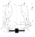
- FIG. 1 shows a longitudinal section along the axis 21 of a gas turbine.
- the entire three-dimensional combustion chamber structure is essentially obtained by rotating the section about axis 21, i.e. it deals the channeling components with the exception of the mixing tubes 22 Axially symmetrical parts about the axis 21 of the gas turbine.
- the hot one from the first Combustion chamber, the primary combustion chamber, escaping airflow flows at the shown gas turbine first via a first turbine 11, which in one Bearing 31 is stored.
- There is a short one downstream of the first turbine 11 hollow cylindrical discharge line 12 through which the air flow from the first Turbine 10 flows parallel to the axis 21 of the gas turbine.
- the outflow pipe 12 is preferably just long enough that the axial hollow cylindrical Flow profile in the airflow 10 can recover.
- Downstream of the discharge line 12 is a diffuser 13 in which the air flow is controlled by the axial direction is deflected. The deflection occurs after in Figure 1 outside in an almost radial direction, but it is also conceivable in principle that Distraction inside.
- the curvature of the diffuser 13 can with the help of the inverse Euler equations can be optimized. It is essentially in the diffuser 13 therefore, the average flow velocity of the air flow approximately cut in half.
- the diffuser 13 abuts a toroidal ring in a tangential manner downstream Chamber 14 to.
- the torus 14 is arranged perpendicular to the axis 21 of the generator, with a large torus radius 29 around axis 21, i.e. the major toric axis 27 and the axis 21 of the generator coincide.
- the circular line of the large torus radius 29 forms the annular torus minor axis 26, and the Torus outer wall 30 is formed by a small torus radius 28 around the ring Secondary torus axis 26 formed.
- a plurality are located downstream of the toroidal annular chamber 14 of mixing tubes 22 which are perpendicular to the toroidal secondary axis 26 of branch off the chamber 14 and are distributed over the circumference of the chamber 14. Through these mixing tubes 22, the air flow rolled up in the torus 14 flows out of the annular toroidal chamber 14 from.
- the mixing tubes 22 are cylindrical or at least partially conical and preferably have a radius in the area of the small torus radius 28.
- the actual combustion chamber 18, which again essentially as a hollow cylinder is formed around the axis 21, and downstream of this combustion chamber 18 is a second turbine arranged.
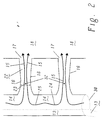
- Figure 2 shows part of a conical section through the chamber 14 and Mixing tubes 22 along the plane X-X in Figure 1 in view from the outside in.
- the behavior of the air flow in the chamber can be determined on the basis of this section 14 and the mixing tubes 22 illustrate.
- Air flow which is tangent to the center between two mixing tubes 22 Diffuser 13 enters the chamber 14, this separates into two to the left and vertebrae 24 and 25 evading to the right, which are different Screw direction, 24 corresponds to a left-handed screw, 25 a clockwise.
- Each of the partial vertebrae 24 and 25 now "screws" in Direction of the nearest mixing tube 22 to flow out of the chamber 14 there to be able to.
- Nozzles 32 are arranged with which liquid or gaseous Fuel can be injected.
- liquid Fuel can also be supplied through nozzles 20, which are located opposite the mixing tubes 22 Wall sides of the toroidal chamber 14 attached are injected into the air flow:
- nozzles 20 which are located opposite the mixing tubes 22
- Wall sides of the toroidal chamber 14 attached are injected into the air flow:
- Auto-ignition characteristic of the injected fuel according to the temperature of the Airflow and flow velocity are formed by auto-ignition of the mixture due to the high air temperature a flame front, which either at the area of the outlet of the mixing tubes 22 or behind it in the combustion chamber 18 can come to rest.
- a I u I A e u e .
- a I and A E are the cross-sectional areas of the tangential entry of the diffuser 13 into the annular toroidal chamber 14 and the cross-sectional area 23 of the mixing tubes 22, and u I and u E are the corresponding flow velocities.
- Table 1 gives the values for a secondary combustion chamber with 12 mixing tubes 22, each with an output radius of 300 mm.
- Size unit Value 1 Value 2 Large radius of the torus m 0.0675 0.0675 Small radius of the torus m 0.0275 0.0275 Width of the entry slot m 0.0085 0.0135 Radius of the tangential input m 0.04425 0.04675 Area of the entrance slot per swirl arm, A I m ⁇ 2 0.01182 0.001983 Eccentricity radius , r I m 0.02325 0.02075 Cross-sectional area of the vertebral arm, A E m ⁇ 2 0.002376 0.002376 vertebrae 1.70 0.90
Landscapes
- Engineering & Computer Science (AREA)
- Chemical & Material Sciences (AREA)
- Combustion & Propulsion (AREA)
- Mechanical Engineering (AREA)
- General Engineering & Computer Science (AREA)
- Fluidized-Bed Combustion And Resonant Combustion (AREA)
Description
- Fig. 1
- einen axialen Längsschnitt durch einen Teil einer Gasturbine mit Sekundärbrennkammer;
- Fig. 2
- eine Teilansicht eines Schnittes entlang der Konusebene X-X aus Figur 1 in einer Ansicht von aussen nach innen; und
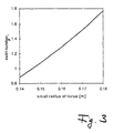
- Fig. 3
- die Wirbelzahl (swirl number) als Funktion des kleinen Torusradius (small radius of torus) in Metern.
| Grösse | Einheit | Wert |
| Massenfluss | kg/s | 450.4 |
| Dichte | kg/m∧3 | 3.81 |
| Anzahl Mischröhren | 12 | |
| Austrittsgeschwindigkeit | m/s | 140 |
| Grosser Torusradius | m | 1.4 |
| Kleiner Torusradius | m | 0.15 |
| Weite des Eintrittsschlitzes | m | 0.12 |
| Volumenfluss | m^3/s | 118.215 |
| Durchmesser der Mischröhren beim Ausgang | m | 0.2993 |
| Gesamte Austrittsfläche | m^2 | 0.8444 |
| Radius des tangentialen Eingangs | m | 1.25 |
| Gesamte Fläche des Eingangsschlitzes | m^2 | 0.9425 |
| Strömungsgeschwindigkeit beim Ausgangsschlitz | m/s | 125.43 |
| Fläche des Eingangsschlitzes pro Wirbelarm, AI | m^2 | 0.03927 |
| Exzentrizitätsradius, rI | m | 0.09 |
| Querschnittsfläche des Wirbel arms, AE | m^2 | 0.07069 |
| Wirbelzahl | 1.08 |
| Grösse | Einheit | Wert 1 | Wert 2 |
| Grosser Torusradius | m | 0.0675 | 0.0675 |
| Kleiner Torusradius | m | 0.0275 | 0.0275 |
| Weite des Eintrittsschlitzes | m | 0.0085 | 0.0135 |
| Radius des tangentialen Eingangs | m | 0.04425 | 0.04675 |
| Fläche des Eingangsschlitzes pro Wirbelarm, AI | m^2 | 0.01182 | 0.001983 |
| Exzentrizitätsradius, rI | m | 0.02325 | 0.02075 |
| Querschnittsfläche des Wirbelarms, AE | m^2 | 0.002376 | 0.002376 |
| Wirbelzahl | 1.70 | 0.90 |
- 10
- Luftstrom aus erster Turbine
- 11
- erste Turbine
- 12
- Ausstömleitung der ersten Turbine
- 13
- Diffusor
- 14
- ringförmig toroidale Kammer
- 15
- Trajektorie des Wirbelzentrums
- 16
- Wandung der Mischröhre
- 17
- Ausgang der Mischröhre
- 18
- Brennraum
- 19
- Ausgang von 18 zur zweiten Turbine
- 20
- Einspritzdüse für flüssigen Brennstoff
- 21
- Achse der Gasturbine
- 22
- Mischröhre
- 23
- Querschnittsfläche der Mischröhre
- 24,25
- gegenläufig rotierende Teilströme des Luftstroms
- 26
- Torusnebenachse
- 27
- Torushauptachse
- 28
- kleiner Torusradius
- 29
- grosser Torusradius
- 30
- Torusaussenwand
- 31
- Lager der ersten Turbine
- 32
- Einspritzdüsen für Brennstoff
- 33
- Verbrennungsluftstrom
Claims (12)
- Brennkammer (13,14,18,22) für eine Gasturbine, in welcher Brennkammer (13,14,18,22) Brennstoff mit einem in die Brennkammer (13,14,18,22) eintretenden Luftstrom (10) vermischt und anschliessend verbrannt wird, und der entstehende Verbrennungsluftstrom (33) stromab der Brennkammer (13,14,18,22) einer Turbine zugeführt wird,
dadurch gekennzeichnet, dass
die Brennkammer (13,14,18,22) einen ringförmigen Diffusor (13) aufweist, in welchen der Luftstrom (10) eintritt, dass stromab des Diffusors (13) und mit diesem in Verbindung stehend mindestens eine im wesentlichen ringförmige toroidale Kammer (14) angeordnet ist, dass stromab der ringförmigen toroidalen Kammer (14) und über deren Umfang verteilt Mischröhren (22) abzweigen, und dass stromab der Mischröhren (22) ein ringförmiger Brennraum (18) angeordnet ist, in welchen die Mischröhren (22) einmünden. - Brennkammer (13,14,18,22) nach Anspruch 1, dadurch gekennzeichnet, dass die Brennkammer als Sekundärbrennkammer (13,14,18,22) ausgebildet ist, und dass die Gasturbine eine Primärbrennkammer, eine stromab der Primärbrennkammer wirkende erste Turbine (11), eine stromab der ersten Turbine (11) wirkende Sekundärbrennkammer (13,14,18,22), sowie eine stromab der Sekundärbrennkammer (13,14,18,22) wirkende zweite Turbine aufweist.
- Brennkammer (13,14,18,22) nach Anspruch 2, dadurch gekennzeichnet, dass die ringförmige toroidale Kammer (14) eine ringförmige Torusnebenachse (26) aufweist, welche mit einem grossen Torusradius (29) um eine Torushauptachse (27) verläuft, und bei welcher ringförmigen toroidalen Kammer (14) eine Torusaussenwand (30) mit einem kleinen Torusradius (28) um die Torusnebenachse (26) gebildet wird, und dass die Torushauptachse (27) im wesentlichen parallel zur Achse (21) der Gasturbine ausgerichtet ist.
- Brennkammer (13,14,18,22) nach Anspruch 3, dadurch gekennzeichnet, dass die Mischröhren (22) im wesentlichen konisch oder zylindrisch ausgebildet sind, und dass die Achsen der Mischröhren (22) ausserhalb der Ebene der ringförmigen toroidalen Kammer (14) und im wesentlichen senkrecht zur ringförmigen Torusnebenachse (26) angeordnet sind.
- Brennkammer (13,14,18,22) nach Anspruch 3, dadurch gekennzeichnet, dass der Radius der Mischröhren (22) im Bereich oder insbesondere bevorzugt gleich wie der kleine Torusradius (28) ausgebildet ist.
- Brennkammer (13,14,18,22) nach einem der Ansprüche 4 oder 5, dadurch gekennzeichnet, dass die Primärbrennkammer eine Ringbrennkammer ist, dass zwischen der ersten Turbine (11) und dem Diffusor (13) eine als Hohlzylinder ausgebildete Ausströmleitung (12) angeordnet ist, und dass die Achse der Ausströmleitung (12) parallel zur Achse (21) der Gasturbine verläuft.
- Brennkammer (13,14,18,22) nach Anspruch 6, dadurch gekennzeichnet, dass der ringförmige Diffusor (13) derart ausgebildet ist, dass der durch die Ausströmleitung (12) parallel zur Achse (21) der Gasturbine strömende Luftstrom (10) vom Diffusor (13) abgelenkt wird, und dass insbesondere bevorzugt diese Ablenkung in im wesentlichen radial zur Achse (21) der Gasturbine verlaufender Richtung bewirkt wird.
- Brennkammer (13,14,18,22) nach einem der Ansprüche 6 oder 7, dadurch gekennzeichnet, dass der Diffusor (13) in tangentialer Weise an die ringförmig toroidale Kammer (14) angreift.
- Brennkammer (13,14,18,22) nach Anspruch 8, dadurch gekennzeichnet, dass Diffusor (13) derart ausgebildet ist, dass der Luftstrom (10) vom Diffusor (13) im wesentlichen radial nach aussen umgeleitet wird, und dass der Diffusor (13) in tangentialer Weise von innen an die ringförmige toroidale Kammer (14) angreift.
- Brennkammer (13,14,18,22) nach einem der Ansprüche 8 oder 9, dadurch gekennzeichnet, dass die Mischröhren (16) im wesentlichen der Eintrittsöffnung des Diffusors (13) in die ringförmige toroidale Kammer (14) gegenüber angeordnet sind, und dass sie im wesentlichen parallel zur Achse (21) der Gasturbine ausgerichtet sind.
- Brennkammer (13,14,18,22) nach Anspruch 10, dadurch gekennzeichnet, dass entweder auf der den Mischröhren (16) abgewandten Rückseite der ringförmigen toroidalen Kammer (14) oder im zentralen Bereich der Mischröhren (16) stromab der ringförmigen toroidalen Kammer (14) Mittel (20,32).angeordnet sind, mit welchen flüssiger Brennstoff eingedüst werden kann.
- Brennkammer (13,14,18,22) nach einem der Ansprüche 10 oder 11, dadurch gekennzeichnet, dass im zentralen Bereich der Mischröhren (16) stromab der ringförmigen toroidalen Kammer (14) Mittel (32) angeordnet sind, über welche gasförmiger Brennstoff eingedüst werden kann.
Applications Claiming Priority (2)
| Application Number | Priority Date | Filing Date | Title |
|---|---|---|---|
| DE19860583 | 1998-12-29 | ||
| DE19860583A DE19860583A1 (de) | 1998-12-29 | 1998-12-29 | Brennkammer für eine Gasturbine |
Publications (3)
| Publication Number | Publication Date |
|---|---|
| EP1016830A2 EP1016830A2 (de) | 2000-07-05 |
| EP1016830A3 EP1016830A3 (de) | 2002-07-24 |
| EP1016830B1 true EP1016830B1 (de) | 2004-05-26 |
Family
ID=7893029
Family Applications (1)
| Application Number | Title | Priority Date | Filing Date |
|---|---|---|---|
| EP99811182A Expired - Lifetime EP1016830B1 (de) | 1998-12-29 | 1999-12-21 | Brennkammer für eine Gasturbine |
Country Status (3)
| Country | Link |
|---|---|
| US (1) | US6272864B1 (de) |
| EP (1) | EP1016830B1 (de) |
| DE (2) | DE19860583A1 (de) |
Families Citing this family (2)
| Publication number | Priority date | Publication date | Assignee | Title |
|---|---|---|---|---|
| US11175046B2 (en) | 2019-05-09 | 2021-11-16 | General Electric Company | Combustor premixer assembly including inlet lips |
| CN116892736B (zh) * | 2023-07-10 | 2025-10-17 | 中国人民解放军空军工程大学 | 一种旋转爆震燃烧室分布式喷油装置及方法 |
Family Cites Families (16)
| Publication number | Priority date | Publication date | Assignee | Title |
|---|---|---|---|---|
| DE1011670B (de) * | 1955-06-03 | 1957-07-04 | H C Ernst Schmidt Dr Ing Dr Re | Ringfoermige Misch- oder Brennkammer, insbesondere fuer Gasturbinen |
| US3309866A (en) * | 1965-03-11 | 1967-03-21 | Gen Electric | Combustion process and apparatus |
| DE2232025A1 (de) * | 1972-06-30 | 1974-01-17 | Motoren Turbinen Union | Gasturbinenanlage, insbesondere triebwerk mit gleichraumverbrennung |
| US4081957A (en) * | 1976-05-03 | 1978-04-04 | United Technologies Corporation | Premixed combustor |
| US4073137A (en) * | 1976-06-02 | 1978-02-14 | United Technologies Corporation | Convectively cooled flameholder for premixed burner |
| GB2098719B (en) * | 1981-05-20 | 1984-11-21 | Rolls Royce | Gas turbine engine combustion apparatus |
| DE3661224D1 (en) * | 1985-02-26 | 1988-12-22 | Bbc Brown Boveri & Cie | Gas turbine combustor |
| JPS62158927A (ja) | 1986-01-07 | 1987-07-14 | Nissan Motor Co Ltd | 環型燃焼器 |
| US4838029A (en) * | 1986-09-10 | 1989-06-13 | The United States Of America As Represented By The Secretary Of The Air Force | Externally vaporizing system for turbine combustor |
| CH679799A5 (de) * | 1988-07-25 | 1992-04-15 | Christian Reiter | |
| DE3942042A1 (de) * | 1989-12-20 | 1991-06-27 | Bmw Rolls Royce Gmbh | Brennkammer fuer eine gasturbine mit luftunterstuetzten brennstoffzerstaeuberduesen |
| DE4236071C2 (de) * | 1992-10-26 | 2002-12-12 | Alstom | Verfahren für eine Mehrstufenverbrennung in Gasturbinen |
| US5575153A (en) * | 1993-04-07 | 1996-11-19 | Hitachi, Ltd. | Stabilizer for gas turbine combustors and gas turbine combustor equipped with the stabilizer |
| CH687269A5 (de) | 1993-04-08 | 1996-10-31 | Abb Management Ag | Gasturbogruppe. |
| CA2141066A1 (en) * | 1994-02-18 | 1995-08-19 | Urs Benz | Process for the cooling of an auto-ignition combustion chamber |
| EP0870990B1 (de) * | 1997-03-20 | 2003-05-07 | ALSTOM (Switzerland) Ltd | Gasturbine mit toroidaler Brennkammer |
-
1998
- 1998-12-29 DE DE19860583A patent/DE19860583A1/de not_active Withdrawn
-
1999
- 1999-12-21 EP EP99811182A patent/EP1016830B1/de not_active Expired - Lifetime
- 1999-12-21 DE DE59909580T patent/DE59909580D1/de not_active Expired - Fee Related
- 1999-12-23 US US09/470,964 patent/US6272864B1/en not_active Expired - Fee Related
Also Published As
| Publication number | Publication date |
|---|---|
| DE59909580D1 (de) | 2004-07-01 |
| US6272864B1 (en) | 2001-08-14 |
| EP1016830A2 (de) | 2000-07-05 |
| DE19860583A1 (de) | 2000-07-06 |
| EP1016830A3 (de) | 2002-07-24 |
Similar Documents
| Publication | Publication Date | Title |
|---|---|---|
| DE60007946T2 (de) | Eine Brennkammer | |
| EP0675322B1 (de) | Vormischbrenner | |
| EP0918191B1 (de) | Brenner für den Betrieb eines Wärmeerzeugers | |
| EP1141628B1 (de) | Brenner zum betrieb eines wärmeerzeugers | |
| EP0718561B1 (de) | Brennkammer | |
| EP1828684A1 (de) | Vormischbrenner mit mischstrecke | |
| EP0481111B1 (de) | Brennkammer einer Gasturbine | |
| EP0777081B1 (de) | Vormischbrenner | |
| DE2404039A1 (de) | Verbesserte brennstoffinjektionseinrichtung | |
| EP1807656B1 (de) | Vormischbrenner | |
| DE19640198A1 (de) | Vormischbrenner | |
| EP0401529A1 (de) | Brennkammer einer Gasturbine | |
| EP0851172B1 (de) | Brenner und Verfahren zum Betrieb einer Brennkammer mit einem flüssigen und/oder gasförmigen Brennstoff | |
| EP1182398A1 (de) | Verfahren zur Erhöhung der strömungsmechanischen Stabilität eines Vormischbrenners sowie Vormischbrenner zur Durchführung des Verfahrens | |
| EP0994300B1 (de) | Brenner für den Betrieb eines Wärmeerzeugers | |
| EP0909921B1 (de) | Brenner für den Betrieb eines Wärmeerzeugers | |
| DE19527453B4 (de) | Vormischbrenner | |
| EP0394800A1 (de) | Vormischbrenner für die Heissgaserzeugung | |
| EP0751351B1 (de) | Brennkammer | |
| EP0483554B1 (de) | Verfahren zur Minimierung der NOx-Emissionen aus einer Verbrennung | |
| EP0742411A2 (de) | Luftzuströmung zu einer Vormischbrennkammer | |
| EP0740108A2 (de) | Brenner | |
| DE19537636B4 (de) | Kraftwerksanlage | |
| EP0882932B1 (de) | Brennkammer | |
| EP1016830B1 (de) | Brennkammer für eine Gasturbine |
Legal Events
| Date | Code | Title | Description |
|---|---|---|---|
| PUAI | Public reference made under article 153(3) epc to a published international application that has entered the european phase |
Free format text: ORIGINAL CODE: 0009012 |
|
| AK | Designated contracting states |
Kind code of ref document: A2 Designated state(s): AT BE CH CY DE DK ES FI FR GB GR IE IT LI LU MC NL PT SE |
|
| AX | Request for extension of the european patent |
Free format text: AL;LT;LV;MK;RO;SI |
|
| RAP1 | Party data changed (applicant data changed or rights of an application transferred) |
Owner name: ALSTOM |
|
| PUAL | Search report despatched |
Free format text: ORIGINAL CODE: 0009013 |
|
| AK | Designated contracting states |
Kind code of ref document: A3 Designated state(s): AT BE CH CY DE DK ES FI FR GB GR IE IT LI LU MC NL PT SE |
|
| AX | Request for extension of the european patent |
Free format text: AL;LT;LV;MK;RO;SI |
|
| RIC1 | Information provided on ipc code assigned before grant |
Free format text: 7F 23R 3/42 A, 7F 23R 3/02 B, 7F 23R 3/52 B, 7F 02C 6/00 B |
|
| RAP1 | Party data changed (applicant data changed or rights of an application transferred) |
Owner name: ALSTOM (SWITZERLAND) LTD |
|
| 17P | Request for examination filed |
Effective date: 20030109 |
|
| AKX | Designation fees paid |
Designated state(s): DE GB |
|
| 17Q | First examination report despatched |
Effective date: 20030401 |
|
| GRAP | Despatch of communication of intention to grant a patent |
Free format text: ORIGINAL CODE: EPIDOSNIGR1 |
|
| RAP1 | Party data changed (applicant data changed or rights of an application transferred) |
Owner name: ALSTOM TECHNOLOGY LTD |
|
| GRAS | Grant fee paid |
Free format text: ORIGINAL CODE: EPIDOSNIGR3 |
|
| GRAA | (expected) grant |
Free format text: ORIGINAL CODE: 0009210 |
|
| AK | Designated contracting states |
Kind code of ref document: B1 Designated state(s): DE GB |
|
| REG | Reference to a national code |
Ref country code: GB Ref legal event code: FG4D Free format text: NOT ENGLISH |
|
| REG | Reference to a national code |
Ref country code: IE Ref legal event code: FG4D Free format text: GERMAN |
|
| REF | Corresponds to: |
Ref document number: 59909580 Country of ref document: DE Date of ref document: 20040701 Kind code of ref document: P |
|
| GBT | Gb: translation of ep patent filed (gb section 77(6)(a)/1977) |
Effective date: 20040812 |
|
| REG | Reference to a national code |
Ref country code: IE Ref legal event code: FD4D |
|
| PLBE | No opposition filed within time limit |
Free format text: ORIGINAL CODE: 0009261 |
|
| STAA | Information on the status of an ep patent application or granted ep patent |
Free format text: STATUS: NO OPPOSITION FILED WITHIN TIME LIMIT |
|
| 26N | No opposition filed |
Effective date: 20050301 |
|
| PGFP | Annual fee paid to national office [announced via postgrant information from national office to epo] |
Ref country code: DE Payment date: 20081219 Year of fee payment: 10 |
|
| PGFP | Annual fee paid to national office [announced via postgrant information from national office to epo] |
Ref country code: GB Payment date: 20081216 Year of fee payment: 10 |
|
| GBPC | Gb: european patent ceased through non-payment of renewal fee |
Effective date: 20091221 |
|
| PG25 | Lapsed in a contracting state [announced via postgrant information from national office to epo] |
Ref country code: DE Free format text: LAPSE BECAUSE OF NON-PAYMENT OF DUE FEES Effective date: 20100701 |
|
| PG25 | Lapsed in a contracting state [announced via postgrant information from national office to epo] |
Ref country code: GB Free format text: LAPSE BECAUSE OF NON-PAYMENT OF DUE FEES Effective date: 20091221 |