EP1016830B1 - Gas turbine combustor - Google Patents
Gas turbine combustor Download PDFInfo
- Publication number
- EP1016830B1 EP1016830B1 EP99811182A EP99811182A EP1016830B1 EP 1016830 B1 EP1016830 B1 EP 1016830B1 EP 99811182 A EP99811182 A EP 99811182A EP 99811182 A EP99811182 A EP 99811182A EP 1016830 B1 EP1016830 B1 EP 1016830B1
- Authority
- EP
- European Patent Office
- Prior art keywords
- combustion chamber
- chamber
- torus
- annular
- diffuser
- Prior art date
- Legal status (The legal status is an assumption and is not a legal conclusion. Google has not performed a legal analysis and makes no representation as to the accuracy of the status listed.)
- Expired - Lifetime
Links
Images
Classifications
-
- F—MECHANICAL ENGINEERING; LIGHTING; HEATING; WEAPONS; BLASTING
- F23—COMBUSTION APPARATUS; COMBUSTION PROCESSES
- F23R—GENERATING COMBUSTION PRODUCTS OF HIGH PRESSURE OR HIGH VELOCITY, e.g. GAS-TURBINE COMBUSTION CHAMBERS
- F23R3/00—Continuous combustion chambers using liquid or gaseous fuel
- F23R3/02—Continuous combustion chambers using liquid or gaseous fuel characterised by the air-flow or gas-flow configuration
-
- F—MECHANICAL ENGINEERING; LIGHTING; HEATING; WEAPONS; BLASTING
- F23—COMBUSTION APPARATUS; COMBUSTION PROCESSES
- F23R—GENERATING COMBUSTION PRODUCTS OF HIGH PRESSURE OR HIGH VELOCITY, e.g. GAS-TURBINE COMBUSTION CHAMBERS
- F23R3/00—Continuous combustion chambers using liquid or gaseous fuel
- F23R3/42—Continuous combustion chambers using liquid or gaseous fuel characterised by the arrangement or form of the flame tubes or combustion chambers
Definitions
- the present invention relates to the field of gas turbines. It affects a combustion chamber for a gas turbine, in which combustion chamber with fuel mixed with an air stream entering the combustion chamber and then is burned, and the resulting combustion air flow downstream of the combustion chamber is fed to a turbine.
- a combustion chamber for a gas turbine in which combustion chamber with fuel mixed with an air stream entering the combustion chamber and then is burned, and the resulting combustion air flow downstream of the combustion chamber is fed to a turbine.
- gas turbines are often designed in such a way that the one passed through them Air flow through two combustion chambers and, accordingly, twice over turbines is directed.
- the air drawn in is initially passed through a compressor group led, and then passed into a primary combustion chamber, where supplied Fuel-air mixture is ignited and burned.
- Fuel-air mixture is ignited and burned.
- From the primary combustion chamber the hot combustion air flows over a first turbine and becomes downstream fed to the first turbine of a secondary combustion chamber, where fuel and if necessary additional air is added and the mixture ignites. Since the from the gases escaping from the first turbine are often very hot, i.e. above the auto-ignition temperature of the fuels can be in the secondary combustion chamber mostly do without active ignition. Downstream of the secondary combustion chamber there is then a second turbine, over which the hot combustion gases flow out of the secondary combustion chamber.
- Such gas turbines the individual components usually in series along a major axis of the Gas turbine arranged.
- a gas turbine group is from, for example EP 0 620 362 A1 known.
- the individual channels for the air flows and the combustion chambers are mostly all in the form of hollow cylinders, which reach around the axis of the gas turbine.
- Secondary combustion chambers for such gas turbines are generally proportionate simply designed because they do not need burners, but the fuel after a suitable swirling of the hot ones emerging from the first turbine Air can simply be injected into the air flow via nozzles, and itself the mixture ignites itself after a characteristic time.
- the hollow-cylindrical secondary combustion chamber is, for example, out known from EP 0 669 500 A1.
- the task is thereby in a combustion chamber of the type mentioned solved that the combustion chamber has an annular diffuser, in which the air flow enters that downstream of and in connection with the diffuser standing at least one substantially annular toroidal chamber arranged is that downstream of the annular toroidal chamber and over its circumference distributed mixing tubes branch, and that downstream of the mixing tubes an annular Combustion chamber is arranged, in which the mixing tubes open.
- the core the invention consists in the combination of diffuser, toroidal ring Chamber and mixing tubes have a premixing structure available too place in which air flowing through in an optimal manner, i.e. fast and can be mixed efficiently with fuel. Another advantage comes from that the proposed configuration is reduced to thermoacoustic Oscillations tend.
- a first preferred embodiment of the combustion chamber according to the invention is characterized in that the combustion chamber as a secondary combustion chamber is designed, and that the gas turbine has a primary combustion chamber, a downstream the primary combustion chamber acting first turbine, a downstream of the first turbine acting secondary combustion chamber, and one downstream of the secondary combustion chamber has acting second turbine.
- the use of the combustion chamber as a secondary combustion chamber is advantageous, especially with such use at high Mach numbers short mixing times are required.
- the ignition as described in a further embodiment, in the secondary combustion chamber is done by self-ignition, the quick and backflow-free mixing is in the proposed arrangement advantageous, and so it can controlled combustion in the area of the outlet of the mixing tubes in the combustion chamber or in Combustion chamber can be guaranteed.
- the diffuser is designed such that the parallel air flow flowing to the gas turbine axis and entering the combustion chamber is initially deflected in a substantially radial direction, and that the Diffuser acts in a tangential manner on the toroidal chamber, so that the air flow entering the toroidal chamber curls up in the torus and swirls around the toroidal minor axis of the torus.
- the mixing tubes on the one essentially opposite the diffuser Side attached in a manner essentially parallel to the axis of the gas turbine In this way, two swirls of different screw rotation meet in front of the mixing tubes on top of each other, and then flow with mutual mixing and Annihilation of the vertebrae through the mixing tubes.
- the proposed design of the combustion chamber is based, among other things, on the spectacular merging and mixing behavior of colliding, with opposing Rotating, rotating, subcritical vortices. This phenomenon occurred on Flow behavior in front of and in radial outlet pipes of steam turbines discovered. It is shown there that only when radial outlet pipes are attached the loss of free flow of the rotating air is possible, while losses occur due to swirling in simple openings. A detailed look at the behavior of the air flow before and in one Such a radial outlet tube shows that two in front of the tubes with opposite directions Rotating, rotating subcritical vortices collide, and the rotation of the two vertebrae within a distance of less than one Completely cancel each other out.
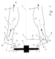
- FIG. 1 shows a longitudinal section along the axis 21 of a gas turbine.
- the entire three-dimensional combustion chamber structure is essentially obtained by rotating the section about axis 21, i.e. it deals the channeling components with the exception of the mixing tubes 22 Axially symmetrical parts about the axis 21 of the gas turbine.
- the hot one from the first Combustion chamber, the primary combustion chamber, escaping airflow flows at the shown gas turbine first via a first turbine 11, which in one Bearing 31 is stored.
- There is a short one downstream of the first turbine 11 hollow cylindrical discharge line 12 through which the air flow from the first Turbine 10 flows parallel to the axis 21 of the gas turbine.
- the outflow pipe 12 is preferably just long enough that the axial hollow cylindrical Flow profile in the airflow 10 can recover.
- Downstream of the discharge line 12 is a diffuser 13 in which the air flow is controlled by the axial direction is deflected. The deflection occurs after in Figure 1 outside in an almost radial direction, but it is also conceivable in principle that Distraction inside.
- the curvature of the diffuser 13 can with the help of the inverse Euler equations can be optimized. It is essentially in the diffuser 13 therefore, the average flow velocity of the air flow approximately cut in half.
- the diffuser 13 abuts a toroidal ring in a tangential manner downstream Chamber 14 to.
- the torus 14 is arranged perpendicular to the axis 21 of the generator, with a large torus radius 29 around axis 21, i.e. the major toric axis 27 and the axis 21 of the generator coincide.
- the circular line of the large torus radius 29 forms the annular torus minor axis 26, and the Torus outer wall 30 is formed by a small torus radius 28 around the ring Secondary torus axis 26 formed.
- a plurality are located downstream of the toroidal annular chamber 14 of mixing tubes 22 which are perpendicular to the toroidal secondary axis 26 of branch off the chamber 14 and are distributed over the circumference of the chamber 14. Through these mixing tubes 22, the air flow rolled up in the torus 14 flows out of the annular toroidal chamber 14 from.
- the mixing tubes 22 are cylindrical or at least partially conical and preferably have a radius in the area of the small torus radius 28.
- the actual combustion chamber 18, which again essentially as a hollow cylinder is formed around the axis 21, and downstream of this combustion chamber 18 is a second turbine arranged.
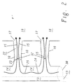
- Figure 2 shows part of a conical section through the chamber 14 and Mixing tubes 22 along the plane X-X in Figure 1 in view from the outside in.
- the behavior of the air flow in the chamber can be determined on the basis of this section 14 and the mixing tubes 22 illustrate.
- Air flow which is tangent to the center between two mixing tubes 22 Diffuser 13 enters the chamber 14, this separates into two to the left and vertebrae 24 and 25 evading to the right, which are different Screw direction, 24 corresponds to a left-handed screw, 25 a clockwise.
- Each of the partial vertebrae 24 and 25 now "screws" in Direction of the nearest mixing tube 22 to flow out of the chamber 14 there to be able to.
- Nozzles 32 are arranged with which liquid or gaseous Fuel can be injected.
- liquid Fuel can also be supplied through nozzles 20, which are located opposite the mixing tubes 22 Wall sides of the toroidal chamber 14 attached are injected into the air flow:
- nozzles 20 which are located opposite the mixing tubes 22
- Wall sides of the toroidal chamber 14 attached are injected into the air flow:
- Auto-ignition characteristic of the injected fuel according to the temperature of the Airflow and flow velocity are formed by auto-ignition of the mixture due to the high air temperature a flame front, which either at the area of the outlet of the mixing tubes 22 or behind it in the combustion chamber 18 can come to rest.
- a I u I A e u e .
- a I and A E are the cross-sectional areas of the tangential entry of the diffuser 13 into the annular toroidal chamber 14 and the cross-sectional area 23 of the mixing tubes 22, and u I and u E are the corresponding flow velocities.
- Table 1 gives the values for a secondary combustion chamber with 12 mixing tubes 22, each with an output radius of 300 mm.
- Size unit Value 1 Value 2 Large radius of the torus m 0.0675 0.0675 Small radius of the torus m 0.0275 0.0275 Width of the entry slot m 0.0085 0.0135 Radius of the tangential input m 0.04425 0.04675 Area of the entrance slot per swirl arm, A I m ⁇ 2 0.01182 0.001983 Eccentricity radius , r I m 0.02325 0.02075 Cross-sectional area of the vertebral arm, A E m ⁇ 2 0.002376 0.002376 vertebrae 1.70 0.90
Landscapes
- Engineering & Computer Science (AREA)
- Chemical & Material Sciences (AREA)
- Combustion & Propulsion (AREA)
- Mechanical Engineering (AREA)
- General Engineering & Computer Science (AREA)
- Fluidized-Bed Combustion And Resonant Combustion (AREA)
Description
Die vorliegende Erfindung bezieht sich auf das Gebiet der Gasturbinen. Sie betrifft eine Brennkammer für eine Gasturbine, in welcher Brennkammer Brennstoff mit einem in die Brennkammer eintretenden Luftstrom vermischt und anschliessend verbrannt wird, und der entstehende Verbrennungsluftstrom stromab der Brennkammer einer Turbine zugeführt wird. Eine solche Anordnung ist aus der Schrift US-A-3,877,219 bekannt.The present invention relates to the field of gas turbines. It affects a combustion chamber for a gas turbine, in which combustion chamber with fuel mixed with an air stream entering the combustion chamber and then is burned, and the resulting combustion air flow downstream of the combustion chamber is fed to a turbine. Such an arrangement is over the document US-A-3,877,219 known.
Gasturbinen werden heute häufig derart konstruiert, dass der hindurchgeführte Luftstrom durch zwei Brennkammern und entsprechend zweimal über Turbinen geleitet wird. Die angesaugte Luft wird dabei zunächst über eine Verdichtergruppe geführt, und anschliessend in eine Primärbrennkammer geleitet, wo zugeführtes Brennstoff-Luft-Gemisch gezündet und verbrannt wird. Aus der Primärbrennkammer strömt die heisse Verbrennungsluft über eine erste Turbine, und wird stromab der ersten Turbine einer Sekundärbrennkammer zugeführt, wo Brennstoff und nötigenfalls weitere Zuluft beigemischt wird und das Gemisch zündet. Da die aus der ersten Turbine ausströmenden Gase häufig sehr heiss, d.h. oberhalb der Selbstzündungstemperatur der Brennstoffe sind, kann in der Sekundärbrennkammer meist auf aktive Zündung verzichtet werden. Stromab der Sekundärbrennkammer befindet sich dann eine zweite Turbine, über welche die heissen Verbrennungsgase aus der Sekundärbrennkammer strömen.Today, gas turbines are often designed in such a way that the one passed through them Air flow through two combustion chambers and, accordingly, twice over turbines is directed. The air drawn in is initially passed through a compressor group led, and then passed into a primary combustion chamber, where supplied Fuel-air mixture is ignited and burned. From the primary combustion chamber the hot combustion air flows over a first turbine and becomes downstream fed to the first turbine of a secondary combustion chamber, where fuel and if necessary additional air is added and the mixture ignites. Since the from the gases escaping from the first turbine are often very hot, i.e. above the auto-ignition temperature of the fuels can be in the secondary combustion chamber mostly do without active ignition. Downstream of the secondary combustion chamber there is then a second turbine, over which the hot combustion gases flow out of the secondary combustion chamber.
Aus Platzgründen und zur technischen Vereinfachung werden bei derartigen Gasturbinen die einzelnen Komponenten meist in Serie entlang einer Hauptachse der Gasturbine angeordnet. Eine solche Gasturbogruppe ist beispielsweise aus der EP 0 620 362 A1 bekannt. Die einzelnen Kanäle für die Luftströme und die Brennkammern werden dabei meist alle im wesentlichen in Form von Hohlzylindern, welche um die Achse der Gasturbine herumgreifen, ausgebildet.For reasons of space and for technical simplification, such gas turbines the individual components usually in series along a major axis of the Gas turbine arranged. Such a gas turbine group is from, for example EP 0 620 362 A1 known. The individual channels for the air flows and the combustion chambers are mostly all in the form of hollow cylinders, which reach around the axis of the gas turbine.
Sekundärbrennkammern für derartige Gasturbinen sind in der Regel verhältnismässig einfach gestaltet, da sie keine Brenner benötigen, sondern der Brennstoff nach einer geeigneten Verwirbelung der aus der ersten Turbine austretenden heissen Luft einfach über Düsen in den Luftstrom eingedüst werden kann, und sich das Gemisch nach einer charakteristischen Zeit von selbst entzündet. Eine einfache, hohlzylindrisch ausgebildete Sekundärbrennkammer ist beispielsweise aus der EP 0 669 500 A1 bekannt.Secondary combustion chambers for such gas turbines are generally proportionate simply designed because they do not need burners, but the fuel after a suitable swirling of the hot ones emerging from the first turbine Air can simply be injected into the air flow via nozzles, and itself the mixture ignites itself after a characteristic time. A simple, the hollow-cylindrical secondary combustion chamber is, for example, out known from EP 0 669 500 A1.
Infolge der u.a. wegen der kurzen Selbstzündungszeiten von insbesondere gasförmigen Brennstoffen notwendigerweise hohen Machzahlen in Sekundäbrennkammern treten in diesen häufig thermoakkustische Oszillationen grosser Amplitude auf. Ausserdem stellt sich die Problematik der schnellen und effektiven Vermischung von Luft und Brennstoff in der Brennkammer unter Vermeidung von Strömungsrückfluss. Meist werden dazu spezifische wirbelerzeugende Elemente vorgesehen. Des weiteren muss insbesondere in neuerer Zeit bei der Vermischung und der Verbrennungsführung darauf geachtet werden, dass die Emissionswerte innerhalb gesetzlich zulässiger Schranken bleiben. As a result of because of the short auto-ignition times, especially of gaseous ones Fuels necessarily have high Mach numbers in secondary combustion chambers Frequently thermoacoustic oscillations of large amplitude occur in these on. There is also the problem of fast and effective mixing of air and fuel in the combustion chamber while avoiding Flow reflux. Usually, specific vortex-generating elements are used intended. Furthermore, especially in the more recent times, it must be mixed and the combustion management that the emission values remain within the legal limits.
Es ist daher Aufgabe der Erfindung, eine Brennkammer für Gasturbinen zu schaffen, welche Nachteile der bekannten Lösungen vermeidet und sich insbesondere durch gute und effiziente Vermischung von Brennstoff und zugeführter Luft auszeichnet.It is therefore an object of the invention to provide a combustion chamber for gas turbines, which disadvantages of the known solutions are avoided and in particular characterized by good and efficient mixing of fuel and supplied air.
Die Aufgabe wird bei einer Brennkammer der eingangs genannten Art dadurch gelöst, dass die Brennkammer einen ringförmigen Diffusor aufweist, in welchen der Luftstrom eintritt, dass stromab des Diffusors und mit diesem in Verbindung stehend mindestens eine im wesentlichen ringförmige toroidale Kammer angeordnet ist, dass stromab der ringförmigen toroidalen Kammer und über deren Umfang verteilt Mischröhren abzweigen, und dass stromab der Mischröhren ein ringförmiger Brennraum angeordnet ist, in welchen die Mischröhren einmünden. Der Kern der Erfindung besteht darin, durch die Kombination von Diffusor, ringförmig toroidaler Kammer und Mischröhren eine vormischende Struktur zur Verfügung zu stellen, in welcher sich hindurchströmende Luft in optimaler Weise, d.h. schnell und effizient mit Brennstoff vermischen lässt. Ein weiterer Vorteil ergibt sich daraus, dass die vorgeschlagene Konfiguration in reduziertem Masse zu thermoakkustischen Oszillationen neigt.The task is thereby in a combustion chamber of the type mentioned solved that the combustion chamber has an annular diffuser, in which the air flow enters that downstream of and in connection with the diffuser standing at least one substantially annular toroidal chamber arranged is that downstream of the annular toroidal chamber and over its circumference distributed mixing tubes branch, and that downstream of the mixing tubes an annular Combustion chamber is arranged, in which the mixing tubes open. The core the invention consists in the combination of diffuser, toroidal ring Chamber and mixing tubes have a premixing structure available too place in which air flowing through in an optimal manner, i.e. fast and can be mixed efficiently with fuel. Another advantage comes from that the proposed configuration is reduced to thermoacoustic Oscillations tend.
Eine erste bevorzugte Ausführungsform der erfindungsgemässen Brennkammer ist dadurch gekennzeichnet, dass die Brennkammer als Sekundärbrennkammer ausgelegt ist, und dass die Gasturbine eine Primärbrennkammer, eine stromab der Primärbrennkammer wirkende erste Turbine, eine stromab der ersten Turbine wirkende Sekundärbrennkammer, sowie eine stromab der Sekundärbrennkammer wirkende zweite Turbine aufweist. Der Einsatz der Brennkammer als Sekundärbrennkammer ist vorteilhaft, da gerade bei derartiger Verwendung bei hohen Machzahlen kurze Mischzeiten erforderlich sind. Insbesondere wenn die Zündung, wie in einer weiteren Ausführungsform beschrieben, in der Sekundärbrennkammer durch Selbstzündung erfolgt, ist das schnelle und rückstromfreie Mischen in der vorgeschlagenen Anordnung vorteilhaft, und es kann so eine kontrollierte Verbrennung im Bereich des Ausgangs der Mischröhren in den Brennraum oder im Brennraum gewährleistet werden. A first preferred embodiment of the combustion chamber according to the invention is characterized in that the combustion chamber as a secondary combustion chamber is designed, and that the gas turbine has a primary combustion chamber, a downstream the primary combustion chamber acting first turbine, a downstream of the first turbine acting secondary combustion chamber, and one downstream of the secondary combustion chamber has acting second turbine. The use of the combustion chamber as a secondary combustion chamber is advantageous, especially with such use at high Mach numbers short mixing times are required. Especially when the ignition, as described in a further embodiment, in the secondary combustion chamber is done by self-ignition, the quick and backflow-free mixing is in the proposed arrangement advantageous, and so it can controlled combustion in the area of the outlet of the mixing tubes in the combustion chamber or in Combustion chamber can be guaranteed.
Eine weitere bevorzugte Ausführungsform der Brennkammer nach der Erfindung zeichnet sich dadurch aus, dass der Diffusor derart ausgestaltet ist, dass der parallel zur Gasturbinenachse strömende und in die Brennkammer eintretende Luftstrom zunächst in im wesentlichen radiale Richtung abgelenkt wird, und dass der Diffusor in tangentialer Weise an die ringförmig toroidale Kammer angreift, so dass sich der in die ringförmig toroidale Kammer eintretende Luftstrom im Torus aufrollt und um die ringförmige Torusnebenachse wirbelt. Werden nun weiterhin bevorzugt die Mischröhren auf der im wesentlichen dem Diffusor entgegengesetzten Seite in im wesentlichen zur Achse der Gasturbine paralleler Weise angebracht, so treffen jeweils vor den Mischröhren zwei Wirbel unterschiedlichen Schraubendrehsinns aufeinander, und strömen dann unter gegenseitiger Vermischung und Vernichtung der Wirbel durch die Mischröhren. Dies ergibt die Möglichkeit, wie in einer weiteren Ausführungsform beschrieben, im oder vor dem Bereich dieser Vermischung der gegenläufigen Wirbel Mittel vorzusehen, mit welchen Brennstoff in den Luftstrom eingedüst werden kann. So kann der Mischprozess kurz gehalten und die Zündungsfront auf den gewünschten Ort eingestellt werden.Another preferred embodiment of the combustion chamber according to the invention is characterized in that the diffuser is designed such that the parallel air flow flowing to the gas turbine axis and entering the combustion chamber is initially deflected in a substantially radial direction, and that the Diffuser acts in a tangential manner on the toroidal chamber, so that the air flow entering the toroidal chamber curls up in the torus and swirls around the toroidal minor axis of the torus. Are now still preferred the mixing tubes on the one essentially opposite the diffuser Side attached in a manner essentially parallel to the axis of the gas turbine, In this way, two swirls of different screw rotation meet in front of the mixing tubes on top of each other, and then flow with mutual mixing and Annihilation of the vertebrae through the mixing tubes. This gives the possibility, as in another embodiment described in or in front of the area Mixing the opposite vortex means to provide with which fuel can be injected into the air flow. So the mixing process can be kept short and the ignition front can be set to the desired location.
Weitere bevorzugte Ausführungsformen der Brennkammer ergeben sich aus den abhängigen Ansprüchen.Further preferred embodiments of the combustion chamber result from the dependent claims.
Die Erfindung soll nachfolgend anhand von Ausführungsbeispielen im Zusammenhang mit den Zeichnungen näher erläutert werden. Es zeigen
- Fig. 1
- einen axialen Längsschnitt durch einen Teil einer Gasturbine mit Sekundärbrennkammer;
- Fig. 2
- eine Teilansicht eines Schnittes entlang der Konusebene X-X aus
Figur 1 in einer Ansicht von aussen nach innen; und - Fig. 3
- die Wirbelzahl (swirl number) als Funktion des kleinen Torusradius (small radius of torus) in Metern.
- Fig. 1
- an axial longitudinal section through part of a gas turbine with a secondary combustion chamber;
- Fig. 2
- a partial view of a section along the cone plane XX of Figure 1 in a view from the outside inwards; and
- Fig. 3
- the swirl number as a function of the small radius of torus in meters.
Die vorgeschlagene Gestaltung der Brennkammer beruht unter anderem auf dem spektakulären Vereinigungs- und Mischverhalten von kollidierenden, mit gegenläufig Drehsinn rotierenden, subkritischen Wirbeln. Dieses Phänomen wurde am Strömungsverhalten vor und in radialen Ausgangsrohren von Dampfturbinen entdeckt. Es zeigt sich nämlich dort, dass nur bei Anbringung von radialen Ausgangsrohren ein möglichst verlustfreies Ausströmen der rotierenden Luft möglich ist, während bei einfachen Öffnungen Verluste infolge von Verwirbelungen auftreten. Eine detaillierte Betrachtung des Verhaltens der Luftströmung vor und in einem solchen radialen Ausgangsrohr zeigt, dass vor den Rohren jeweils zwei mit gegenläufigem Drehsinn schraubend rotierende, subkritische Wirbel kollidieren, und sich die Rotation der zwei Wirbel innerhalb einer Distanz von weniger als einem Durchmesser des Ausgangsrohrs vollständig gegenseitig aufhebt.The proposed design of the combustion chamber is based, among other things, on the spectacular merging and mixing behavior of colliding, with opposing Rotating, rotating, subcritical vortices. This phenomenon occurred on Flow behavior in front of and in radial outlet pipes of steam turbines discovered. It is shown there that only when radial outlet pipes are attached the loss of free flow of the rotating air is possible, while losses occur due to swirling in simple openings. A detailed look at the behavior of the air flow before and in one Such a radial outlet tube shows that two in front of the tubes with opposite directions Rotating, rotating subcritical vortices collide, and the rotation of the two vertebrae within a distance of less than one Completely cancel each other out.
Während normalerweise bei Brennkammern und insbesondere bei Sekundärbrennkammern nach dem Stand der Technik wirbelerzeugende Elemente wie Verwirbelungsbleche oder Störungslufteintritte vorgesehen werden müssen, um eine schnelle und effektive Vermischung von Luft und Brennstoff zu gewährleisten, beruht die Vermischung in der vorgeschlagenen Brennkammer auf einer Strukturierung und Führung der Strömungskanäle, welche eine kontrollierte Wirbelbildung und Vermischung der hindurchströmenden Luft inhärent ergibt.While normally in combustion chambers and especially in secondary combustion chambers according to the prior art vortex generating elements such as Swirl plates or fault air inlets must be provided to to ensure a quick and effective mixing of air and fuel, the mixing in the proposed combustion chamber is based on a structuring and guiding the flow channels, which a controlled vortex formation and inherent mixing of the air flowing therethrough.
Das neue Konzept ist in Figur 1 anhand einer Sekundärbrennkammer schematisch
dargestellt. Figur 1 zeigt einen Längsschnitt entlang der Achse 21 einer Gasturbine.
Im wesentlichen erhält man dabei die gesamte dreidimensionale Brennkammerstruktur
indem man den Schnitt um die Achse 21 rotiert, d.h. es handelt
sich bei den Kanalisierungskomponenten mit ausnahme der Mischrohre 22 um
axialsymmetrische Teile um die Achse 21 der Gasturbine. Der heisse, aus der ersten
Brennkammer, der Primärbrennkammer, austretende Luftstrom strömt bei der
dargestellten Gasturbine zunächst über eine erste Turbine 11, welche in einem
Lager 31 gelagert ist. Stromab der ersten Turbine 11 befindet sich eine kurze
hohlzylindrische Ausströmleitung 12, durch welche der Luftstrom aus der ersten
Turbine 10 parallel zur Achse 21 der Gasturbine hindurchströmt. Die Ausströmleitung
12 ist dabei bevorzugt gerade so lang, dass sich das axiale hohlzylindrische
Strömungsprofil im Luftstrom 10 wieder erholen kann. Stromab der Ausströmleitung
12 befindet sich ein Diffusor 13, in welchem der Luftstrom kontrolliert von der
axialen Richtung abgelenkt wird. Die Ablenkung geschieht dabei in Figur 1 nach
aussen in beinahe radiale Richtung, es ist aber grundsätzlich auch denkbar, die
Ablenkung nach innen vorzunehmen. Die Kurvatur des Diffusors 13 kann mit Hilfe
der inversen Eulergleichungen optimiert werden. Es geht im Diffusor 13 im wesentlichen
darum, die mittlere Strömungsgeschwindigkeit des Luftstroms ungefähr
zu halbieren.The new concept is shown schematically in FIG. 1 using a secondary combustion chamber
shown. Figure 1 shows a longitudinal section along the
Der Diffusor 13 stösst stromabwärts in tangentialer Weise an eine ringförmig toroidale
Kammer 14 an. Der Torus 14 ist senkrecht zur Achse 21 des Generators angeordnet,
mit einem grossen Torusradius 29 um die Achse 21, d.h. die Torushauptachse
27 und die Achse 21 des Generators fallen zusammen. Die Kreislinie
des grossen Torusradius 29 bildet die ringförmige Torusnebenachse 26, und die
Torusaussenwand 30 wird durch einen kleinen Torusradius 28 um die ringförmige
Torusnebenachse 26 gebildet. Infolge des tangentialen Einströmens des Luftstroms
aus dem Diffusor 13 in die ringförmig toroidale Kammer 14 wird der Luftstrom
in kontrollierter Weise um die ringförmige Torusnebenachse 26 umgelenkt
und rollt sich in Form eines Torus nach innen auf, so wie das aus dem ersten Abschnitt
der Trajektorie 15 des Wirbelzentrums in Figur 1 ersichtlich ist.The
Stromabwärts der ringförmigen toroidalen Kammer 14 befinden sich eine Mehrzahl
von Mischröhren 22, welche senkrecht zur ringförmigen Torusnebenachse 26 von
der Kammer 14 abzweigen und auf dem Umfang der Kammer 14 verteilt sind.
Durch diese Mischröhren 22 strömt der im Torus 14 aufgerollte Luftstrom aus der
ringförmig toroidalen Kammer 14 ab. Die Mischröhren 22 sind zylindrisch oder
wenigstens teilweise konisch ausgebildet und weisen vorzugsweise einen Radius
im Bereich des kleinen Torusradius 28 auf. Stromab der Mischröhren 22 befindet
sich der eigentliche Brennraum 18, welcher wieder im wesentlichen als Hohlzylinder
um die Achse 21 ausgebildet ist, und stromab dieses Brennraums 18 ist eine
zweite Turbine angeordnet. A plurality are located downstream of the toroidal
Figur 2 zeigt einen Teil eines konischen Schnittes durch die Kammer 14 und die
Mischröhren 22 entlang der Ebene X-X in Figur 1 in Sicht von aussen nach innen.
Anhand dieses Schnittes lässt sich das Verhalten des Luftstromes in der Kammer
14 und den Mischröhren 22 illustrieren. Betrachtet man der Einfachheit halber den
Luftstrom, der genau mittig zwischen zwei Mischröhren 22 tangential aus dem
Diffusor 13 in die Kammer 14 eintritt, so trennt sich dieser in zwei nach links und
nach rechts ausweichende Wirbel 24 und 25 auf, welche unterschiedlichen
Schraubendrehsinn haben, 24 entspricht dabei einer linksdrehenden Schraube, 25
einer rechtsdrehenden. Jeder der Teilwirbel 24 und 25 "schraubt" sich nun in
Richtung der nächstgelegenen Mischröhre 22, um dort aus der Kammer 14 ausströmen
zu können. Wenn die geometrischen Abmessungen richtig gewählt werden,
findet Strömungsumkehr, wenn überhaupt, nur in den stromaufwärts der
Mischröhren 22 liegenden Bereichen der ringförmig toroidalen Kammer 14 auf.
Unmittelbar von den Mischröhren 22 treffen nun jeweils zwei mit unterschiedlichem
Schraubendrehsinn behaftete Wirbel aufeinander. Sobald die zwei Wirbelzentren
in die Mischröhren 22 eintreten, hört jede Strömungsumkehr auf, und es
bilden sich jet-artige Wirbelzentren. An einer bestimmten Stelle im Bereich des
Eingangs der Mischröhren nähern sich die gegenläufigen Wirbel maximal an und
genau in diesem Bereich setzt nun der heftige Vereinigungsprozess der beiden
Wirbel ein, wobei sich die Verwirbelung vollständig aufhebt. Diese vollständige
Aufhebung erfolgt üblicherweise innerhalb einer Distanz von weniger als einem
Durchmesser der Mischröhren 22, und sie bringt die vollständige Vermischung der
beiden Luftströme mit sich.Figure 2 shows part of a conical section through the
Gerade in dem Bereich, wo sich die beiden Wirbel maximal annähern, sollen vorteilhafterweise
Düsen 32 angeordnet werden, mit welchen flüssiger oder gasförmiger
Brennstoff eingedüst werden kann. Auf diese Weise wird eine optimale
Vermischung von Brennstoff und Luft unter sicheren Bedingungen erreicht. Flüssiger
Brennstoff kann auch durch Düsen 20, welche an der den Mischröhren 22 gegenüberliegenden
Wandungsseiten der ringförmig toroidalen Kammer 14 angebracht
sind, in den Luftstrom eingedüst werden: Je nach Ort der Eindüsung, nach
Selbstzündungscharakteristik des eingedüsten Brennstoffes, nach Temperatur des
Luftstromes und nach Strömungsgeschwindigkeit bildet sich durch Selbstzündung
des Gemisches infolge der hohen Lufttemperatur eine Flammenfront, welche entweder
beim Bereich des Ausgangs der Mischröhren 22 oder dahinter im Brennraum
18 zu liegen kommen kann.Especially in the area where the two vertebrae approach each other to a maximum, should advantageously
Nozzles 32 are arranged with which liquid or gaseous
Fuel can be injected. In this way, an optimal
Mixing of fuel and air achieved under safe conditions. liquid
Fuel can also be supplied through
Um die Dimensionierung der einzelnen Komponenten gezielt optimieren zu können,
ist es vorteilhaft, die Wirbelzahländerungen des vorliegenden Konzeptes mit
denjenigen solcher Bauarten zu vergleichen, für welche experimentelle Daten vorhanden
sind. Die für die Kollision von subkritischen Wirbeln relevante Wirbelzahl
kann folgendermassen gefunden werden. Erhaltung des Volumenflusses verlangt,
dass gilt
Entsprechend kann die Wirbelzahl ξ der kollidierenden Wirbel ausgedrückt werden
als
Tabelle 1 gibt die Werte für eine Sekundärbrennkammer mit 12 Mischröhren 22
mit jeweils einem Ausgangsradius von 300mm. Der grosse Radius der Ausgänge
der über die Kammer 14 kreisförmig um die Achse 21 verteilten Mischröhren 22 ist
dabei 1161 mm, was eine umfangsmässige Beabstandung der Mischröhren von
etwas mehr als zweimal einem Mischröhrendurchmesser ergibt.
Vergleicht man den in Tabelle 1 gegebenen Wert für die Wirbelzahl von 1.08 mit den in Tabelle 2 gegebenen experimentellen Werten für Ausgänge von Dampfturbinen, so sieht man, dass dort Wirbelzahlen von 0.9 bis 1.7 auftreten. Im Fall eines "twin-combustor" der Anmelderin, mit einer Fläche des Eingangsschlitzes pro Wirbelarm, AI , von 0.010278m2, einem Exzentrizitätsradius, rI , von 0.04375m und einer Querschnittsfläche des Wirbelarms, AE , von 0.047144m2 tritt eine hohe Wirbelzahl von ξ =1.64 auf.If you compare the value given in Table 1 for the vortex number of 1.08 with the experimental values given in Table 2 for steam turbine outputs, you can see that vortex numbers from 0.9 to 1.7 occur there. In the case of a "twin combustor" of the applicant, with an area of the entry slot per vertebral arm, A I , of 0.010278m 2 , an eccentricity radius , r I , of 0.04375m and a cross-sectional area of the vertebral arm, A E , of 0.047144m 2 occurs a high vortex number of ξ = 1.64.
Um einen optimalen Kompromiss zwischen schnellem Mischen und relativ unwichtigen
Domänen von Strömungsumkehr stromaufwärts des Wirbelzentrums zu
haben, sollte die Wirbelzahl ξ im Bereich von 1 liegen. Die wohl beste Strategie
dafür ist die Variation des kleinen Torusradius 28 stromaufwärts der Mischröhren
22, wobei man mit einem Startwert von 150mm beginnen kann. Figur 3 zeigt die
Wirbelzahl (swirl number) als Funktion des kleinen Torusradius' 28 (small radius of
torus) in Metern, wobei alle anderen Werte gleich gehalten werden wie in Tabelle
1 gegeben. Man sieht, dass sich die Wirbelzahl stark ändern lässt, indem man den
kleinen Torusradius 28 variiert, erfahrungsgemäss zeigt es sich, dass optimalerweise
der kleine Torusradius 28 nicht stark vom typischen Mischröhrenradius abweichen
sollte.An optimal compromise between fast mixing and relatively unimportant
Domains of flow reversal upstream of the vortex center
the vertebra number ξ should be in the range of 1. Probably the best strategy
this is the variation of the
- 1010
- Luftstrom aus erster TurbineAirflow from the first turbine
- 1111
- erste Turbinefirst turbine
- 1212
- Ausstömleitung der ersten TurbineBlow-out line of the first turbine
- 1313
- Diffusordiffuser
- 1414
- ringförmig toroidale Kammertoroidal chamber
- 1515
- Trajektorie des WirbelzentrumsTrajectory of the vertebral center
- 1616
- Wandung der MischröhreWall of the mixing tube
- 1717
- Ausgang der MischröhreOutput of the mixing tube
- 1818
- Brennraumcombustion chamber
- 1919
- Ausgang von 18 zur zweiten Turbine Exit from 18 to the second turbine
- 2020
- Einspritzdüse für flüssigen BrennstoffLiquid fuel injector
- 2121
- Achse der GasturbineAxis of the gas turbine
- 2222
- Mischröhremixing tube
- 2323
- Querschnittsfläche der MischröhreCross-sectional area of the mixing tube
- 24,2524.25
- gegenläufig rotierende Teilströme des Luftstromscounter-rotating partial flows of the air flow
- 2626
- TorusnebenachseTorusnebenachse
- 2727
- TorushauptachseTorushauptachse
- 2828
- kleiner Torusradiussmall torus radius
- 2929
- grosser Torusradiuslarge torus radius
- 3030
- TorusaussenwandTorusaussenwand
- 3131
- Lager der ersten TurbineBearings of the first turbine
- 3232
- Einspritzdüsen für BrennstoffInjectors for fuel
- 3333
- VerbrennungsluftstromCombustion air flow
Claims (12)
- Combustion chamber (13, 14, 18, 22) for a gas turbine, in which combustion chamber (13, 14, 18, 22) fuel is mixed with an air flow (10) entering the combustion chamber (13, 14, 18, 22) and is subsequently burned, and the combustion-air flow (33) produced is fed to a turbine downstream of the combustion chamber (13, 14, 18, 22), characterized in that the combustion chamber (13, 14, 18, 22) has an annular diffuser (13), which the air flow (10) enters, in that at least one essentially annular toroidal chamber (14) is arranged downstream of the diffuser (13) and in such a way as to be connected to the latter, in that mixing tubes (22) branch off downstream of the annular toroidal chamber (14) and in such a way as to be distributed over the periphery of the latter, and in that an annular combustion space (18) into which the mixing tubes (22) open is arranged downstream of the mixing tubes (22).
- Combustion chamber (13, 14, 18, 22) according to Claim 1, characterized in that the combustion chamber is designed as a secondary combustion chamber (13, 14, 18, 22), and in that the gas turbine has a primary combustion chamber, a first turbine (11) acting downstream of the primary combustion chamber, a secondary combustion chamber (13, 14, 18, 22) acting downstream of the first turbine (11), and a second turbine acting downstream of the secondary combustion chamber (13, 14, 18, 22).
- Combustion chamber (13, 14, 18, 22) according to Claim 2, characterized in that the annular toroidal chamber (14) has an annular torus minor axis (26) which runs with a large radius (29) of torus about a torus major axis (27), and in which annular toroidal chamber (14) a torus outer wall (30) with a small radius (28) of torus is formed about the torus minor axis (26), and in that the torus major axis (27) is oriented essentially parallel to the axis (21) of the gas turbine.
- Combustion chamber (13, 14, 18, 22) according to Claim 3, characterized in that the mixing tubes (22) are designed to be essentially conical or cylindrical, and in that the axes of the mixing tubes (22) are arranged outside the plane of the annular toroidal chamber (14) and essentially perpendicularly to the annular torus minor axis (26).
- Combustion chamber (13, 14, 18, 22) according to Claim 3, characterized in that the radius of the mixing tubes (22) is formed in the region of the small radius (28) of torus or is preferably formed to be the same as the small radius (28) of torus.
- Combustion chamber (13, 14, 18, 22) according to either of Claims 4 or 5, characterized in that the primary combustion chamber is an annular combustion chamber, in that an outflow line (12) designed as a hollow cylinder is arranged between the first turbine (11) and the diffuser (13), and in that the axis of the outflow line (12) runs parallel to the axis (21) of the gas turbine.
- Combustion chamber (13, 14, 18, 22) according to Claim 6, characterized in that the annular diffuser (13) is designed in such a way that the air flow (10) flowing through the outflow line (12) parallel to the axis (21) of the gas turbine is deflected by the diffuser (13), and in that in particular this deflection is preferably effected in a direction running essentially radially to the axis (21) of the gas turbine.
- Combustion chamber (13, 14, 18, 22) according to either of Claims 6 or 7, characterized in that the diffuser (13) acts tangentially on the annular toroidal chamber (14).
- Combustion chamber (13, 14, 18, 22) according to Claim 8, characterized in that the diffuser (13) is designed in such a way that the air flow (10) is diverted by the diffuser (13) essentially radially outwards, and in that the diffuser (13) acts tangentially from inside on the annular toroidal chamber (14).
- Combustion chamber (13, 14, 18, 22) according to either of Claims 8 or 9, characterized in that the mixing tubes (16) are arranged essentially opposite the inlet opening of the diffuser (13) into the annular toroidal chamber (14), and in that they are oriented essentially parallel to the axis (21) of the gas turbine.
- Combustion chamber (13, 14, 18, 22) according to Claim 10, characterized in that means (20, 32) with which liquid fuel can be injected are arranged either on the rear side, remote from the mixing tubes (16), of the annular toroidal chamber (14) or in the central region of the mixing tubes (16) downstream of the annular toroidal chamber (14).
- Combustion chamber (13, 14, 18, 22) according to either of Claims 10 or 11, characterized in that means (32) via which gaseous fuel can be injected are arranged in the central region of the mixing tubes (16) downstream of the annular toroidal chamber (14).
Applications Claiming Priority (2)
| Application Number | Priority Date | Filing Date | Title |
|---|---|---|---|
| DE19860583 | 1998-12-29 | ||
| DE19860583A DE19860583A1 (en) | 1998-12-29 | 1998-12-29 | Combustion chamber for a gas turbine |
Publications (3)
| Publication Number | Publication Date |
|---|---|
| EP1016830A2 EP1016830A2 (en) | 2000-07-05 |
| EP1016830A3 EP1016830A3 (en) | 2002-07-24 |
| EP1016830B1 true EP1016830B1 (en) | 2004-05-26 |
Family
ID=7893029
Family Applications (1)
| Application Number | Title | Priority Date | Filing Date |
|---|---|---|---|
| EP99811182A Expired - Lifetime EP1016830B1 (en) | 1998-12-29 | 1999-12-21 | Gas turbine combustor |
Country Status (3)
| Country | Link |
|---|---|
| US (1) | US6272864B1 (en) |
| EP (1) | EP1016830B1 (en) |
| DE (2) | DE19860583A1 (en) |
Families Citing this family (2)
| Publication number | Priority date | Publication date | Assignee | Title |
|---|---|---|---|---|
| US11175046B2 (en) | 2019-05-09 | 2021-11-16 | General Electric Company | Combustor premixer assembly including inlet lips |
| CN116892736B (en) * | 2023-07-10 | 2025-10-17 | 中国人民解放军空军工程大学 | Distributed oil injection device and method for rotary detonation combustion chamber |
Family Cites Families (16)
| Publication number | Priority date | Publication date | Assignee | Title |
|---|---|---|---|---|
| DE1011670B (en) * | 1955-06-03 | 1957-07-04 | H C Ernst Schmidt Dr Ing Dr Re | Annular mixing or combustion chamber, especially for gas turbines |
| US3309866A (en) * | 1965-03-11 | 1967-03-21 | Gen Electric | Combustion process and apparatus |
| DE2232025A1 (en) * | 1972-06-30 | 1974-01-17 | Motoren Turbinen Union | GAS TURBINE SYSTEM, IN PARTICULAR ENGINE WITH COUNTER-ROOM COMBUSTION |
| US4081957A (en) * | 1976-05-03 | 1978-04-04 | United Technologies Corporation | Premixed combustor |
| US4073137A (en) * | 1976-06-02 | 1978-02-14 | United Technologies Corporation | Convectively cooled flameholder for premixed burner |
| GB2098719B (en) * | 1981-05-20 | 1984-11-21 | Rolls Royce | Gas turbine engine combustion apparatus |
| DE3661224D1 (en) * | 1985-02-26 | 1988-12-22 | Bbc Brown Boveri & Cie | Gas turbine combustor |
| JPS62158927A (en) | 1986-01-07 | 1987-07-14 | Nissan Motor Co Ltd | Annular burner |
| US4838029A (en) * | 1986-09-10 | 1989-06-13 | The United States Of America As Represented By The Secretary Of The Air Force | Externally vaporizing system for turbine combustor |
| CH679799A5 (en) * | 1988-07-25 | 1992-04-15 | Christian Reiter | |
| DE3942042A1 (en) * | 1989-12-20 | 1991-06-27 | Bmw Rolls Royce Gmbh | COMBUSTION CHAMBER FOR A GAS TURBINE WITH AIR SUPPORTED FUEL SPRAYER NOZZLES |
| DE4236071C2 (en) * | 1992-10-26 | 2002-12-12 | Alstom | Method for multi-stage combustion in gas turbines |
| US5575153A (en) * | 1993-04-07 | 1996-11-19 | Hitachi, Ltd. | Stabilizer for gas turbine combustors and gas turbine combustor equipped with the stabilizer |
| CH687269A5 (en) | 1993-04-08 | 1996-10-31 | Abb Management Ag | Gas turbine group. |
| CA2141066A1 (en) * | 1994-02-18 | 1995-08-19 | Urs Benz | Process for the cooling of an auto-ignition combustion chamber |
| EP0870990B1 (en) * | 1997-03-20 | 2003-05-07 | ALSTOM (Switzerland) Ltd | Gas turbine with toroidal combustor |
-
1998
- 1998-12-29 DE DE19860583A patent/DE19860583A1/en not_active Withdrawn
-
1999
- 1999-12-21 EP EP99811182A patent/EP1016830B1/en not_active Expired - Lifetime
- 1999-12-21 DE DE59909580T patent/DE59909580D1/en not_active Expired - Fee Related
- 1999-12-23 US US09/470,964 patent/US6272864B1/en not_active Expired - Fee Related
Also Published As
| Publication number | Publication date |
|---|---|
| DE59909580D1 (en) | 2004-07-01 |
| US6272864B1 (en) | 2001-08-14 |
| EP1016830A2 (en) | 2000-07-05 |
| DE19860583A1 (en) | 2000-07-06 |
| EP1016830A3 (en) | 2002-07-24 |
Similar Documents
| Publication | Publication Date | Title |
|---|---|---|
| DE60007946T2 (en) | A combustion chamber | |
| EP0675322B1 (en) | Premix burner | |
| EP0918191B1 (en) | Burner for the operation of a heat generator | |
| EP1141628B1 (en) | Burner for heat generator | |
| EP0718561B1 (en) | Combustor | |
| EP1828684A1 (en) | Premix burner comprising a mixing section | |
| EP0481111B1 (en) | Gas-turbine combustion chamber | |
| EP0777081B1 (en) | Premix burner | |
| DE2404039A1 (en) | IMPROVED FUEL INJECTION DEVICE | |
| EP1807656B1 (en) | Premix burner | |
| DE19640198A1 (en) | Premix burner | |
| EP0401529A1 (en) | Gas turbine combustion chamber | |
| EP0851172B1 (en) | Burner and method for operating a combustion chamber with a liquid and/or gaseous fuel | |
| EP1182398A1 (en) | Process for increasing the fluidic stability of a premix-burner as well as premix-burner for carrying out said process | |
| EP0994300B1 (en) | Burner for operating a heat generator | |
| EP0909921B1 (en) | Burner for operating a heat generator | |
| DE19527453B4 (en) | premix | |
| EP0394800A1 (en) | Premix burner for generating a hot gas | |
| EP0751351B1 (en) | Combustion chamber | |
| EP0483554B1 (en) | Method for minimising the NOx emissions from a combustion | |
| EP0742411A2 (en) | Air supply for a premix combustor | |
| EP0740108A2 (en) | Burner | |
| DE19537636B4 (en) | Power plant | |
| EP0882932B1 (en) | Combustor | |
| EP1016830B1 (en) | Gas turbine combustor |
Legal Events
| Date | Code | Title | Description |
|---|---|---|---|
| PUAI | Public reference made under article 153(3) epc to a published international application that has entered the european phase |
Free format text: ORIGINAL CODE: 0009012 |
|
| AK | Designated contracting states |
Kind code of ref document: A2 Designated state(s): AT BE CH CY DE DK ES FI FR GB GR IE IT LI LU MC NL PT SE |
|
| AX | Request for extension of the european patent |
Free format text: AL;LT;LV;MK;RO;SI |
|
| RAP1 | Party data changed (applicant data changed or rights of an application transferred) |
Owner name: ALSTOM |
|
| PUAL | Search report despatched |
Free format text: ORIGINAL CODE: 0009013 |
|
| AK | Designated contracting states |
Kind code of ref document: A3 Designated state(s): AT BE CH CY DE DK ES FI FR GB GR IE IT LI LU MC NL PT SE |
|
| AX | Request for extension of the european patent |
Free format text: AL;LT;LV;MK;RO;SI |
|
| RIC1 | Information provided on ipc code assigned before grant |
Free format text: 7F 23R 3/42 A, 7F 23R 3/02 B, 7F 23R 3/52 B, 7F 02C 6/00 B |
|
| RAP1 | Party data changed (applicant data changed or rights of an application transferred) |
Owner name: ALSTOM (SWITZERLAND) LTD |
|
| 17P | Request for examination filed |
Effective date: 20030109 |
|
| AKX | Designation fees paid |
Designated state(s): DE GB |
|
| 17Q | First examination report despatched |
Effective date: 20030401 |
|
| GRAP | Despatch of communication of intention to grant a patent |
Free format text: ORIGINAL CODE: EPIDOSNIGR1 |
|
| RAP1 | Party data changed (applicant data changed or rights of an application transferred) |
Owner name: ALSTOM TECHNOLOGY LTD |
|
| GRAS | Grant fee paid |
Free format text: ORIGINAL CODE: EPIDOSNIGR3 |
|
| GRAA | (expected) grant |
Free format text: ORIGINAL CODE: 0009210 |
|
| AK | Designated contracting states |
Kind code of ref document: B1 Designated state(s): DE GB |
|
| REG | Reference to a national code |
Ref country code: GB Ref legal event code: FG4D Free format text: NOT ENGLISH |
|
| REG | Reference to a national code |
Ref country code: IE Ref legal event code: FG4D Free format text: GERMAN |
|
| REF | Corresponds to: |
Ref document number: 59909580 Country of ref document: DE Date of ref document: 20040701 Kind code of ref document: P |
|
| GBT | Gb: translation of ep patent filed (gb section 77(6)(a)/1977) |
Effective date: 20040812 |
|
| REG | Reference to a national code |
Ref country code: IE Ref legal event code: FD4D |
|
| PLBE | No opposition filed within time limit |
Free format text: ORIGINAL CODE: 0009261 |
|
| STAA | Information on the status of an ep patent application or granted ep patent |
Free format text: STATUS: NO OPPOSITION FILED WITHIN TIME LIMIT |
|
| 26N | No opposition filed |
Effective date: 20050301 |
|
| PGFP | Annual fee paid to national office [announced via postgrant information from national office to epo] |
Ref country code: DE Payment date: 20081219 Year of fee payment: 10 |
|
| PGFP | Annual fee paid to national office [announced via postgrant information from national office to epo] |
Ref country code: GB Payment date: 20081216 Year of fee payment: 10 |
|
| GBPC | Gb: european patent ceased through non-payment of renewal fee |
Effective date: 20091221 |
|
| PG25 | Lapsed in a contracting state [announced via postgrant information from national office to epo] |
Ref country code: DE Free format text: LAPSE BECAUSE OF NON-PAYMENT OF DUE FEES Effective date: 20100701 |
|
| PG25 | Lapsed in a contracting state [announced via postgrant information from national office to epo] |
Ref country code: GB Free format text: LAPSE BECAUSE OF NON-PAYMENT OF DUE FEES Effective date: 20091221 |