EP1016325B1 - Mikrowellenofen - Google Patents
Mikrowellenofen Download PDFInfo
- Publication number
- EP1016325B1 EP1016325B1 EP98905388A EP98905388A EP1016325B1 EP 1016325 B1 EP1016325 B1 EP 1016325B1 EP 98905388 A EP98905388 A EP 98905388A EP 98905388 A EP98905388 A EP 98905388A EP 1016325 B1 EP1016325 B1 EP 1016325B1
- Authority
- EP
- European Patent Office
- Prior art keywords
- cavity
- section
- side wall
- cross
- microwave oven
- Prior art date
- Legal status (The legal status is an assumption and is not a legal conclusion. Google has not performed a legal analysis and makes no representation as to the accuracy of the status listed.)
- Expired - Lifetime
Links
- 230000003247 decreasing effect Effects 0.000 claims abstract description 9
- 238000000034 method Methods 0.000 claims abstract description 8
- 230000007423 decrease Effects 0.000 claims description 5
- 230000000694 effects Effects 0.000 claims description 3
- 238000010438 heat treatment Methods 0.000 abstract description 21
- 238000004519 manufacturing process Methods 0.000 description 4
- 238000012986 modification Methods 0.000 description 2
- 230000004048 modification Effects 0.000 description 2
- 238000013459 approach Methods 0.000 description 1
- 238000013461 design Methods 0.000 description 1
- 238000009826 distribution Methods 0.000 description 1
- 238000004049 embossing Methods 0.000 description 1
- 238000005304 joining Methods 0.000 description 1
- 230000003287 optical effect Effects 0.000 description 1
- 238000012360 testing method Methods 0.000 description 1
Images

Classifications
-
- H—ELECTRICITY
- H05—ELECTRIC TECHNIQUES NOT OTHERWISE PROVIDED FOR
- H05B—ELECTRIC HEATING; ELECTRIC LIGHT SOURCES NOT OTHERWISE PROVIDED FOR; CIRCUIT ARRANGEMENTS FOR ELECTRIC LIGHT SOURCES, IN GENERAL
- H05B6/00—Heating by electric, magnetic or electromagnetic fields
- H05B6/64—Heating using microwaves
- H05B6/6426—Aspects relating to the exterior of the microwave heating apparatus, e.g. metal casing, power cord
-
- H—ELECTRICITY
- H05—ELECTRIC TECHNIQUES NOT OTHERWISE PROVIDED FOR
- H05B—ELECTRIC HEATING; ELECTRIC LIGHT SOURCES NOT OTHERWISE PROVIDED FOR; CIRCUIT ARRANGEMENTS FOR ELECTRIC LIGHT SOURCES, IN GENERAL
- H05B6/00—Heating by electric, magnetic or electromagnetic fields
- H05B6/64—Heating using microwaves
- H05B6/80—Apparatus for specific applications
Definitions
- the present invention relates to a microwave oven and feeding of the same with microwaves.
- Microwave ovens for domestic use and the like are usually made with an essentially rectangularly parallelepipedal cavity. This is due to both manufacturing considerations and a conventional view of what microwave ovens should look like. Although it is possible to a certain extent to calculate which so-called cavity modes are obtained in a rectangularly parallelepipedal cavity, it has proved difficult to achieve a reasonably symmetrical heating pattern in such a cavity, in particular when it is fed sideways. So-called field stirrers or rotating bottom plates for the load are often employed with a view to improving the heating pattern.
- An object of the present invention is to make possible an improved heating pattern in a rectangularly parallelepipedal cavity in a microwave oven.
- Another object of the invention is to make possible such an improved heating pattern without employing moving parts, such as field stirrers or rotating bottom plates.
- a further object of the invention is to provide a method which allows improved configuration of a rectangularly parallelepipedal cavity with respect to the resulting heating pattern.
- the heating pattern in a rectangularly parallelepipedal oven cavity can be advantageously affected by the arrangement of a non-constant horizontal cross-section in the cavity.
- the cross-section changes concerned do not change the general rectangularly parallelepipedal shape and cannot be compared to wall embossing, rounding of corners, etc. which are conventionally done in order to adjust the rectangularly parallelepipedal dimensions for manufacturing reasons and generally to facilitate the manufacture of the cavity and improve mechanical stability.
- the invention is thus based on the insight that the relative phase and amplitude of the modes in the cavity can be modified favourably in and for heating pattern levelling-out or equalisation by means of well-judged, relatively modest vertical changes to the horizontal cross-section of the cavity. Put another way, by making these kinds of cross-section changes, one can control the mode balance with respect to both relative amplitudes and phase of the modes involved so that a more even heating pattern is achieved.
- the cross-section change can be achieved by a cavity side wall being made at least partly inward sloping.
- a method for microwave feeding of a rectangularly parallelepipedal microwave oven cavity which means that in and for equalisation of the effect of the microwaves in the cavity, the mode balance of the microwave field is affected by the cavity being given, in relation to the horizontal cavity bottom cross-section, at least in the upper part of the cavity an upwardly decreasing horizontal cross-section.
- the feeding of microwaves is advantageously done through an opening in a cavity side wall opposing the inward sloping wall, the microwave feeding preferably taking place along an area closely adjacent to the cavity ceiling.
- microwaves through an opening in the cavity ceiling, also in this case suitably extended in a direction parallel to the sloping side wall.
- a method for acting on the heating pattern which is obtained by means of microwaves fed into an rectangularly parallelepipedal microwave oven cavity, changes to the heating pattern being achieved by a cavity side wall being caused to slope inwards at least in its upper part, so that the cavity has an upwardly decreasing horizontal cross-section in relation to the available bottom cross-section of the cavity.
- a chosen cavity width it is possible on the basis of a chosen cavity width to vary the horizontal cross-section change by changing the degree and/or extent of the inward slope of the cavity wall and observing the resulting changes to the heating pattern. It will be appreciated that by carrying out such changes of the inward slope of the side wall for a number of different cavity widths, it is possible to determine the cavity width and side wall inward slope combination which provides the best heating pattern.
- a microwave oven comprising a rectangularly parallelepipedal cavity and a microwave source connected thereto for feeding microwaves into the cavity, the cavity, in relation to its available bottom cross-section, having an upwardly decreasing horizontal cross-section at least in the upper part of the cavity.
- the cavity preferably has a side wall, which at least partly slopes inwards in order to provide the desired horizontal cross-section decrease.
- the inward slope is in the upper part of the side wall, while the lower part of the side wall is vertical and preferably at least 50 mm high.
- the inward slope of the upper part of the side wall does not need to extend all the way up to the cavity ceiling, rather the side wall can have a short vertical ceiling connection part terminating at the top.
- the sloping side wall part is plane, other configurations are also possible.
- the slope of the side wall is preferably over essentially the whole actual wall width and advantageously over at least about half the wall height.
- the slope of the side wall can be made within a deep-drawn portion of the side wall, so that the joining with the back wall and the front of the oven can be done with vertical joints.
- the slope can advantageously be over about 85% of the total depth of the cavity.
- a microwave oven according to the invention suitably has a horizontal cross-section which is approximately square.
- the "depth” is preferably between about 85% and about 120% of the "width”.
- the height of the cavity from the bottom plate or the cavity bottom to the cavity colling is from about 160 mm to about 230 mm.
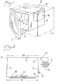
- the embodiment of a microwave oven according to the invention illustrated in Figs 1 and 2 comprises an outer casing 1 which is outlined only and an oven cavity 2, which is closed by means of a front door 3.
- the cavity 2 is formed by a horizontal cavity bottom 4, a horizontal cavity ceiling 5, a vertical back cavity wall 6, a front vertical wall on the inside of the front door 3 and two cavity side walls 7 and 8.
- the right side wall 7 in Figs 1 and 2 is vertical and provided with a microwave unit for feeding microwaves into the oven cavity through a slot-shaped, rectangular side wall opening 10, such as will be described in more detail below.
- the left side wall 8 in Figs 1 and 2 slopes inward somewhat and thus forms an angle of about 3° to vertical. Consequently, the cavity is rectangularly parallelepipedal except for the inward slope of the side wall 8. However, the inward slope is so small that it cannot be considered that there is any essential deviation from the rectangularly parallelepipedal shape, except for the resulting microwave characteristics.
- All the cavity defining wall surfaces in this embodiment are generally plane, although the sloping side wall 8 joins the cavity ceiling at the top with a vertical wall part 11 of a small height.
- the microwave unit 9 comprises in a manner known per se a magnetron 13 and a waveguide device 14 connected thereto for feeding microwaves into the cavity through the feeder slot 10.
- this slot is usually elongated and rectangular and arranged at the top and in the midpoint on the side wall 7 in the connection area to the cavity ceiling 5.
- the oven can comprise a microwave-transparent bottom plate 16 for a foodstuff load 17. If desired, this plate can be rotatable. However, it has been found that the oven constructed according to the invention despite the sideways feeding of microwaves gives a heating pattern which is so even that a rotating bottom plate cannot be considered necessary.
- Examples of typical dimensions for an oven for domestic use according to Figs 1 and 2 are B1 - about 333 mm, B2 - about 325 mm; cavity height (over the bottom plate) - about 185 mm; and cavity depth - about 370 mm.
- Fig. 3 shows a schematic vertical cross-section of the same kind as in Fig. 2, which illustrates another embodiment of an oven according to t.he invention. The latter differs from the oven according Lo Figs 1 and 2 with respect to the design of the sloping side wall and the microwave feeding.
- the sloping side wall 8' in Fig. 2 has a lower part 21, which is vertical, and an upper inward-sloping part 22.
- the inward slope begins about halfway up the side wall and amounts to about 6°.
- the horizontal cross-section decrease adjacent to the cavity ceiling is here somewhat larger than in the oven according to Figs 1 and 2, typically about 10 mm.
- Fig. 3 the microwave feeding is done through a rectangular ceiling slot 10', which is centrally located in the cavity ceiling 5 and whose long side is parallel to the cavity side walls 7 and 8' and which is fed by the intermediary of a waveguide device 14' arranged on the cavity ceiling.
Landscapes
- Physics & Mathematics (AREA)
- Electromagnetism (AREA)
- Constitution Of High-Frequency Heating (AREA)
- Electric Ovens (AREA)
Claims (10)
- Mikrowellenofen, umfassend einen rechteckigen, parallelepipeden Hohlraum sowie eine Mikrowellenquelle zum Zuführen von Mikrowellen in den Hohlraum (2), die damit verbunden ist, dadurch gekennzeichnet, dass der Hohlraum in Bezug auf seinen Bodenquerschnitt einen nach oben hin kleiner werdenden horizontalen Querschnitt aufweist und der Hohlraum außer in Bezug auf die Innenneigung einer Hohlraum-Seitenwand nahe einer vorderen vertikalen Wand an der Innenseite einer Vordertür (3) ein rechteckiges Parallelepiped ist, wobei die Innenneigung auf halber Höhe der Seitenwände (8, 8') beginnt.
- Mikrowellenofen gemäß Anspruch 1, dadurch gekennzeichnet, dass eine Hohlraum-Seitenwand (7), die der geneigten Seitenwand (8, 8') gegenübersteht, mit zumindest einer an der Oberseite platzierten Schlitzöffnung (10) für die Zufuhr von Mikrowellen versehen ist.
- Mikrowellenofen gemäß Anspruch 1 oder 2, dadurch gekennzeichnet, dass er mit einer Schlitzöffnung (10') in der Hohlraumdecke (5) zur Zufuhr von Mikrowellen versehen ist, wobei sich die Schlitzöffnung transversal zu einer vertikalen Ebene, in der die horizontale Breite des Hohlraums nach oben hin abnimmt, erstreckt.
- Mikrowellenofen gemäß einem der Ansprüche 1 bis 3, dadurch gekennzeichnet, dass der horizontale Querschnitt des Hohlraums eine Tiefe aufweist, die von etwa 85% bis zu etwa 120% der Breite entspricht.
- Mikrowellenofen gemäß einem der Ansprüche 1 bis 4, dadurch gekennzeichnet, dass die Querschnittsbreite oben im Hohlraum (2) im Intervall von etwa 315 mm bis zu etwa 335 mm liegt und dass die Querschnittsbreite von etwa 8 bis etwa 15 mm größer als der Boden ist.
- Mikrowellenofen gemäß einem der Ansprüche 1 bis 5, dadurch gekennzeichnet, dass die Querschnittsbreite oben im Hohlraum (2) im Intervall von etwa 385 mm bis etwa 410 mm liegt und dass die Querschnittsbreite von etwa 8 bis etwa 15 mm größer als der Boden ist.
- Mikrowellenofen gemäß Anspruch 5 oder 6, dadurch gekennzeichnet, dass der Hohlraum (2) eine Höhe von etwa 150 mm bis etwa 220 mm aufweist.
- Verfahren zur Zufuhr von Mikrowellen in einen rechteckigen, parallelepipeden Mikrowellenofen-Hohlraum, dadurch gekennzeichnet, dass in und zum Ausgleich des Effekts der Mikrowellen im Hohlraum das Modus-Gleichgewicht des Mikrowellenfelds durch den vorgegebenen Hohlraum in Bezug auf den horizontalen Querschnitt des Hohlraumbodens und eines nach oben hin abnehmenden horizontalen Querschnitt zumindest im oberen Teil des Hohlraums beeinflusst wird, wobei der abnehmende horizontale Querschnitt durch eine Innenneigung der Hohlraum-Seitenwand (8, 8') zumindest ab der halben Höhe erreicht wird, wobei diese Hohlraum-Seitenwand zu einer vorderen vertikalen Wand an der Innenseite einer Vordertür benachbart ist.
- Verfahren gemäß Anspruch 8, dadurch gekennzeichnet, dass die Mikrowellen durch zumindest eine Öffnung (10) in den Hohlraum zugeführt werden, die oben in einer Hohlraum-Seitenwand (7) platziert ist, die der nach innen geneigten Seitenwand (8, 8') gegenübersteht.
- Verfahren gemäß Anspruch 8 oder 9, dadurch gekennzeichnet, dass die Mikrowellen durch eine Öffnung (10') in der Hohlraumdecke (5) in den Hohlraum befördert werden.
Applications Claiming Priority (3)
| Application Number | Priority Date | Filing Date | Title |
|---|---|---|---|
| SE9700448A SE513645C2 (sv) | 1997-02-10 | 1997-02-10 | Förfarande vid mikrovågsmatning samt mikrovågsugn avpassad för förfarandet |
| SE9700448 | 1997-02-10 | ||
| PCT/EP1998/000553 WO1998035533A1 (en) | 1997-02-10 | 1998-02-03 | Microwave oven |
Publications (2)
| Publication Number | Publication Date |
|---|---|
| EP1016325A1 EP1016325A1 (de) | 2000-07-05 |
| EP1016325B1 true EP1016325B1 (de) | 2007-01-03 |
Family
ID=20405727
Family Applications (1)
| Application Number | Title | Priority Date | Filing Date |
|---|---|---|---|
| EP98905388A Expired - Lifetime EP1016325B1 (de) | 1997-02-10 | 1998-02-03 | Mikrowellenofen |
Country Status (12)
| Country | Link |
|---|---|
| EP (1) | EP1016325B1 (de) |
| JP (1) | JP2001511298A (de) |
| KR (1) | KR20000070907A (de) |
| CN (1) | CN1154399C (de) |
| AU (1) | AU738511B2 (de) |
| BR (1) | BR9807566A (de) |
| DE (1) | DE69836819T2 (de) |
| ES (1) | ES2276455T3 (de) |
| SE (1) | SE513645C2 (de) |
| SK (1) | SK103799A3 (de) |
| TR (1) | TR199901915T2 (de) |
| WO (1) | WO1998035533A1 (de) |
Families Citing this family (6)
| Publication number | Priority date | Publication date | Assignee | Title |
|---|---|---|---|---|
| SE511668C2 (sv) * | 1998-03-16 | 1999-11-08 | Whirlpool Co | Mikrovågsugn |
| GB9916432D0 (en) * | 1999-07-13 | 1999-09-15 | Microgaming Systems Ansalt | Identification of computers |
| KR100396765B1 (ko) * | 2000-08-23 | 2003-09-02 | 엘지전자 주식회사 | 전자렌지의 균일가열구조 |
| JP2004265616A (ja) | 2003-02-05 | 2004-09-24 | Matsushita Electric Ind Co Ltd | マイクロ波加熱装置 |
| JP5628667B2 (ja) * | 2008-04-15 | 2014-11-19 | パナソニック株式会社 | マイクロ波加熱装置 |
| DE102016221447A1 (de) | 2016-11-02 | 2018-05-03 | BSH Hausgeräte GmbH | Haushalts-Gargerät |
Family Cites Families (8)
| Publication number | Priority date | Publication date | Assignee | Title |
|---|---|---|---|---|
| US2814708A (en) * | 1952-01-05 | 1957-11-26 | Raytheon Mfg Co | Microwave ovens |
| GB944993A (en) * | 1960-11-14 | 1963-12-18 | Radyne Ltd | Improvements in or relating to microwave ovens |
| DE1515149A1 (de) * | 1964-04-04 | 1969-08-14 | Siemens Elektrogeraete Gmbh | Garraum eines HF-Strahlungsherdes |
| GB1114938A (en) * | 1965-10-01 | 1968-05-22 | Hirst Microwave Heating Ltd | Microwave-heating ovens |
| JPS532349Y2 (de) * | 1974-02-28 | 1978-01-21 | ||
| US3991295A (en) * | 1974-05-20 | 1976-11-09 | Matsushita Electric Industrial Co., Ltd. | Microwave oven with symmetrically positioned microwave stirrers |
| IT213611Z2 (it) * | 1988-02-17 | 1990-01-22 | Eurodomestici Ind Riunite | Forno, in particolare a micro onde, con faccia frontale inclinata. |
| KR100487733B1 (ko) * | 1996-05-17 | 2005-08-09 | 테크놀러지 파이낸스 코퍼레이션(프로프리어터리) 리미티드 | 유전가열장치 |
-
1997
- 1997-02-10 SE SE9700448A patent/SE513645C2/sv not_active IP Right Cessation
-
1998
- 1998-02-03 SK SK1037-99A patent/SK103799A3/sk unknown
- 1998-02-03 EP EP98905388A patent/EP1016325B1/de not_active Expired - Lifetime
- 1998-02-03 JP JP53373598A patent/JP2001511298A/ja active Pending
- 1998-02-03 CN CNB988024217A patent/CN1154399C/zh not_active Expired - Fee Related
- 1998-02-03 DE DE69836819T patent/DE69836819T2/de not_active Expired - Fee Related
- 1998-02-03 ES ES98905388T patent/ES2276455T3/es not_active Expired - Lifetime
- 1998-02-03 KR KR1019997007172A patent/KR20000070907A/ko not_active Ceased
- 1998-02-03 AU AU60990/98A patent/AU738511B2/en not_active Ceased
- 1998-02-03 TR TR1999/01915T patent/TR199901915T2/xx unknown
- 1998-02-03 WO PCT/EP1998/000553 patent/WO1998035533A1/en not_active Ceased
- 1998-02-03 BR BR9807566-7A patent/BR9807566A/pt not_active IP Right Cessation
Also Published As
| Publication number | Publication date |
|---|---|
| CN1247014A (zh) | 2000-03-08 |
| SE513645C2 (sv) | 2000-10-16 |
| AU6099098A (en) | 1998-08-26 |
| JP2001511298A (ja) | 2001-08-07 |
| DE69836819D1 (de) | 2007-02-15 |
| DE69836819T2 (de) | 2007-10-11 |
| EP1016325A1 (de) | 2000-07-05 |
| ES2276455T3 (es) | 2007-06-16 |
| SK103799A3 (en) | 2000-08-14 |
| CN1154399C (zh) | 2004-06-16 |
| AU738511B2 (en) | 2001-09-20 |
| BR9807566A (pt) | 2000-02-01 |
| SE9700448L (sv) | 1998-08-11 |
| KR20000070907A (ko) | 2000-11-25 |
| SE9700448D0 (sv) | 1997-02-10 |
| WO1998035533A1 (en) | 1998-08-13 |
| TR199901915T2 (xx) | 1999-10-21 |
Similar Documents
| Publication | Publication Date | Title |
|---|---|---|
| CA1050121A (en) | Microwave oven with surface mode transmission | |
| US6384392B1 (en) | Microwave oven for uniform heating | |
| EP0585143B1 (de) | Wellenleitersystem von einem Mikrowellenofen | |
| EP1016325B1 (de) | Mikrowellenofen | |
| KR100458670B1 (ko) | 조리용 전기 오븐 | |
| US3764770A (en) | Microwave oven | |
| CA1291797C (en) | Electromagnetic energy seal of a microwave oven | |
| DE112015003208T5 (de) | Mikrowellen-Heizvorrichtung | |
| US7928350B2 (en) | Microwave heating device | |
| EP1166602B1 (de) | Mikrowellenofen und einzelteile dafür | |
| US4816632A (en) | Multi-resonant microwave oven having an improved microwave distribution | |
| AU759860B2 (en) | Microwave oven with microwave seal | |
| EP1512313B1 (de) | Verbesserungen von rechteckigen hybridmodus-heizapplikatoren | |
| US3975606A (en) | Microwave oven with uniform electric field distribution | |
| HK1026108A (en) | Microwave oven | |
| CN100365345C (zh) | 微波炉 | |
| KR200329239Y1 (ko) | 전기 오븐의 캐비티 구조 | |
| JPS6230798Y2 (de) | ||
| JPH06347045A (ja) | 電子レンジ | |
| KR19990059309A (ko) | 전자렌지 | |
| HK1026564A (en) | Microwave feeding of an oven cavity | |
| KR20020096144A (ko) | 전자레인지의 베이스플레이트 구조 | |
| JPS59134592A (ja) | 高周波加熱装置 | |
| EP1072170A1 (de) | Mikrowellenofen | |
| JPH09167681A (ja) | 電子レンジ |
Legal Events
| Date | Code | Title | Description |
|---|---|---|---|
| PUAI | Public reference made under article 153(3) epc to a published international application that has entered the european phase |
Free format text: ORIGINAL CODE: 0009012 |
|
| 17P | Request for examination filed |
Effective date: 19990617 |
|
| AK | Designated contracting states |
Kind code of ref document: A1 Designated state(s): DE ES FR GB IT SE |
|
| 17Q | First examination report despatched |
Effective date: 20040527 |
|
| GRAP | Despatch of communication of intention to grant a patent |
Free format text: ORIGINAL CODE: EPIDOSNIGR1 |
|
| GRAS | Grant fee paid |
Free format text: ORIGINAL CODE: EPIDOSNIGR3 |
|
| GRAA | (expected) grant |
Free format text: ORIGINAL CODE: 0009210 |
|
| AK | Designated contracting states |
Kind code of ref document: B1 Designated state(s): DE ES FR GB IT SE |
|
| REG | Reference to a national code |
Ref country code: GB Ref legal event code: FG4D |
|
| REF | Corresponds to: |
Ref document number: 69836819 Country of ref document: DE Date of ref document: 20070215 Kind code of ref document: P |
|
| REG | Reference to a national code |
Ref country code: SE Ref legal event code: TRGR |
|
| REG | Reference to a national code |
Ref country code: ES Ref legal event code: FG2A Ref document number: 2276455 Country of ref document: ES Kind code of ref document: T3 |
|
| ET | Fr: translation filed | ||
| PLBE | No opposition filed within time limit |
Free format text: ORIGINAL CODE: 0009261 |
|
| STAA | Information on the status of an ep patent application or granted ep patent |
Free format text: STATUS: NO OPPOSITION FILED WITHIN TIME LIMIT |
|
| 26N | No opposition filed |
Effective date: 20071005 |
|
| PGFP | Annual fee paid to national office [announced via postgrant information from national office to epo] |
Ref country code: ES Payment date: 20090226 Year of fee payment: 12 |
|
| PGFP | Annual fee paid to national office [announced via postgrant information from national office to epo] |
Ref country code: GB Payment date: 20090227 Year of fee payment: 12 |
|
| PGFP | Annual fee paid to national office [announced via postgrant information from national office to epo] |
Ref country code: SE Payment date: 20090227 Year of fee payment: 12 Ref country code: IT Payment date: 20090225 Year of fee payment: 12 Ref country code: DE Payment date: 20090331 Year of fee payment: 12 |
|
| PGFP | Annual fee paid to national office [announced via postgrant information from national office to epo] |
Ref country code: FR Payment date: 20090217 Year of fee payment: 12 |
|
| EUG | Se: european patent has lapsed | ||
| GBPC | Gb: european patent ceased through non-payment of renewal fee |
Effective date: 20100203 |
|
| REG | Reference to a national code |
Ref country code: FR Ref legal event code: ST Effective date: 20101029 |
|
| PG25 | Lapsed in a contracting state [announced via postgrant information from national office to epo] |
Ref country code: FR Free format text: LAPSE BECAUSE OF NON-PAYMENT OF DUE FEES Effective date: 20100301 |
|
| PG25 | Lapsed in a contracting state [announced via postgrant information from national office to epo] |
Ref country code: DE Free format text: LAPSE BECAUSE OF NON-PAYMENT OF DUE FEES Effective date: 20100901 |
|
| REG | Reference to a national code |
Ref country code: ES Ref legal event code: FD2A Effective date: 20110324 |
|
| PG25 | Lapsed in a contracting state [announced via postgrant information from national office to epo] |
Ref country code: IT Free format text: LAPSE BECAUSE OF NON-PAYMENT OF DUE FEES Effective date: 20100203 Ref country code: GB Free format text: LAPSE BECAUSE OF NON-PAYMENT OF DUE FEES Effective date: 20100203 |
|
| PG25 | Lapsed in a contracting state [announced via postgrant information from national office to epo] |
Ref country code: ES Free format text: LAPSE BECAUSE OF NON-PAYMENT OF DUE FEES Effective date: 20110310 |
|
| PG25 | Lapsed in a contracting state [announced via postgrant information from national office to epo] |
Ref country code: ES Free format text: LAPSE BECAUSE OF NON-PAYMENT OF DUE FEES Effective date: 20100204 |
|
| PG25 | Lapsed in a contracting state [announced via postgrant information from national office to epo] |
Ref country code: SE Free format text: LAPSE BECAUSE OF NON-PAYMENT OF DUE FEES Effective date: 20100204 |