EP1015362B1 - Mecanisme d'ejection pour transporteuse - Google Patents
Mecanisme d'ejection pour transporteuse Download PDFInfo
- Publication number
- EP1015362B1 EP1015362B1 EP98919973A EP98919973A EP1015362B1 EP 1015362 B1 EP1015362 B1 EP 1015362B1 EP 98919973 A EP98919973 A EP 98919973A EP 98919973 A EP98919973 A EP 98919973A EP 1015362 B1 EP1015362 B1 EP 1015362B1
- Authority
- EP
- European Patent Office
- Prior art keywords
- ejection
- support surface
- ejection mechanism
- conveyor
- elongate
- Prior art date
- Legal status (The legal status is an assumption and is not a legal conclusion. Google has not performed a legal analysis and makes no representation as to the accuracy of the status listed.)
- Expired - Lifetime
Links
Images


Classifications
-
- B—PERFORMING OPERATIONS; TRANSPORTING
- B65—CONVEYING; PACKING; STORING; HANDLING THIN OR FILAMENTARY MATERIAL
- B65G—TRANSPORT OR STORAGE DEVICES, e.g. CONVEYORS FOR LOADING OR TIPPING, SHOP CONVEYOR SYSTEMS OR PNEUMATIC TUBE CONVEYORS
- B65G47/00—Article or material-handling devices associated with conveyors; Methods employing such devices
- B65G47/52—Devices for transferring articles or materials between conveyors i.e. discharging or feeding devices
- B65G47/53—Devices for transferring articles or materials between conveyors i.e. discharging or feeding devices between conveyors which cross one another
- B65G47/54—Devices for transferring articles or materials between conveyors i.e. discharging or feeding devices between conveyors which cross one another at least one of which is a roller-way
-
- B—PERFORMING OPERATIONS; TRANSPORTING
- B65—CONVEYING; PACKING; STORING; HANDLING THIN OR FILAMENTARY MATERIAL
- B65G—TRANSPORT OR STORAGE DEVICES, e.g. CONVEYORS FOR LOADING OR TIPPING, SHOP CONVEYOR SYSTEMS OR PNEUMATIC TUBE CONVEYORS
- B65G47/00—Article or material-handling devices associated with conveyors; Methods employing such devices
- B65G47/74—Feeding, transfer, or discharging devices of particular kinds or types
- B65G47/82—Rotary or reciprocating members for direct action on articles or materials, e.g. pushers, rakes, shovels
-
- B—PERFORMING OPERATIONS; TRANSPORTING
- B65—CONVEYING; PACKING; STORING; HANDLING THIN OR FILAMENTARY MATERIAL
- B65G—TRANSPORT OR STORAGE DEVICES, e.g. CONVEYORS FOR LOADING OR TIPPING, SHOP CONVEYOR SYSTEMS OR PNEUMATIC TUBE CONVEYORS
- B65G47/00—Article or material-handling devices associated with conveyors; Methods employing such devices
- B65G47/74—Feeding, transfer, or discharging devices of particular kinds or types
- B65G47/84—Star-shaped wheels or devices having endless travelling belts or chains, the wheels or devices being equipped with article-engaging elements
- B65G47/846—Star-shaped wheels or wheels equipped with article-engaging elements
Definitions
- This invention relates to automated sorting of items such as parcels to a variety of output destinations, and more particularly relates to conveyor systems which have the capability to rapidly and reliably discharge parcels (which can also be referenced as packages) or other items thereon to either side of a conveying path, such that the packages or other items may be transported elsewhere.
- parcels which can also be referenced as packages
- package delivery services utilize a variety of material handling systems.
- material handling systems often include package conveying systems that divert packages to a variety of output destinations such as chutes, bins, and conveyor systems.
- a belt conveyor which includes the use of an endless flexible belt which passes over at least two cylindrical rollers, one of which is a drive roller.
- Packages are placed atop the upwardly-directed "working" surface of the belt conveyor, and are transported in a generally straight direction from end of the conveyor to the other.
- a "roller” conveyor which con include powered or idling rollers which contact, support, and in certain instances propel the bottom of the package along its path.
- Systems for diverting objects from a moving conveyor have been available for many years. Such systems are useful in discharging objects from a conveying surface at selected stations located along the path of the conveying surface.
- Some package diverting systems utilize a pusher element or member mounted on or beneath a conveying surface which when actuated ejects a package laterally across the conveying surface to a desired discharge station. Many such systems guide a pusher element laterally across the conveying surface using a complex series of guide tracks, or elements mounted beneath the conveying surface. Other systems utilize a means for elevating and tilting a package above and away from the upper surface of a conveying surface so that the package may be withdrawn to an awaiting chute or discharge station. Still other systems have been known to collapse the conveying surface such that the package falls to a subjacent conveying surface on which the package is translated to a desired discharge location.
- U.S. Patent No. 1,462,511 discloses another conveyor diverter.
- a side conveyor extends perpendicular from a main conveyor.
- a set of diverting rollers are configured perpendicular to the main conveyor and are raised above the upper surface of the main conveyor to cause an object to be diverted from the surface of the main conveyor under force of gravity across the set of diverting rollers.
- United States Patent No. 1,549,499 discloses an elevating means for use in connection with roller bed sorting tables for raising a box or parcel a slight distance above the plane of the roller bed to allow the box or parcel to be withdrawn to an awaiting chute or discharge station.
- a box or parcel to be discharged is brought to a state of rest at a sorting station immediately above an elevating roller.
- the elevating roller is raised by depressing a foot lever.
- the box or parcel positioned over the elevating roller is raised off the roller bed which allows an operator to pull the box or parcel off the roller bed on to an adjacent chute or discharge station.
- a box or parcel switching unit for discharging a box sideways on to an adjacent storage conveyor or chute is disclosed in U.S. Patent No. 2,062,604.
- a box or parcel is brought to a stopped position on a receiving conveyor and overlying a discharge conveyor.
- the receiving conveyor is dropped from beneath the box or parcel allowing it to come to rest on the discharge conveyor.
- the box or parcel is then translated off the surface of the discharge conveyor to an awaiting adjacent conveyor or chute.
- U.S. Patent No. 3,138,238 discloses a conveyor system with a powered diverter for diverting an object from the surface of a main conveyor to an awaiting side conveyor.
- the powered diverter includes an assembly of diverting wheels that are oriented toward the side conveyor.
- the group of diverting wheels are normally positioned below the upper surface of the main conveyor so that objects traveling on the main conveyor do not contact the diverting wheels.
- the diverting wheels are elevated so that they are slightly above the upper surface of the main conveyor. Accordingly, an object traveling down the main conveyor is diverted by contact with the elevated diverting rollers.
- U.S. Patent No. 3,291,279 to DeGood likewise discloses a conveyor system with a powered diverter, which as shown in Fig. 8 works in conjunction with a shifting linkage 200. Chains of powered roller elements are used, which are indexed upwardly to engage packages to eject them at an angle from the original conveying path.
- U.S. Patent No. 3,303,923 to Davis discloses a conveyor diverter mechanism which includes a number of relatively thin conveying belts 25, 26, and 27 which are indexed upwardly as shown in Fig. 2 to engage and withdraw a selected package.
- U.S. Patent No. 4,598,815 to Adama discloses a powered roller diverter which includes a single row of powered diverter rollers which can be selectively indexed upwardly to engage and eject a package on a belt conveyor path.
- the single row of diverter rollers is selectively indexed upwardly from within a transverse gap between the downstream roller of an upstream conveyor to the upstream roller of a downstream conveyor, such that the rollers engage and discharge a package sidewardly.
- U.S. Patent No. 4,730,718 to Fazio discloses a 'bidirectional mechanism" which, as shown well in Fig. 1, shows a plurality of elastomeric belts 76 mounted upon an indexable table assembly associated with a conveyor assembly.
- the belts are supported by indexable rollers such that portions of the belts can be indexed upwardly within elongate slots defined between elongate conveyor rollers being part of the conveyor assembly, to cause the belt portions to engage packages otherwise atop the conveyor rollers, and to eject them to either side of the conveyor path.
- the Kloosterhouse patent U.S. Patent No. 4,962,841 ), owned by the same assignee, likewise discloses such a configuration.
- U.S. Patent No. 4,979,606 to Usui discloses a transporting direction controlling device applicable to conveyor systems. As shown in Figs. 1-5 of the Usui patent, the device utilizes a rotor member comprised substantially of a cylindrical or disk-shaped roller which is tiltable in variable directions for tilting the plane of the upper surface of the rotor member. By tilting the direction of the plane and the rotating direction of the rotor member, the transporting direction of a box or package may be changed.
- Figs 3(A) - 3(D) of Usui force is exerted on an object by tilting the plane of the rotating device so that the object will be moved in the direction tangent to the direction of travel of the upper most portion of the tilted rotating device.
- Usui describes using the rotating device in concert with a plurality of similar rotating devices to form a direction changing station, as shown in Figs. 5 and 12.
- guide plates 116, 118, and 312 are used to define a direction change path for the object.
- U.S. Patent No. 5,165,516 to Reed discloses a three-way transfer conveyor which includes transfer belts which are selectively driven to the left and to the right at right angles to the conveyor rollers. As in the Fazio and Kloosterhouse references, the rubber belts fit into elongate transverse "gaps" between the conveyor rollers.
- EP-A-0287171 to Rapistan discloses the use of an elongate ejection member mounted on a pivoting axis, in a mechanism comprising spaced apart conveyors, the ejection member being usable to transfer objects from said conveyors.
- diverter mechanisms are utilized to divert an object from the upper surface of a conveying surface by bringing the object to a complete stop overlying the diverter mechanism and then either raising the diverter mechanism or lowering the object so that the diverter mechanism comes into contact with the object. Bringing the object to a complete stop prior to being diverted causes a significant reduction in the efficiency and speed of operation of the conveyor system.
- Some of those systems move a diverter into the path of a moving object. Problems associated with those systems include the inability to eject objects laterally from the surface of a moving conveying system at ejection speeds which are independent of the speed of the moving conveyor system.
- a sorting conveyor system that can discharge or eject an object from a conveying surface without bringing the object to a stop and without changing the position or speed of the conveying surface.
- a sorting conveyor system that can discharge or eject an object from a conveying surface at high speeds and without undesired rotation of the object during discharge.
- a sorting conveyor system that is quiet during operation and which is easily repaired.
- a conveying device which allow for quick changes of replacement parts in order to reduce downtime.
- the present invention seeks to provide an improved system for efficiently discharging items of various sizes and weights from a moving conveying surface.
- the present invention allows an object to be discharged laterally from the surface of a moving conveyor independent of the speed of the moving conveyor. An object may be discharged without raising an object diverter or ejection mechanism into the path of the moving object and without lowering the conveying surface to allow a moving object to contact a subjacent object diverter or ejection mechanism.
- the present invention is simple in construction and may be easily maintained by the quick removal and substitution of failed components.
- the present invention comprises a mechanism including an ejection member for ejecting an object from a support surface, the improvement comprising:
- the present invention further provides a method of ejecting an object from a support surface by use of rotating ejection member, the improvement to said method comprising the steps of:
- the multi-segmented disc includes a "flat spot", although as shown elsewhere in this application such a multi-segment disc could not have a flat section.
- Fig. 1 shows a top plan view of an automated sorting system embodying the present invention.
- the sorting system 10 preferably includes a cog belt conveyor system 20 comprised of a pair of continuous cog belt conveyors 21 positioned in parallel spaced-apart relation.
- the cog belt conveyor system 20 forms a closed loop. As shown in Figs.
- the cog belt conveyor system 20 may include a plurality of ejection mechanisms 80 for discharging items, such as parcels 40, from the surface of the parallel cog belt conveyors 21 onto a variety of output destinations such as receiving chutes 45, a parallel conveyor (not shown), or a non-parallel conveyor (not shown).
- the parcels 40 may be loaded onto the cog belt conveyor system 20 manually or by a feed conveyor 53.
- a conventional centering roller bed 50 may be used to properly orient the parcels 40 onto the conveying surfaces of the cog belt conveyors 21, as shown in Fig. 1.
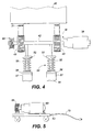
- Other sub-assemblies of the sorting system 10 include a self-tensioning gear motor drive system 36 for providing proper tension in the cog belt conveyors 21 of the cog belt conveyor system 20, as shown in Fig. 6.
- the cog belt conveyor system 20 is comprised of a pair of cog belt conveyors 21 configured in spaced-apart relation for transporting an object such as parcel 40 on the upper surface of the cog belt conveyors 21.
- the cog belt conveyors 21 include a smooth outer conveying surface.
- Cog teeth 22 are disposed along the inner surface of the cog belt conveyors 21 for engaging a cog belt drive mechanism 24.
- the drive mechanism 24 preferably includes a drive sprocket 26 configured for engagement with the cog teeth 22 disposed along the inner surface of the cog belt conveyors 21, as shown in Fig. 2.
- An electric motor (not shown) is preferably functionally attached to the drive sprocket 26.
- the cog belt conveyors 21 are supported at the end opposite the cog belt drive means 24 by an idle sprocket 25.
- a feed conveyor 53 is provided for automatically loading objects, such as parcel 40, onto the cog belt conveyor system 20.
- a centering roller bed 50 is interposed between the feed conveyor 53 and the cog belt conveyor system 20.
- the centering roller bed 50 is comprised of a plurality of rollers 52 configured in a herringbone configuration.
- the roller bed 50 serves to center and properly orient an object such as a parcel 40 onto the parallel cog belt conveyors 21, as shown in Fig. 1.
- a plurality of discharge chutes 45 are provided adjacent to the cog belt conveyors 21 for receiving parcels 40 discharged from the surface of the cog belt conveyors 21, as will be discussed and detailed below. It should be understood, that a variety of discharge destinations may be utilized, such as bins and separate conveyors (not shown).
- FIG. 3 An alternate configuration for the cog belt conveyor system 20 is shown in Fig. 3.
- the cog belt conveyors 21 are supported by a pair of idler rollers 35.
- the cog belt conveyors 21 of this embodiment are disposed about the idler rollers 35 such that the outer conveying surface of the cog belt conveyors 21 include cog teeth for engagement with a self-tensioning gear motor drive system 36.
- the inner surface of the cog belt conveyors 21 are smooth for engagement with the idler rollers 35.
- the self-tensioning gear motor drive system 36 includes a reversible gear motor 38. As shown in Fig. 4, the reversible gear motor 38 is attached to a drive shaft 42 on which is disposed a pair of drive sprockets 43 for engaging and driving the pair of parallel cog belt conveyors 21. As shown in Fig. 3, a pair of snub rollers 44 are utilized to keep the cog belt conveyors 21 in continuous engagement with the drive sprockets 43.
- a tensioning mechanism 54 is provided for maintaining proper tension in the cog belt conveyors 21 of this embodiment of the present invention.
- the tensioning mechanism 54 is comprised of a tension spring 55 which is retained by a spring retaining member 52.
- a spring compression and release member 56 At the lower end of the tension spring 55 is a spring compression and release member 56.
- the spring compression and release member 56 is actuated by hydraulic cylinder 57 which contains hydraulic fluid 58.
- a suitable pneumatic cylinder may be used in place of the hydraulic cylinder 57.
- Tension in the cog belt conveyors 21 may be increased by manually actuating the hydraulic cylinder 57, or operation of the tensioning mechanism 54 may be directed by a programmable logic controller (not shown). It should be understood, that a variety of tension spring mechanisms may be used in place of the tensioning mechanism 54 for manually or automatically maintaining constant tension in the cog belt conveyors 21.
- a portable gear motor 60 is provided for powering the sprockets 40 and cog belt conveyors 21 in the event of a failure of the reversible gear motor 38.
- the portable gear motor 60 is mounted on a wheeled table 63 to allow the portable gear motor 60 to be moved into any desired position.
- an emergency drive sprocket 68 is disposed on the end of the drive shaft 42 opposite the reversible gear motor 38.
- the portable gear motor 60 includes a drive sprocket 69 for engagement with the emergency drive sprocket 68.
- a power cord 72 is included for providing power to the portable gear motor 60.
- the sorting system 10 includes a plurality of ejection mechanisms 80 for ejecting an object, such as a parcel 40, laterally from the upper surface of the cog belt conveyors 21 to an adjacently disposed discharge destination, such as a chute 45, or other desired discharge destination, such as a bin, or alternate conveyor.
- the ejection mechanism 80 shown in Figs. 1 and 6, is disposed medially of the parallel cog belt conveyors 21.
- the ejection mechanism 80 is mounted subjacent to the upper surface of the cog belt conveyors 21.
- the ejection mechanism 80 includes a discharge drum 85 and a discharge drum drive motor 87, as shown in Figs. 6, 7 and 8.
- the discharge drum 85 is an elongate member defining a generally rectangular transaxial cross-section and having upper and lower surfaces 89a and 89b.
- the discharge drum 85 has first and second opposing sides 86a and 86b. which are disposed adjacent to the upper and lower surfaces 89a and 89b.
- the first and second opposing sides 86a and 86b are generally convex shaped and are separated by the longer cross-sectional diameter of the discharge drum 85.
- a plurality of flexible ridges 92 are disposed along the surfaces of the convex opposing sides 86a and 86b of the discharge drum 85.
- the flexible ridges 92 may be made from any suitable polymer material such as polyurethane. As will be discussed below, the flexible ridges 92 assist in ejecting an overlying object, such as the parcel 40 from the conveying surface of the cog belt conveyors 21.
- a discharge drum drive shaft 88 is configured through the central longitudinal axis of the discharge drum 85.
- a discharge drum drive sheave 93 is attached to one end of the discharge drum drive shaft 88, as shown in Fig. 8.
- a reversible discharge drum drive motor 87 includes a drive motor sheave 96 for driving a drive belt 90 to impart rotation to the discharge drum 85.
- the axis of rotation of the discharge drum 85 is defined by the discharge drum shaft 88.
- the axis of rotation of the discharge drum 85 lies along the axial center of the path of travel of the cog belt conveyors 21.
- the axis of rotation of the discharge drum 85 remains fixed beneath the conveying surfaces of the cog belt conveyors 21.
- the ejection mechanism 80 is used to discharge an object such as the parcel 40 from the upper surface of the cog belt conveyors 21, as shown in Fig. 7.
- the configuration of the ejection mechanism 80 represents the rest state of the ejection mechanism 80.
- the upper surface 89a of the discharge drum 85 is in the up position, as shown in Fig. 6.
- the upper surface 89a lies subjacent to the conveying surfaces of the cog belt conveyors 21. Accordingly, an object, such as a parcel 40, may freely travel over the ejection mechanism 80, if desired.
- the discharge drum drive motor 87 is energized when the parcel 40 moves into a position immediately above the ejection mechanism 80. If it is desired that the parcel 40 be discharged to a chute 45 located to the right of the ejection mechanism 80, the discharge drum drive motor is energized so that the discharge drum rotates in a clockwise manner, as shown in Fig. 7. It should be understood, however, that the parcel 40 may be discharged to the chute 45 located to the left of the ejection mechanism 80 by reversing the polarity on the discharge drum drive motor 87 in a manner well known to those skilled in the art.
- energization of the discharge drum drive motor rotates the discharge drum 85 clockwise or counterclockwise, as desired.
- the discharge drum 85 rotates, one of the two convex opposing sides 86a rotates through an arcuate path.
- the arcuate path begins below a plane defined by the upper surface of the cog belt conveyors 21 and rises above that plane through an opening defined by the space between the cog belt conveyors 21 or between the roller arrays, shown in Fig. 9 and discussed below.
- the arcuate path then terminates below the plane defined by the surface of the cog belt conveyors 21.
- one of the convex opposing sides 86a contacts the lower surface of the parcel 40, as shown in Fig. 7, and lifts the parcel 40 up and away from the surface of the cog belt conveyors 21.
- the flexible ridges 92 disposed on the surfaces of the convex opposing sides provide contact surfaces to assist in movement of the parcel 40 by increasing friction between the convex opposing side and the parcel 40.
- the discharge drum 85 As the discharge drum 85 continues to rotate, the parcel 40 is tilted away from the upper surfaces of the cog belt conveyors 21 and onto an idler roller 46 interposed between the cog belt conveyors 21 and the chutes 45, as shown in Fig. 7. Finally, as the discharge drum 85 completes a full 180 degrees of rotation, the parcel 40 is translated onto the chute 45 and off the conveying surfaces of the cog belt conveyors 21 . Accordingly, rotation of the discharge drum 85, as described, lifts, tilts, and translates the parcel 40 from the conveying surfaces of the cog belt conveyors 21, and such rotation returns the discharge drum to a rest position, as shown in Fig. 6.
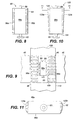
- an alternate embodiment of the present invention provides an ejection mechanism 80 disposed beneath the conveying surface of a roller bed conveyor 100.
- the roller bed conveyor 100 defines a pair of spaced-apart arrays of rollers. It should be understood that the rollers may be powered or non-powered idler rollers.
- the rollers define axes of rotation which are transverse to the axis of rotation of the discharge drum 85.
- the roller bed conveyor 100 and ejection mechanism 80 may be positioned adjacent to desired discharge destinations and interposed between two belt conveyors 105 and 110, or the ejection mechanism and roller bed 100 configuration shown in Fig. 9 may form part of a continuous roller bed conveyor arrangement (not shown).
- a tapered discharge drum 120 is shown in Figs. 10 and 11.
- a transaxial cross-sectional view of the tapered discharge drum 120 shows a generally rectangular shaped discharge drum 120, defining convex opposing sides 123a and 123b separated by the longer diameter of the drum.
- the convex opposing sides 123a and 123b of the tapered discharge drum 120 define flexible ridges 126 and are tapered longitudinally, narrowing toward the end having the drive sheave 96 for engagement with the drum drive motor 87 via a drive belt 90, as shown in Fig. 6.
- the tapered discharge drum also tapers longitudinally narrowing in the direction opposite to the of travel of the cog belt conveyors 21. Accordingly, the second end 125 of the tapered discharge drum 120 is wider than the first end 124.
- Discharge of a parcel 40 using the non-tapered discharge drum 85 tends to rotate the parcel 40 as the parcel 40 is being discharged. Rotation of the parcel is a result of the forward movement of the parcel 40 along the cog belt conveyors 21 in concert with the lateral displacement of the parcel 40 by the discharge drum 85. More specifically, as the tapered discharge drum 85 lifts the parcel 40 off one of the cog belt conveyors 21 , the other cog belt conveyor continues to urge the parcel in a forward direction, resulting in an unbalanced force that causes rotation of the parcel 40.
- the tapered discharge drum 120 may be utilized to counteract rotation of the parcel 40 as it is discharged from the cog belt conveyors 21, as shown in Fig. 7.
- the parcel 40 is discharged from the surface of the cog belt conveyors 21 by the tapered discharge drum, the parcel 40 is contacted first by the wider second end 125 of the tapered discharge drum 120 which urges the parcel 40 in a direction counter to the direction of rotation caused by the cog belt conveyor 21. Accordingly, the parcel 40 is discharged from the conveying surfaces of the cog belt conveyors 21 without undesired rotation.
- the ejection mechanism need not be a drum and that the side of the ejection mechanism that engages the parcels 40 need not be a continuous surface.
- the automated sorting system 10 is operated under the control of a digital controller, which may be a programmable logic controller (PLC) or a general purpose microprocessor which is found in a personal computer.
- a digital controller which may be a programmable logic controller (PLC) or a general purpose microprocessor which is found in a personal computer.
- PLC programmable logic controller
- Methods for programming such controllers to operate a sorting system of the type disclosed herein are conventional and known to those skilled in the art.
- the number of and location of ejection mechanisms 80 and an identification code for each ejection mechanism 80 are input into the controller memory when movement of the sorting system 10 begins.
- Parcels 40 are induced sequentially onto the roller bed 50 from the feed conveyor 53, as shown in Figs. 1 and 2.
- a destination code for each parcel 40 is entered into the controller memory using an optical reader 51, a keypad (not shown), or a voice recognition input device (not shown) before the parcel 40 is directed onto the cog belt conveyor system 20.
- a suitable optical reader system 51 for imaging the destination code from a label affixed to the parcel 40 is shown in U.S.
- Patents 5,291,564; 5,308,960; 5,327,171; and 5,430,282 which are incorporated herein by reference.
- the roller bed 50 with herringbone configuration rollers 52, centers the parcel 40 so that the parcel 40 squarely aligns about the longitudinal axis of the cog belt conveyor system 20 and on the surfaces of the cog belt conveyors 21, as shown in Fig. 1.
- the PLC When the parcel 40 reaches a desired output destination, such as a chute 45 in a position overlying a desired ejection mechanism 80, the PLC energizes the discharge drum drive motor 87 to actuate the ejection mechanism 80. Accordingly, the discharge drum 85 rotates in the direction of the chute 45. As the discharge drum 85 rotates about the discharge drum drive shaft 88, one of the first and second convex shaped opposing sides arcuately translates between the pair of continuous cog belt conveyors 21 and above the upper surface of the continuous cog belt conveyors 21. The discharge drum 85 rotates in the direction of the chute 45, and the parcel 40 is lifted from the surfaces of the cog belt conveyors 21, as shown in Fig. 7.
- the discharge drum 85 continues to rotate in the direction of the chute 45, the parcel 40 is tilted on to the idler roller 46, as shown in Fig. 7. Finally, as the discharge drum completes its rotation, as described in detail above, the parcel 40 is discharged onto the chute 45, as shown in Fig. 7. After the parcel 40 is discharged to the chute 45, the discharge drum 85 stops in a rest position, as shown in Fig. 6, and stands ready to discharge a subsequent parcel 40. If it is desired that package rotation be counteracted as the parcel is discharged to the chute 45, a tapered discharge drum 120 may be utilized instead of the discharge drum 85, as described above.
- ejection mechanism 80 allows the parcel 40 to be discharged from the surfaces of the cog belt conveyors 21 independent of the speed of the parcel 40 moving along the cog belt conveyors 21. Additionally, interaction of the flexible ridges 92 disposed along the surfaces of the convex opposing sides of the discharge drum 85 or the tapered discharge drum 120 reduces noise created by the impact of the discharge drum 85 with the overlying parcel 40.
- failure of an individual ejection mechanism 80, or the cessation of use of an individual ejection mechanism 80 for the maintenance purposes does not create downtime for the cog belt conveyor system 20.
- the PLC may direct parcels to be discharged to alternate discharge destinations and bypass the stopped ejection mechanism 80. Furthermore, the discharge drums may be quickly and easily replaced. Accordingly, downtime of the cog belt conveyor system 20 is reduced.
- the disc can be substantially round in shape, or can include a "flat spot”, and can also either be of substantially unitary construction or multi-segmented.
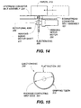
- Fig. 12 is a top plan view of a portion of a conveyor system illustrating an ejection disc 100 located between upstream and downstream conveyor belt assemblies 120, 121, respectively, and rotatably driven about an axis 105.
- Fig. 13 is an "upstream" sectional view taken generally along the conveying axis, showing an ejection disc 100 ejecting a package to the viewer's right.
- the parcel 112 is moved along a generally straight conveyor axis 113, being first positioned atop an upstream conveyor belt assembly 120, and is conveyed towards and onto a second downstream conveyor belt assembly 121, unless it is ejected.
- An ejection disc 100 is rotatably located within a relatively narrow transverse "slot" or "gap" 110 intermediate the two belts of the two assemblies 120, 121 to provide the ejection. It should be understood that the gap is substantially narrow in that it is shorter along the conveying dimension that in its transverse, perpendicular dimension.
- a side chute 112 is positioned at approximately 90 degrees relative to the conveying axis 113, and received ejected packages.
- a parcel 12 is shown in approaching the ejection disc 100. If the ejection disc 100 ejects the parcel 112, the parcel will be urged into the area of a side chute 114. If the ejection disc 100 does not eject the parcel 112 as shown in Fig. 13, the parcel is passed from the upstream conveyor belt assembly 120 to the downstream conveyor belt assembly 121.
- the two conveyor belts within the two conveyor belt assemblies include substantially planar upper conveying surfaces, which lie substantially along the same horizontal plane.
- the disc 100 can be round or may include a truncated section defined in part by a flat spot 102. In either case, the peripheral edge 101 of the ejection disc 100 is brought into contact with the underside of the package as discussed later, such that the parcel is discharge to the viewer's right as viewing Fig. 13.
- the gap 110 can be thought of as having a thickness defined by the closest distance shown between the two conveyor belts, and can be thought to extend above, below, and to intersect the conveying axis.
- Figs. 14-17 illustrate the use of a ejection disc 200 with a flat spot defining a truncated section.
- a "truncated" disc is used which fits within the transverse slot defined by the end of one belt conveyor and the beginning of a second, downstream belt conveyor.
- This disc includes a truncated section which operates much the same way as the "truncated” drum described earlier.
- the truncated disc is rotatably mounted on a fixed axis, and selective rotation causes the disc to engage and eject a package, when rotation is suitably timed.
- FIG. 14 is a side elevational view of a conveyor configuration.
- a package 212 can be moved from an upstream conveyor belt assembly 220 to a downstream conveyor belt assembly 221, unless ejected by a ejection disc 200 as described below.
- the two conveyor belts within the two conveyor belt assemblies 220, 221, include substantially planar upper conveying surfaces, which lie substantially along the same horizontal plane.
- the ejection disc 200 is positioned within and rotates within a transverse gap 210 intermediate the two belts assemblies 220, 221.
- the ejection disc 200 includes a flat section 202.
- the flat section 202 allows passage of the package. Otherwise, the disc 200 is at least partially in the conveyor path.
- Figs. 16 and 17 illustrate what happens when the ejection disc is rotated 180 degrees about its rotational axis 205 from that shown in Figs. 14 and 15.
- the ejection disc 200 is actuated through rotation, its curved portion (having a gripping surface) rises above the conveyor surface, causing the package to be lifted.
- this engagement causes the package to encounter a force substantially 90 degrees in relation to the conveying axis of the package moving from upper conveyor belt assembly 220 to upper conveyor belt assembly 221.
- the ejection disc 200 is rotatably mounted relative to the conveying path of the packages in contacts.
- This rotational axis in the configuration shown in Figs. 14-17, is substantially stationary, horizontal, and parallel to the conveying axis of the packages above, although slight variations may be provided as needed.
- the conveying axis lies substantially along a drive shaft 231 which is rotatably driven by an indexing servo motor 230.
- This indexing servo motor is configured to be selectively activated to rotate the disc 200 in either rotational direction, allowing ejection to be provided to either side of the conveying axis.
- Fig. 15 and 17 show the outer edge of the ejection disc includes a plurality of teeth 203, which may be comprised of rubber.
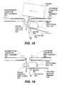
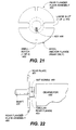
- FIG. 18 illustrates the use of a round ejection disc 300 which is indexed upwardly above the conveying surface within the gap 310 between two conveyors by use of a pivoting action.
- This configuration includes a round ejection disc 300 mounted to a shaft which is rotatably driven by a motor 330.
- the motor 330 which can be continuously running if desired, is mounted to a pivoting support member 333 which is pivotably mounted relative to a stationary conveyor frame member (not shown).
- This pivoting support member 333 is pivotably mounted about a pivoting axis which is substantially horizontal as well as transverse to and below the package conveying axis path.
- a linear actuator 340 is provided which actuates the frame member 333, the motor 330, and the disc 300 from a retracted (non ejecting) position (see Fig. 18) to an extended (ejecting) position (see Fig. 19).
- the actuator 340 (which may be an air or other extendable cylinder) urges the disc 300 upwardly, the rotational axis 305 goes from being substantially horizontal to inclined. Hydraulic, pneumatic, or other suitable actuation means known in the art can be used.
- the narrow, substantially circular, ejection disc 300 fits within the transverse "slot" 310 defined by the end of an upstream belt conveyor assembly 320 and a downstream and the beginning of a second, downstream belt conveyor assembly 321.
- the circular disc 300 is rotatably mounted on a movable rotational axis 305. While in its "neutral” position as shown in Fig. 22, the disc 300 does not contact the packages as they pass from the upstream to the downstream conveyor. However, when actuated, the disc 300, being moved upwardly to its "engaging" position shown in Fig. 21, contacts the package on its circular edge. Rotation of the disc causes the package to be discharged sidewardly.
- the above motor 330 can be reversible to allow for discharge to either side of the conveyor. If desired, the motor can be left continuously running allowing the actuator to determine when ejection occurs.
- the motor 330, as with all the motors described in this application can be selected as known in the art.
- This concept generally relates to the use of a "quick change" feature which allows the narrow discs be quickly removed and replaced with little or no tools and with minimal disturbance to adjacent machinery. This is very important to those operating and maintaining said machinery, in that downtime due to repairs are desired to be at a minimum.
- Figs. 20-28 show a first multi-segment example, with a multi-segmented ejection disc 400.
- Figs. 29-35 show a second multi-segment example, including a multi-segmented ejection disc 500.
- Figs. 36-37 show a third multi-segment example, including a multi-segmented ejection disc 600.
- Figs. 20-28 show a first multi-segmented disc example, including a multi-segmented ejection disc 400 which generally includes a pair of half wheel segments 402, which are captured between a front plate 450 and a rear flanged plate assembly 460 and maintained in place by use of a tension spring 470, to form a substantially circular ejection disc 400, although a wheel with a flat spot is readily contemplated.
- a multi-segmented ejection disc 400 which generally includes a pair of half wheel segments 402, which are captured between a front plate 450 and a rear flanged plate assembly 460 and maintained in place by use of a tension spring 470, to form a substantially circular ejection disc 400, although a wheel with a flat spot is readily contemplated.
- Fig. 20 illustrates the multi-segmented round ejection disc 400 in position within a gap 410 between upstream and downstream conveyor belt assemblies 420, 421, respectively.
- the ejection disc 400 is mounted to a shaft 431 which is rotatably driven by a gear motor 430.
- the gear motor 430 is mounted to a pivotable support member 433 and actuated about pivoting axis by an actuator 440.
- the pivotable support member 433 is pivotably mounted relative to an unshown stationary frame member about a pivoting axis which is substantially horizontal as well as transverse to and below the package conveying axis path.
- the actuator 440 has essentially two positions, an "ejecting position", and a “retracted” position, and is configured to operate such that the multi-segmented ejection disc 400 can be raised generally upwardly and downwardly within the gap 410 much as the disc 300 moved as shown in Figs. 18 and 19.
- the configuration will be assumed to have a “front” and a “back”, although such terms are not to be construed as being limiting.
- the "front” of the ejection disc 400 is the part oriented to the viewer's left as viewing Fig. 20.
- a rear flanged plate assembly 460 which includes a rear plate 461, a rear flange 464, and a set screw 465.
- the rear plate 461 includes two opposing large slots 462, and also includes two small notches 463.
- the large slots 462 are oriented approximately 90 degrees from the opposing smaller notches 463.
- the rear flange 464 is substantially rigidly attached to the rear plate 461, by welding or other means known in the art.
- the set screw 465 allows for attachment of the rear flange 464 to the shaft 431, as known in the art.
- FIG. 23 is a pictorial isolated view of a half wheel member 402, two of which are used for each disc 400.
- Each of the half wheel members 402 includes a corresponding embedded rod 404.
- embedded rod slot 405 or other suitable engaging means At the front end of each embedded rod is defined in embedded rod slot 405 or other suitable engaging means, and at the opposite, rear, end is an embedded rod hook 406 or other suitable engaging means.
- the embedded rod slots 405 are each configured to accept one end of a tension spring 470, and the embedded rod hooks 406 are configured to pass through slots 463 of the rear flange plate 461, and engage the rear side of the rear flange plate 461.
- Each of the half wheel members 402 is configured mostly of molded urethane in one preferred embodiment with the exception of the metal embedded rod 404.
- the rods 404 have a rectangular transverse cross section.
- FIG. 24 is an illustration of a front steel plate 450 of approximately 1/8 inch in thickness.
- This front plate includes two opposing large slots 452, and two opposing small notches 453.
- the opposing large slots 452 and two opposing small notches 453 of the steel front plate 450 are similar in configuration to those provided in the rear plate 461 of the rear flange plate assembly 460.
- a tension spring 470 and a "pipe” 471 are also included.
- a key 466 is used to provide a keyed connection as described later.
- the rear flanged plate assembly 460 is mounted to the shaft 431 of the gear motor 430, by passing the collar-shaped rear flange 464 over the substantially circular outline of the shaft 431.
- a set screw 465 is installed in order to fix the rear flange 464 to the shaft 431 of the gear motor 430.
- a key as known in the art provided a keyed engagement between the rear flanged plate assembly 460 and the shaft 431.
- the two half wheel members 402 are situated as shown in Fig. 25, and held in place by the use of a front plate 450 as shown in Fig. 27.
- the half knob segments 403 of the half wheel members 402 combine to provide substantially elliptically-shaped knobs, shown well in Fig. 26. These knobs are partially contained by the large cut outs of the front plate 450, which serves to capture the half wheel members 402 between the front plate 450 and the rear plate 461 of the rear flange plate assembly 460.
- the embedded rods 404 of the half wheel members are configured such that their hooks 406 are engaged with the "rear" side of the rear flange plate 461, as shown in Figs. 25 and 26.
- the front plate 450 is positioned into place as shown in Fig. 27. As may be understood, the front plate is placed relative to the half wheels and their embedded rods 404, such that the front ends of the embedded rods pass through the small notches 453 of the front plate 450.
- a tension spring 470 is stretched such that its two ends engage respective slots 405 in the front ends of the embedded rods 404, such that the spring ends are engaged with the respective embedded rod slots 405.
- a pipe spacer 471 is placed in engagement with the front plate 450. The spring is then positioned into place, such that the spring is engaged at its ends with the embedded rods, and the medial portion of the spring 470 biases radially against the end of the substantially short pipe spacer 471, which biases inwardly onto the front plate 450.
- a curved portion is provided in the pipe spacer to accommodate the round nature of the spring, and to discourage removal of the pipe spacer.
- the pipe spacer 47 in one example, fits about the end of the shaft 431 of the gear motor 430. This engagement, combined with the biasing of the spring, tends to maintain the pipe spacer in place.
- a key 466 as known in the art to provide suitable engagement between the rear flange 464 and the shaft 431, to discourage rotation therebetween.
- FIG. 20-28 Operation of the configuration shown in Figs. 20-28 is similar to that discussed in reference to Figs. 18 and 19.
- a motor 430 is used which drives the ejection disc 400, such that when the motor 430 and rotating disc 400 is pivoted upwardly by an actuator 440, the ejection disc engages and discharges packages passing gap 410.
- this configuration includes the use of an pivoting configuration, if a flat spot is provided in one or both of the half wheels 402, as may be understood, no pivoting is required; the motion will be as described earlier with respect to Figs. 14-17.
- a user will disengage the spring 470 from its location, remove the pipe spacer 471, remove the front plate 450, and remove and replace as needed either or both of the half wheels 402.
- the front plate 450 is then positioned as shown in Fig. 27 and 20, and the pipe spacer 471 and spring 470 are situated into place as shown in Figs. 20, 27, and 28.
- multi-segmented ejection disc 400 is shown as having a circular gripping perimeter edge, a truncated portion could also be provided by providing such a truncation in at least one of the half wheel segments 402.
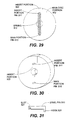
- Figs. 29-35 show a second multi-segment disc 500 , including a main disc portion 502, an insert portion 503, and a spring 512.
- Figs. 29-35 includes a multi-segmented urethane wheel.
- the wheel portion which contacts the package takes the form of two urethane segments, a main disc portion 502 and an insert portion 503.
- the main disc portion 502 includes a large slot therein, and the smaller insert portion is configured to slide within the slot of the main disc portion.
- this insert can include a beveled configuration, which tends to provide engagement between it and the main wheel portion.
- These urethane members 502, 503, are drawn together by the use of a tension spring 512, which has each of its ends engaging one of the headed portions of embedded steel pins.
- the main disc portion 502 includes an embedded pin 510.
- the embedded pin includes a rear hook 520, and includes a front "headed" portion which defines an annular slot 521.
- the main disc portion 502 also includes an insert-receiving slot which at its end includes a substantially arcuate portion having a keyway slot therein.
- the keyway slot is configured to accept a key as described elsewhere.
- the insert portion 503 includes an insert portion pin 511 similar in configuration to pin 510 of the main portion 502.
- the insert portion 503 includes an arcuate end, which is configured to conform substantially to a peripheral portion of a shaft as described elsewhere.
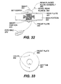
- the rear flanged plate assembly 560 also includes a rear plate 561, a rear flange 564 rigidly attached thereto, and is keyed as known in the art to engage the shaft.
- the front plate 550 is configured to include a key tab 551 to engage a keyway in the drive shaft 531, and includes a pair of through holes 552 to allow passage of the through pins 510, 511.
- a pipe ring 570 is also used as described below.
- both portions 502, 503 is provided with gripping teeth or another suitable gripping surface such as known in the art.
- the rear flanged plate assembly 560 fits onto a shaft 531 of a motor 530.
- the two urethane portions 502, 503, are configured to fit together in their configuration shown in Fig. 32, such that the front plate and the rear plate 561 of the rear plate assembly 560 tend to capture the urethane portions 502, 503, along the length of the shaft 531 of the motor 530.
- the urethane portions 502, 503, are drawn together by the use of a spring 512, which has each of its ends engaging one of the headed portions of the embedded steel pins and captures the pipe ring 570 as shown.
- a keyway is provided to allow keyed engagement between the shaft 531 of the gear motor 530 and the front plate 550, the main urethane wheel member 502, and the rear flange plate assembly 560.
- the spring 512 is first removed, followed by removal of the front plate 550.
- the urethane portions 502, 503, can then be separated by sliding the smaller member 503, out of the main slot of the larger member 502. Replacement of either or both of the urethane members can then be effected.
- the front plate 550 is then replaced, followed by the spring 512.
- a pipe ring 570 as shown in Fig. 32, can be used to fit underneath the spring 512 as shown in Fig. 34.
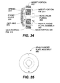
- Figs. 36 and 37 illustrate top plan and side elevational views, respectively of third multi-segmented ejection disc 600 including a main disc portion 602 and an insert portion 603 slidably insertable into the main portion in a manner similar to that described previously, with respect to, for example, Fig. 30.
- a tension spring 612 is used which engages at its ends to two respective pins each of which are installed in the main disc portion on opposing sides of the main portion's insert-receiving slot.
- the medial portion of the spring 612 is stretched around a pin member extending through the insert portion 603 and having upwardly (as shown in the drawings) directed hooks which are biased downwardly (as shown in the drawings), such that the spring force tends to cause the plastic insert to remain seated within its position in the main wheel portion.
- This configuration may be used with a separate means (not shown) to attach the combination of the two elements 602, 603 to a motor shaft 620, or may be modified to operate in conjunction with other mounting elements such as a flanged rear disc assembly and front disc assembly, motor, etc., to be supported and driven thereby in manners similar to those previously discussed.
- the multi-segmented disc 600 includes a "flat spot", although as shown elsewhere in this application such a multi-segment disc could not have a flat section.
- the thickness of the multi-segmented disc 600 as shown in Fig. 36, as well as the other discs may be within the range of 1/2 inch to 3 inches, and can be approximately 12 inches in peripheral diameter although other configurations are contemplated.
- the peripheral edge of the disc 600 intended to engage packages may be provided with engaging teeth or other suitable frictional engaging means known in the art.
- the invention provides an improved conveying and discharge apparatus which provides numerous improvements over the previously-described prior art, not the least of which includes a simple yet effective discharge device which can be easily replaced with little downtime.
Landscapes
- Engineering & Computer Science (AREA)
- Mechanical Engineering (AREA)
- Discharge Of Articles From Conveyors (AREA)
- Spray Control Apparatus (AREA)
- Sorting Of Articles (AREA)
- Branching, Merging, And Special Transfer Between Conveyors (AREA)
- Coating Apparatus (AREA)
- Manufacturing And Processing Devices For Dough (AREA)
- Threshing Machine Elements (AREA)
- Structure Of Belt Conveyors (AREA)
- De-Stacking Of Articles (AREA)
- Vending Machines For Individual Products (AREA)
Claims (27)
- Mécanisme comprenant un organe d'éjection pour éjecter un objet d'une surface support, le perfectionnement comprenant :un organe d'éjection (85,120) de forme allongée et qui est monté de manière à tourner autour d'un axe longitudinal fixe sous-jacent à ladite surface support, caractérisé en ce que ledit organe d'éjection comporte un premier et un second côtés opposés (86a, 86b) allongés, ladite surface support définit une ouverture pour recevoir l'un desdits premier et second côtés opposés allongés ; etdes moyens (87) pour faire tourner ledit organe d'éjection autour dudit axe de telle façon que l'un desdits premier et second côtés opposés allongés tourne à travers ladite ouverture et au-dessus d'un plan défini par ladite surface support de façon à éjecter ledit objet de ladite surface support.
- Mécanisme d'éjection selon la revendication 1, dans lequel ladite rotation de l'un desdits premier et second côtés opposés allongés définit un trajet courbe, ledit trajet courbe commençant en dessous dudit plan défini par ladite surface support, et ledit trajet courbe se terminant en dessous dudit plan défini par ladite surface support.
- Mécanisme d'éjection selon la revendication 1 ou la revendication 2, dans lequel l'un dit desdits premier et second côtés allongés tourne à travers ladite ouverture et au-dessus dudit plan défini par ladite surface support, l'un dit desdits premier et second côtés allongés vient engager une surface inférieure dudit objet, ledit objet étant soulevé de ladite surface support, ledit objet étant basculé en dehors de ladite surface support, et ledit objet étant déchargé vers un emplacement de décharge désigné.
- Mécanisme d'éjection selon l'une quelconque des revendications précédentes, dans lequel ledit premier et second côtés opposés allongés sont généralement de forme convexe.
- Mécanisme d'éjection selon la revendication 4, dans lequel ledit premier et second côtés allongés généralement de forme convexe définissent une pluralité d'arêtes souples.
- Mécanisme d'éjection selon la revendication 5, dans lequel ledit organe d'éjection a la forme d'un tambour asymétrique allongé monté sur un axe horizontal en dessous de ladite surface support.
- Mécanisme d'éjection selon la revendication 6, dans lequel le tambour définit une section transversale trans-axiale généralement rectangulaire comportant des surfaces supérieure et inférieure et un premier et un second côtés opposés, lesdits premier et second côtés opposés étant adjacents auxdites surfaces supérieure et inférieure.
- Mécanisme d'éjection selon la revendication 7, dans lequel ledit tambour comprend en outre une première et une seconde extrémités, lesdits premier et second côtés opposés étant interposés entre ladite première et seconde extrémités, et dans lequel lesdits premier et second côtés opposés se rétrécissent à partir de ladite seconde extrémité vers ladite première extrémité de telle façon que ledit tambour de décharge est plus large au niveau de ladite seconde extrémité qu'au niveau de ladite première extrémité.
- Mécanisme d'éjection selon la revendication 8, dans lequel lesdits premier et second côtés vont en se rétrécissant depuis ladite seconde extrémité vers ladite première extrémité dans une direction opposée à la direction de déplacement de ladite paire de convoyeurs continus.
- Mécanisme d'éjection selon la revendication 9, dans lequel chacun desdits premier et second côtés opposés définit des arêtes souples.
- Mécanisme d'éjection selon la revendication 5,
dans lequel ledit organe d'éjection comporte une première est une secondé extrémités allongées, lesdits premier et second côtés allongés étant interposés entre lesdites première et seconde extrémités ; et
dans lequel chacun desdits premier et second côtés allongés va en se rétrécissant depuis ladite seconde extrémité vers ladite première extrémité, de telle sorte que la largeur dudit organe d'éjection est supérieure au niveau de ladite seconde extrémité qu'au niveau de ladite première extrémité. - Mécanisme d'éjection selon l'une quelconque des revendications précédentes, dans lequel ladite surface support comprend en outre :une paire de convoyeurs continus (21) pour transporter ledit objet, ladite paire de convoyeurs continus étant disposés en parallèle, en étant écartés l'un de l'autre ; etledit mécanisme d'éjection étant disposé médialement par rapport à ladite paire de convoyeurs continus.
- Mécanisme d'éjection selon la revendication 12, dans lequel ladite ouverture définie par ladite surface support comprend un espace interposé entre ladite paire de convoyeurs continus.
- Mécanisme d'éjection selon la revendication 12 ou la revendication 13, comprenant en outre une pluralité de destinations de décharge disposées de manière adjacente à l'un desdits convoyeurs sur l'un ou l'autre de ses côtés.
- Mécanisme d'éjection selon l'une quelconque des revendications 12 à 14, comprenant en outre un mécanisme pour entraíner ladite paire de convoyeurs continus, ledit mécanisme comprenant :des moyens d'entraínement (87) configurés de manière à venir porter contre chacun de ladite paire de convoyeurs continus, lesdits moyens d'entraínement appliquant une force de rotation à ladite paire de convoyeurs continus ;une paire de rouleaux de renvoi (44) pour maintenir l'engagement desdits moyens d'entraínement avec ladite paire de convoyeurs continus ; etun mécanisme de mise sous tension (54) pour maintenir la tension désirée dans ladite paire de convoyeurs continus.
- Mécanisme d'éjection selon la revendication 15, dans lequel ledit mécanisme de mise sous tension comprend :un ressort (55) pour appliquer lesdits moyens d'entraínement en engagement avec ladite paire de convoyeurs continus.
- Mécanisme d'éjection selon la revendication 16, dans lequel ledit mécanisme de mise sous tension comprend en outre :un organe (52) de retenue du ressort interposé entre ledit ressort et lesdits moyens d'entraínement ; etun moyen (57) pour comprimer et détendre ledit ressort contre ledit organe de retenue du ressort.
- Mécanisme d'éjection selon la revendication 17, dans lequel ledit moyen pour comprimer et détendre ledit ressort comprend un vérin hydraulique.
- Mécanisme d'éjection selon l'une quelconque des revendications 15 à 18, dans lequel lesdits moyens d'entraínement comprennent un moteur à engrenage (38) configuré de manière à venir porter contre une surface dentée de chacun de ladite paire de convoyeurs continus.
- Mécanisme d'éjection selon l'une quelconque des revendications 1 à 11, dans lequel ladite surface support comprend en outre :un convoyeur à banc de rouleaux pour transporter ledit objet, ledit convoyeur à banc de rouleaux définissant une paire de rangées espacées de rouleaux, lesdits rouleaux définissant des axes de rotation, lesdits axes de rotation étant dirigés transversalement par rapport audit axe de rotation dudit organe d'éjection, etledit mécanisme d'éjection étant disposé médialement par rapport à ladite paire des rangées espacées de rouleaux.
- Mécanisme d'éjection selon la revendication 20, dans lequel ladite ouverture définie par ladite surface support comprend un espace interposé entre ladite paire des rangées espacées de rouleaux.
- Mécanisme d'éjection selon l'une quelconque des revendications précédentes, dans lequel les moyens pour faire tourner ledit organe d'éjection comprennent un moteur électrique.
- Procédé pour éjecter un objet d'une surface support en utilisant un organe d'éjection rotatif (85,12), selon l'une quelconque des revendications précédentes, le perfectionnement audit procédé comprenant les étapes consistant à :prévoir l'organe d'éjection avec un premier côté allongé ;faire tourner l'organe d'éjection autour d'un axe longitudinal fixe en dessous de ladite surface support ;faire tourner le premier côté allongé dudit organe d'éjection à travers une ouverture définie dans ladite surface support ;mettre en contact ledit objet avec ledit premier côté allongé dudit organe d'éjection ; etdécharger ledit objet de ladite surface support.
- Procédé selon la revendication 23, dans lequel ladite étape consistant à décharger ledit objet comprend l'étape consistant à :soulever ledit objet à partir de ladite surface support ;faire basculer ledit objet en dehors de ladite surface support ; etentraíner en translation ledit objet latéralement en dehors de ladite surface support vers une destination de décharge désirée.
- Procédé selon la revendication 23 ou la revendication 24, comprenant en outre l'étape consistant à :convoyer ledit objet le long de ladite surface support jusqu'à une destination de décharge désirée.
- Procédé selon la revendication 25, comprenant en outre l'étape consistant à :contrecarrer la rotation dudit objet lors de l'étape de décharge dudit objet à partir de ladite surface support en utilisant un organe d'éjection présentant la forme d'un tambour de décharge allongé allant en se rétrécissant.
- Procédé selon l'une quelconque des revendications 23 à 26, dans lequel ladite surface support comprend une paire de convoyeurs continus.
Applications Claiming Priority (3)
| Application Number | Priority Date | Filing Date | Title |
|---|---|---|---|
| US841201 | 1997-04-29 | ||
| US08/841,201 US6076653A (en) | 1997-04-29 | 1997-04-29 | High speed drum sorting conveyor system |
| PCT/US1998/008597 WO1998049080A2 (fr) | 1997-04-29 | 1998-04-29 | Disque pour bande transporteuse a decharge laterale comportant des caracteristiques de changement rapide |
Publications (2)
| Publication Number | Publication Date |
|---|---|
| EP1015362A2 EP1015362A2 (fr) | 2000-07-05 |
| EP1015362B1 true EP1015362B1 (fr) | 2002-08-28 |
Family
ID=25284285
Family Applications (1)
| Application Number | Title | Priority Date | Filing Date |
|---|---|---|---|
| EP98919973A Expired - Lifetime EP1015362B1 (fr) | 1997-04-29 | 1998-04-29 | Mecanisme d'ejection pour transporteuse |
Country Status (9)
| Country | Link |
|---|---|
| US (1) | US6076653A (fr) |
| EP (1) | EP1015362B1 (fr) |
| JP (1) | JP3333215B2 (fr) |
| AT (1) | ATE222878T1 (fr) |
| CA (1) | CA2283844C (fr) |
| DE (1) | DE69807505T2 (fr) |
| DK (1) | DK1015362T3 (fr) |
| ES (1) | ES2182300T3 (fr) |
| WO (1) | WO1998049080A2 (fr) |
Families Citing this family (32)
| Publication number | Priority date | Publication date | Assignee | Title |
|---|---|---|---|---|
| US6401936B1 (en) * | 1999-04-30 | 2002-06-11 | Siemens Electrocom, L.P. | Divert apparatus for conveyor system |
| US6359247B1 (en) * | 1999-07-06 | 2002-03-19 | Quantum Conveyor Systems, Llc | Multi-fire and variable fire diverter conveyor system and method |
| US6264042B1 (en) | 1999-11-15 | 2001-07-24 | United Parcel Service Of America, Inc. | Bilateral sorter |
| US6276508B1 (en) | 1999-12-21 | 2001-08-21 | United Parcel Service Of America, Inc. | Chute having sortation features |
| US6758323B2 (en) * | 2002-05-30 | 2004-07-06 | The Laitram Corporation | Singulating conveyor |
| US7073651B2 (en) * | 2003-07-30 | 2006-07-11 | Laitram, L.L.C. | Modular mat gravity-advance roller conveyor |
| US7637366B2 (en) * | 2004-06-04 | 2009-12-29 | Shuttleworth, Inc. | High speed diverter |
| US20070012545A1 (en) * | 2005-07-13 | 2007-01-18 | Lockheed Martin Corporation | Separator and method of use |
| DE102006035050A1 (de) * | 2006-07-28 | 2008-01-31 | Siemens Ag | Verteileinrichtung für Stückgut |
| US20100300498A1 (en) * | 2009-06-01 | 2010-12-02 | Wojciechowski Iii Donald Anthony | Easy change tube cleaning system |
| EP2360100A1 (fr) * | 2010-02-18 | 2011-08-24 | Helmut Spikker | Procédé de fabrication prêt à l'envoi d'articles cosmétiques individuels et dispositif |
| EP2481540B1 (fr) * | 2011-01-28 | 2017-11-01 | Schelling Anlagenbau GmbH | Dispositif de sciage d'au moins deux pièces usinées sous forme de plaques ou de piles de plaques |
| DE102011011642A1 (de) * | 2011-02-18 | 2012-08-23 | Iwk Verpackungstechnik Gmbh | Verpackungsmaschine |
| US9051122B2 (en) | 2012-11-30 | 2015-06-09 | Raymond Edward Poehlein | Idler roller conveyor system |
| US10625304B2 (en) | 2017-04-26 | 2020-04-21 | UHV Technologies, Inc. | Recycling coins from scrap |
| US11964304B2 (en) | 2015-07-16 | 2024-04-23 | Sortera Technologies, Inc. | Sorting between metal alloys |
| US10207296B2 (en) | 2015-07-16 | 2019-02-19 | UHV Technologies, Inc. | Material sorting system |
| US11969764B2 (en) | 2016-07-18 | 2024-04-30 | Sortera Technologies, Inc. | Sorting of plastics |
| US10710119B2 (en) | 2016-07-18 | 2020-07-14 | UHV Technologies, Inc. | Material sorting using a vision system |
| US10722922B2 (en) | 2015-07-16 | 2020-07-28 | UHV Technologies, Inc. | Sorting cast and wrought aluminum |
| US12017255B2 (en) | 2015-07-16 | 2024-06-25 | Sortera Technologies, Inc. | Sorting based on chemical composition |
| US11278937B2 (en) | 2015-07-16 | 2022-03-22 | Sortera Alloys, Inc. | Multiple stage sorting |
| WO2017024035A1 (fr) | 2015-08-03 | 2017-02-09 | UHV Technologies, Inc. | Analyse de métaux pendant la fabrication de produits pharmaceutiques |
| CN105436487A (zh) * | 2015-11-29 | 2016-03-30 | 无锡市鑫茂锻造有限公司 | 铸造生产线的承托式计数输送装置 |
| US10668506B2 (en) * | 2018-04-24 | 2020-06-02 | Beumer Group Gmbh & Co. Kg. | Sorting conveyor with article removal device |
| CN110525912A (zh) * | 2019-10-11 | 2019-12-03 | 安徽九鲤智能设备有限公司 | 一种直线窄带分拣机小车 |
| CN111532719A (zh) * | 2020-05-04 | 2020-08-14 | 三门杉飘医疗器械有限公司 | 一种医疗检测床床板架输送移动机构 |
| CN112305010B (zh) * | 2020-09-10 | 2024-02-13 | 浙江越华能源检测有限公司 | 一种自动可持续测试的灰熔融性测试仪 |
| CN114013933A (zh) * | 2021-11-24 | 2022-02-08 | 赛那德科技有限公司 | 一种自动输送分拣装置 |
| CN114275517B (zh) * | 2022-02-22 | 2024-06-04 | 苏州菲力特智能科技有限公司 | 一种棘轮送料换型机构 |
| CN114768605A (zh) * | 2022-05-27 | 2022-07-22 | 安徽金源药业有限公司 | 一种基于工业互联网的自动定量投料制药设备 |
| CN117533729B (zh) * | 2023-12-18 | 2024-04-26 | 宁波永耀电力投资集团有限公司 | 液压输送机 |
Family Cites Families (53)
| Publication number | Priority date | Publication date | Assignee | Title |
|---|---|---|---|---|
| US982920A (en) * | 1909-09-20 | 1911-01-31 | William F Laudenschlager | Carrier system. |
| US1114621A (en) * | 1914-03-25 | 1914-10-20 | Harry A Lewis | Roller-table for rolling-mills. |
| US1462511A (en) * | 1922-08-18 | 1923-07-24 | Charles H Lister | Reciprocating conveyer system |
| US1549499A (en) * | 1923-08-28 | 1925-08-11 | Parker Donald | Elevating means for sorting tables |
| US1737829A (en) * | 1924-01-17 | 1929-12-03 | United Shoe Machinery Corp | Conveying system |
| US1959157A (en) * | 1931-03-13 | 1934-05-15 | Standard Conveyor Co | Live roller conveyer |
| US2062604A (en) * | 1935-05-31 | 1936-12-01 | Fmc Corp | Box switching unit |
| US2622720A (en) * | 1950-09-07 | 1952-12-23 | United States Steel Corp | Roller conveyer |
| US3026988A (en) * | 1959-04-06 | 1962-03-27 | Mathews Conveyer Co | Article transfer device |
| US3138238A (en) * | 1962-04-16 | 1964-06-23 | Rapids Standard Co Inc | Powered diverter |
| US3189161A (en) * | 1962-12-21 | 1965-06-15 | Rapids Standard Co Inc | Powered roller curve |
| US3231068A (en) * | 1963-01-07 | 1966-01-25 | Prospect Mfg Co Inc | Article delivery conveyer |
| US3253692A (en) * | 1963-04-11 | 1966-05-31 | Ota Isamu | Automatic cart-lifting apparatus with stationary stairs |
| DE1186402B (de) * | 1963-12-24 | 1965-01-28 | Telefunken Patent | Foerdereinrichtung fuer eine Belegbearbeitungsmaschine, insbesondere -sortiermaschine |
| US3286811A (en) * | 1964-12-31 | 1966-11-22 | Joseph E Mcwilliams | Selective delivery tilting slat conveyor for mail bag handling systems |
| US3348678A (en) * | 1966-01-10 | 1967-10-24 | Stanley L Flowers | Automatic weight grading apparatus |
| US3369646A (en) * | 1966-04-11 | 1968-02-20 | Musser Inc | Conveyor apparatus |
| US3552541A (en) * | 1969-01-29 | 1971-01-05 | Owens Illinois Inc | Article handling apparatus |
| US3642113A (en) * | 1970-08-17 | 1972-02-15 | Conveyor Systems | Apparatus for discharging articles from a moving conveyor |
| US3724643A (en) * | 1971-06-28 | 1973-04-03 | Diebold Inc | Tapered roll conveyor curve construction |
| SU470159A1 (ru) * | 1971-12-22 | 1976-08-25 | Издательство "Известия" Советов Депутатов Трудящихся Ссср | Устройство дл перемещени штучных грузов в двух взаимно перпендикул рных направлени х |
| US3782527A (en) * | 1973-01-17 | 1974-01-01 | Rex Chainbelt Inc | Clipped-disc device for right-angle transfer |
| SU466745A1 (ru) * | 1973-12-21 | 1979-10-05 | Издательство "Известия" | Механизм перегрузки штучных грузов во взаимно перпендикул рных направлени х" |
| FR2256092B3 (fr) * | 1973-12-27 | 1977-11-25 | Handling Systems Internal Ltd | |
| US3880751A (en) * | 1973-12-27 | 1975-04-29 | Speaker Motion Systems | Conveyors with lateral discharge apparatus |
| US3918572A (en) * | 1974-05-09 | 1975-11-11 | Speaker Motion Systems | Lateral discharge chute and gate apparatus |
| US4143755A (en) * | 1975-09-29 | 1979-03-13 | Pullman Incorporated | Roller conveyor with alignment device |
| DE2547899A1 (de) * | 1975-10-25 | 1977-04-28 | Enzinger Union Werke Ag | Vorrichtung zum aufloesen oder zusammenstellen insbesondere von flaschenkastenschichten oder -bloecken |
| DE2748434A1 (de) * | 1977-10-28 | 1979-05-03 | Sandvik Conveyor Gmbh | Foerder- und verteilanlage fuer stueckgut |
| DE2818425A1 (de) * | 1978-04-27 | 1979-11-08 | Zdarske Strojirny A Slevarny | Scheibenumfuehrer fuer bleche und andere gueter mit ebener bodenflaeche |
| IT1122898B (it) * | 1979-08-30 | 1986-04-30 | Francesco Canziani | Apparecchiatura di selezione e smistamento per oggetti |
| US4295559A (en) * | 1980-01-31 | 1981-10-20 | Acco Industries Inc. | Conveyor system with diverter |
| US4583637A (en) * | 1982-09-30 | 1986-04-22 | Roe Incorporated | Conveying apparatus |
| US4633996A (en) * | 1983-06-01 | 1987-01-06 | Timalara Pty. Limited | Belt-conveyor frame |
| US4509636A (en) * | 1983-07-18 | 1985-04-09 | Godbois Arthur G | Diverting roller system |
| US4598815A (en) * | 1984-07-23 | 1986-07-08 | Conveyor Corporation Of America, Inc. | Powered roller diverter |
| US4696386A (en) * | 1985-06-14 | 1987-09-29 | Lem Hans J | Conveyor system diverter turn assembly |
| SU1316954A1 (ru) * | 1985-12-29 | 1987-06-15 | Хабаровский политехнический институт | Продольный конвейер |
| JPH0829814B2 (ja) * | 1986-06-13 | 1996-03-27 | ソニー株式会社 | ロ−ラコンベヤ |
| US4798275A (en) * | 1986-06-30 | 1989-01-17 | Versa Corporation | Line-shaft conveyor diverter |
| NL8700901A (nl) * | 1987-04-16 | 1988-11-16 | Rapistan Van Der Lande Bv | Transporteur. |
| SU1514708A1 (ru) * | 1987-12-08 | 1989-10-15 | Khabarovsk Polt Inst | Пpoдoльhый kohbeйep |
| US5027939A (en) * | 1990-01-24 | 1991-07-02 | Alvey Inc. | Sorting conveyor system |
| US5127510A (en) * | 1990-10-31 | 1992-07-07 | Rapistan Demag Corporation | Modular diverter shoe and slat construction |
| US5107982A (en) * | 1991-01-25 | 1992-04-28 | Shuttleworth, Inc. | Conveyor apparatus |
| WO1993007972A1 (fr) * | 1991-10-15 | 1993-04-29 | Colour Vision Systems Pty. Ltd. | Systeme de convoyage pour produits alimentaires |
| CH685491A5 (de) * | 1992-07-30 | 1995-07-31 | Daverio Ag | Wagen eines Förderers für Stückgüter. |
| US5388681A (en) * | 1992-10-19 | 1995-02-14 | United Parcel Service Of America, Inc. | Inflatable conveyor belt |
| US5421446A (en) * | 1993-03-12 | 1995-06-06 | United Parcel Service Of America, Inc. | Article diverter apparatus for use in conveyor systems |
| US5415273A (en) * | 1993-11-12 | 1995-05-16 | Peterson; Myron A. | Arcuate path chain belt harvester |
| US5433311A (en) * | 1993-11-17 | 1995-07-18 | United Parcel Service Of America, Inc. | Dual level tilting tray package sorting apparatus |
| US5402996A (en) * | 1994-02-16 | 1995-04-04 | Long; John A. | Apparatus and method for feeding cards from selected card stacks using a continuously rotating drive |
| CA2137894C (fr) * | 1994-12-12 | 1998-01-20 | Shuji Yoshino | Transporteur mecanique a rouleaux pour faibles charges |
-
1997
- 1997-04-29 US US08/841,201 patent/US6076653A/en not_active Expired - Lifetime
-
1998
- 1998-04-29 DK DK98919973T patent/DK1015362T3/da active
- 1998-04-29 AT AT98919973T patent/ATE222878T1/de not_active IP Right Cessation
- 1998-04-29 CA CA002283844A patent/CA2283844C/fr not_active Expired - Fee Related
- 1998-04-29 DE DE69807505T patent/DE69807505T2/de not_active Expired - Lifetime
- 1998-04-29 EP EP98919973A patent/EP1015362B1/fr not_active Expired - Lifetime
- 1998-04-29 ES ES98919973T patent/ES2182300T3/es not_active Expired - Lifetime
- 1998-04-29 WO PCT/US1998/008597 patent/WO1998049080A2/fr active IP Right Grant
- 1998-04-29 JP JP54731598A patent/JP3333215B2/ja not_active Expired - Fee Related
Also Published As
| Publication number | Publication date |
|---|---|
| US6076653A (en) | 2000-06-20 |
| ATE222878T1 (de) | 2002-09-15 |
| CA2283844A1 (fr) | 1998-11-05 |
| JP2000514028A (ja) | 2000-10-24 |
| DK1015362T3 (da) | 2002-12-30 |
| DE69807505T2 (de) | 2003-04-24 |
| EP1015362A2 (fr) | 2000-07-05 |
| JP3333215B2 (ja) | 2002-10-15 |
| CA2283844C (fr) | 2004-01-27 |
| ES2182300T3 (es) | 2003-03-01 |
| DE69807505D1 (de) | 2002-10-02 |
| WO1998049080A2 (fr) | 1998-11-05 |
| WO1998049080A3 (fr) | 1999-02-18 |
Similar Documents
| Publication | Publication Date | Title |
|---|---|---|
| EP1015362B1 (fr) | Mecanisme d'ejection pour transporteuse | |
| JP4035530B2 (ja) | 仕分け機および仕分け方法 | |
| JP3326183B2 (ja) | 自動横方向並進コンベヤ | |
| US5117961A (en) | Conveying apparatus and article diverter | |
| EP0799778B1 (fr) | Appareil de triage de colis à plateaux basculants | |
| JP3138483B2 (ja) | 高速傾斜ベルト仕分け機 | |
| EP0673861B1 (fr) | Installation de transport pour déviation et convergence | |
| EP0869087B1 (fr) | Appareil de tri avec des plateaux basculants | |
| EP1962717B1 (fr) | Echangeur de transporteur | |
| US10843876B2 (en) | Hybrid diverter with multi-action transfer bar and method of using same | |
| US4081071A (en) | Conveyor systems | |
| CA2278283C (fr) | Plateau detachable de manutention de materiel dote d'un mecanisme automatique d'ejection de paquets | |
| EP0477104A2 (fr) | Unité de tri modulaire pour systèmes de convoyage | |
| US5950798A (en) | Air distribution systems for shoe sorter | |
| US5967290A (en) | High speed bobbin-type sorter for parcels | |
| CA2124150A1 (fr) | Poste de transfert de bois d'oeuvre | |
| US6182813B1 (en) | Side conveyor disc including quick-change features | |
| EP1240093B1 (fr) | Bande transporteuse a plateau basculant comportant un seul soufflet a double action | |
| US4946022A (en) | Article sorting switch | |
| CA2441618C (fr) | Disque pour bande transporteuse a decharge laterale comportant des caracteristiques de changement rapide | |
| US20090014282A1 (en) | Apparatus for spacing boards | |
| WO1999046189A1 (fr) | Transporteur a palettes | |
| GB2197278A (en) | Method and apparatus for conveying tipping and diverting articles |
Legal Events
| Date | Code | Title | Description |
|---|---|---|---|
| PUAI | Public reference made under article 153(3) epc to a published international application that has entered the european phase |
Free format text: ORIGINAL CODE: 0009012 |
|
| 17P | Request for examination filed |
Effective date: 19991108 |
|
| AK | Designated contracting states |
Kind code of ref document: A2 Designated state(s): AT BE CH CY DE DK ES FI FR GB GR IE IT LI LU MC NL PT SE |
|
| 17Q | First examination report despatched |
Effective date: 20000831 |
|
| RTI1 | Title (correction) |
Free format text: EJECTION MECHANISM FOR CONVEYOR |
|
| GRAG | Despatch of communication of intention to grant |
Free format text: ORIGINAL CODE: EPIDOS AGRA |
|
| RTI1 | Title (correction) |
Free format text: EJECTION MECHANISM FOR CONVEYOR |
|
| GRAG | Despatch of communication of intention to grant |
Free format text: ORIGINAL CODE: EPIDOS AGRA |
|
| GRAH | Despatch of communication of intention to grant a patent |
Free format text: ORIGINAL CODE: EPIDOS IGRA |
|
| GRAH | Despatch of communication of intention to grant a patent |
Free format text: ORIGINAL CODE: EPIDOS IGRA |
|
| GRAA | (expected) grant |
Free format text: ORIGINAL CODE: 0009210 |
|
| AK | Designated contracting states |
Kind code of ref document: B1 Designated state(s): AT BE CH CY DE DK ES FI FR GB GR IE IT LI LU MC NL PT SE |
|
| PG25 | Lapsed in a contracting state [announced via postgrant information from national office to epo] |
Ref country code: GR Free format text: LAPSE BECAUSE OF FAILURE TO SUBMIT A TRANSLATION OF THE DESCRIPTION OR TO PAY THE FEE WITHIN THE PRESCRIBED TIME-LIMIT Effective date: 20020828 Ref country code: FI Free format text: LAPSE BECAUSE OF FAILURE TO SUBMIT A TRANSLATION OF THE DESCRIPTION OR TO PAY THE FEE WITHIN THE PRESCRIBED TIME-LIMIT Effective date: 20020828 Ref country code: AT Free format text: LAPSE BECAUSE OF FAILURE TO SUBMIT A TRANSLATION OF THE DESCRIPTION OR TO PAY THE FEE WITHIN THE PRESCRIBED TIME-LIMIT Effective date: 20020828 |
|
| REF | Corresponds to: |
Ref document number: 222878 Country of ref document: AT Date of ref document: 20020915 Kind code of ref document: T |
|
| REG | Reference to a national code |
Ref country code: GB Ref legal event code: FG4D |
|
| REG | Reference to a national code |
Ref country code: CH Ref legal event code: EP |
|
| REF | Corresponds to: |
Ref document number: 69807505 Country of ref document: DE Date of ref document: 20021002 |
|
| REG | Reference to a national code |
Ref country code: IE Ref legal event code: FG4D |
|
| REG | Reference to a national code |
Ref country code: CH Ref legal event code: NV Representative=s name: KELLER & PARTNER PATENTANWAELTE AG |
|
| PG25 | Lapsed in a contracting state [announced via postgrant information from national office to epo] |
Ref country code: PT Free format text: LAPSE BECAUSE OF FAILURE TO SUBMIT A TRANSLATION OF THE DESCRIPTION OR TO PAY THE FEE WITHIN THE PRESCRIBED TIME-LIMIT Effective date: 20021211 |
|
| REG | Reference to a national code |
Ref country code: DK Ref legal event code: T3 |
|
| ET | Fr: translation filed | ||
| REG | Reference to a national code |
Ref country code: ES Ref legal event code: FG2A Ref document number: 2182300 Country of ref document: ES Kind code of ref document: T3 |
|
| PG25 | Lapsed in a contracting state [announced via postgrant information from national office to epo] |
Ref country code: LU Free format text: LAPSE BECAUSE OF NON-PAYMENT OF DUE FEES Effective date: 20030429 Ref country code: IE Free format text: LAPSE BECAUSE OF NON-PAYMENT OF DUE FEES Effective date: 20030429 Ref country code: CY Free format text: LAPSE BECAUSE OF FAILURE TO SUBMIT A TRANSLATION OF THE DESCRIPTION OR TO PAY THE FEE WITHIN THE PRESCRIBED TIME-LIMIT Effective date: 20030429 |
|
| PG25 | Lapsed in a contracting state [announced via postgrant information from national office to epo] |
Ref country code: MC Free format text: LAPSE BECAUSE OF NON-PAYMENT OF DUE FEES Effective date: 20030430 |
|
| PLBE | No opposition filed within time limit |
Free format text: ORIGINAL CODE: 0009261 |
|
| STAA | Information on the status of an ep patent application or granted ep patent |
Free format text: STATUS: NO OPPOSITION FILED WITHIN TIME LIMIT |
|
| 26N | No opposition filed |
Effective date: 20030530 |
|
| REG | Reference to a national code |
Ref country code: IE Ref legal event code: MM4A |
|
| PGFP | Annual fee paid to national office [announced via postgrant information from national office to epo] |
Ref country code: NL Payment date: 20070403 Year of fee payment: 10 |
|
| PGFP | Annual fee paid to national office [announced via postgrant information from national office to epo] |
Ref country code: SE Payment date: 20070404 Year of fee payment: 10 |
|
| PGFP | Annual fee paid to national office [announced via postgrant information from national office to epo] |
Ref country code: DK Payment date: 20070416 Year of fee payment: 10 |
|
| PGFP | Annual fee paid to national office [announced via postgrant information from national office to epo] |
Ref country code: CH Payment date: 20070427 Year of fee payment: 10 |
|
| REG | Reference to a national code |
Ref country code: CH Ref legal event code: PL |
|
| REG | Reference to a national code |
Ref country code: DK Ref legal event code: EBP |
|
| EUG | Se: european patent has lapsed | ||
| NLV4 | Nl: lapsed or anulled due to non-payment of the annual fee |
Effective date: 20081101 |
|
| PG25 | Lapsed in a contracting state [announced via postgrant information from national office to epo] |
Ref country code: NL Free format text: LAPSE BECAUSE OF NON-PAYMENT OF DUE FEES Effective date: 20081101 Ref country code: LI Free format text: LAPSE BECAUSE OF NON-PAYMENT OF DUE FEES Effective date: 20080430 Ref country code: CH Free format text: LAPSE BECAUSE OF NON-PAYMENT OF DUE FEES Effective date: 20080430 |
|
| PG25 | Lapsed in a contracting state [announced via postgrant information from national office to epo] |
Ref country code: DK Free format text: LAPSE BECAUSE OF NON-PAYMENT OF DUE FEES Effective date: 20080430 |
|
| PG25 | Lapsed in a contracting state [announced via postgrant information from national office to epo] |
Ref country code: SE Free format text: LAPSE BECAUSE OF NON-PAYMENT OF DUE FEES Effective date: 20080430 |
|
| PG25 | Lapsed in a contracting state [announced via postgrant information from national office to epo] |
Ref country code: IT Free format text: LAPSE BECAUSE OF NON-PAYMENT OF DUE FEES Effective date: 20090429 |
|
| PGRI | Patent reinstated in contracting state [announced from national office to epo] |
Ref country code: IT Effective date: 20110616 |
|
| PGFP | Annual fee paid to national office [announced via postgrant information from national office to epo] |
Ref country code: ES Payment date: 20120510 Year of fee payment: 15 |
|
| PGFP | Annual fee paid to national office [announced via postgrant information from national office to epo] |
Ref country code: BE Payment date: 20130415 Year of fee payment: 16 Ref country code: DE Payment date: 20130508 Year of fee payment: 16 Ref country code: GB Payment date: 20130424 Year of fee payment: 16 |
|
| PGFP | Annual fee paid to national office [announced via postgrant information from national office to epo] |
Ref country code: IT Payment date: 20130420 Year of fee payment: 16 Ref country code: FR Payment date: 20130625 Year of fee payment: 16 |
|
| REG | Reference to a national code |
Ref country code: DE Ref legal event code: R119 Ref document number: 69807505 Country of ref document: DE |
|
| GBPC | Gb: european patent ceased through non-payment of renewal fee |
Effective date: 20140429 |
|
| REG | Reference to a national code |
Ref country code: FR Ref legal event code: ST Effective date: 20141231 |
|
| PG25 | Lapsed in a contracting state [announced via postgrant information from national office to epo] |
Ref country code: GB Free format text: LAPSE BECAUSE OF NON-PAYMENT OF DUE FEES Effective date: 20140429 Ref country code: DE Free format text: LAPSE BECAUSE OF NON-PAYMENT OF DUE FEES Effective date: 20141101 |
|
| REG | Reference to a national code |
Ref country code: DE Ref legal event code: R119 Ref document number: 69807505 Country of ref document: DE Effective date: 20141101 |
|
| PG25 | Lapsed in a contracting state [announced via postgrant information from national office to epo] |
Ref country code: FR Free format text: LAPSE BECAUSE OF NON-PAYMENT OF DUE FEES Effective date: 20140430 |
|
| PG25 | Lapsed in a contracting state [announced via postgrant information from national office to epo] |
Ref country code: IT Free format text: LAPSE BECAUSE OF NON-PAYMENT OF DUE FEES Effective date: 20140429 |
|
| REG | Reference to a national code |
Ref country code: ES Ref legal event code: FD2A Effective date: 20150527 |
|
| PG25 | Lapsed in a contracting state [announced via postgrant information from national office to epo] |
Ref country code: ES Free format text: LAPSE BECAUSE OF NON-PAYMENT OF DUE FEES Effective date: 20140430 |
|
| PG25 | Lapsed in a contracting state [announced via postgrant information from national office to epo] |
Ref country code: BE Free format text: LAPSE BECAUSE OF NON-PAYMENT OF DUE FEES Effective date: 20140430 |