EP1015342B1 - Behälter mit aufreissöffnung - Google Patents
Behälter mit aufreissöffnung Download PDFInfo
- Publication number
- EP1015342B1 EP1015342B1 EP98903271A EP98903271A EP1015342B1 EP 1015342 B1 EP1015342 B1 EP 1015342B1 EP 98903271 A EP98903271 A EP 98903271A EP 98903271 A EP98903271 A EP 98903271A EP 1015342 B1 EP1015342 B1 EP 1015342B1
- Authority
- EP
- European Patent Office
- Prior art keywords
- collar
- container
- lid
- closure
- closure according
- Prior art date
- Legal status (The legal status is an assumption and is not a legal conclusion. Google has not performed a legal analysis and makes no representation as to the accuracy of the status listed.)
- Expired - Lifetime
Links
- 238000000034 method Methods 0.000 claims abstract description 35
- 230000008569 process Effects 0.000 claims abstract description 32
- 230000005855 radiation Effects 0.000 claims abstract description 18
- 230000001954 sterilising effect Effects 0.000 claims abstract description 17
- 239000000463 material Substances 0.000 claims abstract description 15
- 238000012546 transfer Methods 0.000 claims abstract description 7
- 238000004659 sterilization and disinfection Methods 0.000 claims description 9
- 239000011236 particulate material Substances 0.000 claims description 2
- 229920003023 plastic Polymers 0.000 claims description 2
- 239000004033 plastic Substances 0.000 claims description 2
- 230000001953 sensory effect Effects 0.000 claims description 2
- 239000011888 foil Substances 0.000 description 17
- 238000003032 molecular docking Methods 0.000 description 11
- 238000003466 welding Methods 0.000 description 9
- 230000007613 environmental effect Effects 0.000 description 4
- 239000000356 contaminant Substances 0.000 description 3
- 238000011109 contamination Methods 0.000 description 3
- 239000007789 gas Substances 0.000 description 3
- 238000004519 manufacturing process Methods 0.000 description 3
- 230000009467 reduction Effects 0.000 description 3
- 230000004048 modification Effects 0.000 description 2
- 238000012986 modification Methods 0.000 description 2
- 238000007789 sealing Methods 0.000 description 2
- 238000009825 accumulation Methods 0.000 description 1
- 230000004913 activation Effects 0.000 description 1
- 239000000853 adhesive Substances 0.000 description 1
- 230000001070 adhesive effect Effects 0.000 description 1
- 230000004075 alteration Effects 0.000 description 1
- 230000008901 benefit Effects 0.000 description 1
- 230000003749 cleanliness Effects 0.000 description 1
- 230000001010 compromised effect Effects 0.000 description 1
- 238000010276 construction Methods 0.000 description 1
- 239000012611 container material Substances 0.000 description 1
- 230000008878 coupling Effects 0.000 description 1
- 238000010168 coupling process Methods 0.000 description 1
- 238000005859 coupling reaction Methods 0.000 description 1
- 238000007599 discharging Methods 0.000 description 1
- 239000003814 drug Substances 0.000 description 1
- 239000000428 dust Substances 0.000 description 1
- 239000003292 glue Substances 0.000 description 1
- 238000011194 good manufacturing practice Methods 0.000 description 1
- 230000003116 impacting effect Effects 0.000 description 1
- 230000036512 infertility Effects 0.000 description 1
- 238000002347 injection Methods 0.000 description 1
- 239000007924 injection Substances 0.000 description 1
- 238000002955 isolation Methods 0.000 description 1
- 230000007246 mechanism Effects 0.000 description 1
- 238000000465 moulding Methods 0.000 description 1
- 238000002360 preparation method Methods 0.000 description 1
- 238000004080 punching Methods 0.000 description 1
- 238000000926 separation method Methods 0.000 description 1
- 238000003860 storage Methods 0.000 description 1
- 238000012360 testing method Methods 0.000 description 1
- 238000012795 verification Methods 0.000 description 1
Images


Classifications
-
- B—PERFORMING OPERATIONS; TRANSPORTING
- B65—CONVEYING; PACKING; STORING; HANDLING THIN OR FILAMENTARY MATERIAL
- B65D—CONTAINERS FOR STORAGE OR TRANSPORT OF ARTICLES OR MATERIALS, e.g. BAGS, BARRELS, BOTTLES, BOXES, CANS, CARTONS, CRATES, DRUMS, JARS, TANKS, HOPPERS, FORWARDING CONTAINERS; ACCESSORIES, CLOSURES, OR FITTINGS THEREFOR; PACKAGING ELEMENTS; PACKAGES
- B65D5/00—Rigid or semi-rigid containers of polygonal cross-section, e.g. boxes, cartons or trays, formed by folding or erecting one or more blanks made of paper
- B65D5/42—Details of containers or of foldable or erectable container blanks
- B65D5/72—Contents-dispensing means
- B65D5/74—Spouts
- B65D5/746—Spouts formed separately from the container
-
- B—PERFORMING OPERATIONS; TRANSPORTING
- B65—CONVEYING; PACKING; STORING; HANDLING THIN OR FILAMENTARY MATERIAL
- B65D—CONTAINERS FOR STORAGE OR TRANSPORT OF ARTICLES OR MATERIALS, e.g. BAGS, BARRELS, BOTTLES, BOXES, CANS, CARTONS, CRATES, DRUMS, JARS, TANKS, HOPPERS, FORWARDING CONTAINERS; ACCESSORIES, CLOSURES, OR FITTINGS THEREFOR; PACKAGING ELEMENTS; PACKAGES
- B65D47/00—Closures with filling and discharging, or with discharging, devices
- B65D47/36—Closures with frangible parts adapted to be pierced, torn or removed, to provide discharge openings
-
- B—PERFORMING OPERATIONS; TRANSPORTING
- B65—CONVEYING; PACKING; STORING; HANDLING THIN OR FILAMENTARY MATERIAL
- B65D—CONTAINERS FOR STORAGE OR TRANSPORT OF ARTICLES OR MATERIALS, e.g. BAGS, BARRELS, BOTTLES, BOXES, CANS, CARTONS, CRATES, DRUMS, JARS, TANKS, HOPPERS, FORWARDING CONTAINERS; ACCESSORIES, CLOSURES, OR FITTINGS THEREFOR; PACKAGING ELEMENTS; PACKAGES
- B65D75/00—Packages comprising articles or materials partially or wholly enclosed in strips, sheets, blanks, tubes or webs of flexible sheet material, e.g. in folded wrappers
- B65D75/52—Details
- B65D75/58—Opening or contents-removing devices added or incorporated during package manufacture
- B65D75/5861—Spouts
- B65D75/5872—Non-integral spouts
- B65D75/5877—Non-integral spouts connected to a planar surface of the package wall
-
- B—PERFORMING OPERATIONS; TRANSPORTING
- B67—OPENING, CLOSING OR CLEANING BOTTLES, JARS OR SIMILAR CONTAINERS; LIQUID HANDLING
- B67B—APPLYING CLOSURE MEMBERS TO BOTTLES JARS, OR SIMILAR CONTAINERS; OPENING CLOSED CONTAINERS
- B67B7/00—Hand- or power-operated devices for opening closed containers
- B67B7/12—Hand- or power-operated devices for opening closed containers for removing disc-closures
-
- B—PERFORMING OPERATIONS; TRANSPORTING
- B67—OPENING, CLOSING OR CLEANING BOTTLES, JARS OR SIMILAR CONTAINERS; LIQUID HANDLING
- B67B—APPLYING CLOSURE MEMBERS TO BOTTLES JARS, OR SIMILAR CONTAINERS; OPENING CLOSED CONTAINERS
- B67B7/00—Hand- or power-operated devices for opening closed containers
- B67B7/40—Devices for engaging tags, strips, or tongues for opening by tearing, e.g. slotted keys for opening sardine tins
Definitions
- the present invention relates to a closure for a container used in the transfer of materials or components between a contained isolation or clean-room process area and a non-sterile outside environment.
- a container or bag the interior of which is sterile
- a port in a wall of the process area After conducting a sterilising cycle to sterilise the interface between the container and the port, a door in the port is opened to permit an operator located within the process area to gain access to the container and to remove a cap or lid from the container. thereby enabling the sterile interior of the container to be charged with sterile materials, or to permit sterile materials to be unloaded from the container into the process area.
- the cap or lid of the container comprises a flexible foil which is sealed over the mouth of an opening provided in the container.
- the operator may remove the foil manually by punching it to rupture the foil, then pushing the broken foil pieces toward the rim or mouth to provide free access to the container interior via the mouth.
- the operator may use a sharp instrument to cut through the foil. Both methods are likely to generate some non-viable particulate material, which may enter the process area, contrary to good manufacturing practice codes in these industries. Both methods are also susceptible to causing perforation to be made in the operator's gloves, which could introduce viable particulate into the system, compromising the cleanliness of the process area.
- the foil may be provided with a tab which can be grasped by the operator to assist him in peeling the foil, in an unbroken state, from the container mouth.
- care must be taken to ensure that whichever sterilising means is used to sterilise the interface between the coupled container and dock is effective to sterilise all surfaces of the tab.
- An effective coupling assembly for a container and a port is disclosed in WO96/21615 and comprises a collar of substantially tubular shape which docks with the port of a process area.
- the collar forms part of a transportable container.
- the port includes a door which opens inwardly into the process area.
- To the exterior facing side of the door are mounted ultraviolet (UV) or pulsed white light emitting sources which emit radiation at a frequency effective for sterilisation.
- UV ultraviolet
- pulsed white light emitting sources which emit radiation at a frequency effective for sterilisation.
- a sealed chamber is established between the port and the collar and this chamber is sterilised by activation of the UV or pulsed white light lamps for a sufficient amount of time.
- the port door is opened and a foil covering the mouth of the collar can be removed to enable materials or components to be transferred between the container and process area.
- the foil will have a pull tab to facilitate its removal and that it is a matter of some difficulty to arrange the tab in such a way as to ensure that none of its surfaces are shadowed from the sterilising radiation.
- Such shadowing may occur as illustrated in prior art Figure A, which shows a peel-off foil F covering the mouth M of the collar C of a container (not shown).
- the foil F is sealed to the mouth M by glue G.
- the foil F overlaps the mouth M at O, the overlap providing a grippable area which an operator can grasp to remove the foil F.
- the underside surface F" of the overlapped portion is shadowed from the sterilising radiation by the foil F itself and this area constitutes a potential source of viable contamination of the entire process area once the foil has been peeled away.
- the present invention seeks to overcome the above described disadvantages of heretofore used foils or seals and to provide an improved seal in which the risk of contamination is minimised.
- a seal which is especially suitable for use with the assembly described is WO 96/21615, is provided.
- the present invention provides a closure for a transportable container as defined in the appended claims.
- the tapering surface may continue over and beyond the junction by the provision of a matching taper on the outer surface of the rim of the lid portion.
- the lid portion has a planar surface which covers the mouth of the collar and which faces the port in use, and the grip member is associated with the planar surface.
- the grip member is disposed about ar least a portion of the rim of the lid portion.
- the grip member is substantially triangular in cross-section, one side of the triangle comprising a tapered outer surface of the lid rim.
- the collar is conveniently provided with a flange which is sealingly connectable to a surface of the container and the flange extends radially outwardly from the collar portion.
- the flange is formed integrally with the collar portion.
- the flange has a planar surface which is sealingly connectable to a planar surface of the container.
- the surface of the flange which is connected to the container may be flat or sloped.
- the attachment of the surfaces of the container and collar may be made by any suitable means capable of providing a strong seal between the two, for example, by adhesive or by welding.
- the closure may include a sensor means connectable with a sensory device provided in the port.
- the invention also provides a transportable container having a closure as described above.
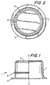
- the closure 1 comprises a collar 2 and a seal 3.
- a circumferentially and radially outwardly extending flange 4 under or over which a container (not shown) can be sealingly fixed.
- the container may be flexible or otherwise.
- the container, collar and seal comprise together a sterilisable transportable system usable for transporting sterile materials through an unsterile environment to or from a sterile or clean process area.
- the collar 2 is provided on its exterior facing surface with a circumferentially extending projection 5, which serves to help prevent the disengagement of the closure 1 from a port of a process area after docking has been established, as will be described below with reference to Figures 5 and 6.
- Seal 3 comprises a lid 31 having a flat surface 32 which faces the port during docking.
- the rim 33 of the lid 31 is formed integrally and continually with the upper wall portion 21 of the collar 2.
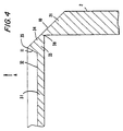
- the junction 36 between wall 21 and lid 31 is formed, on its outwardly facing side, as a frustoconical surface 10 tapering towards the apex 35 of a grippable ridge 34 of the lid 31.
- Ridge 34 is formed about the circumference of the lid surface 32 and stands proud of the rim 33.
- the surface 11 of the inside wall of ridge 34 tapers from surface 32 toward the apex 35.
- a relatively thin-walled junction 36 is formed between collar 2 and lid 31.
- This junction 36 represents a point of weakness or a fracture line (36) which can be exploited to enable the lid 31 to be torn from the collar 2.
- This is achieved by applying a double jawed gripping tool ( Figure 7) to the ridge 34 so as to engage one jaw of the tool against the outwardly facing sloping surface 10 of the ridge 34 and the second jaw against the inwardly facing sloping surface 11 of the ridge 34.
- the jaws are preferably toothed. Then, by applying a force to the tool in the direction of the arrow A ( Figure 4), the thin wall at junction 36 is ruptured by the jaws. The lid 31 may then be removed intact by peeling it away from the collar 2, rupturing along the fracture line formed by the thin wall.
- one suitable arrangement of the ridge 34 is where the angle between the frustoconical surface 10 and the surface 32 is 45°.
- Other suitable dimensions for one arrangement of the collar are also shown in the Figure and it is to be understood that these dimensions are exemplary in nature and not to be in any way considered as limiting.
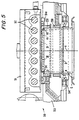
- FIGS 5 and 6 demonstrate the docking of the assembly 1 with a port such as that described in WO96/21615.
- Port 50 is fully described in that document and accordingly will now be described only insofar as necessary to convey a full appreciation of the invention disclosed herein.
- port 50 includes a door 51, shown closed in Figures 5 and 6.
- On the outwardly facing side 51a of the door are mounted seven UV lamps 52.
- Sleeve 53 of the port 50 is adapted to receive the collar 2 and to lock it into position coupled with the port shown in Figures 5 and 6.
- a locking mechanism is actuable to engage the external surface of the collar wall 2 between projection 5 and flange 4, to retain the collar 2 in place and to prevent it from accidentally disengaging from the port 50 during a transfer.
- the projection 5 extends around the entire outer circumference of the collar 2, it will be appreciated that there is no need to offer up the collar 2 to the port 50 in any particular rotation about the longitudinal axis x of the collar ( Figure 1) and this feature allows for easy and speedy establishment of docking between the collar 2 and port 50.
- various seals are actuated to bear between the exterior of the collar 2 and the interior of the port 50. thus forming a sealed connection chamber 55 between the mouth area of the collar 2, the exterior of the lid 31 and the door 51 of the port 50.
- the secondary environmental seal 250 is inflated, sealing the transfer interface. The pressure in the secondary seal is verified as correct according to specification and constant.
- the UV lamps 52 are activated to sterilise the vertical contact surface between the primary environmental seal 251 and the horizontal interface surface of collar 2, including lid 31. After a predetermined time and with the UV lamps 52 remaining activated. the primary environmental seal 251 is inflated.
- Irradiation is continued for a predetermined period of time sufficient to sterilise the volume enclosed by the chamber 55, together with the exposed surfaces of the port 50, collar 2, primary environmental seal 251 and lid 31, to achieve a reduction of contaminants by at least a factor of 10 -6 .
- door 51 may be safely opened inwardly into the process areas. It will be appreciated that all surfaces which form part of the chamber 55 are directly exposed in the path of the UV radiation generated by lamps 52 and no potentially contaminated surfaces of the sleeve 53, door 51, collar 2 or lid 31 which become continuous with the process area on opening of the door 51 are shadowed from the sterilising radiation.
- the tapering surfaces 10, 11 and the lid surface 32 are so formed that all parts of the collar 2 receive the sterilising radiation impacting directly on them.
- the collar 2 may be formed so that its exterior facing wall tapers toward the upper wall portion 21, for example by a 2° slope. The slope in the wall of the collar would further facilitate the sterilisation of the surface of the exterior wall of collar 2.
- an operator working within the process area may reach through with the gripping tool as shown in Figure 7 and use it to grasp the ridge 34 anywhere about its circumferential length.
- the operator is enabled to break the lid 31 from the collar as described above, to remove it completely from the collar and to withdraw it into the process area.
- the lid 31 thus may be cleanly removed without the generation of particulates. Free access between the interior of the container C sealed to the flange 4 of the collar is thereafter available.
- a gripping tool suitable for removing the lid 31 is shown in Figure 7.
- the tool 800 has a pair of legs 801, 802 each of which has a handle 803. Distal each handle 803 is a jaw, leg 801 having jaw 804 and leg 802 having jaw 805.
- the legs 801, 802 are pivoted together for relative movement.
- jaw 805 bears against the inwardly sloping surface 11 of the ridge 34
- jaw 804 bears against the outwardly sloping surface of the ridge 34.
- the force applied to the ridge 34 serves to break it at its weakest point, that is to say, at junction 36. Once the break has been made, the lid 31 may be peeled off with the jaws gripping the ridge.
- the tool 800 may be operated manually or may be arranged for automatic operation. In the latter case, the tool 800 may be connected to the port of the clean, process enclosure area.
- this may advantageously be achieved by flat welding a planar surface of the container to a planar surface of the flange 4. This may be done automatically using a welding tool which has an unbroken welding surface shaped to match that of the face of the flange 4 to which the container is to be attached, resulting in a high quality, secure weld being formed. Such a weld enables checking for leaks between the container and the closure to be done by spot-checking randomly selected containers, rather than, as before, checking each individual container for leaks.
- the container is a flexible bag with a mouth wider than the width of the closure.
- the material of the bag is gathered manually about the closure.
- the presence of the gathers makes it difficult to carry out the welding step using a single tool and a single weld. so that the weld must be made manually in a series of welding steps.
- the manual operation can vary from container to container and consequently verification of the weld and of the integrity of the resulting container can not be done on the basis of testing randomly selected containers.
- each container must be checked for leaks at the interface between container material and the container closure and this places a high cost burden on the manufacture of such bags.
- the significant manual intervention required poses an unacceptably high risk of introduction of both viable and non-viable particulate contaminants.
- the container manufacture in its totality can be performed under class 100 clean conditions. Both the manufacture of the container itself and the attachment of the container closure can be carried out automatically in-line. Operator intervention is minimal and hence, the introduction of viable and non-viable particulates is minimised and the costs associated with manual assembly are reduced. Additionally, significant savings are obtained by eliminating the need to check each final container for leaks.
- Figure 10 shows a modification of the collar 2 in which flange 41 is formed with sloped walls.
- the sloped walls of the flange 41 are suitable to receive the container connected thereto by a welding or other bonding process.
- the lid 31 is integrally formed with the walls of the collar and that no tab or other structure is present which could, in use when docked, be shadowed from the sterilising radiation.
- the construction is such that all surfaces which become part of the process area on completion of the docking cycle are in the direct path of the sterilising radiation.
- the lid covering the collar can easily be removed without generation of particulates.
- the closure of the invention may equally be used in docking systems which use sterilising means in addition to or other than UV or pulsed white light, for example, in systems which use steam or sterilising gases to sterilise the coupled port and container interface.
- the lid and collar may be formed integrally, for example by injection or other moulding with suitable plastics materials. Equally, they may be bonded together with a suitably formed area of weakness to define the fracture line which can be easily breakable to enable separation of lid from collar, or may be formed in any other suitable way. Likewise, the lid may be formed wholly separately from the collar and be adapted to fit with the collar in some suitable way, such as by an interference or a screw fit.
- the arrangements in which the lid and collar are connected by being formed together, such as by bonding or by being integrally formed, are preferred, since containers using this preferred arrangement can readily be inspected to ensure that the connection between the lid and collar is unbroken and hence the sterile status of the interior of the container has not been intentionally or unintentionally compromised.
- the grip or ridge of the lid may be formed with any other suitable profile other than the triangular cross-section shown in the drawings. For example, it may have a rounded or humped shape. It may also be formed about only a part of the rim of the lid, or may be positioned not on the circumference of the lid, but elsewhere on its surface, for example as a central stud.
- the grip is particularly preferred that the grip be provided as a ridge extending about the entire rim of the lid, as this obviates any need to locate the collar in any particular rotation within the dock and accounts for its easy accessibility for left- and right-handed persons.
- the lid and collar portions need not be formed with a generally circular cross-sectional shape. Any other suitable shape, including square, rectangular. triangular, oval etc., may be selected.
- the circular shape is a particularly preferred arrangement since it avoids the need for the collar to be offered up to the port in any particular axial rotation.
- the transportable container will be manufactured with the intact closure arranged about a discharge opening of the container, and a further opening provided elsewhere in the container to enable the container to be charged with materials or components. Once charged, the further opening will be sealed and the container subjected to sterilisation. Only when the contents are to be withdrawn therefore, need the closure be interfered with to remove the lid and to enable the contents to be accessed from the interior of the process area.
- the container may have one or more closures formed in it.
- One closure may be employed for aseptically charging a pre-sterilised container, then that closure would be sealed.
- a second closure may be provided to enable a portion of the contents of the bag to be discharged and third and further closures could be provided to allow remaining contents or portions thereof to be discharged at a later time or times.
- the collar is advantageously provided with a sealable cap 60 to protect the closure from mechanical damage, dust, dirt and so on during transit and storage.
- the cap 60 would also serve to limit the biological burden on the collar parts which become exposed during a transfer and for this purpose, the cap 60 is designed to cover and protect those parts of the collar and lid which form part of the sterile connection chamber on docking of the container with the port of the sterile or clean room.
- the cap 60 is disposed to rest against the circumferentially extending projection 5, thus ensuring that the travel of the cap 60 over the closure 1 is limited and that the cap may not be pressed sufficiently over the collar so as to risk damaging the lid 31.
- the cap may be sealed to the collar with tape (not shown) or may be pressed over the collar as a snap-fit or both.
- the sealing tape may be of a heat or radiation sensitive type, depending on the sterilising method employed to sterilise the container so that an operator can tell at a glance that the sealed container has undergone a sterilisation cycle.
- those parts of the apparatus under the cap will be sterilised during the sterilisation cycle.
- the cap may be provided with a panel of a material which is porous to gas, such as sterilising steam, but impervious to biological contaminants and which would therefore allow gas generated during sterilisation to be vented from the interior of the container.
- Tyvec Trade Mark
- the collar may be provided with a sensor co-operable with sensing means which may be provided in the port of the process area.
- a sensor could provide a number of functions, including but not limited to enabling the operator to ensure that the collar is correctly engaged in the port and the accumulation of tracking records, for example by enabling a record of which individually coded containers and which number of containers have been processed via a particular port to be kept.
Landscapes
- Engineering & Computer Science (AREA)
- Mechanical Engineering (AREA)
- Closures For Containers (AREA)
- Cartons (AREA)
- Packages (AREA)
Claims (14)
- Ein Verschluß (1) für einen transportfähigen Behälter, der bei der Übertragung von Material zu oder von einem sterilen oder sauberen Prozeßbereich über eine nichtsterile Umgebung verwendbar ist, wobei der Verschluß mit einem Tor andockbar ist, das in einer Wand des Prozessorbereichs positioniert ist, um eine abgedichtete Verbindungskammer zu bilden, wobei der Verschluß einen Einfassungsabschnitt (2), der angeordnet ist, um sich mit dem Tor zu verriegeln, und einen Deckelabschnitt (31) umfaßt, der entfernbar mit dem Einfassungsabschnitt verbunden ist, wobei die Anordnung derart ist, daß nach dem Verschließen des Verschlusses mit dem Tor und der Sterilisation der abgedichteten Verbindungskammer der Deckelabschnitt von innerhalb des Prozeßbereichs entfernbar ist, um eine Kommunikation zwischen dem Inneren des Behälters und dem Prozeßbereich zu liefern, dadurch gekennzeichnet, daß der Einfassungs- und der Deckelabschnitt (2, 31) so gebildet und geformt sind, daß (i) alle Oberflächen derselben, die einen Teil der abgedichteten Verbindungskammer bilden, in der Verwendung in dem direkten Weg von sterilisierender ultravioletter oder gepulster weißer Lichtstrahlung liegen, die in der Kammer erzeugt wird, ohne daß eine Oberfläche oder ein Abschnitt einer Oberfläche von der Strahlung beschattet wird, und (ii) der Deckelabschnitt ohne die Erzeugung von Partikelmaterial entfernbar ist, und der Deckelabschnitt ein Greifbauglied (34) umfaßt, das greifbar ist, um die Entfernung des Deckelabschnitts von dem Einfassungsabschnitt zu unterstützen, wobei die Verbindung (36) zwischen dem Deckel- und dem Einfassungsabschnitt ein dünnes zerbrechliches Netz oder Material umfaßt, das eine Bruchlinie zwischen den beiden Abschnitten definiert, und wobei das Greifbauglied angeordnet ist, so daß, wenn dasselbe in einer Richtung weg von dem Einfassungsabschnitt gezogen wird, bewirkt wird, daß das Netz entlang der Bruchlinie bricht, um den Deckelabschnitt von dem Einfassungsabschnitt zu lösen, wobei der Einfassungsabschnitt mit einer äußeren Oberfläche (10) gebildet ist, die sich zu der Verbindung mit dem Deckelabschnitt hin verjüngt.
- Ein Verschluß gemäß Anspruch 1, der aus einem Kunststoffmaterial hergestellt ist.
- Ein Verschluß gemäß Anspruch 2, bei dem sich die verjüngende Oberfläche (10) über die Verbindung und über dieselbe hinaus fortsetzt, durch die Bereitstellung einer passenden Verjüngung an der äußeren Oberfläche des Randes (33) des Deckelabschnitts.
- Ein Verschluß gemäß einem der vorhergehenden Ansprüche, bei dem der Deckelabschnitt eine planare Oberfläche (32) aufweist, die die Mündung der Einfassung bedeckt, und die dem verwendeten Tor zugewandt ist.
- Ein Verschluß gemäß Anspruch 4, bei dem das Greifbauglied der planaren Oberfläche zugeordnet ist.
- Ein Verschluß gemäß einem der vorhergehenden Ansprüche, bei dem das Greifbauglied um zumindest einen Abschnitt des Randes des Deckelabschnitts angeordnet ist.
- Ein Verschluß gemäß einem der vorhergehenden Ansprüche, bei dem das Greifbauglied im Querschnitt im wesentlichen dreieckig ist, wobei eine Seite des Dreiecks eine sich verjüngende äußere Oberfläche des Dekkelrandes umfaßt.
- Ein Verschluß gemäß einem der vorhergehenden Ansprüche, bei dem die Einfassung mit einem Flansch (4, 41) versehen ist, der abdichtbar mit einer Oberfläche des Behälters verbindbar ist.
- Ein Verschluß gemäß Anspruch 8, bei dem sich der Flansch von dem Einfassungsabschnitt radial nach außen erstreckt.
- Ein Verschluß gemäß Anspruch 9, bei dem der Flansch einstückig mit dem Einfassungsabschnitt gebildet ist.
- Ein Verschluß gemäß einem der Ansprüche 8 bis 10, bei dem der Flansch eine planare Oberfläche aufweist, die abdichtbar mit einer planaren Oberfläche des Behälters verbindbar ist.
- Ein Verschluß gemäß einem der Ansprüche 8 bis 11, bei dem der Behälter und der Flansch aneinandergeschweißt sind.
- Ein Verschluß gemäß einem der vorhergehenden Ansprüche, der eine Sensoreinrichtung umfaßt, die mit einer Erfassungsvorrichtung verbindbar ist, die in dem Tor vorgesehen ist.
- Ein transportierbarer Behälter, der einen Verschluß gemäß einem der vorhergehenden Ansprüche aufweist.
Applications Claiming Priority (3)
| Application Number | Priority Date | Filing Date | Title |
|---|---|---|---|
| IE970068 IES80564B2 (en) | 1997-02-04 | 1997-02-04 | A removable closure for a container |
| IE970068 | 1997-02-04 | ||
| PCT/IE1998/000006 WO1998033719A1 (en) | 1997-02-04 | 1998-02-04 | Tear-open closure for a container |
Publications (2)
| Publication Number | Publication Date |
|---|---|
| EP1015342A1 EP1015342A1 (de) | 2000-07-05 |
| EP1015342B1 true EP1015342B1 (de) | 2003-09-03 |
Family
ID=11041365
Family Applications (1)
| Application Number | Title | Priority Date | Filing Date |
|---|---|---|---|
| EP98903271A Expired - Lifetime EP1015342B1 (de) | 1997-02-04 | 1998-02-04 | Behälter mit aufreissöffnung |
Country Status (9)
| Country | Link |
|---|---|
| US (1) | US6192948B1 (de) |
| EP (1) | EP1015342B1 (de) |
| JP (2) | JP4208261B2 (de) |
| AT (1) | ATE248757T1 (de) |
| AU (1) | AU6004598A (de) |
| DE (1) | DE69817842T2 (de) |
| ES (1) | ES2206888T3 (de) |
| IE (1) | IES80564B2 (de) |
| WO (1) | WO1998033719A1 (de) |
Families Citing this family (7)
| Publication number | Priority date | Publication date | Assignee | Title |
|---|---|---|---|---|
| US6849233B2 (en) | 2001-02-26 | 2005-02-01 | Purepulse Technologies, Inc. | Vacuum sterilized sealing of passthrough light treatment devices |
| EP1556092A1 (de) * | 2002-10-29 | 2005-07-27 | Millipore Corporation | Autoklavierbarer steriler transferbeutel mit prüfbarer integrität |
| JP2005098229A (ja) * | 2003-09-25 | 2005-04-14 | Toyoda Gosei Co Ltd | 燃料タンク用継手 |
| US7692159B2 (en) * | 2006-06-26 | 2010-04-06 | Microsoft Corporation | Self-sterilizing input device |
| CH715184A1 (de) | 2018-07-18 | 2020-01-31 | Pharma Integration S R L | Anordnung zum kontaminationsfreien Einschleusen eines sterilen Objektes aus einem Behältnis in ein Containment und Verfahren dazu. |
| GB2592416B (en) | 2020-02-27 | 2022-08-03 | Douwe Egberts Bv | Improvements in or relating to capsule filling lines |
| US11679171B2 (en) | 2021-06-08 | 2023-06-20 | Steribin, LLC | Apparatus and method for disinfecting substances as they pass through a pipe |
Family Cites Families (9)
| Publication number | Priority date | Publication date | Assignee | Title |
|---|---|---|---|---|
| BE546400A (de) | ||||
| GB688534A (en) | 1949-03-08 | 1953-03-11 | Irvin Henry Rieke | Improvements in pouring spouts for liquid containers |
| US4355729A (en) * | 1981-01-15 | 1982-10-26 | Maguire Daniel J | Single service childproof closure |
| FR2613526B1 (fr) * | 1987-04-02 | 1989-06-16 | Euritech | Dispositif deconnectable pour mettre en communication deux volumes clos |
| DE68924847T2 (de) * | 1988-02-16 | 1996-07-04 | Now Technologies Inc | Behälter und verabreichungssystem für flüssige chemikalien. |
| US5056659A (en) * | 1988-09-28 | 1991-10-15 | Howes James P | Prize holding container assemblies |
| US4903855A (en) * | 1988-11-25 | 1990-02-27 | Baxter International Inc. | Closure and port assembly |
| GB2237816A (en) * | 1989-11-09 | 1991-05-15 | Cambridge Isolation Tech | Isolator transfer containers |
| EP0800480B1 (de) * | 1995-01-13 | 1999-04-28 | Duras Trading Limited | Kupplungsanordnung zur sterilen übergabe von sterilen materialien zwischen einem transportablen behälter und einem sterilen gehäuse |
-
1997
- 1997-02-04 IE IE970068 patent/IES80564B2/en not_active IP Right Cessation
-
1998
- 1998-02-04 JP JP53268398A patent/JP4208261B2/ja not_active Expired - Fee Related
- 1998-02-04 AU AU60045/98A patent/AU6004598A/en not_active Abandoned
- 1998-02-04 EP EP98903271A patent/EP1015342B1/de not_active Expired - Lifetime
- 1998-02-04 ES ES98903271T patent/ES2206888T3/es not_active Expired - Lifetime
- 1998-02-04 DE DE69817842T patent/DE69817842T2/de not_active Expired - Lifetime
- 1998-02-04 AT AT98903271T patent/ATE248757T1/de not_active IP Right Cessation
- 1998-02-04 US US09/355,819 patent/US6192948B1/en not_active Expired - Lifetime
- 1998-02-04 WO PCT/IE1998/000006 patent/WO1998033719A1/en not_active Ceased
-
2008
- 2008-01-29 JP JP2008018301A patent/JP4581144B2/ja not_active Expired - Fee Related
Also Published As
| Publication number | Publication date |
|---|---|
| DE69817842D1 (de) | 2003-10-09 |
| DE69817842T2 (de) | 2004-07-29 |
| ES2206888T3 (es) | 2004-05-16 |
| IES80564B2 (en) | 1998-09-23 |
| JP4208261B2 (ja) | 2009-01-14 |
| EP1015342A1 (de) | 2000-07-05 |
| IES970068A2 (en) | 1998-08-12 |
| JP2001509758A (ja) | 2001-07-24 |
| US6192948B1 (en) | 2001-02-27 |
| ATE248757T1 (de) | 2003-09-15 |
| WO1998033719A1 (en) | 1998-08-06 |
| JP4581144B2 (ja) | 2010-11-17 |
| AU6004598A (en) | 1998-08-25 |
| JP2008150117A (ja) | 2008-07-03 |
Similar Documents
| Publication | Publication Date | Title |
|---|---|---|
| US6793882B1 (en) | Sterilization container | |
| US6030578A (en) | Coupling assembly for the sterile transfer of sterile materials between a transportable container and a sterile enclosure | |
| CA2577905C (en) | Cap assembly and container used therewith | |
| EP1014866B1 (de) | Sterile verpackung für spritzen | |
| US6234310B1 (en) | Sterile packaging system | |
| JP6796579B2 (ja) | 滅菌容器、滅菌方法及び滅菌装置 | |
| US20060249533A1 (en) | Cap assembly and container used therewith | |
| JP4581144B2 (ja) | コンテナのための、剥ぎ取り式のクロージャ | |
| US6749808B1 (en) | Sterilizable container with a sterilizable adapter for docking to a port of an isolation system | |
| JP2019508326A (ja) | 取付け具を備えたパウチおよびパウチを作製する方法 | |
| JP2003528009A (ja) | いたずら防止シールおよびその使用法 | |
| JPH11507255A (ja) | 皮下投与および薬品分与システム用の多目的瓶 | |
| WO1997026941A1 (en) | Double seal cap | |
| EP0997155B1 (de) | Sterilisierbarer Behälter mit sterilisierbarem Adapter zum Ankoppeln an den Eingang einer Trennkammer | |
| JPS62208332A (ja) | 容器に無菌で充填する方法及びそのシステム | |
| US20230061991A1 (en) | Labelling arrangement for a multi-part container, system and method for applying a labelling arrangement to a multi-part container | |
| US11027869B2 (en) | Method for separate sterilization and aseptic assembly | |
| AU774131B2 (en) | Sterilization container | |
| IES68444B2 (en) | Process containment apparatus | |
| EP3405402A1 (de) | Beutel mit aufsatz und verfahren zur herstellung davon | |
| HK1259105B (zh) | 一种用於多部件医疗装置的无菌组装的方法及其套件 |
Legal Events
| Date | Code | Title | Description |
|---|---|---|---|
| PUAI | Public reference made under article 153(3) epc to a published international application that has entered the european phase |
Free format text: ORIGINAL CODE: 0009012 |
|
| 17P | Request for examination filed |
Effective date: 19990903 |
|
| AK | Designated contracting states |
Kind code of ref document: A1 Designated state(s): AT BE CH DE DK ES FR GB IE IT LI NL SE |
|
| 17Q | First examination report despatched |
Effective date: 20010403 |
|
| RAP1 | Party data changed (applicant data changed or rights of an application transferred) |
Owner name: MILLIPORE IRELAND B.V. |
|
| GRAH | Despatch of communication of intention to grant a patent |
Free format text: ORIGINAL CODE: EPIDOS IGRA |
|
| GRAH | Despatch of communication of intention to grant a patent |
Free format text: ORIGINAL CODE: EPIDOS IGRA |
|
| GRAA | (expected) grant |
Free format text: ORIGINAL CODE: 0009210 |
|
| RTI1 | Title (correction) |
Free format text: TEAR-OPEN CLOSURE FOR A CONTAINER |
|
| AK | Designated contracting states |
Kind code of ref document: B1 Designated state(s): AT BE CH DE DK ES FR GB IE IT LI NL SE |
|
| PG25 | Lapsed in a contracting state [announced via postgrant information from national office to epo] |
Ref country code: AT Free format text: LAPSE BECAUSE OF FAILURE TO SUBMIT A TRANSLATION OF THE DESCRIPTION OR TO PAY THE FEE WITHIN THE PRESCRIBED TIME-LIMIT Effective date: 20030903 |
|
| REG | Reference to a national code |
Ref country code: GB Ref legal event code: FG4D |
|
| REG | Reference to a national code |
Ref country code: CH Ref legal event code: EP |
|
| REF | Corresponds to: |
Ref document number: 69817842 Country of ref document: DE Date of ref document: 20031009 Kind code of ref document: P |
|
| REG | Reference to a national code |
Ref country code: IE Ref legal event code: FG4D |
|
| REG | Reference to a national code |
Ref country code: CH Ref legal event code: NV Representative=s name: NOVARTIS AG |
|
| PG25 | Lapsed in a contracting state [announced via postgrant information from national office to epo] |
Ref country code: SE Free format text: LAPSE BECAUSE OF FAILURE TO SUBMIT A TRANSLATION OF THE DESCRIPTION OR TO PAY THE FEE WITHIN THE PRESCRIBED TIME-LIMIT Effective date: 20031203 Ref country code: DK Free format text: LAPSE BECAUSE OF FAILURE TO SUBMIT A TRANSLATION OF THE DESCRIPTION OR TO PAY THE FEE WITHIN THE PRESCRIBED TIME-LIMIT Effective date: 20031203 |
|
| ET | Fr: translation filed | ||
| REG | Reference to a national code |
Ref country code: ES Ref legal event code: FG2A Ref document number: 2206888 Country of ref document: ES Kind code of ref document: T3 |
|
| PLBE | No opposition filed within time limit |
Free format text: ORIGINAL CODE: 0009261 |
|
| STAA | Information on the status of an ep patent application or granted ep patent |
Free format text: STATUS: NO OPPOSITION FILED WITHIN TIME LIMIT |
|
| 26N | No opposition filed |
Effective date: 20040604 |
|
| PG25 | Lapsed in a contracting state [announced via postgrant information from national office to epo] |
Ref country code: IE Free format text: LAPSE BECAUSE OF NON-PAYMENT OF DUE FEES Effective date: 20050204 |
|
| REG | Reference to a national code |
Ref country code: IE Ref legal event code: MM4A |
|
| PGFP | Annual fee paid to national office [announced via postgrant information from national office to epo] |
Ref country code: IE Payment date: 20040229 Year of fee payment: 7 |
|
| REG | Reference to a national code |
Ref country code: GB Ref legal event code: 732E Free format text: REGISTERED BETWEEN 20100408 AND 20100414 |
|
| REG | Reference to a national code |
Ref country code: FR Ref legal event code: TP |
|
| REG | Reference to a national code |
Ref country code: NL Ref legal event code: SD Effective date: 20100625 |
|
| REG | Reference to a national code |
Ref country code: CH Ref legal event code: PUE Owner name: TULLAGREEN HOLDINGS LIMITED Free format text: MILLIPORE IRELAND B.V.#TULLAGREEN#CARRIGTWOHILL, COUNTY CORK (IE) -TRANSFER TO- TULLAGREEN HOLDINGS LIMITED#FITZWILTON HOUSE WILTON PLACE#DUBLIN 2 (IE) Ref country code: CH Ref legal event code: NV Representative=s name: BOVARD AG PATENTANWAELTE |
|
| REG | Reference to a national code |
Ref country code: CH Ref legal event code: PUE Owner name: MILLIPORE IRELAND LIMITED TULLAGREEN Free format text: TULLAGREEN HOLDINGS LIMITED#FITZWILTON HOUSE WILTON PLACE#DUBLIN 2 (IE) -TRANSFER TO- MILLIPORE IRELAND LIMITED TULLAGREEN#CARRIGTWOHILL#COUNTY CORK (IE) |
|
| REG | Reference to a national code |
Ref country code: NL Ref legal event code: SD Effective date: 20100726 |
|
| REG | Reference to a national code |
Ref country code: FR Ref legal event code: TP |
|
| REG | Reference to a national code |
Ref country code: GB Ref legal event code: 732E Free format text: REGISTERED BETWEEN 20100729 AND 20100804 |
|
| REG | Reference to a national code |
Ref country code: ES Ref legal event code: PC2A Owner name: MILLIPORE IRELAND LIMITED Effective date: 20110218 |
|
| REG | Reference to a national code |
Ref country code: CH Ref legal event code: PFA Owner name: MILLIPORE IRELAND LIMITED TULLAGREEN Free format text: MILLIPORE IRELAND LIMITED TULLAGREEN#CARRIGTWOHILL#COUNTY CORK (IE) -TRANSFER TO- MILLIPORE IRELAND LIMITED TULLAGREEN#CARRIGTWOHILL#COUNTY CORK (IE) |
|
| REG | Reference to a national code |
Ref country code: NL Ref legal event code: TD Effective date: 20120126 |
|
| REG | Reference to a national code |
Ref country code: CH Ref legal event code: PFA Owner name: MERCK MILLIPORE LIMITED Free format text: MILLIPORE IRELAND LIMITED TULLAGREEN#CARRIGTWOHILL#COUNTY CORK (IE) -TRANSFER TO- MERCK MILLIPORE LIMITED#CARRIGTWOHILL#COUNTY CORK (IE) |
|
| REG | Reference to a national code |
Ref country code: DE Ref legal event code: R082 Ref document number: 69817842 Country of ref document: DE Representative=s name: SCHOPPE, ZIMMERMANN, STOECKELER, ZINKLER & PAR, DE Effective date: 20120202 Ref country code: DE Ref legal event code: R082 Ref document number: 69817842 Country of ref document: DE Representative=s name: SCHOPPE, ZIMMERMANN, STOECKELER, ZINKLER, SCHE, DE Effective date: 20120202 Ref country code: DE Ref legal event code: R081 Ref document number: 69817842 Country of ref document: DE Owner name: MERCK MILLIPORE LIMITED, IE Free format text: FORMER OWNER: MILLIPORE IRELAND LTD., CARRIGTWOHILL, IE Effective date: 20120202 Ref country code: DE Ref legal event code: R081 Ref document number: 69817842 Country of ref document: DE Owner name: MERCK MILLIPORE LIMITED, CARRIGTWOHILL, IE Free format text: FORMER OWNER: MILLIPORE IRELAND LTD., CARRIGTWOHILL, COUNTRY CORK, IE Effective date: 20120202 |
|
| REG | Reference to a national code |
Ref country code: FR Ref legal event code: CD Owner name: MERCK MILLIPORE LIMITED, IE Effective date: 20120221 |
|
| REG | Reference to a national code |
Ref country code: ES Ref legal event code: PC2A Owner name: MERCK MILLIPORE LIMITED Effective date: 20120411 |
|
| PGFP | Annual fee paid to national office [announced via postgrant information from national office to epo] |
Ref country code: NL Payment date: 20140110 Year of fee payment: 17 Ref country code: DE Payment date: 20140129 Year of fee payment: 17 Ref country code: CH Payment date: 20140212 Year of fee payment: 17 |
|
| PGFP | Annual fee paid to national office [announced via postgrant information from national office to epo] |
Ref country code: ES Payment date: 20140113 Year of fee payment: 17 Ref country code: FR Payment date: 20140211 Year of fee payment: 17 Ref country code: BE Payment date: 20140214 Year of fee payment: 17 Ref country code: IT Payment date: 20140109 Year of fee payment: 17 |
|
| PGFP | Annual fee paid to national office [announced via postgrant information from national office to epo] |
Ref country code: GB Payment date: 20140129 Year of fee payment: 17 |
|
| PG25 | Lapsed in a contracting state [announced via postgrant information from national office to epo] |
Ref country code: BE Free format text: LAPSE BECAUSE OF NON-PAYMENT OF DUE FEES Effective date: 20150228 |
|
| REG | Reference to a national code |
Ref country code: DE Ref legal event code: R119 Ref document number: 69817842 Country of ref document: DE |
|
| REG | Reference to a national code |
Ref country code: NL Ref legal event code: V1 Effective date: 20150901 |
|
| PG25 | Lapsed in a contracting state [announced via postgrant information from national office to epo] |
Ref country code: NL Free format text: LAPSE BECAUSE OF NON-PAYMENT OF DUE FEES Effective date: 20150901 |
|
| REG | Reference to a national code |
Ref country code: CH Ref legal event code: PL |
|
| GBPC | Gb: european patent ceased through non-payment of renewal fee |
Effective date: 20150204 |
|
| PG25 | Lapsed in a contracting state [announced via postgrant information from national office to epo] |
Ref country code: CH Free format text: LAPSE BECAUSE OF NON-PAYMENT OF DUE FEES Effective date: 20150228 Ref country code: LI Free format text: LAPSE BECAUSE OF NON-PAYMENT OF DUE FEES Effective date: 20150228 |
|
| REG | Reference to a national code |
Ref country code: FR Ref legal event code: ST Effective date: 20151030 |
|
| PG25 | Lapsed in a contracting state [announced via postgrant information from national office to epo] |
Ref country code: IT Free format text: LAPSE BECAUSE OF NON-PAYMENT OF DUE FEES Effective date: 20150204 |
|
| PG25 | Lapsed in a contracting state [announced via postgrant information from national office to epo] |
Ref country code: GB Free format text: LAPSE BECAUSE OF NON-PAYMENT OF DUE FEES Effective date: 20150204 Ref country code: DE Free format text: LAPSE BECAUSE OF NON-PAYMENT OF DUE FEES Effective date: 20150901 |
|
| PG25 | Lapsed in a contracting state [announced via postgrant information from national office to epo] |
Ref country code: FR Free format text: LAPSE BECAUSE OF NON-PAYMENT OF DUE FEES Effective date: 20150302 |
|
| REG | Reference to a national code |
Ref country code: ES Ref legal event code: FD2A Effective date: 20160329 |
|
| PG25 | Lapsed in a contracting state [announced via postgrant information from national office to epo] |
Ref country code: ES Free format text: LAPSE BECAUSE OF NON-PAYMENT OF DUE FEES Effective date: 20150205 |