EP1014530A2 - Elektrische Energieverteilungsanlage für ein elektrisches Stromversorgungssystem - Google Patents
Elektrische Energieverteilungsanlage für ein elektrisches Stromversorgungssystem Download PDFInfo
- Publication number
- EP1014530A2 EP1014530A2 EP99116947A EP99116947A EP1014530A2 EP 1014530 A2 EP1014530 A2 EP 1014530A2 EP 99116947 A EP99116947 A EP 99116947A EP 99116947 A EP99116947 A EP 99116947A EP 1014530 A2 EP1014530 A2 EP 1014530A2
- Authority
- EP
- European Patent Office
- Prior art keywords
- common bus
- grounding
- bus bar
- main
- ground
- Prior art date
- Legal status (The legal status is an assumption and is not a legal conclusion. Google has not performed a legal analysis and makes no representation as to the accuracy of the status listed.)
- Granted
Links
Images

Classifications
-
- H—ELECTRICITY
- H02—GENERATION; CONVERSION OR DISTRIBUTION OF ELECTRIC POWER
- H02H—EMERGENCY PROTECTIVE CIRCUIT ARRANGEMENTS
- H02H9/00—Emergency protective circuit arrangements for limiting excess current or voltage without disconnection
- H02H9/08—Limitation or suppression of earth fault currents, e.g. Petersen coil
-
- H—ELECTRICITY
- H02—GENERATION; CONVERSION OR DISTRIBUTION OF ELECTRIC POWER
- H02J—ELECTRIC POWER NETWORKS; CIRCUIT ARRANGEMENTS OR SYSTEMS FOR SUPPLYING OR DISTRIBUTING ELECTRIC POWER; SYSTEMS FOR STORING ELECTRIC ENERGY
- H02J3/00—Circuit arrangements for AC mains or AC distribution networks
-
- H—ELECTRICITY
- H02—GENERATION; CONVERSION OR DISTRIBUTION OF ELECTRIC POWER
- H02H—EMERGENCY PROTECTIVE CIRCUIT ARRANGEMENTS
- H02H3/00—Emergency protective circuit arrangements for automatic disconnection directly responsive to an undesired change from normal electric working condition with or without subsequent reconnection ; integrated protection
- H02H3/16—Emergency protective circuit arrangements for automatic disconnection directly responsive to an undesired change from normal electric working condition with or without subsequent reconnection ; integrated protection responsive to fault current to earth, frame or mass
- H02H3/162—Emergency protective circuit arrangements for automatic disconnection directly responsive to an undesired change from normal electric working condition with or without subsequent reconnection ; integrated protection responsive to fault current to earth, frame or mass for AC systems
- H02H3/165—Emergency protective circuit arrangements for automatic disconnection directly responsive to an undesired change from normal electric working condition with or without subsequent reconnection ; integrated protection responsive to fault current to earth, frame or mass for AC systems for three-phase systems
Definitions
- the present invention relates to an electrical power distribution installation and, more particularly, to apparatus and method for grounding and protecting the electrical power distribution installation such as a power station, sub-station, and/or a power generation installation in normal service.
- Fig. 1 shows a skeleton diagram representing a previously proposed electric power distribution installation.
- two main transformers MT1 and MT2 are used to step down respectively corresponding power supply voltages from respective feeders connected to receive powers L1 and L2 into main common bus bars BUS-A and BUS-B, each of 11 kV class.
- Respective loads LOADs receive the stepped down power supply voltages from the respectively connected main common bus bars BUS-A and BUS-B.
- An interconnecting circuit breaker 52AB which is normally closed serves to interconnect one of the main common bus bars BUS-A with the other main common bus bar BUS-B.
- Each main common bus bar BUS-A and BUS-B supplies the electric power to a corresponding load connected to a low-voltage bus bar via a corresponding transformer T11 and T21.
- the other main bus bar BUS-B is connected directly to a generator common bus bar BUS-G via an interconnection feeder without passing through a step-down or step-up transformer.
- the generator common bus bar BUS-G is connected to four generators G1, G2, G3, and G4.
- Each generator G1 through G4 can be disconnected from the generator common bus bar BUS-G by means of a corresponding circuit breaker 52G1, 52G2, 52G3, and 52G4.
- Each main transformer MT1 and MT2 can be disconnected from the corresponding main common bus bars BUS-A and BUS-B by means of corresponding circuit breakers 52S1 and 52S2. It is noted that each load can be disconnected from each corresponding main common bus bar BUS-A and BUS-B by means of corresponding circuit breakers as shown in Fig. 1.
- a grounding device is installed in such a power distribution installation as shown in Fig. 1.
- the grounding device includes: a neutral grounding resistors NGR-1 and NGR-2, each grounding a neutral point of a star connection of a secondary winding of the corresponding main transformer MT1 or MT2; and a neutral grounding resistor grounding each neutral point of the generators G1 through G4 via a corresponding (vacuum) switch VS1, VS2, VS3, and VS4.
- a 900A resistance grounding system can be constituted in the power system of Fig. 1.
- the grounding device i.e., the neutral grounding resistor NGR-1 is disconnected from the power system. Consequently, the grounding system is changed to a 600A resistance grounding system in the power system.
- the grounding device i.e., the neutral grounding resistor NGR-G is also disconnected (separated) from the power system so that the grounding system is changed to a 300A resistance grounding system.
- the change of the resistance grounding system due to the separation of each or any of the neutral grounding resistors from the power system causes changes in a ground fault detection sensitivity and a ground fault detection time in a protective relay system and often allows a coordinate protection in the power system not to be maintained.
- an electric power distribution installation comprising: at least one main common bus bar; a plurality of main transformers, each main transformer being configured to step down a received power supply voltage and to supply the stepped down power supply voltage to a load via the main common bus bar; a plurality of power generators, each power generator being connected to the main common bus bar; a first grounding device including at least one grounding transformer connected to the main common bus bar, a neutral point of the grounding transformer being grounded in a form of a predetermined low impedance grounding; and a second grounding device connected to each neutral point of the power generators to always ground each neutral point directly in a form of a predetermined high resistance grounding.
- a method applicable to an electric power distribution installation comprising: at least one main common bus bar; a plurality of main transformers, each main transformer being configured to step down a received power supply voltage and to supply the stepped down power supply voltage to a load via the main common bus bar; and a plurality of power generators, each power generator being connected to a generator common bus bar and the generator common bus bar being connected to the main common bus bar, and the method comprising: providing a first grounding device including at least one grounding transformer connected to the main common bus bar, a neutral point of the grounding transformer being grounded in a form of a predetermined low impedance grounding; and providing a second grounding device connected to each neutral point of the power generators to always ground each neutral point directly in a form of a predetermined high resistance grounding.
- the four generators G1 through G4 are enabled to be a parallel operation and their one neutral point is grounded via their corresponding circuit breaker ( switch) VS1 through VS4 by means of the single neutral grounding resistor NGR-G.
- a resonance phenomenon often occurs due to a reactance in a ground fault point and a capacitance between the ground and the feeder connected to the recovered generator. This resonance phenomenon causes a high voltage surge so that a dielectric breakdown may occur in any generator and/or a switchboard.
- a method applicable to an electric power distribution installation comprising: at least one main common bus bar; a plurality of main transformers, each main transformer being configured to step down a received power supply voltage and to supply the stepped down power supply voltage to a load via the main common bus bar; and a plurality of power generators, each power generator being connected to a generator common bus bar and the generator common bus bar being connected to the main common bus bar, and the method comprising: providing a first grounding device including at least one grounding transformer connected to the main common bus bar, a neutral point of the grounding transformer being grounded in a form of a predetermined low impedance grounding; providing a second grounding device connected to each neutral point of the power generators to always ground each neutral point directly in a form of a predetermined high resistance grounding; providing a first protecting device including a ground over-current relay to a secondary feeder connecting a secondary winding of each main transformer to the main common bus bar and being enabled
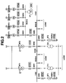
- Fig. 2 shows a skeleton diagram of a preferred embodiment of an electrical power distribution installation according to the present invention.
- each of the main common bus bars BUS-A and BUS-B is grounded in a form of a low resistance grounding (so called, a low impedance grounding) by means of a corresponding one of resistors NGR-1 and NGR-2 via a corresponding one of breakers 52S3 and 52S4 and a corresponding one of neutral grounding transformers ET1 and ET2.
- a low resistance grounding so called, a low impedance grounding
- a neutral point current to be caused to flow through each grounding resistor NGR-1 and NGR-2 is rated to be, for example, equal to 100A or larger.
- a switch gear or circuit breaker is interposed in a feeder connected to each corresponding one of grounding transformers ET1 and ET2 so that the number of the grounding transformers to be turned on to be interconnected to the corresponding one or two of the main common bus bars can be controlled to enable a modification of the grounding system of the power system shown in Fig. 2.
- each secondary winding neutral point of the main transformers MT1 and MT2 is grounded.
- each neutral point of the four generators G1 through G4 is grounded by means of a high impedance resistor (via single-phase transformers NT1 through NT4 and the secondary resistor).
- each neutral point thereof may directly be grounded by means of a corresponding one of neutral grounding resistors with a high resistance.
- each neutral point of the four generators G1 through G4 is grounded via the corresponding one of the (vacuum) switches VS1 through VS4.
- Each grounding resistance between the corresponding one of the respective neutral points of the generators G1 through G4 and the ground is determined in such a manner that the neutral point current flowing through the corresponding grounding resistor is a small current (about 10A) having a degree to which an excessive voltage is not developed across any generator even with a resonance condition established when a one-line ground occurs in the corresponding feeder to be connected to the corresponding one of the generators G1 through G4.
- This grounding device serves merely to prevent the occurrence of the resonance phenomenon and constitutes basically a non-grounding system. Consequently, the influence of the different number of the turned on generators on the grounding system can be eliminated.
- the grounding devices constitute the non-grounding system when the circuit breaker of the respective generator feeder is open.
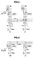
- the respective common bus bars BUS-A and BUS-B are interconnected as a low impedance grounding system).
- the ground fault current is developed in a path shown by arrow marks of Fig. 3, the ground fault over-current relay 51G1 located on the secondary winding of the one of the main transformers MT1 trips to separate the main transformer MT1 from the power system so that the sole run of the other main transformer MT2 is switched to be continued to run.
- the ground fault current is developed in the path shown by the arrow marks in Fig. 4.
- the zero-phase current in a downward direction occurs as viewed from the ground directional relay 67G1
- the zero-phase current in an upward direction occurs as viewed from the ground directional relay 67G2.
- the ground directional relay 67G1 can detect the feeder at which the ground fault occurs.
- the grounding transformer ET1 can be separated from the main common bus bar BUS-A with the trip of the breaker 52S3, the grounding system of the power system is changed.
- an alarm may preferably be produced through the ground directional relay 67G1 to inform the operator of the ground fault.
- ground fault over-current relays 51G3 and 51G4 are used to back-up the grounding system and grounding devices.
- the ground fault over-current relay 51G5 is operated so as to protect the interconnection feeder from the ground fault in response to the ground fault current flowing through the grounding transformer connected to the main common bus bar.
- the ground directional relay 67G3 detects the ground fault according to the magnitude of the zero-phase current from the feeder of the generator G1 and causes the circuit breaker 52G1 to be tripped so that only the generator G1 can be separated from the generator common bus BUS-G.
- the ground directional relay can detect in which of the feeders connected to the respectively corresponding generators the ground fault occurs.
- the ground fault can accurately be detected without a saturation of the zero-phase current transformer (balance core CT).
- the neutral points of the respective generators G1 through G4 are always grounded (always means at any time) by means of high impedance resistor (via single-phase transformers NT1 through NT4 and the secondary resistors), the overheat of each or any one of the generators G1 through G4 due to their corresponding neutral point currents (the zero-phase circulation current) can be prevented.
- the grounding device can prevent the resonance grounding
- the resonance voltage can prevent the resonance voltage from being developed in the corresponding generator and can prevent the dielectric breakdown from occurring in each generator or switchboard.
- the main common bus bars are grounded in the form of the low resistance grounding via the neutral ground transformers and each generator is grounded by the high impedance resistor to prevent the resonance phenomenon.
- the change in the grounding current can be eliminated or reduced even when the change in the number of parallel banks due to the separation of one of the main transformers, the stable grounding system can be achieved even if the failure occurs in the power system of the electrical power distribution installation, and the grounding system cannot give an influence on the coordinate protection.
- the secondary neutral point in each of the main transformers MT1 and MT2 since the secondary neutral point in each of the main transformers MT1 and MT2 is not used, the secondary winding thereof can be formed in a delta connection, and in a case where a primary winding thereof can be formed in a star connection, and a drawing out of the corresponding neutral point is required, a cost reduction according to no necessity of a stable winding can be achieved.
- each neutral point of the generators is always connected through the corresponding resonance preventing resistor, the neutral point switches or its switching control devices are not needed.
Landscapes
- Engineering & Computer Science (AREA)
- Power Engineering (AREA)
- Emergency Protection Circuit Devices (AREA)
- Supply And Distribution Of Alternating Current (AREA)
Applications Claiming Priority (2)
| Application Number | Priority Date | Filing Date | Title |
|---|---|---|---|
| JP10363633A JP2000188825A (ja) | 1998-12-22 | 1998-12-22 | 受配電設備の接地方式及び保護方式 |
| JP36363398 | 1998-12-22 |
Publications (3)
| Publication Number | Publication Date |
|---|---|
| EP1014530A2 true EP1014530A2 (de) | 2000-06-28 |
| EP1014530A3 EP1014530A3 (de) | 2006-12-13 |
| EP1014530B1 EP1014530B1 (de) | 2010-03-24 |
Family
ID=18479801
Family Applications (1)
| Application Number | Title | Priority Date | Filing Date |
|---|---|---|---|
| EP99116947A Expired - Lifetime EP1014530B1 (de) | 1998-12-22 | 1999-08-27 | Elektrische Energieverteilungsanlage für ein elektrisches Stromversorgungssystem |
Country Status (4)
| Country | Link |
|---|---|
| US (1) | US6452769B1 (de) |
| EP (1) | EP1014530B1 (de) |
| JP (1) | JP2000188825A (de) |
| DE (1) | DE69942171D1 (de) |
Cited By (5)
| Publication number | Priority date | Publication date | Assignee | Title |
|---|---|---|---|---|
| RU2260237C2 (ru) * | 2000-11-21 | 2005-09-10 | Национальный университет "Львивська политехника" | Электроустановка энергоблока электростанции |
| RU2261511C2 (ru) * | 2000-11-21 | 2005-09-27 | Национальный университет "Львивська политехника" | Система электроснабжения собственных нужд энергоблока электростанции |
| CN102664407A (zh) * | 2012-05-04 | 2012-09-12 | 甘肃省电力设计院 | 新能源电场升压变压器设计方法与系统 |
| CN105305431A (zh) * | 2015-11-06 | 2016-02-03 | 国网天津市电力公司 | 一种适用于城市中压配电网的雪花格式网架构建方法 |
| CN105743075A (zh) * | 2016-04-22 | 2016-07-06 | 国家电网公司 | 配电网单相弧光接地模拟装置 |
Families Citing this family (17)
| Publication number | Priority date | Publication date | Assignee | Title |
|---|---|---|---|---|
| JP4020304B2 (ja) * | 2002-08-09 | 2007-12-12 | 株式会社東芝 | 地絡方向継電器および地絡方向継電装置 |
| CN101499655B (zh) * | 2008-11-06 | 2011-02-09 | 江苏省电力公司 | 电力系统中性点接地电阻器成套装置 |
| JP5361620B2 (ja) * | 2009-09-07 | 2013-12-04 | 株式会社東芝 | 受変電設備の地絡保護システム |
| CN102005745A (zh) * | 2010-12-07 | 2011-04-06 | 傅桂兴 | 380/220v低压电网it配电系统及其漏电保护装置 |
| EP2530804A1 (de) * | 2011-06-01 | 2012-12-05 | ABB Research Ltd. | Verbesserte Erdfehlerhandhabung in Stromverteilungssystemen mit gemischten unter- und oberirdischen Stromleitungen |
| CN103050962A (zh) * | 2011-10-14 | 2013-04-17 | 安徽一天电气技术有限公司 | 接地转移电流检测补偿装置及其工作方法 |
| CN103050963A (zh) * | 2011-10-14 | 2013-04-17 | 安徽一天电气技术有限公司 | 避免直接接地消弧复归过电压的消弧装置及其工作方法 |
| CN102684598A (zh) * | 2012-06-01 | 2012-09-19 | 郭宝利 | 一种含有变频装置的大功率系统的接地电路 |
| CN103178502B (zh) * | 2012-07-23 | 2015-04-22 | 南京南瑞继保电气有限公司 | 发电机组主变压器低压侧母线单相接地保护方法 |
| US9500710B2 (en) * | 2012-10-15 | 2016-11-22 | Siemens Energy, Inc. | Generator neutral ground monitoring system and method |
| CN103532144A (zh) * | 2013-10-30 | 2014-01-22 | 国网安徽省电力公司 | 用于继电保护多级整定计算的电网模型拼接方法及系统 |
| US9755458B2 (en) | 2013-12-19 | 2017-09-05 | Kohler, Co. | Bus recovery after overload |
| CN104967107B (zh) * | 2015-06-25 | 2018-07-06 | 西安理工大学 | 一种抑制间歇性弧光接地过电压的方法 |
| JP6026068B1 (ja) * | 2016-04-22 | 2016-11-16 | 三菱電機株式会社 | 遮断器不動作保護リレーおよび保護リレーシステム |
| CN213980948U (zh) * | 2020-08-27 | 2021-08-17 | 康明斯电力公司 | 用于发电机组的容器 |
| CN213980949U (zh) | 2020-08-27 | 2021-08-17 | 康明斯电力公司 | 用于发电机组的系统 |
| CN112366746B (zh) * | 2020-10-22 | 2023-07-21 | 四川水利职业技术学院 | 一种防止已建成低压水轮发电机组中性线电流过大的方法 |
Family Cites Families (5)
| Publication number | Priority date | Publication date | Assignee | Title |
|---|---|---|---|---|
| US3702964A (en) * | 1971-06-22 | 1972-11-14 | Gen Electric | Internal static excitation system for a dynamoelectric machine |
| DE3806827A1 (de) * | 1988-03-03 | 1989-09-14 | Licentia Gmbh | Verfahren zur erfassung und begrenzung eines erdschlussstromes |
| CA2158187C (en) | 1994-09-19 | 2000-10-17 | Kiyoshi Oka | Electrical power generating installation and method of operating same |
| TW293196B (de) | 1995-04-26 | 1996-12-11 | Hitachi Ltd | |
| JP3239754B2 (ja) * | 1995-06-20 | 2001-12-17 | 株式会社日立製作所 | 限流装置 |
-
1998
- 1998-12-22 JP JP10363633A patent/JP2000188825A/ja active Pending
-
1999
- 1999-08-27 DE DE69942171T patent/DE69942171D1/de not_active Expired - Lifetime
- 1999-08-27 EP EP99116947A patent/EP1014530B1/de not_active Expired - Lifetime
- 1999-09-08 US US09/391,466 patent/US6452769B1/en not_active Expired - Lifetime
Cited By (6)
| Publication number | Priority date | Publication date | Assignee | Title |
|---|---|---|---|---|
| RU2260237C2 (ru) * | 2000-11-21 | 2005-09-10 | Национальный университет "Львивська политехника" | Электроустановка энергоблока электростанции |
| RU2261511C2 (ru) * | 2000-11-21 | 2005-09-27 | Национальный университет "Львивська политехника" | Система электроснабжения собственных нужд энергоблока электростанции |
| CN102664407A (zh) * | 2012-05-04 | 2012-09-12 | 甘肃省电力设计院 | 新能源电场升压变压器设计方法与系统 |
| CN105305431A (zh) * | 2015-11-06 | 2016-02-03 | 国网天津市电力公司 | 一种适用于城市中压配电网的雪花格式网架构建方法 |
| CN105305431B (zh) * | 2015-11-06 | 2017-08-25 | 国网天津市电力公司 | 一种适用于城市中压配电网的雪花格式网架构建方法 |
| CN105743075A (zh) * | 2016-04-22 | 2016-07-06 | 国家电网公司 | 配电网单相弧光接地模拟装置 |
Also Published As
| Publication number | Publication date |
|---|---|
| DE69942171D1 (de) | 2010-05-06 |
| EP1014530A3 (de) | 2006-12-13 |
| JP2000188825A (ja) | 2000-07-04 |
| US6452769B1 (en) | 2002-09-17 |
| EP1014530B1 (de) | 2010-03-24 |
Similar Documents
| Publication | Publication Date | Title |
|---|---|---|
| EP1014530B1 (de) | Elektrische Energieverteilungsanlage für ein elektrisches Stromversorgungssystem | |
| US6295190B1 (en) | Circuit breaker arrangement with integrated protection, control and monitoring | |
| US5905619A (en) | Arc fault detection system | |
| JP2000511400A (ja) | マルチ電源システムのための接地障害保護回路 | |
| US20150194798A1 (en) | Electrical fault protection device | |
| US7102866B2 (en) | Power line protection | |
| JPS5810934B2 (ja) | 地絡故障検出装置 | |
| US5959819A (en) | Reliable fault tolerant power supply for a protective relay | |
| US20020080535A1 (en) | Multiple ground fault trip function system and method for same | |
| US3423634A (en) | Differential relaying network | |
| EP1069665A2 (de) | Energieübertragungsleitung und Steuerverfahren | |
| US2272991A (en) | Protective system | |
| Thompson et al. | Modern protection of three-phase and spare transformer banks | |
| US2027189A (en) | Control and protection of electric circuits | |
| Relaying | Summary update of practices on breaker failure protection | |
| JPH07236226A (ja) | 地絡保護装置 | |
| Love | Ground fault protection for electric utility generating station 480-volt auxiliary power systems | |
| JP2705198B2 (ja) | 地絡検出装置 | |
| Griffin | Relay protection of generator station service transformers | |
| Dalke | Myths of protecting the distributed resource to electric power system interconnection | |
| Donoghue | Solid state solutions to some protection grading problems | |
| US2084876A (en) | Control and protection of electric circuits | |
| Ventruella et al. | An alternative to pilot wire relays for industrial power systems | |
| JPH06225449A (ja) | 配電系統の保護装置 | |
| JPH07143666A (ja) | 地絡保護装置 |
Legal Events
| Date | Code | Title | Description |
|---|---|---|---|
| PUAI | Public reference made under article 153(3) epc to a published international application that has entered the european phase |
Free format text: ORIGINAL CODE: 0009012 |
|
| 17P | Request for examination filed |
Effective date: 19990827 |
|
| AK | Designated contracting states |
Kind code of ref document: A2 Designated state(s): AT BE CH CY DE DK ES FI FR GB GR IE IT LI LU MC NL PT SE |
|
| AX | Request for extension of the european patent |
Free format text: AL;LT;LV;MK;RO;SI |
|
| PUAL | Search report despatched |
Free format text: ORIGINAL CODE: 0009013 |
|
| AK | Designated contracting states |
Kind code of ref document: A3 Designated state(s): AT BE CH CY DE DK ES FI FR GB GR IE IT LI LU MC NL PT SE |
|
| AX | Request for extension of the european patent |
Extension state: AL LT LV MK RO SI |
|
| RIC1 | Information provided on ipc code assigned before grant |
Ipc: H02H 3/16 20060101ALI20061109BHEP Ipc: H02J 3/00 20060101AFI20000322BHEP |
|
| AKX | Designation fees paid |
Designated state(s): CH DE FR IT LI SE |
|
| 17Q | First examination report despatched |
Effective date: 20090202 |
|
| GRAP | Despatch of communication of intention to grant a patent |
Free format text: ORIGINAL CODE: EPIDOSNIGR1 |
|
| GRAS | Grant fee paid |
Free format text: ORIGINAL CODE: EPIDOSNIGR3 |
|
| GRAA | (expected) grant |
Free format text: ORIGINAL CODE: 0009210 |
|
| AK | Designated contracting states |
Kind code of ref document: B1 Designated state(s): CH DE FR IT LI SE |
|
| REG | Reference to a national code |
Ref country code: CH Ref legal event code: NV Representative=s name: DR. GRAF & PARTNER INTELLECTUAL PROPERTY Ref country code: CH Ref legal event code: EP |
|
| REF | Corresponds to: |
Ref document number: 69942171 Country of ref document: DE Date of ref document: 20100506 Kind code of ref document: P |
|
| REG | Reference to a national code |
Ref country code: CH Ref legal event code: PFA Owner name: KABUSHIKI KAISHA MEIDENSHA Free format text: KABUSHIKI KAISHA MEIDENSHA#1-17, OSAKI 2-CHOME#SHINAGAWA-KU, TOKYO 141-0032 (JP) -TRANSFER TO- KABUSHIKI KAISHA MEIDENSHA#1-17, OSAKI 2-CHOME#SHINAGAWA-KU, TOKYO 141-0032 (JP) |
|
| REG | Reference to a national code |
Ref country code: SE Ref legal event code: TRGR |
|
| PLBE | No opposition filed within time limit |
Free format text: ORIGINAL CODE: 0009261 |
|
| STAA | Information on the status of an ep patent application or granted ep patent |
Free format text: STATUS: NO OPPOSITION FILED WITHIN TIME LIMIT |
|
| 26N | No opposition filed |
Effective date: 20101228 |
|
| REG | Reference to a national code |
Ref country code: FR Ref legal event code: PLFP Year of fee payment: 18 |
|
| REG | Reference to a national code |
Ref country code: FR Ref legal event code: PLFP Year of fee payment: 19 |
|
| PGFP | Annual fee paid to national office [announced via postgrant information from national office to epo] |
Ref country code: FR Payment date: 20170822 Year of fee payment: 19 Ref country code: DE Payment date: 20170822 Year of fee payment: 19 Ref country code: CH Payment date: 20170821 Year of fee payment: 19 Ref country code: IT Payment date: 20170828 Year of fee payment: 19 |
|
| PGFP | Annual fee paid to national office [announced via postgrant information from national office to epo] |
Ref country code: SE Payment date: 20170821 Year of fee payment: 19 |
|
| REG | Reference to a national code |
Ref country code: DE Ref legal event code: R119 Ref document number: 69942171 Country of ref document: DE |
|
| REG | Reference to a national code |
Ref country code: CH Ref legal event code: PL |
|
| REG | Reference to a national code |
Ref country code: SE Ref legal event code: EUG |
|
| PG25 | Lapsed in a contracting state [announced via postgrant information from national office to epo] |
Ref country code: CH Free format text: LAPSE BECAUSE OF NON-PAYMENT OF DUE FEES Effective date: 20180831 Ref country code: LI Free format text: LAPSE BECAUSE OF NON-PAYMENT OF DUE FEES Effective date: 20180831 |
|
| PG25 | Lapsed in a contracting state [announced via postgrant information from national office to epo] |
Ref country code: SE Free format text: LAPSE BECAUSE OF NON-PAYMENT OF DUE FEES Effective date: 20180828 |
|
| PG25 | Lapsed in a contracting state [announced via postgrant information from national office to epo] |
Ref country code: DE Free format text: LAPSE BECAUSE OF NON-PAYMENT OF DUE FEES Effective date: 20190301 Ref country code: IT Free format text: LAPSE BECAUSE OF NON-PAYMENT OF DUE FEES Effective date: 20180827 |
|
| PG25 | Lapsed in a contracting state [announced via postgrant information from national office to epo] |
Ref country code: FR Free format text: LAPSE BECAUSE OF NON-PAYMENT OF DUE FEES Effective date: 20180831 |