EP1014163B1 - Filmführung für eine Laufbildkamera - Google Patents
Filmführung für eine Laufbildkamera Download PDFInfo
- Publication number
- EP1014163B1 EP1014163B1 EP99250444A EP99250444A EP1014163B1 EP 1014163 B1 EP1014163 B1 EP 1014163B1 EP 99250444 A EP99250444 A EP 99250444A EP 99250444 A EP99250444 A EP 99250444A EP 1014163 B1 EP1014163 B1 EP 1014163B1
- Authority
- EP
- European Patent Office
- Prior art keywords
- film
- pressure plate
- film guide
- motion picture
- contact pressure
- Prior art date
- Legal status (The legal status is an assumption and is not a legal conclusion. Google has not performed a legal analysis and makes no representation as to the accuracy of the status listed.)
- Expired - Lifetime
Links
- 239000000463 material Substances 0.000 claims abstract description 6
- 229910021397 glassy carbon Inorganic materials 0.000 claims description 7
- 125000006850 spacer group Chemical group 0.000 claims 3
- 238000007373 indentation Methods 0.000 claims 1
- 239000011521 glass Substances 0.000 abstract description 6
- OKTJSMMVPCPJKN-UHFFFAOYSA-N Carbon Chemical compound [C] OKTJSMMVPCPJKN-UHFFFAOYSA-N 0.000 abstract description 3
- 229910052799 carbon Inorganic materials 0.000 abstract description 3
- 239000010410 layer Substances 0.000 description 7
- 239000003245 coal Substances 0.000 description 3
- 230000005855 radiation Effects 0.000 description 3
- 230000007723 transport mechanism Effects 0.000 description 3
- 230000007246 mechanism Effects 0.000 description 2
- 239000011358 absorbing material Substances 0.000 description 1
- 239000000853 adhesive Substances 0.000 description 1
- 230000001070 adhesive effect Effects 0.000 description 1
- 239000000919 ceramic Substances 0.000 description 1
- 229910010293 ceramic material Inorganic materials 0.000 description 1
- 239000003610 charcoal Substances 0.000 description 1
- 239000011248 coating agent Substances 0.000 description 1
- 238000000576 coating method Methods 0.000 description 1
- 238000004040 coloring Methods 0.000 description 1
- 230000006835 compression Effects 0.000 description 1
- 238000007906 compression Methods 0.000 description 1
- 238000005336 cracking Methods 0.000 description 1
- 239000000428 dust Substances 0.000 description 1
- 230000000694 effects Effects 0.000 description 1
- 239000000839 emulsion Substances 0.000 description 1
- 239000003822 epoxy resin Substances 0.000 description 1
- 238000004519 manufacturing process Methods 0.000 description 1
- 230000003287 optical effect Effects 0.000 description 1
- 239000011368 organic material Substances 0.000 description 1
- 229920000647 polyepoxide Polymers 0.000 description 1
- 229920000728 polyester Polymers 0.000 description 1
- 238000003825 pressing Methods 0.000 description 1
- 239000011241 protective layer Substances 0.000 description 1
- 230000003068 static effect Effects 0.000 description 1
- ILJSQTXMGCGYMG-UHFFFAOYSA-N triacetic acid Chemical compound CC(=O)CC(=O)CC(O)=O ILJSQTXMGCGYMG-UHFFFAOYSA-N 0.000 description 1
Images



Classifications
-
- G—PHYSICS
- G03—PHOTOGRAPHY; CINEMATOGRAPHY; ANALOGOUS TECHNIQUES USING WAVES OTHER THAN OPTICAL WAVES; ELECTROGRAPHY; HOLOGRAPHY
- G03B—APPARATUS OR ARRANGEMENTS FOR TAKING PHOTOGRAPHS OR FOR PROJECTING OR VIEWING THEM; APPARATUS OR ARRANGEMENTS EMPLOYING ANALOGOUS TECHNIQUES USING WAVES OTHER THAN OPTICAL WAVES; ACCESSORIES THEREFOR
- G03B19/00—Cameras
- G03B19/18—Motion-picture cameras
-
- G—PHYSICS
- G03—PHOTOGRAPHY; CINEMATOGRAPHY; ANALOGOUS TECHNIQUES USING WAVES OTHER THAN OPTICAL WAVES; ELECTROGRAPHY; HOLOGRAPHY
- G03B—APPARATUS OR ARRANGEMENTS FOR TAKING PHOTOGRAPHS OR FOR PROJECTING OR VIEWING THEM; APPARATUS OR ARRANGEMENTS EMPLOYING ANALOGOUS TECHNIQUES USING WAVES OTHER THAN OPTICAL WAVES; ACCESSORIES THEREFOR
- G03B1/00—Film strip handling
- G03B1/42—Guiding, framing, or constraining film in desired position relative to lens system
- G03B1/48—Gates or pressure devices, e.g. plate
Definitions
- the invention relates to a film guide for a motion picture camera according to the preamble of claim 1.
- Show film guides for motion picture films in motion picture cameras one in the optical beam path of the taking lens Movement camera arranged distance window on that out an image window showing the size of the area to be exposed of the frames of the motion picture film determined in the longitudinal direction of the motion picture film running to the side edges of the motion picture film adjacent side walls and one Opposite pressure plate exists, between which the motion picture film is moved.
- Viewport Pressure plate and side walls thus form a film guide channel, which defines the motion picture film in an image plane, so that a constant back focus, i.e. a constant Level of focus for the motion picture film during the film transport is guaranteed.
- In the side Webs are grooves or bores for receiving the gripper tips and, if necessary, a locking gripper of a film transport mechanism for film transport and security an image stand provided.
- Motion picture films usually consist of a base Made of triacetate or polyester with high tear resistance and Dimensional accuracy for both normal and very high ones Image speeds, one on one side of the pad (the front of the motion picture film) photosensitive emulsion, which is passed through a Protective layer is covered, and one on top of the other Side of the backing or slip layer attached, which generally to avoid static flashes is antistatic on the motion picture film.
- DE 85 31 946 U1 is a motion picture film recording camera known with guide surfaces forming a film guide channel, through which the film in feed and discharge areas and from a picture window and in the area of the picture window or between the image window and a film pressure plate is slidably guided.
- the guide surfaces To be minimal and even Friction in the film guide channel and therefore easy sliding and minimal stress and damage to the Films during film transport, even with strong temperature fluctuations ensure the guide surfaces have a undulating surface, the crests and - Valleys are arranged transversely to the film running direction. In order to Scattered light from the wave valleys does not wash away the from the edges of the image window generated edges of the exposed The film surface is the wavy surface chemically blackened at least in the edge area of the image window.
- the film frame edges can be arranged in the case of Sliding bars on the film pressure plate to minimize the Friction on the motion picture film, that on the back layer of the motion picture film concern, do not prevent at these points a stronger reflection than on the actual film pressure plate occurs in the image content as a lattice structure reflects.
- JP 61 027 527 A is a film pressure plate for one Photo camera known made of a ceramic material consists. This is to prevent the film from tearing Reduced friction during film transport and a flat surface of the film in the focal plane.
- the object of the present invention is a film guide with a distance window of the type mentioned at the beginning create that with minimal friction between motion picture film and film guidance an exact guidance of the motion picture film in the image or focus level ensures and changes of the image content due to radiation reflections excludes or minimizes the pressure plate.
- the solution according to the invention ensures compliance minimal friction of the motion picture film in the film guide of the distance window while ensuring an exact Management of the motion picture film in the field of image or Level of focus and avoiding reflections of the Shot beam path on the pressure plate and thereby caused Falsifications of the image content of the individual images of the motion picture film.
- the distance window a pressure plate made of glassy carbon, in particular Sigradur K. Glass coal with it arranged and parallel sliding bars aligned with each other in the film transport direction made of glass coal, in particular also made of Sigradur® K. Glassy carbon.
- the slide bars are preferably lightweight and inexpensive Manufacturability and durability glued to the pressure plate.
- the Slider By ordering the Slider in depressions of the pressure plate, which is in the longitudinal direction of film transportation, durability will and exact alignment of the slide bars increased. This creates a secure connection between the sliding bars and the pressure plate even with materials with different Coefficient of thermal expansion as well as overall ensures a simple and inexpensive production.
- the pressure plate is preferably latching into the distance window can be used so that pressure plates are different Kind for different film types or for different Admission requirements are applicable.
- the spacing window is particularly advantageous as part a drive module of the motion picture camera and can be easily folded down from the drive module and removed and connected to it.
- Figure 1 shows a side view of a motion picture camera with a camera housing 1 with an attached film cassette 2, their film transport mechanism designed as a drive module 4 is visible when the camera door is open.
- the film transport mechanism includes a film transport motor that with a gripper mechanism connected to the motion picture film 6 transported intermittently in a film guide, in the area of the drive module as a spacing window 5 is formed where the individual film images for exposure in front of an image window arranged in the exposure beam path 3 be positioned.
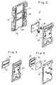
- the distance window 5 contains according to Figure 2 next to that area to be exposed of the individual film images of the motion picture film determining picture window 52 one of the back of the Motion picture film facing pressure plate 7a, the pressure plate 7a pressure piece 8a pressing against the motion picture film and lateral film guide walls 53, 54 with grooves and recesses 55 for receiving the gripper tips with the Film transport motor connected transport and locking gripper.
- the spacing window 5 ensures that the motion picture film 6 in a fixed focusing plane behind the image window 52 is moved so that a constant backing between the image plane and the attachment of the camera lens is guaranteed. This is due to the pressure plate 7a and the pressure piece 8a, which via compression springs 91, 92 are interconnected so that the pressure plate 7a with constant pressure on the back layer of the motion picture film is pressed.
- the pressure piece 8a itself is in not shown with a pivot mechanism connected, which is formed as part of the film transport module is.
- the pressure plate 7a is a full-surface plate formed according to the invention from black, non-reflective or light absorbing material or one appropriate coating or coloring.
- Figure 3 shows a pressure plate 7b with a transverse to Slide guide 77 extending from Sigradur K. Glassy carbon, which is configured using one of the Slide web 77 adapted pressure piece 8b on the back layer of a motion picture film.
- Figure 4 shows a pressure plate 7c with two parallel to each other and transverse to the film guide direction Slideways 78, 79 made of Sigradur K. glass charcoal, over a Intermediate plate 7d and three holes and corresponding ones Connecting screws are connected to a pressure piece 8c and pressed against the back layer of a motion picture film become.
- pressure plate 7 consists of a pressure piece 71, a holder 72, a handle 73 and several, in the present embodiment five, facing the back of the motion picture film, elongated, arranged parallel to each other and in the transport or film guide direction of the motion picture film 6 extending sliding webs 74, which according to Figure 6 in depressions 76 of the bracket 72 inserted and with the bracket 72 are glued, preferably with a two-component adhesive.
- the sliding webs 74 consist of Sigradur K. glass carbon, whereby the flattened ones at the back of the film Surfaces 75 of the sliding webs 74 are ground and / or are polished to further reduce the friction of the on the slide webs 74 along sliding motion picture film 6 achieve.
- the pressure plate 7 consists of a radiation-absorbing or non-reflective material or the slide bars 74 receiving surface 70 of the pressure plate 7 covered with a dark, preferably black material, for example painted with a corresponding color. It is also within the scope of the present invention that the entire distance window 5, i.e. the picture window, the side webs and the pressure plate 7 from one radiation absorbing or non-reflecting material consists.
- the radiation absorbing surface 70 of the pressure plate 7 in connection with the Sigradur K. glass coal Sliding bars 74 prevent reflection of the exposure rays at the distance window 5 and thus a corresponding falsification the image content of the individual images of the motion picture film 6th
- the sliding webs 74 are in accordance with Figure 7 provided with slopes 11, 12, and additional Radii at the ends of the sliding webs 74 ensure low friction Guide of motion picture film 6 as well as for a gentle one Guide of the motion picture film 6. In addition Reflections on the edges of the sliding webs 74 avoided.
- the holder 72 is partially undercut so that an elastic system of Bracket 72 on the pressure piece 71 is given.
Landscapes
- Physics & Mathematics (AREA)
- General Physics & Mathematics (AREA)
- Registering, Tensioning, Guiding Webs, And Rollers Therefor (AREA)
- Studio Devices (AREA)
- Endoscopes (AREA)
- Projection-Type Copiers In General (AREA)
- Feeding Of Articles By Means Other Than Belts Or Rollers (AREA)
Description
- Figur 1 -
- eine Seitenansicht eines Kameragehäuses einer Laufbildkamera mit geöffneter Kameratür und einer auf das Kameragehäuse aufgesetzten Filmkassette;
- Figur 2 -
- eine perspektivische Sprengzeichnung eines Abstandsfensters mit Filmführung und vollflächiger Andruckplatte;
- Figur 3 -
- eine perspektivische Sprengzeichnung mit einer Andruckplatte mit einem quer zur Filmführungsrichtung angeordneten Gleitsteg;
- Figur 4 -
- eine perspektivische Sprengzeichnung mit einer Andruckplatte mit zwei quer zur Filmführungsrichtung angeordneten Gleitstegen;
- Figur 5 -
- eine Rückseitenansicht einer Andruckplatte;
- Figur 6 -
- eine teilweise geschnittene Draufsicht auf die Andruckplatte gemäß Figur 5 mit fünf in Filmführungsrichtung angeordneten Gleitstegen;
- Figur 7 -
- eine Vorderseitenansicht der Andruckplatte gemäß den Figuren 5 und 6;
- Figur 8-
- einen Schnitt durch die Andruckplatte gemäß Figur 7 entlang der Linie A-A;
- Figur 9 -
- eine vergrößerte Darstellung des Bereichs X einer Gleitstegaufnahme der Andruckplatte gemäß Figur 8 und
- Figur 10 -
- einen Schnitt durch die Andruckplatte gemäß Figur 7 entlang der Linie B-B;
Claims (11)
- Filmführung für eine Laufbildkamera mit einem im Aufnahmestrahlengang (3) der Laufbildkamera angeordneten Abstandsfenster (5), das ein Bildfenster (52) und eine Andruckplatte (7) aufweist, zwischen denen der Laufbildfilm (6) bewegt wird, wobei zumindest die dem Laufbildfilm (6) zugewandte Oberfläche der Andruckplatte (7) strahlenabsorbierend oder nichtreflektierend ist,
dadurch gekennzeichnet, daß die Andruckplatte (7) aus einem durchgehend schwarzen Material besteht und mindestens einen in Filmführungsrichtung, quer oder diagonal zur Filmführungsrichtung angeordneten Gleitsteg (74, 77-79) aus Glaskohle aufweist. - Filmführung nach Anspruch 1, dadurch gekennzeichnet, daß die Andruckplatte (7) zumindest teilweise aus Glaskohle besteht.
- Filmführung nach Anspruch 1 oder 2, dadurch gekennzeichnet, daß die Andruckplatte (7) oder die Gleitstege (74, 77-79) aus Sigradur® K-Glaskohle besteht/bestehen.
- Filmführung nach Anspruch 1, dadurch gekennzeichnet, daß die Andruckplatte (7) parallel zueinander angeordnete Gleitstege (74, 78, 79) aus Glaskohle aufweist.
- Filmführung nach einem der vorangehenden Ansprüche, dadurch gekennzeichnet, dass der/die Gleitstege (74, 77-79) auf die Andruckplatte (7) aufgeklebt ist/sind.
- Filmführung nach einem der vorangehenden Ansprüche, dadurch gekennzeichnet, daß die Gleitstege (74, 77-79) in länglichen, in Filmtransportrichtung verlaufenden Vertiefungen (76) der Andruckplatte (7) angeordnet sind.
- Filmführung nach einem der vorangehenden Ansprüche, dadurch gekennzeichnet, daß die Gleitstege (74, 77-79) an ihren Enden abgeschrägt sind.
- Filmführung nach einem der vorangehenden Ansprüche, dadurch gekennzeichnet, daß die Gleitstege (74, 77-79) geschliffen und/oder poliert sind.
- Filmführung nach einem der Ansprüche 1 bis 3, dadurch gekennzeichnet, daß die Andruckplatte (7) in der Ebene senkrecht zur Laufbildfilmebene zumindest teilweise elastisch ausgebildet ist.
- Filmführung nach einem der Ansprüche 1 bis 3, dadurch gekennzeichnet, daß die Andruckplatte (7) rastend in das Abstandsfenster (5) einsetzbar ist.
- Filmführung nach einem Ansprüche 1 bis 3, dadurch gekennzeichnet, daß das Abstandsfenster (5) vorzugsweise gelenkig und trennbar mit einem Antriebsmodul (4) der Laufbildkamera (1) verbunden ist.
Applications Claiming Priority (2)
| Application Number | Priority Date | Filing Date | Title |
|---|---|---|---|
| DE19860712A DE19860712A1 (de) | 1998-12-23 | 1998-12-23 | Filmführung für eine Laufbildkamera |
| DE19860712 | 1998-12-23 |
Publications (2)
| Publication Number | Publication Date |
|---|---|
| EP1014163A1 EP1014163A1 (de) | 2000-06-28 |
| EP1014163B1 true EP1014163B1 (de) | 2003-02-12 |
Family
ID=7893118
Family Applications (1)
| Application Number | Title | Priority Date | Filing Date |
|---|---|---|---|
| EP99250444A Expired - Lifetime EP1014163B1 (de) | 1998-12-23 | 1999-12-22 | Filmführung für eine Laufbildkamera |
Country Status (4)
| Country | Link |
|---|---|
| US (1) | US6457827B1 (de) |
| EP (1) | EP1014163B1 (de) |
| AT (1) | ATE232610T1 (de) |
| DE (2) | DE19860712A1 (de) |
Families Citing this family (5)
| Publication number | Priority date | Publication date | Assignee | Title |
|---|---|---|---|---|
| US6742896B2 (en) * | 2001-05-15 | 2004-06-01 | Disney Enterprises, Inc. | Film trap and gate assembly for a motion picture projector |
| US7189259B2 (en) | 2002-11-26 | 2007-03-13 | Clemson University | Tissue material and process for bioprosthesis |
| US7393105B2 (en) * | 2004-02-04 | 2008-07-01 | Arnold & Richter Cine Technik Gmbh & Co. Betriebs Kg | Film guide for a movie camera |
| DE502004008553D1 (de) * | 2004-02-04 | 2009-01-08 | Arnold & Richter Kg | Filmführung für eine laufbildkamera |
| USD1008344S1 (en) * | 2021-07-30 | 2023-12-19 | Arnold & Richter Cine Technik Gmbh & Co. Betriebs Kg | Mount for camera or camera accessory |
Family Cites Families (14)
| Publication number | Priority date | Publication date | Assignee | Title |
|---|---|---|---|---|
| US1404707A (en) * | 1919-11-24 | 1922-01-24 | Silent Drama Syndicate | Film gate for kinetograph mechanism |
| US3103861A (en) * | 1958-12-19 | 1963-09-17 | Adox Kamerawerk G M B H | Pressure plate assembly for cameras or magazines |
| US3479114A (en) * | 1967-12-28 | 1969-11-18 | Technical Operations Inc | Intermittent film contact pressure apparatus for cinematographic cameras |
| US3833292A (en) | 1971-03-25 | 1974-09-03 | O Blaschek | Motion picture camera comprising an externally attached detachable cassette |
| US3954330A (en) * | 1971-11-17 | 1976-05-04 | Canon Kabushiki Kaisha | Film gate unit for motion picture apparatus |
| DE2218793A1 (de) * | 1972-04-18 | 1973-10-31 | Braun Ag | Filmfuehrung in filmgeraeten |
| US3912381A (en) * | 1973-12-26 | 1975-10-14 | Polaroid Corp | Photographic apparatus and method for locating film in a precise focal plane |
| JPS58163939U (ja) * | 1982-04-28 | 1983-11-01 | 富士写真フイルム株式会社 | フイルム圧板 |
| US4522476A (en) * | 1984-06-25 | 1985-06-11 | Walter Renold | Motion picture film gate and registration system |
| JPS6127527A (ja) * | 1984-07-17 | 1986-02-07 | Canon Inc | カメラの圧着板 |
| DE8531946U1 (de) * | 1985-11-12 | 1986-01-16 | Arnold & Richter Cine Technik GmbH & Co Betriebs KG, 8000 München | Laufbild-Filmaufnahmekamera |
| FR2594965B1 (fr) * | 1986-02-24 | 1988-09-16 | Aaton Rgo | Dispositif de guidage d'un film dans une camera cinematographique |
| DE4013909A1 (de) * | 1990-04-26 | 1991-10-31 | Arnold & Richter Kg | Bildfenster fuer laufbildkameras |
| JPH04362621A (ja) * | 1991-06-11 | 1992-12-15 | Kyocera Corp | セラミック製カメラ用圧板 |
-
1998
- 1998-12-23 DE DE19860712A patent/DE19860712A1/de not_active Withdrawn
-
1999
- 1999-12-22 DE DE59904270T patent/DE59904270D1/de not_active Expired - Lifetime
- 1999-12-22 AT AT99250444T patent/ATE232610T1/de not_active IP Right Cessation
- 1999-12-22 US US09/470,932 patent/US6457827B1/en not_active Expired - Fee Related
- 1999-12-22 EP EP99250444A patent/EP1014163B1/de not_active Expired - Lifetime
Also Published As
| Publication number | Publication date |
|---|---|
| US6457827B1 (en) | 2002-10-01 |
| ATE232610T1 (de) | 2003-02-15 |
| US20020021413A1 (en) | 2002-02-21 |
| DE19860712A1 (de) | 2000-07-13 |
| EP1014163A1 (de) | 2000-06-28 |
| DE59904270D1 (de) | 2003-03-20 |
Similar Documents
| Publication | Publication Date | Title |
|---|---|---|
| DE2736486C3 (de) | Optische Vorrichtung zur Aufzeichnung und zum Auslesen von Mikroinformation | |
| DE3889297T2 (de) | Ebene Lichtquelle. | |
| CH627557A5 (de) | Optisches element zur sammlung, fuehrung und auskopplung von strahlung. | |
| DE102005018091A1 (de) | Bildwand des Reflexionstyps | |
| EP2388145A1 (de) | Umlenkspiegeleinheit und Vorrichtung zur Laserbeschriftung mit einer solchen Umlenkeinheit | |
| DE2804704A1 (de) | Projektionseinrichtung | |
| EP1014163A1 (de) | Filmführung für eine Laufbildkamera | |
| DE2651720B2 (de) | Optisches Suchersystem für eine Spiegelreflexkamera | |
| DE2048414B2 (de) | Vorrichtung zur fotoelektrischen abtastung | |
| DE4013909A1 (de) | Bildfenster fuer laufbildkameras | |
| DE2810282C2 (de) | Mikrofilmeinrichtung zur Informationssicherung bei der automatischen Belegverarbeitung | |
| DE2004640C3 (de) | Filmstreifenhalter für ein audiovisuelles Gerät | |
| DE8304588U1 (de) | Vorrichtung zur inspektion von schreib-lese-koepfen von datentraegerplatten in edv-anlagen | |
| EP0021308A1 (de) | Anordnung zur Helligkeitsverstärkung von passiven Anzeigevorrichtungen | |
| DE2042229B2 (de) | Mehrstufige, steuerbare Lichtstrahlablenkvorrichtung | |
| DE2652778B2 (de) | Vorrichtung zum beobachten eines magnetbandes in einer in ein tonbandgeraet eingelegten kassette | |
| DE2932389C2 (de) | Photoelektrische Positionsmeßeinrichtung | |
| DE2738658B2 (de) | Mikrobildprojektor | |
| DE68924742T2 (de) | Linsenanordnungen für Auflichtprojektionsschirme sowie Verfahren und Vorrichtung zur Kontrastverbesserung. | |
| DE2504913C3 (de) | Vorrichtung zum Betrachten von Schmalfilmen | |
| DE19756567B4 (de) | Prisma | |
| DE2608789A1 (de) | Kopplung fuer lichtleitfasern | |
| DE69701784T2 (de) | Bildabtastgerät | |
| DE29623287U1 (de) | Prisma für eine Daten-Cartridge | |
| DE3626632A1 (de) | Halterung fuer filmbilder |
Legal Events
| Date | Code | Title | Description |
|---|---|---|---|
| PUAI | Public reference made under article 153(3) epc to a published international application that has entered the european phase |
Free format text: ORIGINAL CODE: 0009012 |
|
| AK | Designated contracting states |
Kind code of ref document: A1 Designated state(s): AT DE FR GB IT |
|
| AX | Request for extension of the european patent |
Free format text: AL;LT;LV;MK;RO;SI |
|
| 17P | Request for examination filed |
Effective date: 20001207 |
|
| AKX | Designation fees paid |
Free format text: AT DE FR GB IT |
|
| 17Q | First examination report despatched |
Effective date: 20011105 |
|
| GRAG | Despatch of communication of intention to grant |
Free format text: ORIGINAL CODE: EPIDOS AGRA |
|
| GRAG | Despatch of communication of intention to grant |
Free format text: ORIGINAL CODE: EPIDOS AGRA |
|
| GRAH | Despatch of communication of intention to grant a patent |
Free format text: ORIGINAL CODE: EPIDOS IGRA |
|
| GRAH | Despatch of communication of intention to grant a patent |
Free format text: ORIGINAL CODE: EPIDOS IGRA |
|
| GRAA | (expected) grant |
Free format text: ORIGINAL CODE: 0009210 |
|
| AK | Designated contracting states |
Designated state(s): AT DE FR GB IT |
|
| PG25 | Lapsed in a contracting state [announced via postgrant information from national office to epo] |
Ref country code: IT Free format text: LAPSE BECAUSE OF FAILURE TO SUBMIT A TRANSLATION OF THE DESCRIPTION OR TO PAY THE FEE WITHIN THE PRESCRIBED TIME-LIMIT;WARNING: LAPSES OF ITALIAN PATENTS WITH EFFECTIVE DATE BEFORE 2007 MAY HAVE OCCURRED AT ANY TIME BEFORE 2007. THE CORRECT EFFECTIVE DATE MAY BE DIFFERENT FROM THE ONE RECORDED. Effective date: 20030212 Ref country code: FR Free format text: LAPSE BECAUSE OF FAILURE TO SUBMIT A TRANSLATION OF THE DESCRIPTION OR TO PAY THE FEE WITHIN THE PRESCRIBED TIME-LIMIT Effective date: 20030212 |
|
| REG | Reference to a national code |
Ref country code: GB Ref legal event code: FG4D Free format text: NOT ENGLISH |
|
| REF | Corresponds to: |
Ref document number: 59904270 Country of ref document: DE Date of ref document: 20030320 Kind code of ref document: P |
|
| GBT | Gb: translation of ep patent filed (gb section 77(6)(a)/1977) |
Effective date: 20030514 |
|
| PLBE | No opposition filed within time limit |
Free format text: ORIGINAL CODE: 0009261 |
|
| STAA | Information on the status of an ep patent application or granted ep patent |
Free format text: STATUS: NO OPPOSITION FILED WITHIN TIME LIMIT |
|
| PG25 | Lapsed in a contracting state [announced via postgrant information from national office to epo] |
Ref country code: AT Free format text: LAPSE BECAUSE OF NON-PAYMENT OF DUE FEES Effective date: 20031222 |
|
| EN | Fr: translation not filed | ||
| 26N | No opposition filed |
Effective date: 20031113 |
|
| PGFP | Annual fee paid to national office [announced via postgrant information from national office to epo] |
Ref country code: GB Payment date: 20131217 Year of fee payment: 15 Ref country code: DE Payment date: 20131211 Year of fee payment: 15 |
|
| REG | Reference to a national code |
Ref country code: DE Ref legal event code: R119 Ref document number: 59904270 Country of ref document: DE |
|
| GBPC | Gb: european patent ceased through non-payment of renewal fee |
Effective date: 20141222 |
|
| PG25 | Lapsed in a contracting state [announced via postgrant information from national office to epo] |
Ref country code: DE Free format text: LAPSE BECAUSE OF NON-PAYMENT OF DUE FEES Effective date: 20150701 Ref country code: GB Free format text: LAPSE BECAUSE OF NON-PAYMENT OF DUE FEES Effective date: 20141222 |