EP1014010A2 - Klimaanlage - Google Patents
Klimaanlage Download PDFInfo
- Publication number
- EP1014010A2 EP1014010A2 EP99310588A EP99310588A EP1014010A2 EP 1014010 A2 EP1014010 A2 EP 1014010A2 EP 99310588 A EP99310588 A EP 99310588A EP 99310588 A EP99310588 A EP 99310588A EP 1014010 A2 EP1014010 A2 EP 1014010A2
- Authority
- EP
- European Patent Office
- Prior art keywords
- front panel
- intake grille
- air conditioner
- engaging
- display component
- Prior art date
- Legal status (The legal status is an assumption and is not a legal conclusion. Google has not performed a legal analysis and makes no representation as to the accuracy of the status listed.)
- Granted
Links
Images
Classifications
-
- F—MECHANICAL ENGINEERING; LIGHTING; HEATING; WEAPONS; BLASTING
- F24—HEATING; RANGES; VENTILATING
- F24F—AIR-CONDITIONING; AIR-HUMIDIFICATION; VENTILATION; USE OF AIR CURRENTS FOR SCREENING
- F24F1/00—Room units for air-conditioning, e.g. separate or self-contained units or units receiving primary air from a central station
- F24F1/0007—Indoor units, e.g. fan coil units
- F24F1/0059—Indoor units, e.g. fan coil units characterised by heat exchangers
- F24F1/0063—Indoor units, e.g. fan coil units characterised by heat exchangers by the mounting or arrangement of the heat exchangers
-
- F—MECHANICAL ENGINEERING; LIGHTING; HEATING; WEAPONS; BLASTING
- F24—HEATING; RANGES; VENTILATING
- F24F—AIR-CONDITIONING; AIR-HUMIDIFICATION; VENTILATION; USE OF AIR CURRENTS FOR SCREENING
- F24F11/00—Control or safety arrangements
- F24F11/30—Control or safety arrangements for purposes related to the operation of the system, e.g. for safety or monitoring
-
- F—MECHANICAL ENGINEERING; LIGHTING; HEATING; WEAPONS; BLASTING
- F24—HEATING; RANGES; VENTILATING
- F24F—AIR-CONDITIONING; AIR-HUMIDIFICATION; VENTILATION; USE OF AIR CURRENTS FOR SCREENING
- F24F11/00—Control or safety arrangements
- F24F11/50—Control or safety arrangements characterised by user interfaces or communication
- F24F11/52—Indication arrangements, e.g. displays
-
- F—MECHANICAL ENGINEERING; LIGHTING; HEATING; WEAPONS; BLASTING
- F24—HEATING; RANGES; VENTILATING
- F24F—AIR-CONDITIONING; AIR-HUMIDIFICATION; VENTILATION; USE OF AIR CURRENTS FOR SCREENING
- F24F13/00—Details common to, or for air-conditioning, air-humidification, ventilation or use of air currents for screening
- F24F13/20—Casings or covers
- F24F2013/207—Casings or covers with control knobs; Mounting controlling members or control units therein
Definitions
- the present invention relates to structures of a front panel with an intake grille, which can be opened and closed, and of display components attached to the front panel with the intake grille.
- Figure 16 illustrates a structure of attaching display components in a conventional air conditioner disclosed in, for example, Japanese Unexamined Patent Publication JP-A-9-4869.
- Numerical reference 1 designates a body of the air conditioner;
- numerical reference 20 designates the display components,
- numerical reference 4 designates a front panel with an intake grille;
- numerical reference 16 designates a design panel;
- numerical reference 17 designates a display board; and
- numerical reference 18 designates a holder of the display board.
- the display board 17 is fixed to the body 1 of the air conditioner by the holder 18.
- the display components 4 is fixed to an inside of the design panel 16 by fusion bond, adhesion and so on or fixed to the inside of the design panel 16 so as to be pushed by the holder 18 toward the inside.
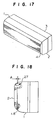
- Figure 17 is a perspective view illustrating an indoor unit of a conventional air conditioner disclosed in, for example, Japanese Unexamined Patent Publication JP-A-4-50325.
- Figure 18 is a side view of a panel opening and closing device of the conventional air conditioner partly broken, and
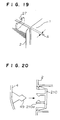
- Figure 19 is an enlarged view of an important portion of the panel opening and closing device of the conventional air conditioner.
- numerical reference 1 designates a body of an indoor unit of the air conditioner
- numerical reference 2 designates a front casing of the indoor unit
- numerical reference 4 designates a front panel covering a front side of the front casing, the front panel can be opened and closed
- numerical reference 3 designates a back casing of the indoor unit, wherein the body 1 of the indoor unit is constructed by the back casing 3, the front casing 2 and the front panel 4.
- numerical reference 49 designates an engaging claw provided in the engaging portions 48 of the front panel 4;
- numerical reference 210 designates an engaging part integrally formed with an arm 210a.
- the front panel 4 is connected to the front casing 2 by the shafts 27 so as to be opened and closed by a rotation with center at the shaft 27.
- the lower portion of the front panel 4 is engaged by the plurality of engaging portions provided on left and right sides or in a center of the front casing 2.
- the body 1 of the indoor unit is constructed by the back casing 3, the front casing 2 and the front panel 4.
- the engaging part 210 in the front panel is fixed to the front casing 2 by the engaging claws 49 formed in the front casing 2.
- the front panel 4 rotates around the shafts 27 so as to be opened and closed in a forward direction of the front casing 2.
- the front panel 4 When the front panel 4 is closed, it is engaged such that a tip of the engaging claw 49 in the front panel 4 exceeds tips of the arm 210a in the engaging part 210, the arms 210a are elastically deformed to open and close, and the tip of the engaging claw 49 is interposed between the arms 210a.
- a gap A is formed as illustrated in Figure 19 to deteriorate a look, wherein the gap A is formed in an upper mating surface between the front casing and the front panel by a warp occurred in molding the front panel when a distance between the shaft being a connecting portion and an end surface or between the shafts is long in an upper portion of the front panel because the lower portion of the front panel is engaged at a plurality of positions and the upper portion of the front panel is supported by the shafts at time of closing the front panel.
- the arms of the engaging part are spreaded and closed, whereby stress caused by spreading and closing is concentrated on the arms.
- Another object of the present invention is to provide a structure of securely attaching the display components without a positional deviation when the display components are attached to the front panel with the intake grille.
- Another object of the present invention is to obtain a device for holding the front panel with the intake grille used when the front panel is closed, the device for holding can prevent deterioration of a look.
- Another object of the present invention is to relax concentration of stress on engaging parts and also to minimize an influence by a positional deviation between an engaging claw of the front panel and an engaging part fixed to the front casing.
- an air conditioner comprising a body of the air conditioner, an LED for displaying a running condition and so on of the air conditioner by a light, the LED is provided in an inside of the body, a front casing provided on a front side of the body, a flexible display component having a recess, the flexible display component aesthetically formed diffuses the light from the LED, an opening portion provided in the front casing so as to be opened and closed, to which opening portion both ends of the display component are inserted to engage therewith, and a front panel with an intake grille having a protrusion engaged with the recess of the display component, whereby the both ends of the display component is curved and inserted in the opening portion of the front panel with the intake grille.
- the air conditioner wherein at least one of recesses of the display component and the protrusion of the front panel with the intake grille has a guiding slanted portion.
- the air conditioner wherein the front panel with the intake grille has an engaging protrusion and an engaging opening, and a design cover having an engaging opening engaged with the engaging protrusion of the front panel with the intake grille, an engaging piece engaged with the engaging opening of the front panel with the intake grille and a display opening engaged with the display component, wherein the design cover is attached to the front panel with the intake grille such that the display component is interposed between the front panel with the intake grille and the design cover.
- the air conditioner including a structure of opening and closing the front panel with the intake grille constructed such that at least one float stopper is provided in the vicinity of left and right end portions of the front panel with the intake grille, which is provided in the body of the air conditioner so as to be opened and closed with center at an axis, or is provided on a center of an inside center of the front panel with the intake grille, and a receiving portion formed in the front casing.
- the air conditioner including a structure of opening and closing the front panel having at least one stopper formed in a wedge shape with respect to an orbit with the center at the axis at time of opening and closing the front panel provided in the vicinity of left and right end surfaces of the front panel with the intake grille, which is opened and closed, or at a center of an inside of the front panel with the intake grille, and a receiving portion provided in the front panel with the intake grille.
- the air conditioner including a structure of opening and closing the front panel with the intake grille having an engaging claw provided in the front panel with the intake grille of the body of the air conditioner, and an engaging part having an arm provided in the front casing, wherein the arm of the engaging claw is attached so as to have spaces from the engaging claw in a direction of spreading the arms.
- the air conditioner including the structure of opening and closing the front panel with the intake grille, wherein a pair of arms are provided in the engaging part, and a triangle thick portion is provided in the engaging claw so as to be a supporting point against a deviation, and an intermediate portion of the engaging claw is thin.
- the air conditioner including the structure of opening and closing the front panel with the intake grille having a rail slidably provided in the spreading directions of the arms or an adjusting rib provided in directions perpendicular to the spreading directions of the arms for adjusting the spaces in the perpendicular directions.
- the air conditioner including the structure of opening and closing the front panel with the intake grille having at least one float stopper for the front panel with the intake grille, which is opened and closed with center at an axis, provided in the vicinity of left and right end surfaces of the front panel with the intake grille at a center of an inside of the front panel with the intake grille, an engaging claw provided in the front panel with the intake grille, and an engaging part having an arm provided in the front casing, wherein the engaging claw is attached so as to have a play in a spreading direction of the arm of the engaging part.
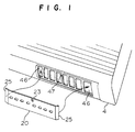
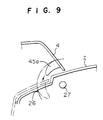
- Figure 1 is a perspective view of an important portion of an air conditioner
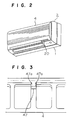
- Figure 2 is a perspective view of the air conditioner.
- numerical reference 1 designates a body of the air conditioner, in which a plurality of LEDs for displaying a running condition and so on by a light, is provided
- numerical reference 20 designates a display component having a recess 23 at a center of an upper portion, the display component aesthetically formed diffuses the light of the LEDs.
- Numerical reference 4 designates a front panel with an intake grille having an opening portion 46 for inserting both ends 25 of the display component 20 for engaging therewith and a protrusion 47 engaged with the recess 23 of the display component 2.
- the display component 20 is deflected and the both ends thereof are inserted in the opening portion 46 of the front panel with the intake grille 4. Thereafter, the deflection is canceled. At this time, the recess 23 of the display component 2 is engaged with the protrusion 47 of the front panel with the intake grille 4, and simultaneously the display component 20 is engaged with the opening portion 46 of the front panel with the intake grille 4, whereby an attachment of the display component 20 to the front panel with the intake grille 4 is completed.
- Embodiment 1 by deflecting the display component 20, the both ends are easily inserted in the opening portion 46 of the front panel with the intake grille 4. And further, the display component 20 is attached to the front panel with the intake grille 4 without a positional deviation since the recess 23 of the display component 20 is engaged with the protrusion 47 of the front panel with the intake grille.
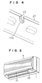
- Figures 3 and 4 are perspective views of an important portion of an air conditioner for explaining Embodiment 2 of the present invention.
- numerical reference 23a designates a guiding slanted portion provided in a recess 23 of a display component
- numerical reference 47 designate a guiding slanted portion provided in a protrusion 47 of a front panel with an intake grille 4.
- Both ends 25 of the display component 20 are inserted in an opening portion 46 of the front panel with the intake grille 4 after deflecting the display component 20, and thereafter the deflection of the display component 20 is canceled.
- the protrusion 47 is in contact with the guiding slanted portion 23a provided in the recess 23 of the display component 20, or the recess 23 of the display component 20 is in contact with the guiding slanted portion 47 provided in the protrusion 47 of the front panel with the intake grille 4, whereby the protrusion 47 of the front panel with the intake grille 4 is easily engaged with the recess 23 of the display component 20.
- an attachment of the display component 20 to the front panel with the intake grille is completed.
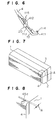
- Figures 5 and 6 explains Embodiment 3 of the present invention.
- Figure 5 is a perspective view of an air conditioner.
- Figure 6 is a perspective view of an important portion of the air conditioner.
- numerical references 411, 412 respectively designate an engaging protrusion and an engaging holl, both provided in a front panel with an intake grille.
- Numerical reference 10 designates a design cover having a display opening 113, and an engaging opening 114 and engaging piece 115 which are engaged with the engaging protrusion 411 and the engaging opening 412.
- Embodiments 4 through 8 a preferable structure of opening and closing the front panel and that provided with the design cover according to Embodiments 1, 2 and 3 will be described.
- numerical reference 1 designates a body of an indoor unit of an air conditioner
- numerical reference 2 designates a front casing of the indoor unit
- numerical reference 4 designates a front panel for covering a front of the front casing, the front panel is opened and closed
- numerical reference 3 designates a back casing of the indoor unit.
- the body of the indoor unit is constructed by the back casing 3, the front casing 2 and the front panel 4.
- Numerical reference 45a designates a stopper in a wedge-like shape with respect to a circle with center at an axis center of the front panel 4, which is provided in the vicinity of left and right end surfaces of the front panel 4 or at a center of an inside of the front panel 4.
- Numerical reference 26 designates a receiving portion provided in the front casing 2; and numerical reference 27 designates a shaft as the axis center of opening and closing the front panel 4.
- Embodiment 4 An operation of Embodiment 4 will be described. As illustrated in Figure 9, when the front panel 4 is closed, the stopper 45a of the front panel 4 traces a rotation locus with center at the shaft 27 and thereafter is engaged with the receiving portion 26 of the front casing. Since the stopper 45a of the front panel 4 is in the wedge-like shape with respect to the rotation locus with center at the shaft 27, the front panel 4 is pulled toward the front casing 2 even though the front panel 4 is warped.
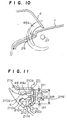
- Figure 10 illustrates a structure of opening and closing a front panel of an air conditioner according to Embodiment 5 of the present invention.
- a stopper 45b of the front panel 4 is longer than the stopper described in Embodiment 1. Therefore, the stopper 45b of the front panel 4 is engaged with a receiving portion 26 of a front casing 2 when the front panel 4 is opened.
- the front panel 4 does not leftward and rightward shift as long as the stopper 5b of the front panel 4 is engaged with the receiving portion 26 of the front casing 2 since the stopper 45b is long toward rotation directions of the front panel 4.
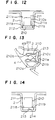
- Figure 11 is a side cross-sectional view of an important portion of a device for opening and closing a front panel of an air conditioner according to Embodiment 6 of the present invention.
- Figure 12 is a plan cross-sectional view of the important portion.
- numerical reference 4 designates a front panel which is opened and closed;
- numerical reference 49 designates an engaging claw provided in a lower portion of the front panel, the engaging claw forms an arrow-like tip 49a protruding toward and inside of the front panel.
- Numerical reference 210 designates engaging parts having a pair of arms 210a for securing the engaging claw 49 of the front panel, the engaging part is formed by the arms having a triangular piece 210b directed in a securing direction at its top end so as to hold the arrow-like tip 49a of the engaging claw 49 and a base 210c for supporting the arms at the other end thereof.
- the base has a tin portion 210d at a center on the side other than that of the arms 210a and triangular thick portions 210e at around the thin portion.
- Numerical reference 211 designates an engaging housing having a width 500 for accommodating these engaging parts, the engaging housing is formed in a lower portion of the front casing 2.
- a holding claw 211b is protruded at an intermediate position of the vertical width 500 of a side wall 211a, and the engaging part 210 is held with gaps 501 from upper and lower walls 211c.
- Numerical reference 212 designates an adjusting rib provided on a bottom side of the side walls 211a in the engaging housing 211.
- Embodiment 6 When the front panel 4 is closed, the engaging claw 49 is inserted between the arms 210a of the engaging part 210.
- the arrow-like tip 49a of the engaging claw 49 is inserted along the triangular pieces 210b at the tips of the arms while being in contact therewith so that the engaging claw 9 is fixed in alignment with a substantially center of the engaging part 210.
- front casing 2 and the engaging part 210 are separate components, it is possible to omit a fractionating work in recycling in use of a same resin material for the front casing 2 and the engaging part 210.
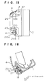
- Figure 13 is a side cross-sectional view of an important portion of a device for opening and closing a front panel of an air conditioner according to Embodiment 7 of the present invention.
- Figure 14 is a plan cross-sectional view of the important portion.
- numerical reference 213 designates a rib provided substantially at a center of a front wall 211d of an engaging housing 11 on a longitudinal direction of the engaging housing 211.
- Numerical reference 214 designates a groove provided in a base 210a of an engaging part 210 in the longitudinal direction so as to be engaged with the rib.
- the engaging part 210 is arranged substantially at the center of the engaging housing 211 without leftward and rightward deviating.
- Figure 15 is a side view of a device for opening and closing a front panel of an air conditioner partly broken for showing cross-sections according to Embodiment 8 of the present invention.
- a stopper 45 is engaged with a receiving portion 26 of the front casing 2 at a wedge-like portion, and simultaneously an arrow-like tip 49a of an engaging claw 49 is inserted in an engaging part 210 along triangular claws 210b at tips of arms 210a while being in contact with the triangular claws 210b.
- the engaging claw 49 is securely held by the arms 210a even though upward and downward positional deviations occur between the engaging part 210 and the front panel 4 because the positional deviation is managed by gaps 501.
- Figure 15 illustrates a case that structures described in Embodiments 4, 5, 6 and 7 are simultaneously used, whereby a leftward and rightward deviation and an upward and downward deviation of the front casing 2 are managed in positioning the front panel 4 at time of opening and closing the front panel 4.
- the first advantage of the air conditioner according to the present invention is that the display component can be easily attached to the front panel with the intake grille without a positional deviation at a low cost.
- the second advantage of the air conditioner according to the present invention is that the display component is securely attached to the front panel with the intake grille.
- the third advantage of the air conditioner according to the present invention is that the parts made of different materials can be easily disassembled and demolished.
- the fourth advantage of the air conditioner according to the present invention is that it is possible to prevent deterioration of an outer look of the air conditioner because the front panel is drawn on a side of the front casing so that a gap between the front panel and the front casing is constantly maintained.
- the fifth advantage of the air conditioner according to the present invention is that a scattering of a deviation of a load to the engaging part and of engaging force at time of opening and closing the front panel is suppressed even though a positional deviation between the engaging claw of the front panel and the engaging part fixed to the front casing occurs.
- the seventh advantage of the air conditioner according to the present invention is that a scattering of engaging force by a deviation of a load to the engaging part can be suppressed even though a positional deviation occurs between the engaging claw of the front panel and the engaging part fixed to the front casing.
- the seventh advantage of the air conditioner according to the present invention is that a scattering of a closed state of the front panel at time of opening and closing the front panel is reduced because the engaging claw pulls the engaging part toward a center of the engaging part by the gap provided in the attaching portion of the engaging part.
- the eighth advantage of the air conditioner according to the present invention is that upward and downward movements of the engaging part are smoothly realized without changing attaching directions of the engaging part, and a load in other than the opening and closing directions is not applied to the arms of the engaging part.
- the ninth advantage of the air conditioner according to the present invention is that the front panel is held with leftward and rightward deviations from the front casing being absorbed and with upward and downward deviations being absorbed at time of positioning the front panel in an opened state and a closed state.
Landscapes
- Engineering & Computer Science (AREA)
- Chemical & Material Sciences (AREA)
- Combustion & Propulsion (AREA)
- Mechanical Engineering (AREA)
- General Engineering & Computer Science (AREA)
- Human Computer Interaction (AREA)
- Physics & Mathematics (AREA)
- Thermal Sciences (AREA)
- Air Filters, Heat-Exchange Apparatuses, And Housings Of Air-Conditioning Units (AREA)
- Illuminated Signs And Luminous Advertising (AREA)
Applications Claiming Priority (4)
| Application Number | Priority Date | Filing Date | Title |
|---|---|---|---|
| JP36891998 | 1998-12-25 | ||
| JP36891998A JP3810227B2 (ja) | 1998-12-25 | 1998-12-25 | 空気調和機 |
| JP03246199A JP3835038B2 (ja) | 1999-02-10 | 1999-02-10 | 空気調和機のパネル開閉装置 |
| JP3246199 | 1999-02-10 |
Publications (3)
| Publication Number | Publication Date |
|---|---|
| EP1014010A2 true EP1014010A2 (de) | 2000-06-28 |
| EP1014010A3 EP1014010A3 (de) | 2002-04-10 |
| EP1014010B1 EP1014010B1 (de) | 2004-06-23 |
Family
ID=26371040
Family Applications (1)
| Application Number | Title | Priority Date | Filing Date |
|---|---|---|---|
| EP99310588A Expired - Lifetime EP1014010B1 (de) | 1998-12-25 | 1999-12-24 | Klimaanlage |
Country Status (4)
| Country | Link |
|---|---|
| US (1) | US6202426B1 (de) |
| EP (1) | EP1014010B1 (de) |
| AU (1) | AU756019B2 (de) |
| ES (1) | ES2223159T3 (de) |
Cited By (2)
| Publication number | Priority date | Publication date | Assignee | Title |
|---|---|---|---|---|
| CN101818936B (zh) * | 2009-02-27 | 2013-10-30 | 乐金电子(天津)电器有限公司 | 分体式空调室内机的前面板组件 |
| CN106288287A (zh) * | 2016-09-09 | 2017-01-04 | 珠海格力电器股份有限公司 | 壳体组件及具有其的空调器 |
Families Citing this family (3)
| Publication number | Priority date | Publication date | Assignee | Title |
|---|---|---|---|---|
| US6260374B1 (en) * | 2000-04-26 | 2001-07-17 | American Standard International Inc. | Easily installable field configurable air conditioning unit |
| BRPI0418649A (pt) * | 2004-04-20 | 2007-05-29 | Lg Electronics Inc | ar condicionado |
| WO2009041424A1 (ja) * | 2007-09-28 | 2009-04-02 | Toshiba Carrier Corporation | 空気調和機の室外機 |
Citations (2)
| Publication number | Priority date | Publication date | Assignee | Title |
|---|---|---|---|---|
| JPH0450325A (ja) | 1990-06-12 | 1992-02-19 | Vyzk Ustav Bavlnarsky | 短繊維紡績装置 |
| JPH094869A (ja) | 1995-06-20 | 1997-01-10 | Toshiba Corp | 空気調和機の室内ユニット |
Family Cites Families (14)
| Publication number | Priority date | Publication date | Assignee | Title |
|---|---|---|---|---|
| JPS6136102Y2 (de) * | 1981-02-10 | 1986-10-20 | ||
| US4404813A (en) * | 1981-04-20 | 1983-09-20 | Whirlpool Corporation | Door mounted electronic housing assembly for a refrigerator |
| JPS6357456A (ja) | 1986-08-28 | 1988-03-12 | Ricoh Co Ltd | 複写機等のジヤム制御方法 |
| US4966004A (en) * | 1989-11-06 | 1990-10-30 | Amana Refrigeration, Inc. | Electronic control mounting apparatus for refrigerator |
| JPH05171856A (ja) | 1991-12-20 | 1993-07-09 | Toshiba Corp | 空気調和機における吸込グリルのヒンジ装置 |
| US5495887A (en) * | 1993-05-21 | 1996-03-05 | Erie Manufacturing (Canada) Co. Limited | Temperature control system and controller therefor |
| KR970001271Y1 (ko) * | 1994-02-24 | 1997-02-22 | 엘지전자 주식회사 | 냉장고의 온도조절부 회전식 개폐장치 |
| JPH09196409A (ja) * | 1996-01-10 | 1997-07-31 | Daikin Ind Ltd | 空気調和機 |
| JP3386310B2 (ja) * | 1996-03-19 | 2003-03-17 | 株式会社富士通ゼネラル | 空気調和機の前面パネル |
| JPH1096530A (ja) * | 1996-09-20 | 1998-04-14 | Fujitsu General Ltd | 空気調和機 |
| IL123390A (en) * | 1997-04-03 | 2000-11-21 | Funai Electric Co | Air conditioning system |
| US6085538A (en) * | 1998-08-26 | 2000-07-11 | Carrier Corporation | Control box door/fairing for front grille of an air conditioner |
| US6022270A (en) * | 1998-08-26 | 2000-02-08 | Carrier Corporation | Air conditioner front grille with inserts for brand differentiation |
| US6009717A (en) * | 1998-08-26 | 2000-01-04 | Carrier Corporation | Control box for a room air conditioner |
-
1999
- 1999-12-23 AU AU65460/99A patent/AU756019B2/en not_active Ceased
- 1999-12-23 US US09/471,492 patent/US6202426B1/en not_active Expired - Fee Related
- 1999-12-24 ES ES99310588T patent/ES2223159T3/es not_active Expired - Lifetime
- 1999-12-24 EP EP99310588A patent/EP1014010B1/de not_active Expired - Lifetime
Patent Citations (2)
| Publication number | Priority date | Publication date | Assignee | Title |
|---|---|---|---|---|
| JPH0450325A (ja) | 1990-06-12 | 1992-02-19 | Vyzk Ustav Bavlnarsky | 短繊維紡績装置 |
| JPH094869A (ja) | 1995-06-20 | 1997-01-10 | Toshiba Corp | 空気調和機の室内ユニット |
Cited By (2)
| Publication number | Priority date | Publication date | Assignee | Title |
|---|---|---|---|---|
| CN101818936B (zh) * | 2009-02-27 | 2013-10-30 | 乐金电子(天津)电器有限公司 | 分体式空调室内机的前面板组件 |
| CN106288287A (zh) * | 2016-09-09 | 2017-01-04 | 珠海格力电器股份有限公司 | 壳体组件及具有其的空调器 |
Also Published As
| Publication number | Publication date |
|---|---|
| US6202426B1 (en) | 2001-03-20 |
| EP1014010A3 (de) | 2002-04-10 |
| AU6546099A (en) | 2000-06-29 |
| EP1014010B1 (de) | 2004-06-23 |
| HK1026472A1 (en) | 2000-12-15 |
| AU756019B2 (en) | 2003-01-02 |
| ES2223159T3 (es) | 2005-02-16 |
Similar Documents
| Publication | Publication Date | Title |
|---|---|---|
| JP3894006B2 (ja) | ワイヤハーネス用プロテクタ | |
| US8210726B2 (en) | Door mirror for an automobile | |
| EP1795399B1 (de) | Formendkappe | |
| EP1014010B1 (de) | Klimaanlage | |
| US6913395B2 (en) | Assembly including an optical fiber socket and an optical fiber plug | |
| CN117053291A (zh) | 空调机和安装套件 | |
| US5871370A (en) | Clip for a movable connector | |
| US20100189494A1 (en) | Cushion material fastening structure for interior trim part | |
| US20060064955A1 (en) | Hinge mechanism for air cleaner | |
| US6886969B2 (en) | Room lamp for vehicle | |
| HK1026472B (en) | Air conditioner | |
| US20210331631A1 (en) | Retainers for Elongated Members in Vehicles | |
| JP4252881B2 (ja) | タンクプロテクタの固定構造 | |
| JP4951280B2 (ja) | ミラーベース | |
| JP3835038B2 (ja) | 空気調和機のパネル開閉装置 | |
| JP2007317402A (ja) | コネクタ及び鏡面角度調整装置 | |
| EP1992049B1 (de) | Verbinderbaugruppe mit muffe | |
| JPH09240303A (ja) | 変速機のコントロールケーブル支持構造 | |
| JP2004201388A (ja) | 電気接続箱の取付構造 | |
| JP3125780B2 (ja) | 電装品ユニットの取付構造 | |
| JP2021088207A (ja) | 車両のホイールハウス構造 | |
| JPH0946848A (ja) | プロテクタ | |
| CN219857382U (zh) | 客车顶板压条和客车 | |
| JPH11129832A (ja) | ルーフモール用クリップ | |
| US20250091417A1 (en) | Exterior belt line molding component and vehicle |
Legal Events
| Date | Code | Title | Description |
|---|---|---|---|
| PUAI | Public reference made under article 153(3) epc to a published international application that has entered the european phase |
Free format text: ORIGINAL CODE: 0009012 |
|
| AK | Designated contracting states |
Kind code of ref document: A2 Designated state(s): AT BE CH CY DE DK ES FI FR GB GR IE IT LI LU MC NL PT SE Kind code of ref document: A2 Designated state(s): ES GB IT |
|
| AX | Request for extension of the european patent |
Free format text: AL;LT;LV;MK;RO;SI |
|
| 17P | Request for examination filed |
Effective date: 20000731 |
|
| PUAL | Search report despatched |
Free format text: ORIGINAL CODE: 0009013 |
|
| AK | Designated contracting states |
Kind code of ref document: A3 Designated state(s): AT BE CH CY DE DK ES FI FR GB GR IE IT LI LU MC NL PT SE |
|
| AX | Request for extension of the european patent |
Free format text: AL;LT;LV;MK;RO;SI |
|
| AKX | Designation fees paid |
Free format text: ES GB IT |
|
| REG | Reference to a national code |
Ref country code: DE Ref legal event code: 8566 |
|
| GRAP | Despatch of communication of intention to grant a patent |
Free format text: ORIGINAL CODE: EPIDOSNIGR1 |
|
| GRAS | Grant fee paid |
Free format text: ORIGINAL CODE: EPIDOSNIGR3 |
|
| GRAA | (expected) grant |
Free format text: ORIGINAL CODE: 0009210 |
|
| AK | Designated contracting states |
Kind code of ref document: B1 Designated state(s): ES GB IT |
|
| REG | Reference to a national code |
Ref country code: GB Ref legal event code: FG4D |
|
| REG | Reference to a national code |
Ref country code: IE Ref legal event code: FG4D |
|
| REG | Reference to a national code |
Ref country code: HK Ref legal event code: GR Ref document number: 1026472 Country of ref document: HK |
|
| PGFP | Annual fee paid to national office [announced via postgrant information from national office to epo] |
Ref country code: GB Payment date: 20041222 Year of fee payment: 6 |
|
| PGFP | Annual fee paid to national office [announced via postgrant information from national office to epo] |
Ref country code: ES Payment date: 20041229 Year of fee payment: 6 |
|
| REG | Reference to a national code |
Ref country code: ES Ref legal event code: FG2A Ref document number: 2223159 Country of ref document: ES Kind code of ref document: T3 |
|
| PLBE | No opposition filed within time limit |
Free format text: ORIGINAL CODE: 0009261 |
|
| STAA | Information on the status of an ep patent application or granted ep patent |
Free format text: STATUS: NO OPPOSITION FILED WITHIN TIME LIMIT |
|
| 26N | No opposition filed |
Effective date: 20050324 |
|
| REG | Reference to a national code |
Ref country code: GB Ref legal event code: 727 |
|
| REG | Reference to a national code |
Ref country code: GB Ref legal event code: 727A |
|
| PG25 | Lapsed in a contracting state [announced via postgrant information from national office to epo] |
Ref country code: IT Free format text: LAPSE BECAUSE OF NON-PAYMENT OF DUE FEES Effective date: 20051224 Ref country code: GB Free format text: LAPSE BECAUSE OF NON-PAYMENT OF DUE FEES Effective date: 20051224 |
|
| PG25 | Lapsed in a contracting state [announced via postgrant information from national office to epo] |
Ref country code: ES Free format text: LAPSE BECAUSE OF NON-PAYMENT OF DUE FEES Effective date: 20051226 |
|
| REG | Reference to a national code |
Ref country code: GB Ref legal event code: 727H |
|
| GBPC | Gb: european patent ceased through non-payment of renewal fee |
Effective date: 20051224 |
|
| REG | Reference to a national code |
Ref country code: ES Ref legal event code: FD2A Effective date: 20051226 |