EP1012863B1 - Glow plasma discharge device - Google Patents
Glow plasma discharge device Download PDFInfo
- Publication number
- EP1012863B1 EP1012863B1 EP98910447A EP98910447A EP1012863B1 EP 1012863 B1 EP1012863 B1 EP 1012863B1 EP 98910447 A EP98910447 A EP 98910447A EP 98910447 A EP98910447 A EP 98910447A EP 1012863 B1 EP1012863 B1 EP 1012863B1
- Authority
- EP
- European Patent Office
- Prior art keywords
- dielectric
- glow
- electrodes
- cathode
- perforated
- Prior art date
- Legal status (The legal status is an assumption and is not a legal conclusion. Google has not performed a legal analysis and makes no representation as to the accuracy of the status listed.)
- Expired - Lifetime
Links
Images

Classifications
-
- H—ELECTRICITY
- H01—ELECTRIC ELEMENTS
- H01J—ELECTRIC DISCHARGE TUBES OR DISCHARGE LAMPS
- H01J37/00—Discharge tubes with provision for introducing objects or material to be exposed to the discharge, e.g. for the purpose of examination or processing thereof
- H01J37/32—Gas-filled discharge tubes
- H01J37/32009—Arrangements for generation of plasma specially adapted for examination or treatment of objects, e.g. plasma sources
- H01J37/32018—Glow discharge
- H01J37/32036—AC powered
-
- H—ELECTRICITY
- H01—ELECTRIC ELEMENTS
- H01J—ELECTRIC DISCHARGE TUBES OR DISCHARGE LAMPS
- H01J37/00—Discharge tubes with provision for introducing objects or material to be exposed to the discharge, e.g. for the purpose of examination or processing thereof
- H01J37/32—Gas-filled discharge tubes
- H01J37/32431—Constructional details of the reactor
- H01J37/32532—Electrodes
- H01J37/32559—Protection means, e.g. coatings
-
- H—ELECTRICITY
- H05—ELECTRIC TECHNIQUES NOT OTHERWISE PROVIDED FOR
- H05H—PLASMA TECHNIQUE; PRODUCTION OF ACCELERATED ELECTRICALLY-CHARGED PARTICLES OR OF NEUTRONS; PRODUCTION OR ACCELERATION OF NEUTRAL MOLECULAR OR ATOMIC BEAMS
- H05H1/00—Generating plasma; Handling plasma
- H05H1/24—Generating plasma
- H05H1/4697—Generating plasma using glow discharges
-
- H—ELECTRICITY
- H01—ELECTRIC ELEMENTS
- H01J—ELECTRIC DISCHARGE TUBES OR DISCHARGE LAMPS
- H01J2237/00—Discharge tubes exposing object to beam, e.g. for analysis treatment, etching, imaging
- H01J2237/02—Details
- H01J2237/0203—Protection arrangements
- H01J2237/0206—Extinguishing, preventing or controlling unwanted discharges
Definitions
- This invention generally relates to a method and apparatus for the suppression of the glow-to-arc transition in DC and RF glow discharges, and more specifically to a cathode configuration having a perforated dielectric covering for stabilizing glow plasma discharges.
- a "plasma” is a partially ionized gas composed of ions, electrons, and neutral species. This state of matter is produced by high temperatures or strong electric fields created by constant or pulsed DC current, AC current or time varying (e.g., R.F. or microwave) electromagnetic fields. Discharge plasmas are produced when free electrons are energized by electric fields in a background of neutral atoms / molecules. These electrons cause electron - atom / molecule collisions which transfer energy to the atoms / molecules and form a variety of species which may include photons, metastables, atomic excited states, free radicals, molecular fragments, monomers, electrons, and ions. The neutral gas becomes partially (or fully) ionized and is able to conduct currents.
- the plasma species are chemically active and/or can physically modify the surface of materials and may therefore serve as the basis of new chemical compounds and may be used to modify existing compounds.
- Discharge plasmas can also produce useful amounts of optical radiation and can therefore be used in lighting. There are additionally many other uses for such plasmas. Glow discharges and arc discharges produce a class of plasmas known as current-maintained plasmas, since they are maintained by the passage of current therethrough. Such plasmas conduct only because current is passed therethrough and the conductivity falls off quickly if the source of energy to the charge carriers is removed.
- Transition points exist at which the various attributes of the discharge and discharge plasma change from the characteristics of a glow discharge to the characteristics of an arc discharge.
- the characteristics that distinguish arc from glow are a high gas temperature and a low cathode fall potential, though it is also possible to have a high gas temperature associated with a high cathode fall and vice versa.
- the transition from glow to arc passes through a series of stable or quasi-stable states.
- the final step from abnormal glow to arc is very often an unstable change, since a very large potential drop in the series resistance would be required to make it stable. If there is no series resistance, the transition may take place very rapidly, without equilibrium being achieved in any intermediate stage. This transition becomes more rapid as the pressure of the background neutral gas increases towards atmospheric pressure.
- Past work in this area include a series of articles by Okazaki, Satiko, et al. , starting back in 1989 with the article by Kanazaw, S., et al ., entitled, "Glow Plasma Treatment at Atmospheric Pressure for Surface Modification and Film Deposition,” Nuclear Instruments and Methods in Physics Research (1989) Elsevier Science Publishers, B.V. (North-Holland Physics Publishing Division), which disclosed a plasma treatment at atmospheric pressure to stabilize glow plasma by treatment in a gas which includes carbon-tetrafluoride (CF 4 ), using helium as the dilute gas and using an insulating plate on a lower electrode, and using a brush style electrode for the upper electrode to create a stable discharge at 3,000 Hz.
- CF 4 carbon-tetrafluoride
- a noble gas such as helium, neon, argon, etc.
- the radio frequency amplifier means for generating and maintaining a glow discharge plasma includes an impedance matching network.
- the arc of electric field is high enough to trap the positive ions of the plasma between the electrodes, but not so high that the electrons of the plasma are also trapped during a half cycle of the RF voltage.
- a first aspect of the invention provides a glow plasma discharge apparatus as set out in Claim 1.
- Preferred features of this aspect of the invention are set out in Claims 2 to 6 and 12 to 15.
- a second aspect of the invention provides a cathode in a glow plasma discharge apparatus as set out in Claim 7.
- Preferred features of this aspect of the invention are set out in Claims 8 to 11.
- a third aspect of the invention there is provided a method of generating and maintaining a glow plasma discharge as set out in Claim 16. Preferred features of this aspect of the invention are set out in Claims 17 to 21.
- the present invention is directed to a method and apparatus for stabilizing plasma glow discharges by suppressing the glow-to-arc transition in DC, RF electric field, pulsed DC, AC current or any other glow discharges which evolves from the cathode fall region.
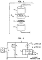
- FIG. 1 it can been seen that a new cathode configuration has been developed to stabilize the cathode fall and suppress the glow-to-arc transition for a wide range of operating conditions. Accordingly, a stable glow discharge can be maintained with the cathode configuration of the present invention for a very wide range of operating pressures (up to atmospheric pressures) and in a wide range of electric field strengths.
- the cathode of the present invention comprises a metal cathode 20 (aluminum, stainless steel, etc.), covered with a perforated dielectric 30 positioned to face an upper electrode 40 .
- the perforated dielectric 30 may be retained on the cathode 20 by a collar 35 that fits over cathode 20 and has an aperture 36 therethrough, or may be formed as part of a cap or cover for the cathode 20 , or may be positioned thereon and held in place thereon in any other manner known in the art.
- the perforated dielectric can be formed of any desired dielectric type substance such as quartz, silicon nitride, silicon carbide, etc., even glass.
- the dielectric is preferably formed of a material that can withstand high temperatures.
- a perforated dielectric comprises a sieve of holes of micron dimensions. The center to center distance of the holes is of the same level of dimension. Hole dimensions are critical for particular applications. In trials discussed hereinafter, a dielectric having 10 ⁇ m (10 micron) holes with a center to center distance between the holes of 12 ⁇ m (12 microns) was used. Hole dimensions can vary from 5 to 200 ⁇ m for the hole diameter and from between 100 ⁇ m to 2 mm for the hole length (thickness of the dielectric).
- the ratio of the hole diameter to the dielectric thickness is an important factor and something that can be controlled depending upon the application. One example of such a ratio could be 10 to 1, the hole diameter being one-tenth of the thickness of the dielectric.
- the perforated dielectric can be made by laser ablation. Blanks for dielectric plates made by Norton International can be used, and function in a desirable matter (a dielectric having a hole diameter of 10 ⁇ m, and a hole length of 0.6 mm). The hole diameter, hole lengths, hole density, and material can be varied to optimize the invention for a particular application. Any silicon carbide wafer can be perforated by laser ablation to form a perforated dielectric for use in connection with the present invention.
- FIG. 2 shows a circuit that has been used to conduct trials of the present invention that will hereinafter be discussed, which can be used with the cathode configuration of the present invention to effect a stable DC glow plasma discharge.
- the present invention allows DC glow discharges, which have a well known instability that limits the operating range, to operate at much higher pressure up to atmospheric pressures. Accordingly, this stabilization allows for applications in many aspects of material processing, pollution remediation, novel lighting devices, and discharge-enhanced combustion.
- the perforated dielectric covering the metal cathode stabilizes the cathode fall region of the DC discharge by breaking the discharge up into a large number of separate micro-channels.
- Each of the holes comprising the perforated dielectric acts as a separate, active current-limiting microchannel. Particle losses due to wall effects and the finite volume of each channel place an upper limit on the electrical conductivity of each channel, and therefore place an upper limit on the current density that it can carry. This prevents the current density from increasing above the threshold for the glow-to-arc transition.
- a dielectric material could be directly deposited in a proper geometry directly onto a cathode by a vapor deposition or other process to apply the dielectric directly to the cathode. In this way, the cathode itself becomes an active current-limiting device.
- a prototype DC glow discharge apparatus was set up using a parallel plate electrode arrangement in an Argon atmosphere of between 1333-13332 Pa (10-100 Torr), to illustrate the present invention
- the phases of the glow-to-arc transition can be readily shown because the transition is sufficiently slow.
- the transition at atmospheric pressures occurs very rapidly and is difficult to observe.
- the present invention is designed to be used at pressures up to atmospheric pressures.
- Current voltage characteristics were recorded for a variety of operating conditions using a standard metal (A1) cathode. The measured curves show the well-known first transition corresponding to the breakdown of gas in the formation of a stable glow discharge, followed by a prominent second transition characteristic of the transition from the glow regime to an arc which creates a filamentary (high current density) channel.
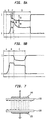
- FIG. 3 a graph of voltage vs. current for applied voltage (VG), glow voltage (Vg) and arc voltage (Vd) is shown for Argon at 5333 Pa ( 40 Torr).
- FIG. 4 shows a graph of voltage vs. current for applied voltage (VG), glow voltage (V g ), and arc voltage (Vd) in Argon at 2666.44 Pa (20 Torr).
- FIGS. 5a and 5b are graphs of the applied voltage and glow-to-arc voltage with and without the perforated dielectric of the present invention. These figures show the stabilization of the glow plasma discharge.
- a first Stage A there is no current.
- the second Stage B voltage is applied, but current stays at zero.
- a third Stage C a glow discharge is achieved.
- the glow quickly goes to arc D, while in FIG. 5b , the perforated dielectric suppresses the glow-to-arc transition and stabilizes the glow discharge such that there is no arc.
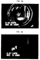
- FIG. 6a is a photograph showing an arc discharge which creates a filamentary (high current density) channel.
- FIG. 6b is a photograph showing a glow discharge characterized by a uniform glow discharge.
- FIG. 7 is a side plan view of an RF discharge embodiment of the present invention wherein the perforated dielectric is positioned over both electrodes.
- electrodes 120 and 140 are both covered by a perforated dielectric 130. Because the current reverses itself in a RF electric field, the dielectric 130 must be positioned over both electrodes 120 and 140 , as both electrodes alternately serve as cathodes. By this configuration, the glow discharge can be sustained under broader operating conditions. Such a configuration results in a frequency independent and size independent device.
- the method and apparatus of the present invention By applying the method and apparatus of the present invention to large volume plasmas at atmospheric pressures, it is possible to increase the energy released during combustion of fuels to levels several times higher than the Heating Value of the fuel. Efforts in this area in the past have failed because the distribution of energy is required over a substantial volume and cannot be concentrated in a small area. Because of the glow-to-arc transition, there has been tendency to produce arcs of a very high energy level with the rest of the volume remaining at a normal combustion level. By suppressing the glow-to-arc transition and stabilizing the plasma glow, the method and apparatus of the present invention overcomes the limitations of the prior attempts and results in an enhancement of the combustion process resulting in much higher energy densities than could be previously achieved.
- Additional applications of the present invention may occur in the field of air pollution remediation where stabilization of the glow-to-arc transition may result in real time destruction of constituents of air emissions from manufacturing operations in remediation of soil and ground water pollution, in large volumes at high pressures.
- the present invention creates large volume plasmas to destroy the polluting vapors at higher efficiencies with reduced cost.
- combustion by-products such as NO x and SO x which have heretofore been destroyed by pulsed corona and barrier discharges.
- the present invention is additionally applicable to the cleaning of lithography sheet surfaces in atmospheric pressures. Additionally, there may be possible utility for large area surface cleaning at atmospheric pressure for curing polymer films. By being able to operate at atmospheric pressure, a great advantage is achieved over the high processing cost required in a vacuum process. Additionally, the present invention can be used for pretreatment of semi-conductors, glasses, and polymers which are to be used for direct metal ion beam processing.
- an atmospheric pressure glow discharge plasma can be used to sterilize biologically contaminated surfaces.
- Current techniques in this area utilize high temperatures, strong chemicals, and/or ultraviolet radiation to sterilize contaminated items.
- problems with these approaches in that the processes are time intensive and potentially hazardous and result in the formation of potentially hazardous by-products. It has been demonstrated that materials exposed to a one-atmosphere pressure glow discharge plasma can be sterilized of biological contaminants in under one minute.
Landscapes
- Engineering & Computer Science (AREA)
- Physics & Mathematics (AREA)
- Plasma & Fusion (AREA)
- Chemical & Material Sciences (AREA)
- Analytical Chemistry (AREA)
- Power Engineering (AREA)
- Spectroscopy & Molecular Physics (AREA)
- Plasma Technology (AREA)
- Investigating, Analyzing Materials By Fluorescence Or Luminescence (AREA)
- Physical Or Chemical Processes And Apparatus (AREA)
- Electron Sources, Ion Sources (AREA)
Applications Claiming Priority (3)
| Application Number | Priority Date | Filing Date | Title |
|---|---|---|---|
| US820013 | 1997-03-18 | ||
| US08/820,013 US5872426A (en) | 1997-03-18 | 1997-03-18 | Glow plasma discharge device having electrode covered with perforated dielectric |
| PCT/US1998/005174 WO1998042002A1 (en) | 1997-03-18 | 1998-03-17 | Glow plasma discharge device |
Publications (3)
| Publication Number | Publication Date |
|---|---|
| EP1012863A1 EP1012863A1 (en) | 2000-06-28 |
| EP1012863A4 EP1012863A4 (en) | 2000-11-15 |
| EP1012863B1 true EP1012863B1 (en) | 2002-12-04 |
Family
ID=25229669
Family Applications (1)
| Application Number | Title | Priority Date | Filing Date |
|---|---|---|---|
| EP98910447A Expired - Lifetime EP1012863B1 (en) | 1997-03-18 | 1998-03-17 | Glow plasma discharge device |
Country Status (9)
| Country | Link |
|---|---|
| US (2) | US5872426A (enExample) |
| EP (1) | EP1012863B1 (enExample) |
| JP (1) | JP2001527689A (enExample) |
| KR (1) | KR20000076338A (enExample) |
| AT (1) | ATE229227T1 (enExample) |
| AU (1) | AU720025B2 (enExample) |
| CA (1) | CA2284242C (enExample) |
| DE (1) | DE69809943T2 (enExample) |
| WO (1) | WO1998042002A1 (enExample) |
Families Citing this family (75)
| Publication number | Priority date | Publication date | Assignee | Title |
|---|---|---|---|---|
| US6198762B1 (en) * | 1996-09-26 | 2001-03-06 | Yuri Krasnov | Supersonic and subsonic laser with RF discharge excitation |
| US6636545B2 (en) | 1996-09-26 | 2003-10-21 | Alexander V. Krasnov | Supersonic and subsonic laser with radio frequency excitation |
| US6879103B1 (en) * | 1997-03-18 | 2005-04-12 | The Trustees Of The Stevens Institute Of Technology | Glow plasma discharge device |
| US6147452A (en) * | 1997-03-18 | 2000-11-14 | The Trustees Of The Stevens Institute Of Technology | AC glow plasma discharge device having an electrode covered with apertured dielectric |
| US6900592B2 (en) * | 1997-03-18 | 2005-05-31 | The Trustees Of The Stevens Institute Of Technology | Method and apparatus for stabilizing of the glow plasma discharges |
| US6461870B2 (en) * | 1998-05-06 | 2002-10-08 | Isotechnika Inc. | 13C glucose breath test for the diagnosis of diabetic indications and monitoring glycemic control |
| US6309610B1 (en) * | 1998-05-27 | 2001-10-30 | Science Applications International Corporation | Non-thermal plasma apparatus utilizing dielectrically-coated electrodes for treating effluent gas |
| US6255777B1 (en) | 1998-07-01 | 2001-07-03 | Plasmion Corporation | Capillary electrode discharge plasma display panel device and method of fabricating the same |
| CN1327486A (zh) * | 1998-12-01 | 2001-12-19 | Sk株式会社 | 薄膜成形设备 |
| US6455014B1 (en) * | 1999-05-14 | 2002-09-24 | Mesosystems Technology, Inc. | Decontamination of fluids or objects contaminated with chemical or biological agents using a distributed plasma reactor |
| US6433480B1 (en) * | 1999-05-28 | 2002-08-13 | Old Dominion University | Direct current high-pressure glow discharges |
| US20020092616A1 (en) * | 1999-06-23 | 2002-07-18 | Seong I. Kim | Apparatus for plasma treatment using capillary electrode discharge plasma shower |
| US7192553B2 (en) * | 1999-12-15 | 2007-03-20 | Plasmasol Corporation | In situ sterilization and decontamination system using a non-thermal plasma discharge |
| US7094322B1 (en) | 1999-12-15 | 2006-08-22 | Plasmasol Corporation Wall Township | Use of self-sustained atmospheric pressure plasma for the scattering and absorption of electromagnetic radiation |
| US6955794B2 (en) * | 1999-12-15 | 2005-10-18 | Plasmasol Corporation | Slot discharge non-thermal plasma apparatus and process for promoting chemical reaction |
| KR20030031879A (ko) | 1999-12-15 | 2003-04-23 | 스티븐스 인스티튜트 오프 테크놀로지 | 구획된 전극 모세관 방전, 비열 플라스마 장치 및화학반응 촉진 방법 |
| US6923890B2 (en) | 1999-12-15 | 2005-08-02 | Plasmasol Corporation | Chemical processing using non-thermal discharge plasma |
| US7029636B2 (en) * | 1999-12-15 | 2006-04-18 | Plasmasol Corporation | Electrode discharge, non-thermal plasma device (reactor) for the pre-treatment of combustion air |
| US6724608B2 (en) * | 2000-01-14 | 2004-04-20 | Paul Hensley | Method for plasma charging a probe |
| KR20000024528A (ko) * | 2000-02-18 | 2000-05-06 | 강정구 | Rf를 이용한 대기압 상온 플라즈마 토치 |
| KR100367132B1 (ko) * | 2000-04-27 | 2003-01-09 | 준 최 | 무전극 방전 장치 |
| US6548957B1 (en) * | 2000-05-15 | 2003-04-15 | Plasmion Displays Llc | Plasma display panel device having reduced turn-on voltage and increased UV-emission and method of manufacturing the same |
| AU2001296568A1 (en) * | 2000-10-04 | 2002-04-15 | Plasmion Displays, Llc | Method of fabricating plasma display panel using laser process |
| US6432280B1 (en) * | 2000-10-23 | 2002-08-13 | Pioneer Industrial Technologies, Inc. | Pollution control device |
| KR100430345B1 (ko) * | 2000-11-28 | 2004-05-04 | (주)에스이 플라즈마 | 대기압에서 저온 플라즈마를 발생시키는 장치 |
| KR100464902B1 (ko) * | 2001-02-12 | 2005-01-05 | (주)에스이 플라즈마 | 대기압에서 저온 플라즈마를 발생시키는 장치 |
| DE10108717C1 (de) * | 2001-02-23 | 2002-07-11 | Bosch Gmbh Robert | Vorrichtung und Verfahren zur Entladung von dielektrischen Oberflächen |
| US20020122896A1 (en) * | 2001-03-02 | 2002-09-05 | Skion Corporation | Capillary discharge plasma apparatus and method for surface treatment using the same |
| US20020139659A1 (en) * | 2001-04-03 | 2002-10-03 | Skion Corporation | Method and apparatus for sterilization of fluids using a continuous capillary discharge atmospheric pressure plasma shower |
| US20020148816A1 (en) * | 2001-04-17 | 2002-10-17 | Jung Chang Bo | Method and apparatus for fabricating printed circuit board using atmospheric pressure capillary discharge plasma shower |
| US20020187066A1 (en) * | 2001-06-07 | 2002-12-12 | Skion Corporation | Apparatus and method using capillary discharge plasma shower for sterilizing and disinfecting articles |
| CA2452939A1 (en) * | 2001-07-02 | 2003-01-16 | Seth Tropper | A novel electrode for use with atmospheric pressure plasma emitter apparatus and method for using the same |
| US20030015505A1 (en) * | 2001-07-19 | 2003-01-23 | Skion Corporation | Apparatus and method for sterilization of articles using capillary discharge atmospheric plasma |
| US20030104141A1 (en) * | 2001-08-27 | 2003-06-05 | Amato-Wierda Carmela C. | Dielectric barrier discharge process for depositing silicon nitride film on substrates |
| EP1451850A2 (en) * | 2001-11-02 | 2004-09-01 | Plasmasol Corporation | Non-thermal plasma slit discharge apparatus |
| US20040050684A1 (en) * | 2001-11-02 | 2004-03-18 | Plasmasol Corporation | System and method for injection of an organic based reagent into weakly ionized gas to generate chemically active species |
| US6821379B2 (en) * | 2001-12-21 | 2004-11-23 | The Procter & Gamble Company | Portable apparatus and method for treating a workpiece |
| US6841201B2 (en) * | 2001-12-21 | 2005-01-11 | The Procter & Gamble Company | Apparatus and method for treating a workpiece using plasma generated from microwave radiation |
| DE10203543B4 (de) * | 2002-01-29 | 2008-04-30 | Je Plasmaconsult Gmbh | Vorrichtung zur Erzeugung eines APG-Plasmas |
| US6919551B2 (en) * | 2002-08-29 | 2005-07-19 | Micron Technology Inc. | Differential column readout scheme for CMOS APS pixels |
| KR100530765B1 (ko) * | 2002-10-04 | 2005-11-23 | 이규왕 | 나노 다공성 유전체를 이용한 플라즈마 발생장치 |
| US20040073221A1 (en) * | 2002-10-11 | 2004-04-15 | Spineco, Inc., A Corporation Of Ohio | Electro-stimulation and medical delivery device |
| US7615070B2 (en) * | 2002-10-11 | 2009-11-10 | Spineco, Inc. | Electro-stimulation and medical delivery device |
| RU2237391C1 (ru) * | 2003-03-17 | 2004-09-27 | Камский государственный политехнический институт | Способ получения тлеющего разряда между жидким электролитным катодом и твердотельным анодом и устройство для его осуществления |
| US8211374B2 (en) | 2003-07-18 | 2012-07-03 | David Richard Hallam | Air cleaning device |
| ATE362648T1 (de) * | 2003-08-14 | 2007-06-15 | Fuji Film Mfg Europ B V | Anordnung, verfahren und elektrode zur erzeugung eines plasmas |
| US8070785B2 (en) | 2003-09-16 | 2011-12-06 | Spineco, Inc. | Bone anchor prosthesis and system |
| WO2005070017A2 (en) * | 2004-01-22 | 2005-08-04 | Plasmasol Corporation | Capillary-in-ring electrode gas discharge generator for producing a weakly ionized gas and method for using the same |
| EP1715898A4 (en) * | 2004-01-22 | 2007-05-30 | Plasmasol Corp | MODULAR STERILIZATION SYSTEM |
| WO2005074333A1 (en) * | 2004-01-30 | 2005-08-11 | Changjo Engineering Co., Ltd. | Apparatus of generating glow plasma on a wide surface under atmospheric pressure |
| RU2258329C1 (ru) * | 2004-05-06 | 2005-08-10 | Камский государственный политехнический институт | Электродный узел |
| US8502108B2 (en) * | 2004-05-28 | 2013-08-06 | Old Dominion University Research Foundation | Method and device for creating a micro plasma jet |
| US8471171B2 (en) * | 2004-05-28 | 2013-06-25 | Robert O. Price | Cold air atmospheric pressure micro plasma jet application method and device |
| US7572998B2 (en) * | 2004-05-28 | 2009-08-11 | Mohamed Abdel-Aleam H | Method and device for creating a micro plasma jet |
| CA2580101A1 (en) * | 2004-09-14 | 2006-03-23 | Spineco, Inc. | Implant device |
| DE102004045804B4 (de) * | 2004-09-22 | 2006-07-27 | Roche Diagnostics Gmbh | Handgerät zum Entnehmen von Blut oder anderen Körperflüssigkeiten |
| US20070048176A1 (en) * | 2005-08-31 | 2007-03-01 | Plasmasol Corporation | Sterilizing and recharging apparatus for batteries, battery packs and battery powered devices |
| US20070104610A1 (en) * | 2005-11-01 | 2007-05-10 | Houston Edward J | Plasma sterilization system having improved plasma generator |
| US9681529B1 (en) * | 2006-01-06 | 2017-06-13 | The United States Of America As Represented By The Secretary Of The Air Force | Microwave adapting plasma torch module |
| WO2009002294A1 (en) * | 2007-06-22 | 2008-12-31 | Carrier Corporation | A method and system for using an ozone generating device for air purification |
| CN101778804A (zh) * | 2007-06-22 | 2010-07-14 | 开利公司 | 使用臭氧与吸附剂和/或颗粒过滤器净化流体 |
| RU2390108C2 (ru) * | 2007-12-03 | 2010-05-20 | Государственное образовательное учреждение высшего профессионального образования "Камская государственная инженерно-экономическая академия" | Способ зажигания тлеющего разряда между жидким электролитом и твердотельным электродом |
| RU2340978C1 (ru) * | 2007-12-06 | 2008-12-10 | Государственное образовательное учреждение высшего профессионального образования "Камская государственная инженерно-экономическая академия" | Электродный узел |
| WO2009133193A1 (en) * | 2008-05-02 | 2009-11-05 | Oerlikon Trading Ag, Truebbach | Plasma treatment apparatus and method for plasma-assisted treatment of substrates |
| US20090297409A1 (en) * | 2008-05-30 | 2009-12-03 | Buchanan Walter R | Discharge plasma reactor |
| US9120073B2 (en) * | 2009-06-05 | 2015-09-01 | Eon Labs, Llc | Distributed dielectric barrier discharge reactor |
| EP3356026B1 (en) | 2015-10-01 | 2022-11-09 | Milton Roy, LLC | Plasma reactor for liquid and gas |
| US12296313B2 (en) | 2015-10-01 | 2025-05-13 | Milton Roy, Llc | System and method for formulating medical treatment effluents |
| US11452982B2 (en) | 2015-10-01 | 2022-09-27 | Milton Roy, Llc | Reactor for liquid and gas and method of use |
| US10882021B2 (en) | 2015-10-01 | 2021-01-05 | Ion Inject Technology Llc | Plasma reactor for liquid and gas and method of use |
| US10187968B2 (en) | 2015-10-08 | 2019-01-22 | Ion Inject Technology Llc | Quasi-resonant plasma voltage generator |
| US10046300B2 (en) | 2015-12-09 | 2018-08-14 | Ion Inject Technology Llc | Membrane plasma reactor |
| US11095088B1 (en) | 2018-02-21 | 2021-08-17 | Zoyka Llc | Multi-pass coaxial molecular gas laser |
| CN112087857A (zh) * | 2019-06-12 | 2020-12-15 | 中国石油化工股份有限公司 | 电晕放电等离子体发生装置 |
| CN114205983B (zh) * | 2021-11-09 | 2024-05-14 | 中国人民解放军军事科学院国防工程研究院工程防护研究所 | 一种诊断等离子体电子密度的测量系统和方法 |
Family Cites Families (12)
| Publication number | Priority date | Publication date | Assignee | Title |
|---|---|---|---|---|
| US3821588A (en) * | 1973-03-08 | 1974-06-28 | Burroughs Corp | Display panel having flat side edges to permit butting together plural panels |
| US3914642A (en) * | 1973-05-17 | 1975-10-21 | Northern Electric Co | Electrical luminescent display devices |
| GB1544172A (en) * | 1976-03-03 | 1979-04-11 | Int Plasma Corp | Gas plasma reactor and process |
| US4698551A (en) * | 1986-03-20 | 1987-10-06 | Laser Corporation Of America | Discharge electrode for a gas discharge device |
| JPH02101740A (ja) * | 1988-10-11 | 1990-04-13 | Anelva Corp | プラズマエッチング装置 |
| IT1246682B (it) * | 1991-03-04 | 1994-11-24 | Proel Tecnologie Spa | Dispositivo a catodo cavo non riscaldato per la generazione dinamica di plasma |
| US5248371A (en) * | 1992-08-13 | 1993-09-28 | General Signal Corporation | Hollow-anode glow discharge apparatus |
| DE4315075A1 (de) * | 1993-02-17 | 1994-11-10 | Fraunhofer Ges Forschung | Anordnung zur Plasmaerzeugung |
| US5387842A (en) * | 1993-05-28 | 1995-02-07 | The University Of Tennessee Research Corp. | Steady-state, glow discharge plasma |
| US5414324A (en) * | 1993-05-28 | 1995-05-09 | The University Of Tennessee Research Corporation | One atmosphere, uniform glow discharge plasma |
| CA2163967C (en) * | 1993-05-28 | 2008-11-04 | John Reece Roth | Method and apparatus for glow discharge plasma treatment of polymer materials at atmospheric pressure |
| JPH08250488A (ja) * | 1995-01-13 | 1996-09-27 | Seiko Epson Corp | プラズマ処理装置及びその方法 |
-
1997
- 1997-03-18 US US08/820,013 patent/US5872426A/en not_active Expired - Lifetime
-
1998
- 1998-03-17 DE DE69809943T patent/DE69809943T2/de not_active Expired - Fee Related
- 1998-03-17 JP JP54070498A patent/JP2001527689A/ja not_active Ceased
- 1998-03-17 AU AU64688/98A patent/AU720025B2/en not_active Ceased
- 1998-03-17 WO PCT/US1998/005174 patent/WO1998042002A1/en not_active Ceased
- 1998-03-17 AT AT98910447T patent/ATE229227T1/de not_active IP Right Cessation
- 1998-03-17 KR KR1019997008439A patent/KR20000076338A/ko not_active Abandoned
- 1998-03-17 CA CA002284242A patent/CA2284242C/en not_active Expired - Fee Related
- 1998-03-17 EP EP98910447A patent/EP1012863B1/en not_active Expired - Lifetime
-
1999
- 1999-02-12 US US09/249,405 patent/US6005349A/en not_active Expired - Lifetime
Also Published As
| Publication number | Publication date |
|---|---|
| CA2284242A1 (en) | 1998-09-24 |
| EP1012863A1 (en) | 2000-06-28 |
| JP2001527689A (ja) | 2001-12-25 |
| CA2284242C (en) | 2006-12-12 |
| DE69809943D1 (de) | 2003-01-16 |
| AU720025B2 (en) | 2000-05-18 |
| AU6468898A (en) | 1998-10-12 |
| DE69809943T2 (de) | 2003-07-17 |
| US6005349A (en) | 1999-12-21 |
| KR20000076338A (ko) | 2000-12-26 |
| EP1012863A4 (en) | 2000-11-15 |
| HK1029222A1 (en) | 2001-03-23 |
| WO1998042002A1 (en) | 1998-09-24 |
| US5872426A (en) | 1999-02-16 |
| ATE229227T1 (de) | 2002-12-15 |
Similar Documents
| Publication | Publication Date | Title |
|---|---|---|
| EP1012863B1 (en) | Glow plasma discharge device | |
| US6147452A (en) | AC glow plasma discharge device having an electrode covered with apertured dielectric | |
| WO1998042002A9 (en) | Glow plasma discharge device | |
| US6900592B2 (en) | Method and apparatus for stabilizing of the glow plasma discharges | |
| US6433480B1 (en) | Direct current high-pressure glow discharges | |
| US6444945B1 (en) | Bipolar plasma source, plasma sheet source, and effusion cell utilizing a bipolar plasma source | |
| Baránková et al. | Fused hollow cathode cold atmospheric plasma | |
| Gavrilov et al. | High-current pulse sources of broad beams of gas and metal ions for surface treatment | |
| US6879103B1 (en) | Glow plasma discharge device | |
| Bárdoš et al. | Radio frequency hollow cathode source for large area cold atmospheric plasma applications | |
| Pessoa et al. | Hollow cathode discharges: low and high-pressure operation | |
| HK1029222B (en) | Glow plasma discharge device | |
| RU2026414C1 (ru) | Способ обработки изделий | |
| EP1176857A1 (en) | DC plasma generator for generation of a non-local, non-equilibrium plasma at high pressure | |
| KR100469552B1 (ko) | 플라즈마 표면 처리 장치 및 방법 | |
| Baránková et al. | Atmospheric pressure plasma sources and processing | |
| Guo et al. | Characteristics of large-area cold atmospheric discharges from radio-frequency microdischarge arrays | |
| Jiang et al. | Study on a novel high-pressure micro-discharge configuration for micro-laser | |
| Chao et al. | Study on a novel high-pressure micro-discharge configuration for micro-laser |
Legal Events
| Date | Code | Title | Description |
|---|---|---|---|
| PUAI | Public reference made under article 153(3) epc to a published international application that has entered the european phase |
Free format text: ORIGINAL CODE: 0009012 |
|
| 17P | Request for examination filed |
Effective date: 19990923 |
|
| AK | Designated contracting states |
Kind code of ref document: A1 Designated state(s): AT BE CH DE DK ES FI FR GB GR IE IT LI LU MC NL PT SE |
|
| A4 | Supplementary search report drawn up and despatched |
Effective date: 20001002 |
|
| AK | Designated contracting states |
Kind code of ref document: A4 Designated state(s): AT BE CH DE DK ES FI FR GB GR IE IT LI LU MC NL PT SE |
|
| RIC1 | Information provided on ipc code assigned before grant |
Free format text: 7H 01J 17/49 A, 7H 01J 37/32 B |
|
| 17Q | First examination report despatched |
Effective date: 20010920 |
|
| GRAG | Despatch of communication of intention to grant |
Free format text: ORIGINAL CODE: EPIDOS AGRA |
|
| GRAG | Despatch of communication of intention to grant |
Free format text: ORIGINAL CODE: EPIDOS AGRA |
|
| GRAG | Despatch of communication of intention to grant |
Free format text: ORIGINAL CODE: EPIDOS AGRA |
|
| GRAH | Despatch of communication of intention to grant a patent |
Free format text: ORIGINAL CODE: EPIDOS IGRA |
|
| GRAH | Despatch of communication of intention to grant a patent |
Free format text: ORIGINAL CODE: EPIDOS IGRA |
|
| GRAA | (expected) grant |
Free format text: ORIGINAL CODE: 0009210 |
|
| AK | Designated contracting states |
Kind code of ref document: B1 Designated state(s): AT BE CH DE DK ES FI FR GB GR IE IT LI LU MC NL PT SE |
|
| PG25 | Lapsed in a contracting state [announced via postgrant information from national office to epo] |
Ref country code: NL Free format text: LAPSE BECAUSE OF FAILURE TO SUBMIT A TRANSLATION OF THE DESCRIPTION OR TO PAY THE FEE WITHIN THE PRESCRIBED TIME-LIMIT Effective date: 20021204 Ref country code: LI Free format text: LAPSE BECAUSE OF FAILURE TO SUBMIT A TRANSLATION OF THE DESCRIPTION OR TO PAY THE FEE WITHIN THE PRESCRIBED TIME-LIMIT Effective date: 20021204 Ref country code: GR Free format text: LAPSE BECAUSE OF FAILURE TO SUBMIT A TRANSLATION OF THE DESCRIPTION OR TO PAY THE FEE WITHIN THE PRESCRIBED TIME-LIMIT Effective date: 20021204 Ref country code: FI Free format text: LAPSE BECAUSE OF FAILURE TO SUBMIT A TRANSLATION OF THE DESCRIPTION OR TO PAY THE FEE WITHIN THE PRESCRIBED TIME-LIMIT Effective date: 20021204 Ref country code: CH Free format text: LAPSE BECAUSE OF FAILURE TO SUBMIT A TRANSLATION OF THE DESCRIPTION OR TO PAY THE FEE WITHIN THE PRESCRIBED TIME-LIMIT Effective date: 20021204 Ref country code: BE Free format text: LAPSE BECAUSE OF FAILURE TO SUBMIT A TRANSLATION OF THE DESCRIPTION OR TO PAY THE FEE WITHIN THE PRESCRIBED TIME-LIMIT Effective date: 20021204 Ref country code: AT Free format text: LAPSE BECAUSE OF FAILURE TO SUBMIT A TRANSLATION OF THE DESCRIPTION OR TO PAY THE FEE WITHIN THE PRESCRIBED TIME-LIMIT Effective date: 20021204 |
|
| REF | Corresponds to: |
Ref document number: 229227 Country of ref document: AT Date of ref document: 20021215 Kind code of ref document: T |
|
| REG | Reference to a national code |
Ref country code: GB Ref legal event code: FG4D |
|
| REG | Reference to a national code |
Ref country code: CH Ref legal event code: EP |
|
| REG | Reference to a national code |
Ref country code: IE Ref legal event code: FG4D |
|
| REF | Corresponds to: |
Ref document number: 69809943 Country of ref document: DE Date of ref document: 20030116 |
|
| PG25 | Lapsed in a contracting state [announced via postgrant information from national office to epo] |
Ref country code: SE Free format text: LAPSE BECAUSE OF FAILURE TO SUBMIT A TRANSLATION OF THE DESCRIPTION OR TO PAY THE FEE WITHIN THE PRESCRIBED TIME-LIMIT Effective date: 20030304 Ref country code: DK Free format text: LAPSE BECAUSE OF FAILURE TO SUBMIT A TRANSLATION OF THE DESCRIPTION OR TO PAY THE FEE WITHIN THE PRESCRIBED TIME-LIMIT Effective date: 20030304 |
|
| PG25 | Lapsed in a contracting state [announced via postgrant information from national office to epo] |
Ref country code: PT Free format text: LAPSE BECAUSE OF FAILURE TO SUBMIT A TRANSLATION OF THE DESCRIPTION OR TO PAY THE FEE WITHIN THE PRESCRIBED TIME-LIMIT Effective date: 20030305 |
|
| PG25 | Lapsed in a contracting state [announced via postgrant information from national office to epo] |
Ref country code: LU Free format text: LAPSE BECAUSE OF NON-PAYMENT OF DUE FEES Effective date: 20030317 |
|
| PG25 | Lapsed in a contracting state [announced via postgrant information from national office to epo] |
Ref country code: MC Free format text: LAPSE BECAUSE OF NON-PAYMENT OF DUE FEES Effective date: 20030331 |
|
| NLV1 | Nl: lapsed or annulled due to failure to fulfill the requirements of art. 29p and 29m of the patents act | ||
| ET | Fr: translation filed | ||
| REG | Reference to a national code |
Ref country code: CH Ref legal event code: PL |
|
| PG25 | Lapsed in a contracting state [announced via postgrant information from national office to epo] |
Ref country code: ES Free format text: LAPSE BECAUSE OF FAILURE TO SUBMIT A TRANSLATION OF THE DESCRIPTION OR TO PAY THE FEE WITHIN THE PRESCRIBED TIME-LIMIT Effective date: 20030627 |
|
| PLBE | No opposition filed within time limit |
Free format text: ORIGINAL CODE: 0009261 |
|
| STAA | Information on the status of an ep patent application or granted ep patent |
Free format text: STATUS: NO OPPOSITION FILED WITHIN TIME LIMIT |
|
| 26N | No opposition filed |
Effective date: 20030905 |
|
| PGFP | Annual fee paid to national office [announced via postgrant information from national office to epo] |
Ref country code: IE Payment date: 20060313 Year of fee payment: 9 |
|
| PGFP | Annual fee paid to national office [announced via postgrant information from national office to epo] |
Ref country code: IT Payment date: 20060331 Year of fee payment: 9 |
|
| PGFP | Annual fee paid to national office [announced via postgrant information from national office to epo] |
Ref country code: GB Payment date: 20070327 Year of fee payment: 10 |
|
| PGFP | Annual fee paid to national office [announced via postgrant information from national office to epo] |
Ref country code: DE Payment date: 20070430 Year of fee payment: 10 |
|
| REG | Reference to a national code |
Ref country code: IE Ref legal event code: MM4A |
|
| PG25 | Lapsed in a contracting state [announced via postgrant information from national office to epo] |
Ref country code: IE Free format text: LAPSE BECAUSE OF NON-PAYMENT OF DUE FEES Effective date: 20070319 |
|
| PGFP | Annual fee paid to national office [announced via postgrant information from national office to epo] |
Ref country code: FR Payment date: 20070319 Year of fee payment: 10 |
|
| GBPC | Gb: european patent ceased through non-payment of renewal fee |
Effective date: 20080317 |
|
| REG | Reference to a national code |
Ref country code: FR Ref legal event code: ST Effective date: 20081125 |
|
| PG25 | Lapsed in a contracting state [announced via postgrant information from national office to epo] |
Ref country code: DE Free format text: LAPSE BECAUSE OF NON-PAYMENT OF DUE FEES Effective date: 20081001 |
|
| PG25 | Lapsed in a contracting state [announced via postgrant information from national office to epo] |
Ref country code: FR Free format text: LAPSE BECAUSE OF NON-PAYMENT OF DUE FEES Effective date: 20080331 |
|
| PG25 | Lapsed in a contracting state [announced via postgrant information from national office to epo] |
Ref country code: GB Free format text: LAPSE BECAUSE OF NON-PAYMENT OF DUE FEES Effective date: 20080317 |
|
| PG25 | Lapsed in a contracting state [announced via postgrant information from national office to epo] |
Ref country code: IT Free format text: LAPSE BECAUSE OF NON-PAYMENT OF DUE FEES Effective date: 20070317 |