EP1011971B1 - Disque a mandrins pour dispositif extremement rapide servant a decorer des reservoirs metalliques - Google Patents
Disque a mandrins pour dispositif extremement rapide servant a decorer des reservoirs metalliques Download PDFInfo
- Publication number
- EP1011971B1 EP1011971B1 EP98923891A EP98923891A EP1011971B1 EP 1011971 B1 EP1011971 B1 EP 1011971B1 EP 98923891 A EP98923891 A EP 98923891A EP 98923891 A EP98923891 A EP 98923891A EP 1011971 B1 EP1011971 B1 EP 1011971B1
- Authority
- EP
- European Patent Office
- Prior art keywords
- carrier
- spindle
- subassemblies
- bushings
- decorating
- Prior art date
- Legal status (The legal status is an assumption and is not a legal conclusion. Google has not performed a legal analysis and makes no representation as to the accuracy of the status listed.)
- Expired - Lifetime
Links
Images


Classifications
-
- B—PERFORMING OPERATIONS; TRANSPORTING
- B41—PRINTING; LINING MACHINES; TYPEWRITERS; STAMPS
- B41F—PRINTING MACHINES OR PRESSES
- B41F17/00—Printing apparatus or machines of special types or for particular purposes, not otherwise provided for
- B41F17/08—Printing apparatus or machines of special types or for particular purposes, not otherwise provided for for printing on filamentary or elongated articles, or on articles with cylindrical surfaces
- B41F17/14—Printing apparatus or machines of special types or for particular purposes, not otherwise provided for for printing on filamentary or elongated articles, or on articles with cylindrical surfaces on articles of finite length
- B41F17/20—Printing apparatus or machines of special types or for particular purposes, not otherwise provided for for printing on filamentary or elongated articles, or on articles with cylindrical surfaces on articles of finite length on articles of uniform cross-section, e.g. pencils, rulers, resistors
- B41F17/22—Printing apparatus or machines of special types or for particular purposes, not otherwise provided for for printing on filamentary or elongated articles, or on articles with cylindrical surfaces on articles of finite length on articles of uniform cross-section, e.g. pencils, rulers, resistors by rolling contact
Definitions
- This invention relates generally to apparatus for applying decorations to cylindrical containers and in particular relates to a spindle carrier disc for a continuous motion high speed apparatus of that type.
- U.S. Patent No. 3,766,851 discloses relatively high speed apparatus for applying decorations to the exterior of cylindrical containers while they are mounted on mandrels or spindles which are disposed along the periphery of a large continuously rotating disc-like carrier. Decorations are applied to the containers by having same engage a rotating blanket of a decorator that is adjacent the periphery of the carrier. During engagement between the containers and the decorating blanket, the containers track the blanket surface through the region where the containers and blanket surface are engaged. To accomplish this tracking, for each angular position of the container measured about the axis of the spindle disc as a center, a device controlled by a closed loop or box cam maintains the container in a precise radial position relative to the axis of the spindle disc.
- This type of decorating equipment includes some relatively heavy elements that move at high speed. Because there must be precise coordination between the various elements, inertia forces, lubrication and operating power are significant engineering design considerations, as are equipment downtime, maintenance costs and setup procedures.
- each of the mandrels or spindles is part of an individual spindle assembly that includes an L-shaped base which must be relatively rigid in order to properly position the cantilevered spindle while decorations are being applied to the container carried thereby.
- the instant invention substantially reduces the weight of the spindle assembly base without sacrificing rigidity.
- the large chamber for the large lubrication pool required in many prior art spindle discs, has been eliminated. Instead, a plurality of relatively small interconnected lubrication chambers are provided. This serves to strengthen the spindle disc. That is, in the prior art so much material was removed to form the large lubrication chamber that disc strength had to be restored by providing a relatively heavy, large thick steel cover for the chamber.
- the multiple relatively small lubrication chambers of the instant invention are interconnected by an annular slot of small cross-section. Such slot is formed without substantially reducing the strength of the spindle disc so that a lightweight aluminum cover is satisfactory for closing the connecting slot and small lubrication chambers.
- the primary object of the instant invention is to provide an improved high speed continuous motion cylindrical container decorator having substantially reduced maintenance and power requirements.
- Another object is to provide a decorator of this type wherein substantial weight reductions have been achieved for the disc-like carrier and reciprocating spindle subassemblies carried thereby.
- Still another object is to provide a construction for this type of decorator to simplify setup procedures and reduce the likelihood that there will be lubrication points that have not been treated properly or have been overlooked completely.
- a further object is to eliminate telescoping shaft and bushing connections in the air/vacuum lines.
- a still further object is to provide a spindle disc construction wherein a hose having a single complete loop therein is used to connect a radially reciprocating spindle assembly to a radially fixed point on the spindle disc.
- Yet another object is to provide a spindle disc construction in which hose connections are made by fittings that do not have moving parts.
- Fig. 1 illustrates continuous motion cylindrical container decorating apparatus of the general type described in the aforesaid U.S. Patent No. 3,766,851 and U.S. Patent No. 5,111,742 .
- the apparatus of Fig. 1 includes infeed conveyor chute 15 which receives undecorated containers in the for of cans 16, each open at one end thereof, from a supply (not shown) and places cans 16 in arcuate cradles or pockets 17 formed by aligned depressions in the outer edges of spaced rings 31, 32 ( Fig. 2 ). The latter are fixedly secured to disc-like spindle carrier 18 which is keyed to horizontal drive shaft 19.
- a fixture comprising concentric rings 45 and 64 spaced by angled standoffs 48 is interposed between pocket rings 31, 32 and carrier 18.
- Bolts 46 secure ring 45 against front surface 65 of carrier 18 and bolts 47 mount pocket rings 31, 32 on ring 64.
- the latter is of larger diameter than ring 45 and is positioned forward thereof.
- FIG. 2 Horizontally extending spindles or mandrels 20 ( Fig. 2 ) are also mounted to carrier 18, with each mandrel 20 being in spaced horizontal alignment with an individual pocket 17 while passing through a short region extending downstream from infeed conveyor 15. In this short region, undecorated cans 16 are moved horizontally rearward by a deflector (not shown), being transferred from each cradle 17 to an individual mandrel 20. Suction applied through an axial passage extending to the outboard or front end 20a of mandrel or spindle 20 draws container 16 rearward (to the left with respect to Fig. 2 ) to final seating position on spindle 20.
- cans 16 While mounted on mandrels 20, cans 16 are decorated by being brought into engagement with continuously rotating image transfer mat or blanket 21 of the multicolored printing press decorating section indicated generally by reference numeral 22. Thereafter, and while mounted to mandrels 20, each decorated can 16 is coated with a protective film of varnish applied thereto by engagement with the periphery of applicator roll 23 in the overvarnish unit indicated generally by numeral 24. Cans 16 with decorations and protective coatings thereon are then transferred from spindles 20 to suction cups (not shown) mounted near the periphery of transfer wheel 27 while the latter rotates about shaft 28 as a center. Cans 16 carried by transfer wheel 27 are deposited on generally horizontal pins 29 which project from chain type output conveyor 30 that carries cans 16 through a curing oven (not shown).
- each spindle 20 should be properly loaded with a can 16. If sensor 33 detects that a spindle 20 is unloaded or is not properly loaded, then before this particular spindle 20 enters the decorating zone wherein printing blanket 21 normally engages can 16 on mandrel 20, this unloaded or misloaded spindle 20 is moved to a tripped or "no-print" position. As a tripped mandrel 20 moves through the decorating zone it will be spaced from the periphery of blanket 21. This no-print position is achieved by controlling double acting cylinder 34 to trip subframe 35 having spindle carrier shaft 19 mounted thereon, by moving subframe 35 to the left with respect to Fig.
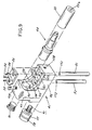
- Spindle 20 is part of spindle subassembly 40 ( Fig. 9 ) that also includes L-shaped base 41, stub shaft 44, two guide rods 51, 52 and two cam follower rollers 57, 58.
- base 41 includes horizontal main section 42 and arm 43 that projects radially outward from main section 42, being at the rear thereof and perpendicular thereto ( Fig. 3 ).
- Guide rods 51, 52 extend radially inward from main section 42 being secured by respective bolts 54, 55 that extend through apertures in plate 53 and are received by threaded apertures 151, 152 at the radially outward ends of respective rods 51, 52.
- Figs. 5 and 6 illustrate naked spindle disc 18 that is provided with central aperture 66 which receives drive shaft 19. Key 67 ( Fig. 2 ) is received by slot 68 ( Fig. 5 ) in the wall defining aperture 66 to provide alignment, and the ringfeeder 144 provides a driving connection and adjustment of runout between carrier shaft 19 and spindle disc 18.
- the latter mounts twenty-four spindle subassemblies 40 as shown partially in Fig. 4 , there being equal angular spacings between the subassemblies 40. Such spacings are established by a pair of radial holes 73, 74 that extend inward from disc periphery 81 and house respective cylindrical bushings 71, 72 ( Fig. 2 ).
- Reciprocating guide rods 51, 52 extend through bearing passages that are provided by the respective bushings 71, 72.
- each axial bore 76 intersects with four radial holes 73, 73, 74, 74 at the radially inward ends of the latter.
- Small cross-section circular slot 77 milled in rear surface 75 interconnects all twelve bores 76.
- Each bushing 71, 72 is retained in a respective radial hole 73, 74 by an individual ring-like cap or holder 80 ( Fig. 3 ).
- Holders 80 are at the radially outer ends of bushings 71, 72, and the radially inner ends of bushings 71, 72 rest upon interior ledges of holes 73, 74.
- Each holder 80 contains two ring seals 82, 82 that surround each guide rod 51, 52.
- Three bolts 83 that are received by apertures 84 ( Fig. 8 ) in carrier periphery 81 secure each holder 80 to carrier 18.
- each bushing 71, 72 in annular undercut 99 at the radially inner surface of holder 80 accurately positions seals 82, 82 from beneath holder 80 relative to the bearing passages provided by bushings 71, 72 to obtain improved operation of guide rods 51, 52 as they reciprocate in the bearing passages of bushings 71, 72.
- each of the twenty-four apertures 86 ( Fig. 5 ) in the front surface of carrier 18 receives an individual fitting 85 ( Fig. 2 ).
- grease injected at fitting 85 travels a circuitous path to relief fitting 87 at aperture 88 ( Fig. 8 ) at carrier periphery 81.
- this circuitous path from fitting 85 to fitting 87 includes axial portion 91, annular cutout 92 inside of bushing 71, axial portion 93, cutout 94 inside of bushing 72, axial portion 95 and radial portion 96.
- vacuum and pressure are supplied to forward end 20a of mandrel 20 through an individual flexible hose 101 having opposite ends clamped to fittings 102, 103 that are connected, respectively, to carrier 18 and spindle assembly 40. That is, straight fitting 102 is screwed into an aperture of movable valve element 104 that is secured by bolts 107 to the front side of carrier 18, and L-shaped fitting 103 is screwed into aperture 108 of base 41. Aperture 108 is at the front end of main section 42 (see Figs. 9-14 ). Wear plate 106 secured to the front of movable valve member 104, is in sliding engagement with stationary valve member 105 at interface 109.
- fittings 102, 103 do not have parts that are free to swivel or otherwise move relative to each other once fitting 103 is secured to mandrel subassembly 40 and fitting 102 is secured to movable valve member 104. Further, hose 101 contains a complete relatively large diameter loop, and fittings 102, 103 are angularly offset so that hose 101 will not rub against itself as fitting 103 reciprocates radially. In addition, hose 101 is positioned so that it will not rub against other elements.
- Main section 42 of base 41 is provided with axial passage 110 that extends rearward from aperture 108 to the radially inner end of passage 111 in arm 43.
- Passage 112 extends to the radially outward edge of arm 43 where the radially outward end 109 of passage 111 is plugged.
- Elongated opening 112 at a midpoint of passage 111 connects with arm aperture 113 which houses the rear end of mandrel shaft 44.
- Passages (not shown) extend from aperture 113 to connect with front end 20a of mandrel 20.
- Arm 43 is also provided with diagonal passage 114 that extends to recess 116 wherein one end of stub shaft 61 ( Fig. 2 ) is positioned.
- Base 41 weighs considerably less than prior art base 119 shown by the phantom outline in Figs. 13 and 14 , and other mandrel support bases that can be replaced by base 41. That is, base 41 does not include the sections between the solid line and phantom outline in Figs. 13 and 14 , whereas prior art base 119 includes those sections plus substantially the entire base 41. It is noted that for base 41, resistance to bending between arm 43 and main section 42 is maintained at a satisfactory level by thin triangular gussets 126 ( Fig. 9 ) which provide reinforcement at each side of arm 43 where it joins main section 42.
- main section 42 is relatively thin so that the rotational axis of mandrel 20, located at center A ( Fig. 2 ) of cantilevered shaft 44 can be relatively close to the radially outward ends of bushings 71, 72. This serves to reduce the bending moments that act upon guide shafts 51, 52 and translate into bending forces that cause rapid wear of bushings 71, 72 in prior art constructions.
Landscapes
- Specific Conveyance Elements (AREA)
- Blow-Moulding Or Thermoforming Of Plastics Or The Like (AREA)
- Toys (AREA)
- Adornments (AREA)
- Details Of Rigid Or Semi-Rigid Containers (AREA)
- Making Paper Articles (AREA)
- Manufacturing Of Magnetic Record Carriers (AREA)
- Feeding And Guiding Record Carriers (AREA)
- Sliding-Contact Bearings (AREA)
- Finish Polishing, Edge Sharpening, And Grinding By Specific Grinding Devices (AREA)
- Moulds For Moulding Plastics Or The Like (AREA)
- Infusion, Injection, And Reservoir Apparatuses (AREA)
Claims (13)
- Appareil à mouvement continu pour décorer des contenants cylindriques, ledit appareil comprenant une section de décoration (22) et une section de transport qui porte les contenants à travers une zone de décoration dans laquelle des décorations sont appliquées aux contenants, ladite section de transport comprenant:un porteur (18) tournant continuellement sur un axe de porteur, une pluralité de sous-ensembles de broches (40) montés sur ledit porteur le long de sa périphérie avec des espacements angulaires égaux entre des sous-ensembles précités adjacents, lesdits sous-ensembles étant installés pour exécuter un mouvement alternatif radialement relativement audit axe de porteur comme centre;chacun desdits sous-ensembles incluant une base en forme de L (41), une broche (20) montée sur ladite base pour la rotation autour d'un axe de broche qui est parallèle audit axe de porteur, ladite base incluant une section principale (42) parallèle audit axe de broche et un bras (43) s'étendant radialement vers l'extérieur depuis ladite section principale à son extrémité arrière, ladite broche (20) se trouvant sur un support en porte-à-faux (44) qui fait saillie vers l'avant depuis ledit bras (43) et repose sur ladite section principale (42), au moins des première et deuxième tiges de guidage (51, 52) s'étendant radialement vers l'intérieur depuis ladite section principale (42) et étant reçues dans des premier et deuxième passages de palier respectifs s'étendant radialement (73, 74) de première et deuxième douilles respectives (71, 72) qui sont montées fixement sur ledit porteur (18), les passages de palier précités (73, 74) étant ouverts à ladite périphérie dudit porteur;lesdites première et deuxième douilles (71, 72) étant disposées dans des passages radiaux individuels (73, 74) s'étendant radialement vers l'intérieur depuis ladite périphérie dudit porteur (18), ladite première tige étant en amont de ladite deuxième tige, caractérisé en ce que:une pluralité de réservoirs de graisse (92, 94) dont chacun est formé par un passage transversal s'étendant vers l'avant depuis une surface arrière dudit porteur (18) et se croisant radialement avec les extrémités internes de premier, deuxième, troisième et quatrième desdits passages radiaux (72, 74) qui reçoivent lesdites première et deuxième tiges de guidage (51, 52) d'un premier desdits ensembles ainsi que lesdites première et deuxième tiges de guidage (51, 52) d'un deuxième desdits ensembles, lesdits premier et deuxième sous-ensembles étant adjacents l'un à l'autre.
- Appareil pour décorer des contenants cylindriques tel que défini par la revendication 1, dans lequel lesdits passages transversaux sont reliés par une fente annulaire dans ladite surface arrière, ladite fente ayant une zone relativement petite en section transversale en comparaison avec une zone en section transversale de chacun desdits passages transversaux.
- Appareil pour décorer des contenants cylindriques tel que défini par la revendication 1, dans lequel le porteur possède une surface avant opposée à ladite surface arrière; une entrée de graisse individuelle (85) associée à chacun desdits sous-ensembles et une sortie de décharge de graisse individuelle (87) associée à chacun desdits sous-ensembles; lesdites entrée (85) et sortie (87) étant sur ledit porteur (18); pour chacun desdits sous-ensembles, son entrée (85) et sortie (87) associées précitées étant reliées par un passage de graisse (92, 94) qui comprend des interfaces entre lesdites tiges de guidage (51, 52) dudit ensemble et desdites douilles (71, 72) associés dans lesquels lesdites tiges de guidage (51, 52) s'étendent, ladite entrée (85) étant devant ladite première tige, et ladite sortie (87) étant derrière ladite deuxième tige.
- Appareil pour décorer des contenants cylindriques tel que défini par la revendication 2, dans lequel lesdites entrées (85) sont accessibles à ladite surface avant dudit porteur (18), et lesdites sorties (87) se situent à ladite périphérie dudit porteur (18).
- Appareil pour décorer des contenants cylindriques tel que défini par la revendication 1, dans lequel il y a des goussets minces (126) aux côtés opposés de ladite section principale (42) à ladite extrémité arrière et s'étendant entre ladite section principale (42) et ledit bras (43) pour renforcer ladite base, moyennant quoi ladite base résiste efficacement à une flexion lorsqu'une force radialement vers l'intérieur est appliquée à ladite broche (20) durant la décoration d'un contenant porté par ladite broche (20).
- Appareil pour décorer des contenants cylindriques tel que défini par la revendication 5, dans lequel ladite broche (20) ayant un diamètre d'approximativement 2,6 pouces (6,60 cm), et pendant que des décorations sont appliquées à un contenant qui est monté sur ladite broche (20), l'espacement entre ledit axe de broche et lesdites douilles (71, 72) est aussi petit qu'approximativement 5,2 pouces (13,21 cm).
- Appareil pour décorer des contenants cylindriques tel que défini par la revendication 1, dans lequel pour chacun desdits sous-ensembles, il y a un tuyau flexible (101) ayant une première extrémité reliée à ladite section principale à son extrémtié avant pour fournir un vide et de l'air comprimé sélectivement à ladite broche (20), ledit tuyau ayant une seconde extrémité reliée à une section de vanne mobile (104) montée sur ledit porteur (18) et en prise fonctionnelle avec une section de vanne (105) relativement stationnaire à laquelle le vide et de l'air comprimé sont fournis;
ledit tuyau (101) définissant au moins une boucle complète qui s'expanse lorsque ledit axe de broche se déplace vers ledit axe de porteur. - Appareil pour décorer des contenants cylindriques tel que défini par la revendication 7, dans lequel ladite première extrémité dudit tuyau (101) est décalée angulairement de ladite seconde extrémité dudit tuyau.
- Appareil pour décorer des contenants cylindriques tel que défini par la revendication 8, dans lequel il y a un premier raccord d'air (103) reliant ledit tuyau (101) à ladite section principale de ladite base et un deuxième raccord d'air (102) reliant ledit tuyau (101) à ladite section de vanne mobile (104);
lesdits premier et deuxième raccords d'air étant construits de façon que, pendant que ledit porteur tourne, tous les éléments dudit premier raccord d'air (103) soient fixés les uns par rapport aux autres et par rapport à ladite base, et tous les éléments dudit deuxième raccord d'air (102) sont fixés les uns par rapport aux autres et par rapport audit porteur. - Appareil pour décorer des contenants cylindriques tel que défini par la revendication 4, dans lequel le support (18) possède une surface avant opposée à ladite surface arrière;
une entrée de graisse individuelle (85) associée à chacun desdits sous-ensembles et une sortie de décharge de graisse individuelle (87) associée à chacun desdits sous-ensembles; lesdites entrées (85) et lesdites sorties (87) se trouvant sur ledit porteur (18);
pour chacun desdits sous-ensembles, ses entrée (85) et sortie (87) associées étant reliées par un passage de graisse (92, 94) qui inclut des interfaces entre lesdites tiges (51, 52) dudit ensemble associé et desdites douilles (71, 72) dans lesquelles lesdites tiges (51, 52) s'étendent, ladite entrée étant devant ladite première tige, et ladite sortie étant derrière ladite deuxième tige. - Appareil pour décorer des contenants cylindriques tel que défini par la revendication 7, dans lequel ledit mandrin (20) ayant un diamètre d'approximativement 2,6 pouces (6,60 cm), et pendant que des décorations sont appliquées à un contenant qui est monté sur ledit mandrin (20), l'espacement entre ledit axe de mandrin et lesdites douilles (71, 72) est aussi faible qu'approximativement 5,2 pouces (13,21 cm).
- Appareil pour décorer des contenants cylindriques tel que défini par la revendication 2, dans lequel le porteur possède une surface avant opposée à ladite surface arrière; une entrée de graisse individuelle (85) associée à chacun desdits sous-ensembles et une sortie de décharge de graisse individuelle (87) associée à chacun desdits sous-ensembles;
lesdites entrées (85) et lesdites sorties (87) se trouvant sur ledit porteur (18);
pour chacun desdits sous-ensembles, son entrée (85) et sortie (87) associées précitées étant reliées par un passage de graisse (92, 94) qui comprend des interfaces entre lesdites tiges (51, 52) dudit ensemble associé et desdites douilles (71, 72) dans lesquelles lesdites tiges (51, 52) s'étendent, ladite entrée étant devant ladite première tige et ladite sortie étant derrière ladite deuxième tige. - Appareil pour décorer des contenants cylindriques tel que défini par la revendication 1, dans lequel il y a un capuchon de retenue associé (80) semblable à une rondelle pour chacune desdites douilles (71, 72), chacun desdits capuchons de retenue (80) contenant une bague de scellement de graisse (82) et étant fixée audit porteur à ladite périphérie dans une position fonctionnelle pour bloquer un mouvement radialement vers l'extérieur de ladite douille associée (71, 72);
chacune desdites douilles (71, 72) ayant une extrémité radialement vers l'extérieur qui s'étend dans une portion contre-dépouillée (99) dans ledit capuchon (80) moyennant quoi ledit capuchon (80) est piloté sur ladite douille (71, 72) qui est associée audit capuchon (80).
Applications Claiming Priority (3)
| Application Number | Priority Date | Filing Date | Title |
|---|---|---|---|
| US08/876,409 US5799574A (en) | 1997-06-16 | 1997-06-16 | Spindle disc for high speed can decorators |
| US876409 | 1997-06-16 | ||
| PCT/US1998/011190 WO1998057808A1 (fr) | 1997-06-16 | 1998-06-02 | Disque a mandrins pour dispositif extremement rapide servant a decorer des reservoirs metalliques |
Publications (3)
| Publication Number | Publication Date |
|---|---|
| EP1011971A1 EP1011971A1 (fr) | 2000-06-28 |
| EP1011971A4 EP1011971A4 (fr) | 2001-01-17 |
| EP1011971B1 true EP1011971B1 (fr) | 2009-07-29 |
Family
ID=25367648
Family Applications (1)
| Application Number | Title | Priority Date | Filing Date |
|---|---|---|---|
| EP98923891A Expired - Lifetime EP1011971B1 (fr) | 1997-06-16 | 1998-06-02 | Disque a mandrins pour dispositif extremement rapide servant a decorer des reservoirs metalliques |
Country Status (16)
| Country | Link |
|---|---|
| US (1) | US5799574A (fr) |
| EP (1) | EP1011971B1 (fr) |
| JP (1) | JP4482620B2 (fr) |
| KR (1) | KR20010013885A (fr) |
| CN (1) | CN1087689C (fr) |
| AT (1) | ATE437754T1 (fr) |
| AU (1) | AU727160B2 (fr) |
| BR (1) | BR9810141A (fr) |
| CA (1) | CA2294371C (fr) |
| DE (1) | DE69841018D1 (fr) |
| HK (1) | HK1029774A1 (fr) |
| IL (1) | IL133530A (fr) |
| PL (1) | PL193234B1 (fr) |
| RU (1) | RU2191699C2 (fr) |
| TR (1) | TR199903111T2 (fr) |
| WO (1) | WO1998057808A1 (fr) |
Cited By (1)
| Publication number | Priority date | Publication date | Assignee | Title |
|---|---|---|---|---|
| US11279146B2 (en) | 2017-09-19 | 2022-03-22 | Ball Corporation | Container decoration apparatus and method |
Families Citing this family (20)
| Publication number | Priority date | Publication date | Assignee | Title |
|---|---|---|---|---|
| US6167805B1 (en) * | 1999-02-10 | 2001-01-02 | Sequa Corporation | Mandrel carrier for high speed can decorators |
| US7011728B2 (en) * | 2001-07-19 | 2006-03-14 | Berry Plastics Corporation | Container-labeling and-printing synchronization apparatus and process |
| US20070129151A1 (en) * | 2001-08-20 | 2007-06-07 | Crowder Robert W Jr | Game Conversion Method |
| US6840166B2 (en) * | 2002-06-12 | 2005-01-11 | Machine Engineering, Inc. | Mandrel trip apparatus |
| US6769357B1 (en) | 2003-06-05 | 2004-08-03 | Sequa Can Machinery, Inc. | Digital can decorating apparatus |
| US6920822B2 (en) * | 2003-09-03 | 2005-07-26 | Stolle Machinery Company, Llc | Digital can decorating apparatus |
| EP1782951B8 (fr) * | 2005-11-03 | 2008-05-28 | Ball Packaging Europe Holding GmbH & Co. KG | Mandrin pour l'impression digitale |
| US8726964B2 (en) * | 2006-05-10 | 2014-05-20 | Decoral System Usa Corp. | Apparatuses and methods for decorating objects |
| US8931864B2 (en) * | 2009-05-21 | 2015-01-13 | Inx International Ink Company | Apparatuses for printing on generally cylindrical objects and related methods |
| US9475276B2 (en) | 2011-04-27 | 2016-10-25 | Stolle Machinery Company, Llc | Can decorator machine, ink station assembly therefor, and can decorating method employing same |
| US8707866B2 (en) | 2012-03-21 | 2014-04-29 | James M. Jeter | Rail guide mounting assembly for mandrel trip apparatus |
| US20130247784A1 (en) * | 2012-03-26 | 2013-09-26 | James M. Jeter | Can decorator assembly with dual cam mandrel guidance |
| WO2014158145A1 (fr) * | 2013-03-26 | 2014-10-02 | Jeter James M | Ensemble machine de décoration de boîte à guidage de mandrin à double came |
| NL1040447C2 (nl) * | 2013-10-15 | 2015-04-16 | Upg Engineering | Mandrel wiel voor continuous motion druk-of lakmachine. |
| US10739705B2 (en) | 2016-08-10 | 2020-08-11 | Ball Corporation | Method and apparatus of decorating a metallic container by digital printing to a transfer blanket |
| EP3496952B1 (fr) | 2016-08-10 | 2024-05-29 | Ball Corporation | Procédé et appareil de décoration d'un récipient métallique par impression numérique sur un blanchet de transfert |
| US10780714B2 (en) | 2016-12-16 | 2020-09-22 | Stolle Machinery Company, Llc | Mandrel for printing necked cans |
| US10155375B2 (en) * | 2016-12-16 | 2018-12-18 | Stolle Machinery Company, Llc | Mandrel for printing necked cans |
| BR112020018499A2 (pt) * | 2018-03-14 | 2020-12-29 | Stolle Machinery Company, Llc | Conjunto de decorador |
| MX2021005328A (es) | 2018-11-09 | 2022-10-10 | Ball Corp | Un rodillo medidor para un ensamble de estación de tinta de un decorador y un método para decorar un contenedor con la decoración. |
Family Cites Families (15)
| Publication number | Priority date | Publication date | Assignee | Title |
|---|---|---|---|---|
| US3227070A (en) * | 1964-09-04 | 1966-01-04 | Ward E Brigham | High speed can printing press |
| US3567043A (en) * | 1968-08-05 | 1971-03-02 | Sun Chemical Corp | Transfer assembly for use with container printing machines |
| US3586175A (en) * | 1968-11-15 | 1971-06-22 | Sun Chemical Corp | Transfer assembly for use with container printing machines |
| US3766851A (en) * | 1971-11-15 | 1973-10-23 | Sun Chemical Corp | Continuous can printer and handling apparatus |
| US3996851A (en) * | 1975-07-17 | 1976-12-14 | Crown Cork & Seal Company, Inc. | Container printing apparatus |
| US4048917A (en) * | 1975-09-26 | 1977-09-20 | Sun Chemical Corporation | Continuous motion printing apparatus |
| US4140053A (en) * | 1977-06-16 | 1979-02-20 | Sun Chemical Corporation | Mandrel mounting and trip mechanism for continuous motion decorator |
| US4337719A (en) * | 1981-04-16 | 1982-07-06 | Van Dam Machine Corporation Of America | Mandrel support means for container decorating apparatus |
| US4498387A (en) * | 1983-10-21 | 1985-02-12 | Adolph Coors Company | Cam assembly for skip-print mandrel wheel assembly |
| US4771879A (en) * | 1987-07-01 | 1988-09-20 | Adolph Coors Company | Container transfer system |
| US4921093A (en) * | 1988-05-09 | 1990-05-01 | Sequa Corporation | Infeed means for high speed continuous motion can decorator |
| US5111742A (en) * | 1990-08-13 | 1992-05-12 | Sequa Corporation | Mandrel trip subassembly for continuous motion can decorators |
| US5186100A (en) * | 1992-01-16 | 1993-02-16 | Sequa Corporation | Interchangeable inker having enclosed transmission |
| US5609100A (en) * | 1995-06-07 | 1997-03-11 | Sequa Corporation | Face valve apparatus for continuous motion can decorator |
| US5572927A (en) * | 1995-08-31 | 1996-11-12 | Sequa Corporation | Vertical track for mandrel assembly of continuous motion can decorators |
-
1997
- 1997-06-16 US US08/876,409 patent/US5799574A/en not_active Expired - Lifetime
-
1998
- 1998-06-02 EP EP98923891A patent/EP1011971B1/fr not_active Expired - Lifetime
- 1998-06-02 RU RU2000100917/12A patent/RU2191699C2/ru active
- 1998-06-02 PL PL337437A patent/PL193234B1/pl not_active IP Right Cessation
- 1998-06-02 CA CA002294371A patent/CA2294371C/fr not_active Expired - Lifetime
- 1998-06-02 CN CN98807415A patent/CN1087689C/zh not_active Expired - Fee Related
- 1998-06-02 KR KR1019997011907A patent/KR20010013885A/ko not_active Application Discontinuation
- 1998-06-02 JP JP50445799A patent/JP4482620B2/ja not_active Expired - Lifetime
- 1998-06-02 DE DE69841018T patent/DE69841018D1/de not_active Expired - Lifetime
- 1998-06-02 TR TR1999/03111T patent/TR199903111T2/xx unknown
- 1998-06-02 WO PCT/US1998/011190 patent/WO1998057808A1/fr not_active Application Discontinuation
- 1998-06-02 AT AT98923891T patent/ATE437754T1/de not_active IP Right Cessation
- 1998-06-02 BR BR9810141-2A patent/BR9810141A/pt not_active IP Right Cessation
- 1998-06-02 IL IL13353098A patent/IL133530A/en not_active IP Right Cessation
- 1998-06-02 AU AU76075/98A patent/AU727160B2/en not_active Expired
-
2000
- 2000-12-04 HK HK00107752A patent/HK1029774A1/xx not_active IP Right Cessation
Cited By (2)
| Publication number | Priority date | Publication date | Assignee | Title |
|---|---|---|---|---|
| US11279146B2 (en) | 2017-09-19 | 2022-03-22 | Ball Corporation | Container decoration apparatus and method |
| US11745517B2 (en) | 2017-09-19 | 2023-09-05 | Ball Coporation | Container decoration apparatus and method |
Also Published As
| Publication number | Publication date |
|---|---|
| PL337437A1 (en) | 2000-08-14 |
| CN1087689C (zh) | 2002-07-17 |
| WO1998057808A1 (fr) | 1998-12-23 |
| CN1264337A (zh) | 2000-08-23 |
| IL133530A0 (en) | 2001-04-30 |
| EP1011971A1 (fr) | 2000-06-28 |
| EP1011971A4 (fr) | 2001-01-17 |
| TR199903111T2 (xx) | 2000-10-23 |
| CA2294371A1 (fr) | 1998-12-23 |
| DE69841018D1 (de) | 2009-09-10 |
| IL133530A (en) | 2004-08-31 |
| AU727160B2 (en) | 2000-12-07 |
| PL193234B1 (pl) | 2007-01-31 |
| AU7607598A (en) | 1999-01-04 |
| KR20010013885A (ko) | 2001-02-26 |
| US5799574A (en) | 1998-09-01 |
| CA2294371C (fr) | 2008-11-18 |
| RU2191699C2 (ru) | 2002-10-27 |
| ATE437754T1 (de) | 2009-08-15 |
| JP4482620B2 (ja) | 2010-06-16 |
| JP2002504056A (ja) | 2002-02-05 |
| HK1029774A1 (en) | 2001-04-12 |
| BR9810141A (pt) | 2000-08-08 |
Similar Documents
| Publication | Publication Date | Title |
|---|---|---|
| EP1011971B1 (fr) | Disque a mandrins pour dispositif extremement rapide servant a decorer des reservoirs metalliques | |
| EP1165318B1 (fr) | Support de mandrin pour appareils de decoration de boites metalliques fonctionnant a grande vitesse | |
| US5282375A (en) | Spin flow necking apparatus and method of handling cans therein | |
| US5233922A (en) | Ink fountain for a can coater | |
| US4771879A (en) | Container transfer system | |
| US3124065A (en) | Method and machine for printing plastic bottles | |
| EP0494659A2 (fr) | Appareil de revêtement de boîtes avec un déactivateur répondant à l'absence de pièces | |
| US5111742A (en) | Mandrel trip subassembly for continuous motion can decorators | |
| EP0847332B1 (fr) | Rail vertical pour ensemble mandrin d'appareils de decoration de boites en mouvement continu | |
| US4942955A (en) | Container transfer system | |
| MXPA99011829A (en) | Spindle disc for high speed can decorators | |
| CA2096303A1 (fr) | Appareil a retreinte et methode de manipulation des contenants metalliques | |
| MXPA98001618A (en) | Vertical track for mandrel unit of container movement cans |
Legal Events
| Date | Code | Title | Description |
|---|---|---|---|
| PUAI | Public reference made under article 153(3) epc to a published international application that has entered the european phase |
Free format text: ORIGINAL CODE: 0009012 |
|
| 17P | Request for examination filed |
Effective date: 20000117 |
|
| AK | Designated contracting states |
Kind code of ref document: A1 Designated state(s): AT BE DE ES FR GB GR IT NL SE |
|
| A4 | Supplementary search report drawn up and despatched |
Effective date: 20001205 |
|
| AK | Designated contracting states |
Kind code of ref document: A4 Designated state(s): AT BE DE ES FR GB GR IT NL SE |
|
| RIC1 | Information provided on ipc code assigned before grant |
Free format text: 7B 41F 17/08 A, 7B 41F 17/22 B |
|
| GRAP | Despatch of communication of intention to grant a patent |
Free format text: ORIGINAL CODE: EPIDOSNIGR1 |
|
| RAP1 | Party data changed (applicant data changed or rights of an application transferred) |
Owner name: STOLLE MACHINERY COMPANY, LLC |
|
| GRAS | Grant fee paid |
Free format text: ORIGINAL CODE: EPIDOSNIGR3 |
|
| GRAA | (expected) grant |
Free format text: ORIGINAL CODE: 0009210 |
|
| AK | Designated contracting states |
Kind code of ref document: B1 Designated state(s): AT BE DE ES FR GB GR IT NL SE |
|
| REG | Reference to a national code |
Ref country code: GB Ref legal event code: FG4D |
|
| REF | Corresponds to: |
Ref document number: 69841018 Country of ref document: DE Date of ref document: 20090910 Kind code of ref document: P |
|
| PG25 | Lapsed in a contracting state [announced via postgrant information from national office to epo] |
Ref country code: SE Free format text: LAPSE BECAUSE OF FAILURE TO SUBMIT A TRANSLATION OF THE DESCRIPTION OR TO PAY THE FEE WITHIN THE PRESCRIBED TIME-LIMIT Effective date: 20090729 Ref country code: ES Free format text: LAPSE BECAUSE OF FAILURE TO SUBMIT A TRANSLATION OF THE DESCRIPTION OR TO PAY THE FEE WITHIN THE PRESCRIBED TIME-LIMIT Effective date: 20091109 Ref country code: AT Free format text: LAPSE BECAUSE OF FAILURE TO SUBMIT A TRANSLATION OF THE DESCRIPTION OR TO PAY THE FEE WITHIN THE PRESCRIBED TIME-LIMIT Effective date: 20090729 |
|
| PG25 | Lapsed in a contracting state [announced via postgrant information from national office to epo] |
Ref country code: BE Free format text: LAPSE BECAUSE OF FAILURE TO SUBMIT A TRANSLATION OF THE DESCRIPTION OR TO PAY THE FEE WITHIN THE PRESCRIBED TIME-LIMIT Effective date: 20090729 |
|
| PLBE | No opposition filed within time limit |
Free format text: ORIGINAL CODE: 0009261 |
|
| STAA | Information on the status of an ep patent application or granted ep patent |
Free format text: STATUS: NO OPPOSITION FILED WITHIN TIME LIMIT |
|
| 26N | No opposition filed |
Effective date: 20100503 |
|
| PG25 | Lapsed in a contracting state [announced via postgrant information from national office to epo] |
Ref country code: GR Free format text: LAPSE BECAUSE OF FAILURE TO SUBMIT A TRANSLATION OF THE DESCRIPTION OR TO PAY THE FEE WITHIN THE PRESCRIBED TIME-LIMIT Effective date: 20091030 |
|
| REG | Reference to a national code |
Ref country code: FR Ref legal event code: ST Effective date: 20110228 |
|
| PG25 | Lapsed in a contracting state [announced via postgrant information from national office to epo] |
Ref country code: IT Free format text: LAPSE BECAUSE OF FAILURE TO SUBMIT A TRANSLATION OF THE DESCRIPTION OR TO PAY THE FEE WITHIN THE PRESCRIBED TIME-LIMIT Effective date: 20090729 |
|
| PG25 | Lapsed in a contracting state [announced via postgrant information from national office to epo] |
Ref country code: FR Free format text: LAPSE BECAUSE OF NON-PAYMENT OF DUE FEES Effective date: 20100630 |
|
| PGFP | Annual fee paid to national office [announced via postgrant information from national office to epo] |
Ref country code: GB Payment date: 20170531 Year of fee payment: 20 Ref country code: DE Payment date: 20170530 Year of fee payment: 20 |
|
| PGFP | Annual fee paid to national office [announced via postgrant information from national office to epo] |
Ref country code: NL Payment date: 20170614 Year of fee payment: 20 |
|
| REG | Reference to a national code |
Ref country code: DE Ref legal event code: R071 Ref document number: 69841018 Country of ref document: DE |
|
| REG | Reference to a national code |
Ref country code: NL Ref legal event code: MK Effective date: 20180601 |
|
| REG | Reference to a national code |
Ref country code: GB Ref legal event code: PE20 Expiry date: 20180601 |
|
| PG25 | Lapsed in a contracting state [announced via postgrant information from national office to epo] |
Ref country code: GB Free format text: LAPSE BECAUSE OF EXPIRATION OF PROTECTION Effective date: 20180601 |