EP1011406B1 - Adaptateur et distributeur pour rouleaux de produits a ame creuse - Google Patents
Adaptateur et distributeur pour rouleaux de produits a ame creuse Download PDFInfo
- Publication number
- EP1011406B1 EP1011406B1 EP98943534A EP98943534A EP1011406B1 EP 1011406 B1 EP1011406 B1 EP 1011406B1 EP 98943534 A EP98943534 A EP 98943534A EP 98943534 A EP98943534 A EP 98943534A EP 1011406 B1 EP1011406 B1 EP 1011406B1
- Authority
- EP
- European Patent Office
- Prior art keywords
- plunger
- dispenser
- adapter
- coreless roll
- opening
- Prior art date
- Legal status (The legal status is an assumption and is not a legal conclusion. Google has not performed a legal analysis and makes no representation as to the accuracy of the status listed.)
- Expired - Lifetime
Links
Images


Classifications
-
- A—HUMAN NECESSITIES
- A47—FURNITURE; DOMESTIC ARTICLES OR APPLIANCES; COFFEE MILLS; SPICE MILLS; SUCTION CLEANERS IN GENERAL
- A47K—SANITARY EQUIPMENT NOT OTHERWISE PROVIDED FOR; TOILET ACCESSORIES
- A47K10/00—Body-drying implements; Toilet paper; Holders therefor
- A47K10/24—Towel dispensers, e.g. for piled-up or folded textile towels; Toilet-paper dispensers; Dispensers for piled-up or folded textile towels provided or not with devices for taking-up soiled towels as far as not mechanically driven
- A47K10/32—Dispensers for paper towels or toilet-paper
- A47K10/34—Dispensers for paper towels or toilet-paper dispensing from a web, e.g. with mechanical dispensing means
- A47K10/38—Dispensers for paper towels or toilet-paper dispensing from a web, e.g. with mechanical dispensing means the web being rolled up with or without tearing edge
- A47K10/40—Dispensers for paper towels or toilet-paper dispensing from a web, e.g. with mechanical dispensing means the web being rolled up with or without tearing edge with extensible or collapsible roll supports or roll spindles
Definitions
- This invention pertains to the field of commercial and consumer roll form products, absorbent paper products, which includes toilet tissue and paper towels. More specifically, this invention relates to an improved dispenser and method of dispensing a coreless roll of absorbent paper product.
- Product is normally loaded by mounting the roll on a spindle in a manner similar to the ubiquitous bathroom toilet roll dispenser.
- the spindle passes through or otherwise penetrates the inner space of the core.
- Some dispensers include pegs that penetrate the hollow space within the core for only a limited extent, as demonstrated in U.S. Patents 390,084, 2,905,404 and 3,878,998 to Lane, Simmons and Lazzari, respectively
- coreless rolls of products such as, for example, toilet tissue have appeared on the market, primarily in Europe. These coreless rolls are wound throughout the entire diameter of the roll.
- coreless rolls are ecologically superior to cored rolls because they lack the central core made of plastic, cardboard or other material. in addition, more product can be provided in the space that would otherwise have been occupied by the core.
- Cored rolls are more expensive to manufacture than coreless rolls because of the expense of making the cores and joining the cores to the product.
- coreless rolls have the advantage of being less subject to pilferage in commercial locations because of their inherent incompatibility with conventional dispensers.
- coreless roll products have dispensing problems that are difficult to overcome.
- Coreless rolls do not fit into conventional core roll dispensers.
- coreless rolls are less likely to be pilfered because they are incompatible with conventional dispensing systems, the lack of a core and spindle passing through the product that can be locked makes it relatively difficult to keep the coreless format product secure.
- dispensers for coreless rolls typically include an enclosed surface that supports the roll as it turns, and an opening through which the product is passed. While functional, these dispensers have some undesirable characteristics, including an inability to control drag resistance to withdrawal of the product; the fact that the product actually touches the inside of the dispenser, which might be considered unsanitary by some consumers; and an inability to provide 180 degree product access to the consumer.
- Some dispensers for coreless rolls have pressure plates and pins that project into the side of the roll between the layers of product. It can be difficult to center the roll during loading of these dispenser without a centering device and the pressure plate and pins can easily be pried back to release the roll from the dispenser.
- the problems described above are addressed by the present invention which encompasses an adapter for converting a core roll product dispenser into a dispenser for a coreless roll product having a pair of depressions defined in the ends of the coreless roll.
- the adapter includes: (1) a housing defining a central cavity and an opening at an end of the central cavity; (2) a retractable plunger having a distal end, a central shaft, and a base, the retractable plunger being configured so the base and a first portion of the central shaft is retained in the housing and the distal end and a second portion of the central shaft extends through the opening at an end of the central cavity so the plunger is adapted to penetrate a depression defined at an end of a coreless roll product; (3) resilient means in communication with the plunger, the resilient means being configured to apply a force against the plunger so the plunger is adapted to retract into the central cavity when a greater opposing force is applied against its distal end during loading and extend when the greater opposing force is removed; and (4) attachment means for securing the adapter to a core roll product dispenser.
- the distal end of the plunger hereby extends from the opening at the end of the housing for a distance that is greater than the width of the plunger.
- the housing of the adapter may further includes a mounting base so the adapter may be more easily attached to a core roll product dispenser.
- the resilient means in communication with the plunger may be a spring, clip, sponge, elastomeric material or the like which can be compressed, wound or drawn so the plunger may be retracted and which exerts a force while compressed, wound or drawn so the plunger can be extended.
- the base of the plunger may be configured to define an opening to a cavity at the interior of the plunger.
- the resilient means may protrude into the cavity at the interior of the plunger.
- the resilient means is a spring, the spring may protrude into the base of the plunger.
- the opening at the end of the central cavity may be circular.
- the opening may be triangular, square, diamond, semi-circular, "X", “Y” or “T” -shaped or the like.
- the opening at the end of the central cavity will match the cross-section of the plunger.
- the plunger may have cross-section that is circular, triangular, square, diamond, semi-circular, "X", "Y” or “T” -shaped or the like.
- the plunger has a cross-section width of at least 1 centimeter. If the plunger has a circular cross-section, it is desirable that the diameter be at least 1 centimeter.
- the distal end of the plunger may have a radius of curvature and desirably defines a hemisphere. Of course, other geometries are contemplated for the shape of the distal end of the plunger. It is also contemplated that the plunger may have a narrow width or a variable width. example, if the plunger has a cross-section width of about 1 centimeter, it is desirable for the distal end of the plunger to extend more than about 1 centimeter from the opening at the end of the housing.
- the distal end of the plunger may extend for 1.25 centimeters, 1. 5 centimeters, 1.75 centimeters, 2.0 centimeters , or 2.25 centimeters or more.
- a greater extension of the plunger helps provides greater penetration into the depressions defined at the ends of the coreless roll product and helps to prevent pilferage of the coreless roll product from the dispenser.
- a retracting means in communication with the retractable plunger may be used for retracting the plunger against the force applied by the resilient means.
- the retracting means may be a knob, a lever and cam mechanism, a pull or the like.
- a locking means for holding the retractable plunger in an extended position may be included in the adapter.
- the locking means may be a cam, lever, ratchet, cotter pin or the like.
- the locking means may be activated by a key or pin.
- the retractable plunger may further include a retaining means for preventing the retractable plunger from passing entirely through the opening at an end of the central cavity.
- This retaining means may be, for example, a flange, a lip, a pin, a wedge or similar structure.
- the present invention also encompasses a dispenser for a coreless roll product having a pair of depressions defined in the ends of the coreless roll.
- the dispenser includes: a frame; mounting means for permitting the frame to be mounted to a stationary surface such as a wall; and a coreless roll securing means for securing a coreless roll product for rotation within the frame.
- the coreless roll securing means contains at least one element including: (1) a housing defining a central cavity and an opening at an end of the central cavity; (2) a retractable plunger having a distal end, a central shaft, and a base, the retractable plunger being configured so the base and a first portion of the central shaft is retained in the housing and the distal end and a second portion of the central shaft extends through the opening at an end of the central cavity so the plunger is adapted to penetrate a depression defined at an end of a coreless roll product; (3) resilient means in communication with the plunger, the resilient means being configured to apply a force against the plunger so the plunger is adapted to retract into the central cavity when a greater opposing force is applied against its distal end during loading and extend when the greater opposing force is removed, whereby radial displacement of the coreless roll with respect to the frame is prevented during use and wherein the distal end of the plunger extends from the opening at the end of the housing for a distance that is greater than the width of the plunger
- the mounting means for the dispenser may be, for example, an opening defined in the frame for a securing member such as a bolt.
- Other mounting means such as clips, pins, screws, latches and the like may also be used.
- the coreless roll securing means may further include a pair of opposed arms that are connected to the frame.
- the dispenser may further include biasing means for resiliently biasing at least one of the opposed arms toward the coreless roll.
- the biasing means may be in the form of at least one of the opposed arms being constructed out of a resilient material, so that arm (or arms) is configured so as to be slightly displaced when a coreless roll is secured within the dispenser.
- the coreless roll securing means of the dispenser is composed of at least one of the elements described above. These elements include resilient means in communication with the plunger.
- the resilient means may be a spring, clip, sponge, elastomeric material or the like which can be compressed, wound or drawn so the plunger may be retracted and which exerts a force While compressed, wound or drawn so the plunger can be extended.
- the base of the plunger may be configured to define an opening to a cavity at the interior of the plunger.
- the resilient means may protrude into the cavity at the interior of the plunger.
- the resilient means is a spring, the spring may protrude into the base of the plunger.
- the opening at the end of the central cavity may be circular.
- the opening may be triangular, square, diamond, semi-circular. "X", “Y” or “T” -shaped or the like.
- the opening at the end of the central cavity will match the cross-section of the plunger.
- the plunger may have cross-section that is circular, triangular, square, diamond, semi-circular, "X", "Y” or “T” -shaped or the like.
- the plunger has a cross-section width of at least 1 centimeter. If the plunger has a circular cross-section, it is desirable that the diameter be at least 1 centimeter.
- the distal end of the plunger may have a radius of curvature and desirably defines a hemisphere. Of course, other geometries are contemplated for the shape of the distal end of the plunger. It is also contemplated that the plunger may have a narrow width or a variable width.
- the plunger has a cross-section width of about 1 centimeter, it is desirable for the distal end of the plunger to extend more than about 1 centimeter. from the opening at the end of the housing.
- the distal end of the plunger may extend for 1.25 centimeters, 1. 5 centimeters, 1.75 centimeters, 2.0 centimeters , or 2.25 centimeters or more.
- a greater extension of the plunger helps provides greater penetration into the depressions defined at the ends of the coreless roll product and helps to prevent pilferage of the coreless roll product from the dispenser.
- a retracting means in communication with the retractable plunger may be used for retracting the plunger against the force applied by the resilient means.
- the retracting means may be a knob. a lever and cam mechanism, a pull or the like.
- a locking means for holding the retractable plunger in an extended position may be included in the adapter.
- the locking means may be a cam, lever, ratchet, cotter pin or the like.
- the locking means may be activated by a key or pin.
- the retractable plunger may further include a retaining means for preventing the retractable plunger from passing entirely through the opening at an end of the central cavity.
- This retaining means may be, for example, a flange, a lip, a pin, a wedge or similar structure.
- FIG. 1 there is shown (not necessarily to scale) an illustration of an exemplary adapter 10 for converting a core roll product dispenser into a dispenser for a coreless roll product having a pair of depressions defined in the ends of the coreless roll.
- the adapter includes a housing 12 defining a central cavity 14 and an opening 16 at an end 18 of the central cavity 14.
- the adapter contains a retractable plunger 20 having a distal end 22, a central shaft 24, and a base 26.
- the adapter also includes a resilient means 28 in communication with the plunger 20.
- An attachment means 30 is also included on the adapter for securing the adapter to a core roll product dispenser.
- a backing plate "P" may be attached to the housing 12 to keep the resilient means 28 contained within the adapter 10 and to allow for convenient placement of the plunger 20 into the central cavity 14 of the housing 12.
- the retractable plunger 20 is configured so the base 26 and a first portion 32 of the central shaft 24 is retained in the housing 12 and the distal end 22 and a second portion 34 of the central shaft 24 extends through the opening 16 at an end of the central cavity 14 so the plunger is adapted to penetrate a depression defined at an end of a coreless roll product.
- the plunger may be configured so it essentially fixed or unable to rotate about an axis. In such case, it is desirable that the plunger be constructed of materials providing low levels of friction to allow the coreless roll to rotate freely. Alternatively, the plunger may be configured so it may rotate freely. It is contemplated that the plunger may be configured so it is able to rotate with the coreless roll during dispensing.
- the retractable plunger may further include a retaining means for preventing the retractable plunger from passing entirely through the opening at an end of the central cavity.
- the base 26 of the plunger may serve as the retaining means.
- the width of the base 26 is greater than the width of the opening 16 at the end 18 of the central cavity 14. This difference in physical size prevents the plunger from passing entirely through the opening.
- retaining means may be used. Examples may include, but are not limited to, flanges, lips, pins, collars, rings, wedges, clips, posts, chains, leads, or similar structures or devices.
- the resilient means 28 is configured to provide or apply a force against the plunger 20 so the plunger 20 is adapted to retract into the central cavity 14 when a greater opposing force is applied against its distal end 22 during loading and extend when the greater opposing force is removed.
- the resilient means in communication with the plunger may be a spring, clip, sponge, elastomeric material or the like which can be compressed, wound or drawn so the plunger may be retracted and which exerts a force while compressed, wound or drawn so the plunger can be extended.
- the force provided or applied by the resilient means serves two purposes.
- the resilient means allows the plungers to retract during the loading process.
- the distance between the two adapters is fixed so it is just slightly larger than the width of the roll.
- the plungers must be able to retract in order to load the roll.
- the force provided or applied by the resilient means is used to retain the roll when the diameter of the roll is very small.
- the force must be balanced so it retains a nearly depleted roll but does not apply too much pressure to prevent the roll from rotating on the fixed plunger.
- the base of the plunger 20 may be configured to define an opening 36 to a cavity 38 at the interior of the plunger 20.
- the resilient means 28 may protrude into the cavity 38 at the interior of the plunger.
- the resilient means is a spring, the spring may protrude into the base of the plunger.
- the housing 12 of the adapter 10 may further include a mounting base 40 so the adapter may be more easily attached to a core roll product dispenser.
- the mounting base 40 may be configured to provide a large footprint that provides more stability and/or surface area. A large surface area may be advantageous if adhesives are used (alone or in combination with other attachment means) to join the adapter to a core roll product dispenser.
- FIG. 5 is an illustration of a portion of an arm typically found on conventional core roll format product dispensers.
- the illustration shows a dispensing arm 50 defining an opening 52.
- This opening 52 is normally configured to receive a spindle (not shown) that passes through the center of a core roll product as in a conventional bathroom tissue dispenser. Alternatively and/or additionally, the opening 52 may be adapted to receive a spindle on which the core roll product was wound or otherwise provided with.
- Conventional core roll product dispensers typically have two of these dispensing arms (with openings 52) mounted in a frame. Some conventional dispensers may have sides instead of arms and may have openings configured in the sides. In either case, the arms or sides and corresponding openings are separated by a distance that is slightly greater than the width of the roll of the core roll product to be dispensed.
- FIG. 6 is an illustration of an exemplary adapter mounted on the conventional core roll product dispensing arm 50 shown in FIG. 5.
- the adapter 10 fits into the opening 52 shown in FIG. 5.
- a portion of the adapter housing 12 is shown extending from the arm 50.
- a plunger 20 is shown protruding from an opening 16 at an end the housing 12.
- Mounting adapters 10 on each arm of a conventional core roll product dispenser quickly and easily converts a conventional dispenser to a coreless roll product dispenser.
- Retractable plungers 20 protruding from each arm are adapted to fit into depressions defined at each end of the coreless roll product.
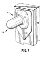
- FIG. 7 is an illustration of another exemplary adapter mounted on the conventional core roll product dispensing arm 50 shown in FIG. 5.
- This adapter is configured with a mounting base 40 attached to the housing 12 generally as shown in FIG. 4.
- the large mounting base 40 stabilizes the adapter 10 when forces are applied during loading and/or dispensing.
- the large mounting base 40 also provides a greater area for adhesive attachment if such attachment means are used.
- the opening 16 at the end 18 of the central cavity 14 may be circular.
- the opening 16 may also be any suitable shape or cross-section.
- the opening 16 may be triangular, square, diamond, semi-circular, "X", “Y” or “T” -shaped or the like.
- the opening at the end of the central cavity will match the cross-section of the plunger.
- the plunger may have a cross-section that is circular, triangular, square, diamond, semi-circular, "X", "Y” or “T” -shaped or the like.
- the plunger it is desirable for the plunger to have a cross-section width that is slightly greater than the width of the depression in the end of the coreless roll product. This configuration helps secure the roll when loaded, prevents overspin of the roll during dispensing, and assists in holding the roll as the roll is depleted. For example, if the depressions defined in both ends of the coreless roll have a diameter of slightly less than 1 centimeter (e.g., -0.9 cm) the plunger desirably will have a diameter or width of about 1 centimeter or slightly greater than 1 centimeter.
- the plunger has a cross-section width of at least 1 centimeter (approximately 1/2 inch). If the plunger has a circular cross-section, it is desirable that the diameter be at least 1 centimeter.
- the distal end of the plunger may have a radius of curvature and desirably defines a hemisphere.
- the rounded tip serves as a centering device for loading the roll and eases loading by providing a leading edge.
- the straight sides of the plunger help keep the roll from wobbling during dispensing, help the roll rotate freely and avoid damage to the roll during dispensing.
- the plunger may have a narrow width or a variable width.
- the distal end of the plunger extends from the opening at the end of the housing for a distance that is greater than the width of the plunger. For example, if the plunger has a cross-section width of about 1 centimeter, it is desirable for the distal end of the plunger to extend more than about 1 centimeter from the opening at the end of the housing. As a further example, the distal end of the plunger may extend for 1.25 centimeters, 1. 5 centimeters, 1.75 centimeters. 2.0 centimeters, or 2.25 centimeters or more. A greater extension of the plunger helps provides greater penetration into the depressions defined at the ends of the coreless roll product.
- a retracting means in communication with the retractable plunger may be used for retracting the plunger against the force applied by the resilient means.
- the retracting means may be a knob, a lever and cam mechanism, a pull or the like. This feature is optional and may be located opposite the plunger (i.e., on the opposite side of the housing as the plunger).
- a locking means for holding the retractable plunger in an extended position may be included in the adapter.
- the locking means may be a cam, lever, ratchet, cotter pin or the like.
- the locking means may be activated by a key or pin.
- Such a locking means would be desirable for adapters used in environments where pilferage of product may be encountered.
- the locking means on the plunger would discourage unloading of the coreless roll by making it even more difficult to push back or retract the plungers out of the depressions defined in the ends of the coreless roll product.
- the present invention also encompasses a dispenser for dispensing a coreless roll product having a pair of depressions defined in the ends of the coreless roll.
- a dispenser for dispensing a coreless roll product having a pair of depressions defined in the ends of the coreless roll.
- Many different types of products may be produced in a coreless roll format.
- commercial and consumer absorbent products such as shop towels, nonwoven fabrics, wipers, bathroom tissue and paper towels are often distributed and dispensed in roll format.
- FIGS. 8-10 there is shown a dispenser 100 for dispensing coreless roll products 200 (shown in broken lines) having a pair of depressions defined in the ends of the coreless roll.
- the dispenser 100 includes a frame 114 that has mounting holes 116 defined therein for permitting the frame to be mounted to a stationary surface, such as a wall.
- the dispenser 100 further includes a coreless roll securing mechanism 118 for securing a coreless roll 200 of product (e.g., bathroom tissue) for rotation within the frame 114.
- the coreless roll securing mechanism 118 includes a first arm 120, a second, central arm 122 and a third arm 124.
- the dispenser 100 depicted in FIG. 8 is designed to accommodate two rolls of coreless roll product (e.g., bathroom tissue), much in the manner of many conventional dispensers that are available for commercial application.
- the outer arms 120, 124 are constructed so they are rigid and will not move.
- the outer arms 120, 124 may be made of a resilient material, such as spring steel, and are configured so they will be slightly displaced when a coreless roll is secured between the central arm 122 and the respective outer arms 120, 124. In this way, the outer arms 120, 124 will bias the respective coreless roll 200 toward the central arm 122.
- the coreless roll securing mechanism 118 is designed to prevent radial displacement of the coreless rolls 200 with respect to the frame 114 of the dispenser 100 during use, so that a coreless roll can be dispensed without fear of radial displacement during use as confidently as a conventional cored roll of absorbent paper product can be.
- each element 128 is configured essentially in accordance with the adapter construction shown in FIG. 1.
- each element may include a housing 12 defining a central cavity 14 and an opening 16 at an end 18 of the central cavity 14.
- the housing may be an integral part of the respective arms 120, 122 , and 124 (shown in FIG. 8) or may be a discrete unit that is attached to each of the arms.
- Each element includes a retractable plunger 20 having a distal end 22, a central shaft 24, and a base 26.
- Each element also includes a resilient means 28 in communication with the plunger 20.
- the elements 128 of the securing mechanism 118 may optionally include an attachment means 30 as shown for the adapter construction of FIG. 1.
- the attachment means may be used if the housing is constructed as a discrete unit and is not integral with the arms of the securing mechanism (i.e., if the housing is not molded, welded, constructed, formed, etc. as part of the arms of the securing mechanism).
- Other features of the elements 128 of the securing mechanism 118 are essentially in accordance with the adapter construction as shown in FIGS. 2-4.
- the elements 128 may be constructed to include a backing plate be attached to the housing to keep the resilient means contained within the element and to allow for convenient placement of the plunger into the central cavity of the housing.
- the retractable plunger is configured so the base and a first portion of the central shaft is retained in the housing and the distal end and a second portion of the central shaft extends through the opening at an end of the central cavity so the plunger is adapted to penetrate a depression defined at an end of a coreless roll product.
- the plunger may be configured so it is essentially fixed or unable to rotate about an axis. In such case, it is desirable that the plunger be constructed of materials providing low levels of friction to allow the coreless roll to rotate freely. Alternatively, the plunger may be configured so it may rotate freely. It is contemplated that the plunger may be configured so it is able to rotate with the coreless roll during dispensing.
- the retractable plunger may further include a retaining means for preventing the retractable plunger from passing entirely through the opening at an end of the central cavity.
- the base of the plunger may serve as the retaining means. This may be accomplished by constructing the plunger so the width of its base is greater than the width of the opening at the end of the central cavity . This difference in physical size prevents the plunger from passing entirely through the opening.
- retaining means may be used. Examples may include, but are not limited to, flanges, lips, pins, collars, rings, wedges, clips, posts, chains, leads, or similar structures or devices.
- the resilient means is configured to provide or apply a force against the plunger so the plunger is adapted to retract into the central cavity when a greater opposing force is applied against its distal end during loading and extend when the greater opposing force is removed.
- the resilient means in communication with the plunger may be a spring, clip, sponge, elastomeric material or the like which can be compressed, wound or drawn so the plunger may be retracted and which exerts a force while compressed, wound or drawn so the plunger can be extended.
- the base of the plunger may be configured to define an opening to a cavity at the interior of the plunger.
- the resilient means may protrude into the cavity at the interior of the plunger.
- the resilient means is a spring, the spring may protrude into the base of the plunger.
- retractable plungers 20 extend inwardly from the respective elements 128 toward where the coreless roll 200 of product will be held during operation. These retractable plungers 20 are specifically designed to penetrate the depressions defined at each end of the coreless roll to secure the coreless roll against pilferage and to prevent radial displacement of the coreless roll during use.
- the arms 120 and 124 are constructed out of resilient material, it will be appreciated that the biasing provided by the resiliency of arms will aid the plungers 20 in penetrating depressions defined at the ends of the coreless roll and enhance the securement of the coreless rolls within the dispenser 100 during use.
- the dispenser 100 includes a cover 130 that is hinged to the frame 114 by hinges 132.
- a sliding window 134 may be provided in the cover 130 to selectively expose the roll 200 of coreless roll product that is being dispensed at a particular point in time, and to deny access to the other roll or vacated mounting location.
- the cover 130, hinges 132. and the sliding window 134 are conventional.
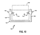
- FIGS. 9 and 10 illustrate an exemplary dispenser 140 for dispensing a coreless roll 200 of product.
- the dispenser 140 includes a frame 142, which is embodied as a relatively simplified shield about the space where the coreless roll 200 will be positioned during use.
- the frame 142 has mounting holes 144 defined in a rear portion thereof for mounting the dispenser 140 to a stationary surface, such as a wall.
- the dispenser 140 further includes a coreless roll. securing mechanism 146 that is embodied as a first arm 148 and a second arm 150.
- both of the elements needs to be configured so that its plunger is retractable to achieve satisfactory operation of the present invention (e.g., to load of the dispenser). Desirably, both or all elements will be configured so the plungers will be retractable.
- a method of instating a coreless roll having a pair of depressions defined at opposite ends of the roll in a dispenser is descrided in the following.
- the method includes the steps of: (a) applying a force to at least one retractable plunger to retract the plunger, (b) orienting a coreless roll with a pair of depressions at opposite ends of the roll so at least one depression is adjacent at least one plunger; (c) securing the coreless roll to the dispenser by penetrating at least one depression in the coreless roll with at least one plunger.
- the method of the present invention encompasses embodiments where step (b) involves orienting the coreless roll so both depressions are adjacent plungers.
- the method of the present invention further encompasses embodiments where step (c) involves penetrating both depressions with plungers.
- the method of the present invention may further involve resiliently biasing the plungers into the coreless roll during operation.
Abstract
Claims (19)
- Adaptateur (10) pour transformer un distributeur de produit en rouleau à noyau en un distributeur (100) pour produit en rouleau sans noyau (200) ayant une paire de dépressions définies dans ses extrémités, l'adaptateur (10) comprenant :un boítier (12) définissant une cavité centrale (14) et une ouverture (16) au niveau d'une extrémité (18) de la cavité centrale (14) ;un piston-plongeur (20) rétractable ayant une extrémité distale (22), un axe central (24) et une base (26), le piston-plongeur (20) rétractable étant configuré de façon que la base (26) et une première portion (32) de l'axe central (24) soient retenues dans le boítier (12) et que l'extrémité distale (22) et une seconde portion (34) de l'axe central (24) sortent au travers de l'ouverture (16) au niveau d'une extrémité (18) de la cavité centrale (14), le piston-plongeur (20) étant ainsi adapté à pénétrer dans une dépression définie au niveau d'une extrémité d'un produit en rouleau sans noyau (200) ;un moyen élastique (28) en communication avec le piston-plongeur (20), le moyen élastique (28) étant configuré pour appliquer une force contre le piston-plongeur (20) de sorte que le piston-plongeur (20) est adapté à se rétracter dans la cavité centrale (14) lorsqu'une force d'opposition supérieure est appliquée contre son extrémité distale (22) au cours du chargement, et à sortir lorsque cesse la force d'opposition supérieure ; etun moyen de fixation (30) pour fixer l'adaptateur (10) à un distributeur de produit en rouleau à noyau ;grâce à quoi l'extrémité distale (22) dudit piston-plongeur (20) sort par l'ouverture (16) au niveau de l'extrémité du boítier (12) sur une distance qui est supérieure à la largeur du piston-plongeur (20).
- Adaptateur (10) selon la revendication 1, dans lequel le boítier (12) comprend en outre une plaque de montage (40).
- Distributeur (100) pour un produit en rouleau sans noyau (200) ayant une paire de dépressions définies dans ses extrémités, le distributeur (100) comprenant :un châssis (114;142) ;des moyens de montage pour permettre au châssis (114;142) d'être monté sur une surface fixe telle qu'un mur ; etun moyen de fixation (118;146) de rouleau sans noyau pour monter un produit en rouleau sans noyau (200) en rotation au sein du châssis (114;142), le moyen de fixation (118;146) de rouleau sans noyau comprenant au moins un élément incluant :un boítier (12) définissant une cavité centrale (14) et une ouverture (16) au niveau d'une extrémité (18) de la cavité centrale (14) ;un piston-plongeur (20) rétractable ayant une extrémité distale (22), un axe central (24) et une base (26), le piston-plongeur (20) rétractable étant configuré de façon que la base (26) et une première portion (32) de l'axe central (24) soient retenues dans le boítier (12) et que l'extrémité distale (22) et une seconde portion (34) de l'axe central (24) sortent au travers de l'ouverture (16) au niveau d'une extrémité (18) de la cavité centrale (14), le piston-plongeur (20) étant ainsi adapté à pénétrer dans une dépression définie au niveau d'une extrémité d'un produit en rouleau sans noyau (200) ; etun moyen élastique (28) en communication avec le piston-plongeur (20), le moyen élastique (28) étant configuré pour appliquer une force contre le piston-plongeur (20) de sorte que le piston-plongeur (20) est adapté à se rétracter dans la cavité centrale (14) lorsqu'une force d'opposition supérieure est appliquée contre son extrémité distale (22) au cours du chargement, et à se projeter lorsque cesse la force d'opposition supérieure ;grâce à quoi, en service, le rouleau sans noyau (200) est empêché d'avoir un déplacement radial par rapport audit châssis (114; 142) ;grâce à quoi l'extrémité distale (22) dudit piston-plongeur (20) sort par l'ouverture (16) au niveau de l'extrémité du boítier (12) sur une distance qui est supérieure à la largeur du piston-plongeur (20).
- Distributeur (100) selon la revendication 3, dans lequel ledit moyen de montage comprend une ouverture (116;144) définie dans ledit châssis (114;142) pour un élément de fixation tel qu'un boulon.
- Distributeur (100) selon la revendication 3 ou 4, dans lequel le moyen de fixation (118;146) de rouleau sans noyau comprend en outre une paire de bras opposés (120,122,124 ; 148,150) qui sont connectés au châssis (114;142) et dans lequel il se trouve, monté sur une face intérieure de chaque bras (120,122,124 ; 148,150), un élément comprenant :un boítier (12) définissant une cavité centrale (14) et une ouverture (16) au niveau d'une extrémité (18) de la cavité centrale (14) ;un piston-plongeur (20) rétractable ayant une extrémité distale (22), un axe central (24) et une base (26), le piston-plongeur (20) rétractable étant configuré de façon que la base (26) et une première portion de l'axe central (24) soient retenues dans le boítier (12) et que l'extrémité distale (22) et une seconde portion de l'axe central (24) sortent au travers de l'ouverture (16) au niveau d'une extrémité (18) de la cavité centrale (14), le piston-plongeur (20) étant ainsi adapté à pénétrer dans une dépression définie au niveau d'une extrémité d'un produit en rouleau sans noyau (200) ; etun moyen élastique (28) en communication avec le piston-plongeur (20), le moyen élastique (28) étant configuré pour appliquer une force contre le piston-plongeur (20) de sorte que le piston-plongeur (20) est adapté à se rétracter dans la cavité centrale (14) lorsqu'une force d'opposition supérieure est appliquée contre son extrémité distale (22) au cours du chargement, et à se projeter lorsque cesse la force d'opposition supérieure ;grâce à quoi, en service, le rouleau sans noyau (200) est empêché d'avoir un déplacement radial par rapport audit châssis (114; 142).
- Distributeur (100) selon la revendication 5, comprenant en outre des moyens de sollicitation pour solliciter élastiquement l'un au moins de bras opposés (120,122,124 ; 148,150) en direction dudit rouleau sans noyau (200).
- Distributeur (100) selon la revendication 6, dans lequel lesdits moyens de sollicitation comprennent l'un au moins desdits bras opposés (120,122,124 ; 148,150), construit en un matériau élastique, et ledit au moins un bras (120,122,124 ; 148,150) est configuré pour être légèrement déplacé lorsqu'un rouleau sans noyau (200) est monté dans le distributeur (100).
- Distributeur (100) ou adaptateur (10) selon l'une quelconque des revendications précédentes, dans lequel la base (26) du piston-plongeur (20) définit une ouverture (36) vers une cavité (38) à l'intérieur du piston-plongeur (20).
- Distributeur (100) ou adaptateur (10) selon la revendication 8, dans lequel le moyen élastique (28) fait saillie dans la cavité (38) à l'intérieur du piston-plongeur (20).
- Distributeur (100) ou adaptateur (10) selon l'une quelconque des revendications précédentes, dans lequel le moyen élastique (28) en communication avec le piston-plongeur (20) est un ressort.
- Distributeur (100) ou adaptateur (10) selon l'une quelconque des revendications précédentes, dans lequel l'ouverture (16) au niveau de l'extrémité (18) de la cavité centrale (14) est circulaire.
- Distributeur (100) ou adaptateur (10) selon l'une quelconque des revendications précédentes, dans lequel le piston-plongeur (20) a une section transversale circulaire.
- Distributeur (100) ou adaptateur (10) selon l'une quelconque des revendications précédentes, dans lequel le piston-plongeur (20) a un diamètre, en section transversale, d'au moins 1 cm.
- Distributeur (100) ou adaptateur (10) selon l'une quelconque des revendications précédentes, dans lequel l'extrémité distale (22) du piston-plongeur (20) définit un hémisphère.
- Distributeur (100) ou adaptateur (10) selon l'une quelconque des revendications précédentes, dans lequel ledit moyen de fixation (118;146) de rouleau sans noyau comprend en outre un moyen rétractant, en communication avec le piston-plongeur (20) rétractable, pour rétracter le piston-plongeur (20) à l'encontre de la force appliquée par le moyen élastique (28).
- Distributeur (100) ou adaptateur (10) selon la revendication 15, dans lequel le moyen rétractant est un bouton de commande.
- Distributeur (100) ou adaptateur (10) selon l'une quelconque des revendications précédentes, comprenant en outre un moyen de verrouillage pour maintenir le piston-plongeur (20) rétractable en position sortie.
- Distributeur (100) ou adaptateur (10) selon l'une quelconque des revendications précédentes, dans lequel le piston-plongeur (20) rétractable comprend en outre un moyen de retenue pour empêcher le piston-plongeur (20) rétractable de passer entièrement au travers de l'ouverture (16) au niveau d'une extrémité (18) de la cavité centrale (14).
- Distributeur (100) ou adaptateur (10) selon la revendication 18, dans lequel ledit moyen de retenue est une bride.
Applications Claiming Priority (5)
| Application Number | Priority Date | Filing Date | Title |
|---|---|---|---|
| US5813197P | 1997-09-08 | 1997-09-08 | |
| US58131P | 1997-09-08 | ||
| US09/137,693 US6092758A (en) | 1997-09-08 | 1998-08-21 | Adapter and dispenser for coreless rolls of products |
| US137693 | 1998-08-21 | ||
| PCT/US1998/018349 WO1999012462A1 (fr) | 1997-09-08 | 1998-09-04 | Adaptateur et distributeur pour rouleaux de produits a ame creuse |
Publications (2)
| Publication Number | Publication Date |
|---|---|
| EP1011406A1 EP1011406A1 (fr) | 2000-06-28 |
| EP1011406B1 true EP1011406B1 (fr) | 2004-11-03 |
Family
ID=26737270
Family Applications (1)
| Application Number | Title | Priority Date | Filing Date |
|---|---|---|---|
| EP98943534A Expired - Lifetime EP1011406B1 (fr) | 1997-09-08 | 1998-09-04 | Adaptateur et distributeur pour rouleaux de produits a ame creuse |
Country Status (14)
| Country | Link |
|---|---|
| US (1) | US6092758A (fr) |
| EP (1) | EP1011406B1 (fr) |
| JP (1) | JP2002536028A (fr) |
| KR (1) | KR20010023740A (fr) |
| AR (1) | AR013469A1 (fr) |
| AU (1) | AU735068B2 (fr) |
| CA (1) | CA2299709C (fr) |
| DE (1) | DE69827396T2 (fr) |
| EG (1) | EG22542A (fr) |
| ES (1) | ES2227873T3 (fr) |
| MY (1) | MY117142A (fr) |
| PA (1) | PA8459101A1 (fr) |
| SV (1) | SV1998000109A (fr) |
| WO (1) | WO1999012462A1 (fr) |
Families Citing this family (43)
| Publication number | Priority date | Publication date | Assignee | Title |
|---|---|---|---|---|
| US6439502B1 (en) | 1995-02-28 | 2002-08-27 | Kimberly-Clark Worldwide, Inc. | Dispenser for coreless rolls of products |
| US6360985B1 (en) * | 1998-05-29 | 2002-03-26 | Kimberly-Clark Worldwide, Inc. | Dispenser adapter for coreless rolls of products |
| US6745975B2 (en) | 1999-04-30 | 2004-06-08 | Kimberly-Clark Worldwide, Inc. | System for dispensing plurality of wet wipes |
| US6537631B1 (en) | 1999-04-30 | 2003-03-25 | Kimberly-Clark Worldwide, Inc. | Roll of wet wipes |
| US6273359B1 (en) | 1999-04-30 | 2001-08-14 | Kimberly-Clark Worldwide, Inc. | Dispensing system and method for premoistened wipes |
| US6279865B1 (en) | 1999-04-30 | 2001-08-28 | Kimberly-Clark Worldwide, Inc. | Mounting device |
| US6785946B2 (en) | 1999-04-30 | 2004-09-07 | Kimberly-Clark Worldwide, Inc. | System and method for refilling a dispenser |
| US6682013B1 (en) | 1999-04-30 | 2004-01-27 | Kimberly Clark Worldwide, Inc. | Container for wet wipes |
| US6702227B1 (en) | 1999-04-30 | 2004-03-09 | Kimberly-Clark Worldwide, Inc. | Wipes dispensing system |
| US6702225B2 (en) | 1999-04-30 | 2004-03-09 | Kimberly-Clark Worldwide, Inc. | Dispenser and tray for premoistened wipes |
| US6626395B1 (en) | 1999-04-30 | 2003-09-30 | Kimberly-Clark Worldwide, Inc. | Dispenser for premoistened wipes |
| US6705565B1 (en) | 1999-04-30 | 2004-03-16 | Kimberly-Clark Worldwide, Inc. | System and dispenser for dispensing wet wipes |
| US6502781B1 (en) * | 1999-12-15 | 2003-01-07 | Kimberly-Clark Worldwide, Inc. | Dispenser apparatus and method |
| US6409120B1 (en) * | 2000-03-29 | 2002-06-25 | Kimberly-Clark Worldwide, Inc. | Dispenser apparatus and method |
| US6827309B1 (en) | 2000-09-12 | 2004-12-07 | Kimberly-Clark Worldwide, Inc. | Mounting system for a wet wipes dispenser |
| USD457765S1 (en) | 2000-09-12 | 2002-05-28 | Kimberly Clark Worldwide, Inc. | Surface pattern applied to a dispenser |
| USD462215S1 (en) | 2000-09-12 | 2002-09-03 | Kimberly-Clark Worldwide, Inc. | Dispenser |
| JP2002102105A (ja) * | 2000-10-02 | 2002-04-09 | 津杰 ▲リュウ▼ | 心棒無しホルダー |
| US6478246B2 (en) * | 2000-12-13 | 2002-11-12 | Thomas L. Fahringer | Paper towel dispenser system |
| US6386479B1 (en) | 2001-06-22 | 2002-05-14 | Kimberly-Clark Worldwide, Inc. | Coreless roll carriage unit adapter for dispensers |
| US6568625B2 (en) | 2001-07-27 | 2003-05-27 | Kimberly-Clark Worldwide, Inc. | Wet wipes dispenser and mounting system |
| US6607160B2 (en) | 2001-07-30 | 2003-08-19 | Kimberly-Clark Worldwide | Easy loading dispenser |
| US6666364B2 (en) | 2001-12-07 | 2003-12-23 | Kimberly-Clark Worldwide, Inc. | Easy loading dispenser |
| CN2533108Y (zh) * | 2002-02-04 | 2003-01-29 | 上海北极熊文具胶带有限公司 | 一种最新轻便防滑胶带座 |
| US20040130245A1 (en) * | 2003-01-06 | 2004-07-08 | Pinto Marli G. | Bathroom items dispenser |
| US7083138B2 (en) * | 2004-01-29 | 2006-08-01 | Bay West Paper Corporation | Two roll paper web material dispenser |
| US7458840B2 (en) * | 2004-09-15 | 2008-12-02 | 3M Innovative Properties Company | Cap configured to removably connect to an insulation displacement connector block |
| US20060163418A1 (en) * | 2004-12-07 | 2006-07-27 | Ko Sun K | Bathroom tissue holder |
| US20070131818A1 (en) * | 2004-12-07 | 2007-06-14 | Ko Sun K | Device for holding a roll of material |
| BRPI0520277A2 (pt) * | 2005-06-01 | 2009-04-28 | Sca Hygiene Prod Ab | adaptador para um rolo de papel higiÊnico sàlido ou sem nécleo |
| KR100664415B1 (ko) * | 2006-01-13 | 2007-01-09 | 권현정 | 회전식 조립 모듈 콘센트 |
| US7316369B2 (en) * | 2006-04-24 | 2008-01-08 | Kimberly-Clark Worldwide, Inc. | Coreless roll product adapter for recessed dispensers |
| JP5109797B2 (ja) * | 2008-05-14 | 2012-12-26 | ソニー株式会社 | 記録紙ロール支持装置およびプリンタ |
| HUE031690T2 (en) | 2008-07-23 | 2017-07-28 | Sca Hygiene Prod Ab | End plug for roll paper |
| US7918262B2 (en) * | 2008-11-18 | 2011-04-05 | Caimon Enterprise Co., Ltd. | Tape cutting dispenser |
| US9731921B2 (en) | 2014-07-02 | 2017-08-15 | The Boeing Company | Web roll handling and loading system |
| US11412900B2 (en) | 2016-04-11 | 2022-08-16 | Gpcp Ip Holdings Llc | Sheet product dispenser with motor operation sensing |
| US11395566B2 (en) | 2016-04-11 | 2022-07-26 | Gpcp Ip Holdings Llc | Sheet product dispenser |
| CN106115317B (zh) * | 2016-06-24 | 2017-12-26 | 安徽徽风新型合成材料有限公司 | 一种用于土工膜的施工放膜装置 |
| US10028627B2 (en) * | 2016-07-20 | 2018-07-24 | Acorn Engineering Company | Ligature resistant roll holder assembly |
| US10710832B2 (en) * | 2017-01-10 | 2020-07-14 | Gpcp Ip Holdings Llc | Core plug for a roll of sheet product |
| US11134811B2 (en) | 2018-03-09 | 2021-10-05 | Cascades Canada Ulc | Web material roll dispenser and roll support assembly for a web material roll dispenser |
| US11793368B2 (en) | 2021-06-08 | 2023-10-24 | Lifetime Brands, Inc. | Paper towel dispenser |
Family Cites Families (141)
| Publication number | Priority date | Publication date | Assignee | Title |
|---|---|---|---|---|
| US25828A (en) * | 1859-10-18 | Water-gage for steam boilers | ||
| US419811A (en) * | 1890-01-21 | John zerr | ||
| US390084A (en) * | 1888-09-25 | Henby s | ||
| USRE25828E (en) | 1965-08-03 | Paper roll dispenser | ||
| US498900A (en) * | 1893-06-06 | Rolled paper and fixture therefor | ||
| US1217211A (en) * | 1914-10-03 | 1917-02-27 | Albert P F Pico | Roll-holder. |
| US1229431A (en) * | 1916-10-18 | 1917-06-12 | Arthur J Farrell | Paper-holder. |
| US1778282A (en) * | 1928-10-23 | 1930-10-14 | John M Walton | Toilet-paper-roll holder |
| US2049964A (en) * | 1935-06-10 | 1936-08-04 | Mason Can Company | Towel holder |
| US2299626A (en) * | 1939-08-16 | 1942-10-20 | William V Hunt | Paper roll and mounting therefor |
| US2232968A (en) * | 1939-11-13 | 1941-02-25 | Laurence L Price | Towel dispenser and supply roll therefor |
| US2308840A (en) * | 1940-08-02 | 1943-01-19 | Bay West Paper Company | Web dispenser |
| US2276414A (en) * | 1941-04-05 | 1942-03-17 | Ray L Morehouse | Paper roll dispenser |
| US2380644A (en) * | 1942-10-06 | 1945-07-31 | Crown Zellerbach Corp | Means for mounting rolls in dispensing cabinets |
| US2390399A (en) * | 1943-11-06 | 1945-12-04 | Tator Kenneth | Paper dispenser |
| US2555885A (en) * | 1948-03-12 | 1951-06-05 | Griffith Hope Company | Paper roll holder |
| US2566883A (en) * | 1948-12-27 | 1951-09-04 | Herman J Gove | Paper roll holder |
| US2695208A (en) * | 1951-07-18 | 1954-11-23 | Graham Richard Wayne | Toilet paper holder |
| US2726823A (en) * | 1952-11-20 | 1955-12-13 | American Linen Supply Co | Supply roll mounting means for dispensing cabinets |
| US2790608A (en) * | 1953-10-07 | 1957-04-30 | Louis I Sieven | Supporting bracket for a roll |
| US2873158A (en) * | 1954-01-29 | 1959-02-10 | Jr William A Pinkham | Dispenser for rolled tissues |
| US2830775A (en) * | 1954-02-08 | 1958-04-15 | Escher Wyss Maschf Gmbh | Coreless winding of webs |
| GB764468A (en) * | 1954-02-12 | 1956-12-28 | Amals Gjuteri Och Mek Verkst A | Machine for winding paper and similar material into rolls |
| NL97016C (fr) * | 1954-03-06 | |||
| US2939645A (en) * | 1954-04-22 | 1960-06-07 | Molins Machine Co Ltd | Winding apparatus |
| US2872263A (en) * | 1955-09-26 | 1959-02-03 | Bo Olof Kaller | Holders for a roll of paper |
| US2839346A (en) * | 1955-10-06 | 1958-06-17 | Harold L Lawalin | Rolled paper dispenser |
| US2905404A (en) * | 1957-02-19 | 1959-09-22 | Walter J Simmons | Supply holder for rolled material |
| US2946636A (en) * | 1957-07-24 | 1960-07-26 | Penney Ernest | Holder for toilet paper |
| US3029035A (en) * | 1958-01-10 | 1962-04-10 | Towlsaver Inc | Roll supporting construction |
| US3004693A (en) * | 1959-04-24 | 1961-10-17 | Dale C Johnson | Roll paper holder and dispenser |
| US3032283A (en) * | 1959-07-29 | 1962-05-01 | Philip A Wooster | Paper roll dispenser |
| US3038598A (en) * | 1960-04-01 | 1962-06-12 | Towlsaver Inc | Automatically dismountable roll |
| US3045939A (en) * | 1960-05-06 | 1962-07-24 | Waal William G Vander | Flexible material winder |
| US3084006A (en) * | 1960-06-13 | 1963-04-02 | Crown Zellerbach Corp | Two-roll paper dispenser |
| US3333909A (en) * | 1966-06-27 | 1967-08-01 | Beker Ernest | Toilet roll fixtures |
| GB1248002A (en) | 1969-01-17 | 1971-09-29 | Carrara & Matta Spa | Paper roll holder device |
| US3580651A (en) * | 1969-05-21 | 1971-05-25 | Morris S Gauper | Toilet tissue holding and dispensing apparatus |
| US3853279A (en) * | 1971-12-23 | 1974-12-10 | D Gerstein | Method and apparatus for forming lightweight web material into a coreless roll |
| US3823887A (en) * | 1971-12-23 | 1974-07-16 | D Gerstein | Device for forming lightweight paper into rolls without any core |
| US3729145A (en) * | 1971-12-29 | 1973-04-24 | Koo B Gul | Paper roll holding and dispensing device |
| US3802639A (en) * | 1972-01-10 | 1974-04-09 | Westvaco Corp | Method and apparatus for coreless spool production |
| US3830143A (en) * | 1972-01-10 | 1974-08-20 | Westvaco Corp | Method and apparatus for rewinding loose end portions of loosely wound spools |
| US3856226A (en) * | 1972-01-10 | 1974-12-24 | Westvaco Corp | Method and apparatus for coreless spool production |
| US3799467A (en) * | 1972-02-11 | 1974-03-26 | A Bauman | Toilet tissue holder and shelf combination |
| US3791601A (en) * | 1972-06-12 | 1974-02-12 | K Broden | Tissue roll dispenser |
| US3826361A (en) * | 1972-12-13 | 1974-07-30 | Presto Prod Inc | Plastic bag dispenser system |
| US3794253A (en) * | 1973-06-01 | 1974-02-26 | S Megdall | Combined tissue box and toilet paper roll holder |
| FR2251202A5 (en) | 1973-11-09 | 1975-06-06 | Allibert Exploitation | Paper roll holder and dispenser - has parts of telescopic spindles spring urged apart |
| US3878998A (en) * | 1973-12-03 | 1975-04-22 | Gilbert A Lazzari | Roll holder |
| US4013236A (en) * | 1976-03-11 | 1977-03-22 | Towlsaver, Inc. | Automatic dismounting roll for roll towel dispensers |
| US4113195A (en) * | 1976-11-24 | 1978-09-12 | Manfred Sidley | Dispensing device for web material in roll form |
| CH633491A5 (de) * | 1978-08-23 | 1982-12-15 | Finkelstein Oscar P | Spender fuer bahnfoermiges material. |
| ZA791006B (en) * | 1978-03-07 | 1980-03-26 | Finkelstein Oscar | Dispenser for web-like material |
| US4191307A (en) * | 1978-03-24 | 1980-03-04 | Presto Products Incorporated | Dispenser for plastic bags |
| US4314679A (en) * | 1978-10-12 | 1982-02-09 | Paul Dennis J | Roll holder and dispenser |
| US4297403A (en) * | 1980-02-06 | 1981-10-27 | Monarch Marking Systems, Inc. | Coreless pressure sensitive label supply roll |
| AU533590B2 (en) * | 1980-04-29 | 1983-12-01 | Carter Holt Harvey Wood Products Australia Limited | Roll dispenser |
| JPS58200719A (ja) * | 1982-05-19 | 1983-11-22 | 小林 昌志 | トイレツトペ−パロ−ル及びその製造法 |
| US4467974A (en) * | 1983-02-14 | 1984-08-28 | Crim Frank T | Bathroom tissue dispenser |
| CH663602A5 (de) * | 1983-09-15 | 1987-12-31 | Peter Balzer | Verfahren zum wickeln von erzeugnissen aus flexiblem material und wickelvorrichtung zur ausfuehrung des verfahrens. |
| US4535947A (en) * | 1984-04-03 | 1985-08-20 | Pandhandle Industries, Inc. | Paper towel insert and dispenser |
| US4583642A (en) * | 1984-05-25 | 1986-04-22 | Mobil Oil Corporation | Dispenser package for a collection of inter-connected severable sheet material and method of dispensing |
| US4614312A (en) * | 1984-08-20 | 1986-09-30 | Del Pino Herman D | Roll paper holder |
| SE445033B (sv) * | 1984-10-12 | 1986-05-26 | Moelnlycke Ab | Utmatningsanordning |
| US4634067A (en) * | 1985-02-04 | 1987-01-06 | White Roy L | Holder for toilet paper and paper towel rolls |
| US4695005A (en) * | 1985-05-13 | 1987-09-22 | Custom Machinery Design, Inc. | Coreless winder for strips of pliable material |
| US4659028A (en) * | 1985-05-16 | 1987-04-21 | Wren Boyd R | Dispenser for rolled toilet tissue and like material |
| US4667890A (en) * | 1985-07-15 | 1987-05-26 | Custom Machinery Design, Inc. | Coreless winder |
| US4662576A (en) * | 1986-01-13 | 1987-05-05 | Paul Stanley M | Roll holder |
| DE3645252C2 (de) * | 1986-04-28 | 1995-02-09 | Windmoeller & Hoelscher | Vorrichtung zum Wickeln von mehreren durch Längsschneiden einer breiten Materialbahn gebildeten schmalen Materialbahnen zu Vorratsrollen |
| US4783015A (en) * | 1986-08-27 | 1988-11-08 | Shimizu Machinery Co., Ltd. | Toilet paper roll and method of manufacture thereof |
| US4832271A (en) * | 1987-05-14 | 1989-05-23 | Geleziunas Rimas J | Dispenser for roll of material |
| US4860893A (en) * | 1987-12-21 | 1989-08-29 | Kaufman Kevin W | Paper roll cover and process for manufacture |
| US4807825A (en) * | 1988-03-29 | 1989-02-28 | Elsner Engineering Works, Inc. | Roll winding machine |
| US5097998A (en) * | 1989-05-08 | 1992-03-24 | Alan Shimasaki | Toilette paper dispenser |
| USD316201S (en) | 1989-05-08 | 1991-04-16 | Alan Shimasaki | Toilet tissue dispenser |
| USD318770S (en) | 1989-06-23 | 1991-08-06 | Grisel J Paul | Toilet tissue holder |
| GB8918668D0 (en) * | 1989-08-16 | 1989-09-27 | Wyant And Company Limited | Bathroom tissue dispenser |
| US5170958A (en) * | 1989-09-25 | 1992-12-15 | Brown Earl C | Toilet paper dispenser |
| USD327798S (en) | 1990-04-26 | 1992-07-14 | Addison F Clark | Toilet paper dispenser or the like |
| FR2668694B1 (fr) * | 1990-11-06 | 1993-01-22 | Maurice Granger | Distributeur de materiau d'essuyage a devidage central. |
| US5197727A (en) * | 1991-02-06 | 1993-03-30 | Fmc Corporation | Interleaving apparatus for rolled up segments |
| US5161793A (en) * | 1991-02-06 | 1992-11-10 | Fmc Corporation | Interleaving apparatus for rolled up segments |
| US5215211A (en) * | 1991-07-26 | 1993-06-01 | Merfin Hygienic Products Ltd. | Sheet material dispenser |
| US5277375A (en) * | 1991-12-04 | 1994-01-11 | The Procter & Gamble Company | Spindle for use with compressed core wound paper products |
| US5518200A (en) | 1992-04-15 | 1996-05-21 | Kaji Seisakusho Y.K. | Method of producing coreless toilet paper rolls and the coreless toilet paper produced thereby |
| US5390875A (en) * | 1992-05-01 | 1995-02-21 | Cmd Corporation | Method and apparatus for interleaving plastic bags |
| US5362013A (en) * | 1992-05-01 | 1994-11-08 | Custom Machinery Design, Inc. | Method and apparatus for interleaving plastic bags |
| US5219126A (en) * | 1992-05-20 | 1993-06-15 | James River Ii, Inc. | Dispenser for sequentially dispensing sheet material from a plurality of rolls |
| US5205455A (en) * | 1992-05-21 | 1993-04-27 | James River Ii, Inc. | Dispenser with stabilizer for coreless roll products |
| US5386950A (en) * | 1992-06-08 | 1995-02-07 | Abt; Richard | Apparatus and method for preparing individual wound rolls from a slitted web of material |
| US5352319A (en) * | 1992-07-02 | 1994-10-04 | Ishizu Machinery Co., Ltd. | Process and apparatus for production of toilet paper rolls having no core |
| FR2693443B1 (fr) * | 1992-07-08 | 1994-09-16 | Shimizu Machinery Co Ltd | Procédé et dispositif pour l'enroulement du papier toilette. |
| US5639046A (en) | 1992-07-21 | 1997-06-17 | Fabio Perini S.P.A. | Machine and method for the formation of coreless logs of web material |
| US5271575A (en) * | 1992-08-27 | 1993-12-21 | James River Paper Company, Inc. | Coreless paper roll manufacturing system |
| US5281386A (en) * | 1992-08-27 | 1994-01-25 | James River Paper Company, Inc. | Method for shaping the center hole of a coreless paper roll |
| ES2133343T3 (es) | 1992-09-25 | 1999-09-16 | Tokushichi Yamazaki | Metodo para formar un rollo de material de cinta sin nucleo. |
| US5314131A (en) * | 1993-01-04 | 1994-05-24 | Georgia-Pacific Corporation | Apparatus for dispensing rolled flexible sheet material |
| JP3097008B2 (ja) | 1993-01-20 | 2000-10-10 | 徳七 山崎 | トイレットペーパーロールの整形方法および整形装置 |
| US5271137A (en) * | 1993-01-22 | 1993-12-21 | James River Paper Company, Inc. | Method of forming a coreless paper roll product |
| IT1265843B1 (it) | 1993-02-15 | 1996-12-12 | Perini Fabio Spa | Metodo e macchina per la produzione di rotoli di materiale nastriforme e per lo strappo del materiale al termine dell'avvolgimento di ciascun |
| IT1265841B1 (it) | 1993-02-15 | 1996-12-12 | Perini Fabio Spa | Macchina ribobinatrice perfezionata per l'avvolgimento senza nucleo centrale con superficie di appoggio per il rotolo in formazione. |
| US5402960A (en) * | 1993-08-16 | 1995-04-04 | Paper Converting Machine Company | Coreless surface winder and method |
| US5505402A (en) | 1993-02-18 | 1996-04-09 | Paper Converting Machine Company | Coreless surface winder and method |
| US5497959A (en) | 1993-03-26 | 1996-03-12 | Paper Converting Machine Company | Coreless winding method and apparatus |
| US5310129A (en) * | 1993-05-17 | 1994-05-10 | James River Paper Company, Inc. | System for sequentially dispensing web material from a plurality of rolls |
| US5370336A (en) * | 1993-06-04 | 1994-12-06 | James River Paper Company, Inc. | Dispenser apparatus for sequentially dispensing from coreless rolls of sheet material |
| IT1265867B1 (it) | 1993-06-09 | 1996-12-12 | Eva Perini | Ribobinatrice per la produzione di rotoli di materiale nastriforme alternativamente con o senza anima di avvolgimento |
| US5849357A (en) | 1993-07-05 | 1998-12-15 | Sca Hygiene Products Ab | Method of producing a coreless roll of fibre-based, web-like material |
| US5385318A (en) * | 1993-07-14 | 1995-01-31 | James River Paper Company, Inc. | Apparatus for dispensing sheet material |
| US5421536A (en) * | 1993-07-19 | 1995-06-06 | Paper Coverting Machine Company | Surface winder with recycled mandrels and method |
| US5366175A (en) * | 1993-10-07 | 1994-11-22 | James River Paper Company, Inc. | Apparatus for dispensing web material from a coreless roll having anti-theft device |
| US5513478A (en) | 1993-10-28 | 1996-05-07 | George Schmitt & Co., Inc. | Method and apparatus for the manufacture of individual rolls from a web of material |
| US5370339A (en) * | 1993-12-01 | 1994-12-06 | James River Paper Company, Inc. | Apparatus for dispensing web material from a coreless roll and for resisting end-wise removal of the roll until substantial depletion thereof |
| US5387284A (en) | 1994-03-07 | 1995-02-07 | James River Paper Company, Inc. | Apparatus and method for forming coreless paper roll products |
| US5660349A (en) | 1994-05-16 | 1997-08-26 | Paper Converting Machine Company | Method and apparatus for winding coreless rolls |
| US5453070A (en) | 1994-07-12 | 1995-09-26 | James River Paper Company, Inc. | System for manufacturing coreless roll paper products |
| US5480060A (en) | 1994-08-08 | 1996-01-02 | Scott Paper Company | Space saving system for coreless rolled wipers |
| EP0698367A1 (fr) | 1994-08-16 | 1996-02-28 | James River Paper Company, Inc. | Appareil d'adaptateur de broche pour des rouleaux de papier |
| US5467935A (en) | 1994-08-16 | 1995-11-21 | James River Paper Company, Inc. | Apparatus for supporting a coreless paper roll and for impeding rotation of the roll during paper dispensing |
| US5609269A (en) | 1994-08-17 | 1997-03-11 | Kimberly-Clark Corporation | Rolled tissue products containing discrete overlapped tissue sheets |
| US5495997A (en) | 1994-10-04 | 1996-03-05 | James River Paper Company, Inc. | Support apparatus for coreless toilet tissue roll |
| US5451013A (en) * | 1994-10-04 | 1995-09-19 | James River Paper Company, Inc. | Apparatus and method for mounting a paper roll product with core on a coreless paper roll spindle |
| GB2294681B (en) | 1994-11-07 | 1998-03-25 | Kuo Jung Fa | Paper roll holders |
| US5904316A (en) | 1995-01-30 | 1999-05-18 | Fort James Operating Company | Apparatus for holding and dispensing a coreless roll of toilet tissue |
| US5620148A (en) * | 1995-03-10 | 1997-04-15 | Kimberly-Clark Corporation | Methods of making indented coreless rolls |
| US5697576A (en) | 1995-02-28 | 1997-12-16 | Kimberly-Clark Worldwide, Inc. | System and method of dispensing coreless rolls of paper products |
| US5848762A (en) | 1995-03-03 | 1998-12-15 | The Procter & Gamble Company | Adapter for toilet paper rolls without core |
| CA2171491C (fr) | 1995-03-10 | 2005-09-27 | John Michael Conner | Appareil distributeur |
| US5875985A (en) | 1995-03-10 | 1999-03-02 | Kimberly-Clark Worldwide, Inc. | Indented coreless rolls and method of making the same |
| US5620544A (en) | 1995-06-07 | 1997-04-15 | Minnesota Mining And Manufacturing Company | Tape roll liner/tab, application apparatus and method |
| US5611455A (en) | 1995-06-23 | 1997-03-18 | Mccreary; Wilma | Dispenser and method of dispensing individual sheets from continuous bulk material |
| US5669576A (en) | 1995-08-10 | 1997-09-23 | James River Corporation Of Virginia | Apparatus for supporting coreless rolls in toilet tissue dispenser |
| US5868275A (en) | 1995-10-31 | 1999-02-09 | Fort James Corporation | Sheet material dispensing system |
| CA2190806C (fr) | 1995-12-04 | 2000-10-03 | John R. Moody | Distributeur de papier hygienique sans rouleau |
| US5642810A (en) | 1996-01-02 | 1997-07-01 | Carlisle Plastics, Inc. | Container/dispenser for rolled plastic bags |
| US5725176A (en) | 1996-01-19 | 1998-03-10 | Paper Converting Machine Co. | Method and apparatus for convolute winding |
| US5797559A (en) | 1996-09-18 | 1998-08-25 | Ncr Corporation | Winding arbor having a plurality of air valves for making coreless paper rolls and method for using |
| JPH10139226A (ja) | 1996-11-12 | 1998-05-26 | Akira Shimizu | 芯なしトイレットペ−パ−ロ−ルの製造方法及び芯なしトイレットペ−パ−ロ−ル |
| NL1005209C2 (nl) | 1997-02-06 | 1998-08-07 | Oce Tech Bv | Oprolinrichting. |
-
1998
- 1998-08-21 US US09/137,693 patent/US6092758A/en not_active Expired - Lifetime
- 1998-09-04 EP EP98943534A patent/EP1011406B1/fr not_active Expired - Lifetime
- 1998-09-04 WO PCT/US1998/018349 patent/WO1999012462A1/fr not_active Application Discontinuation
- 1998-09-04 MY MYPI98004044A patent/MY117142A/en unknown
- 1998-09-04 AU AU91303/98A patent/AU735068B2/en not_active Ceased
- 1998-09-04 CA CA002299709A patent/CA2299709C/fr not_active Expired - Lifetime
- 1998-09-04 KR KR1020007002395A patent/KR20010023740A/ko not_active Application Discontinuation
- 1998-09-04 JP JP2000510365A patent/JP2002536028A/ja active Pending
- 1998-09-04 DE DE69827396T patent/DE69827396T2/de not_active Expired - Fee Related
- 1998-09-04 ES ES98943534T patent/ES2227873T3/es not_active Expired - Lifetime
- 1998-09-07 AR ARP980104443A patent/AR013469A1/es not_active Application Discontinuation
- 1998-09-07 EG EG107698A patent/EG22542A/xx active
- 1998-09-07 SV SV1998000109A patent/SV1998000109A/es unknown
- 1998-09-08 PA PA19988459101A patent/PA8459101A1/es unknown
Also Published As
| Publication number | Publication date |
|---|---|
| PA8459101A1 (es) | 2000-05-24 |
| CA2299709C (fr) | 2007-05-15 |
| AU735068B2 (en) | 2001-06-28 |
| WO1999012462A1 (fr) | 1999-03-18 |
| KR20010023740A (ko) | 2001-03-26 |
| DE69827396D1 (de) | 2004-12-09 |
| AU9130398A (en) | 1999-03-29 |
| JP2002536028A (ja) | 2002-10-29 |
| EG22542A (en) | 2003-03-31 |
| DE69827396T2 (de) | 2005-03-24 |
| CA2299709A1 (fr) | 1999-03-18 |
| EP1011406A1 (fr) | 2000-06-28 |
| US6092758A (en) | 2000-07-25 |
| ES2227873T3 (es) | 2005-04-01 |
| AR013469A1 (es) | 2000-12-27 |
| MY117142A (en) | 2004-05-31 |
| SV1998000109A (es) | 1999-05-25 |
Similar Documents
| Publication | Publication Date | Title |
|---|---|---|
| EP1011406B1 (fr) | Adaptateur et distributeur pour rouleaux de produits a ame creuse | |
| US6092759A (en) | System for dispensing coreless rolls of product | |
| EP1011405B1 (fr) | Distributeur pour rouleaux de produits a ame creuse | |
| CA2211045C (fr) | Systeme et procede de distribution de rouleaux de papier depourvus de mandrin et technique correspondante | |
| US6082664A (en) | Coreless roll product and adapter | |
| EP0758539B1 (fr) | Appareil de support pour rouleau sans noyau dans un distributeur de papier toilette | |
| US6138939A (en) | Coreless adapter for dispensers of cored rolls of material | |
| US6360985B1 (en) | Dispenser adapter for coreless rolls of products | |
| US20050167544A1 (en) | Three roll tissue dispenser | |
| KR19980702876A (ko) | 만입부를 가진 코어 없는 롤과 그 제조 방법 및 사용 방법 | |
| KR20020082835A (ko) | 분배 장치 및 방법 | |
| MXPA00011716A (en) | Dispenser adapter for coreless rolls of products | |
| MXPA00002386A (en) | Adapter and dispenser for coreless rolls of products | |
| MXPA00002303A (en) | A system for dispensing coreless rolls of product |
Legal Events
| Date | Code | Title | Description |
|---|---|---|---|
| PUAI | Public reference made under article 153(3) epc to a published international application that has entered the european phase |
Free format text: ORIGINAL CODE: 0009012 |
|
| 17P | Request for examination filed |
Effective date: 20000406 |
|
| AK | Designated contracting states |
Kind code of ref document: A1 Designated state(s): BE DE ES FR GB IT NL SE |
|
| 17Q | First examination report despatched |
Effective date: 20030325 |
|
| GRAP | Despatch of communication of intention to grant a patent |
Free format text: ORIGINAL CODE: EPIDOSNIGR1 |
|
| GRAS | Grant fee paid |
Free format text: ORIGINAL CODE: EPIDOSNIGR3 |
|
| GRAA | (expected) grant |
Free format text: ORIGINAL CODE: 0009210 |
|
| AK | Designated contracting states |
Kind code of ref document: B1 Designated state(s): BE DE ES FR GB IT NL SE |
|
| REG | Reference to a national code |
Ref country code: GB Ref legal event code: FG4D |
|
| REF | Corresponds to: |
Ref document number: 69827396 Country of ref document: DE Date of ref document: 20041209 Kind code of ref document: P |
|
| REG | Reference to a national code |
Ref country code: SE Ref legal event code: TRGR |
|
| REG | Reference to a national code |
Ref country code: ES Ref legal event code: FG2A Ref document number: 2227873 Country of ref document: ES Kind code of ref document: T3 |
|
| PGFP | Annual fee paid to national office [announced via postgrant information from national office to epo] |
Ref country code: ES Payment date: 20050705 Year of fee payment: 8 |
|
| PLBI | Opposition filed |
Free format text: ORIGINAL CODE: 0009260 |
|
| PLAX | Notice of opposition and request to file observation + time limit sent |
Free format text: ORIGINAL CODE: EPIDOSNOBS2 |
|
| PGFP | Annual fee paid to national office [announced via postgrant information from national office to epo] |
Ref country code: SE Payment date: 20050916 Year of fee payment: 8 |
|
| 26 | Opposition filed |
Opponent name: SCA HYGIENE PRODUCTS AB Effective date: 20050801 |
|
| PG25 | Lapsed in a contracting state [announced via postgrant information from national office to epo] |
Ref country code: BE Free format text: LAPSE BECAUSE OF NON-PAYMENT OF DUE FEES Effective date: 20050930 |
|
| ET | Fr: translation filed | ||
| NLR1 | Nl: opposition has been filed with the epo |
Opponent name: SCA HYGIENE PRODUCTS AB |
|
| PLAF | Information modified related to communication of a notice of opposition and request to file observations + time limit |
Free format text: ORIGINAL CODE: EPIDOSCOBS2 |
|
| PLAB | Opposition data, opponent's data or that of the opponent's representative modified |
Free format text: ORIGINAL CODE: 0009299OPPO |
|
| R26 | Opposition filed (corrected) |
Opponent name: SCA HYGIENE PRODUCTS AB Effective date: 20050801 |
|
| PLBB | Reply of patent proprietor to notice(s) of opposition received |
Free format text: ORIGINAL CODE: EPIDOSNOBS3 |
|
| PG25 | Lapsed in a contracting state [announced via postgrant information from national office to epo] |
Ref country code: NL Free format text: LAPSE BECAUSE OF NON-PAYMENT OF DUE FEES Effective date: 20060401 |
|
| NLR1 | Nl: opposition has been filed with the epo |
Opponent name: SCA HYGIENE PRODUCTS AB |
|
| NLV4 | Nl: lapsed or anulled due to non-payment of the annual fee |
Effective date: 20060401 |
|
| PLAB | Opposition data, opponent's data or that of the opponent's representative modified |
Free format text: ORIGINAL CODE: 0009299OPPO |
|
| PLAB | Opposition data, opponent's data or that of the opponent's representative modified |
Free format text: ORIGINAL CODE: 0009299OPPO |
|
| PG25 | Lapsed in a contracting state [announced via postgrant information from national office to epo] |
Ref country code: SE Free format text: LAPSE BECAUSE OF NON-PAYMENT OF DUE FEES Effective date: 20060905 |
|
| R26 | Opposition filed (corrected) |
Opponent name: SCA HYGIENE PRODUCTS AB Effective date: 20050801 |
|
| R26 | Opposition filed (corrected) |
Opponent name: SCA HYGIENE PRODUCTS AB Effective date: 20050801 |
|
| REG | Reference to a national code |
Ref country code: HK Ref legal event code: WD Ref document number: 1026832 Country of ref document: HK |
|
| EUG | Se: european patent has lapsed | ||
| PLCK | Communication despatched that opposition was rejected |
Free format text: ORIGINAL CODE: EPIDOSNREJ1 |
|
| PLBN | Opposition rejected |
Free format text: ORIGINAL CODE: 0009273 |
|
| STAA | Information on the status of an ep patent application or granted ep patent |
Free format text: STATUS: OPPOSITION REJECTED |
|
| REG | Reference to a national code |
Ref country code: ES Ref legal event code: FD2A Effective date: 20060905 |
|
| 27O | Opposition rejected |
Effective date: 20070727 |
|
| BERE | Be: lapsed |
Owner name: *KIMBERLY-CLARK WORLDWIDE INC. Effective date: 20050930 |
|
| PG25 | Lapsed in a contracting state [announced via postgrant information from national office to epo] |
Ref country code: ES Free format text: LAPSE BECAUSE OF NON-PAYMENT OF DUE FEES Effective date: 20060905 |
|
| PGFP | Annual fee paid to national office [announced via postgrant information from national office to epo] |
Ref country code: IT Payment date: 20080926 Year of fee payment: 11 Ref country code: FR Payment date: 20080917 Year of fee payment: 11 |
|
| PGFP | Annual fee paid to national office [announced via postgrant information from national office to epo] |
Ref country code: GB Payment date: 20080929 Year of fee payment: 11 |
|
| PGFP | Annual fee paid to national office [announced via postgrant information from national office to epo] |
Ref country code: DE Payment date: 20081031 Year of fee payment: 11 |
|
| GBPC | Gb: european patent ceased through non-payment of renewal fee |
Effective date: 20090904 |
|
| REG | Reference to a national code |
Ref country code: FR Ref legal event code: ST Effective date: 20100531 |
|
| PG25 | Lapsed in a contracting state [announced via postgrant information from national office to epo] |
Ref country code: FR Free format text: LAPSE BECAUSE OF NON-PAYMENT OF DUE FEES Effective date: 20090930 Ref country code: DE Free format text: LAPSE BECAUSE OF NON-PAYMENT OF DUE FEES Effective date: 20100401 |
|
| PG25 | Lapsed in a contracting state [announced via postgrant information from national office to epo] |
Ref country code: GB Free format text: LAPSE BECAUSE OF NON-PAYMENT OF DUE FEES Effective date: 20090904 |
|
| PG25 | Lapsed in a contracting state [announced via postgrant information from national office to epo] |
Ref country code: IT Free format text: LAPSE BECAUSE OF NON-PAYMENT OF DUE FEES Effective date: 20090904 |