EP1011380B1 - Kitchen arrangement with a top part and at least one substructure, carriage for removably suspending a substructure module from the top part - Google Patents
Kitchen arrangement with a top part and at least one substructure, carriage for removably suspending a substructure module from the top part Download PDFInfo
- Publication number
- EP1011380B1 EP1011380B1 EP97942700A EP97942700A EP1011380B1 EP 1011380 B1 EP1011380 B1 EP 1011380B1 EP 97942700 A EP97942700 A EP 97942700A EP 97942700 A EP97942700 A EP 97942700A EP 1011380 B1 EP1011380 B1 EP 1011380B1
- Authority
- EP
- European Patent Office
- Prior art keywords
- substructure
- module
- kitchen equipment
- equipment according
- top part
- Prior art date
- Legal status (The legal status is an assumption and is not a legal conclusion. Google has not performed a legal analysis and makes no representation as to the accuracy of the status listed.)
- Expired - Lifetime
Links
Images


Classifications
-
- A—HUMAN NECESSITIES
- A47—FURNITURE; DOMESTIC ARTICLES OR APPLIANCES; COFFEE MILLS; SPICE MILLS; SUCTION CLEANERS IN GENERAL
- A47B—TABLES; DESKS; OFFICE FURNITURE; CABINETS; DRAWERS; GENERAL DETAILS OF FURNITURE
- A47B77/00—Kitchen cabinets
- A47B77/02—General layout, e.g. relative arrangement of compartments, working surface or surfaces, supports for apparatus
- A47B77/022—Work tops
-
- A—HUMAN NECESSITIES
- A47—FURNITURE; DOMESTIC ARTICLES OR APPLIANCES; COFFEE MILLS; SPICE MILLS; SUCTION CLEANERS IN GENERAL
- A47B—TABLES; DESKS; OFFICE FURNITURE; CABINETS; DRAWERS; GENERAL DETAILS OF FURNITURE
- A47B77/00—Kitchen cabinets
- A47B77/02—General layout, e.g. relative arrangement of compartments, working surface or surfaces, supports for apparatus
Landscapes
- Combinations Of Kitchen Furniture (AREA)
- Frying-Pans Or Fryers (AREA)
Description
Die Erfindung betrifft eine Kücheneinrichtung gemäß dem Oberbegriff von Anspruch
1. Eine derartige Kücheneinrichtung ist aus der FR 2 454 778 A bekannt.The invention relates to a kitchen device according to the preamble of
Bei Kücheneinrichtungen kommt den Hygienebedingungen eine besondere Bedeutung zu, und dies umso mehr, wenn es sich um Kücheneinrichtungen für Restaurants, Spitäler oder allgemein für Großküchen oder professionelle Küchen handelt. Anzustreben ist dabei eine Ausgestaltung der Kücheneinrichtung, die zum einen auf möglichst einfache Weise eine Reinigung, gegebenenfalls neben einer Spülung auch eine Desinfektion, ermöglicht, und die andererseits wenig Möglichkeiten für ein Verschmutzen, etwa durch Ansetzen von Speiseresten etc., in Bereichen von Verbindungen, Kanten, Fugen, insbesondere an der Oberseite bzw. Außenseite der Kücheneinrichtung, bietet. Bei üblichen Kücheneinrichtungen, etwa gemäß der US 4 562 827 A oder der DE 43 06 545 C, ist ein relativ hoher Verschmutzungsgrad in Verbindungs- und Befestigungsbereichen, vor allem in den Bereichen des Einbaus von thermischen Einheiten, an der Oberseite der Kücheneinrichtung gegeben, etwa dort, wo Kochflächen, Friteusen, Bräterpfannen und dergl. Arbeitseinheiten eingesetzt sind.Hygiene conditions are of particular importance for kitchen equipment too, and all the more so when it comes to kitchen equipment for restaurants, hospitals or generally for commercial kitchens or professional kitchens. It should be aimed at an embodiment of the kitchen equipment, on the one hand in the simplest possible way enables cleaning, possibly disinfection in addition to rinsing, and, on the other hand, little opportunity for soiling, for example by adding Leftovers etc., in areas of connections, edges, joints, especially at the Top or outside of the kitchen equipment, offers. With common kitchen equipment, for example according to US 4,562,827 A or DE 43 06 545 C, is a relative high degree of pollution in connection and fastening areas, especially in the Areas of installation of thermal units, on top of the kitchen equipment given, for example, where cooking surfaces, deep fryers, roasting pans and similar work units are used.
Aus der FR 2 712 071 A ist ferner ein Befestigungssystem für modulartige Baugruppen in einer Kücheneinrichtung bekannt, wobei aber zahlreiche Trag- und Verkleidungsprofile verwendet werden, so daß dieses System ziemlich aufwendig ist. Auch ist in der FR 2 644 047 A ein Küchenmöbel beschrieben, bei dem auf oberen Tragschienen eines tischartigen Gestells Kastenmodule mit Flanschrändern aufgehängt werden; darüber wird eine glatte, kompakte Arbeitsplatte angebracht, die über das Gestell seitlich vorsteht, wobei Vorsprünge an den Beinen des Gestells in Nuten an der Unterseite der Arbeitsplatte eingreifen. Für die Anbringung von Arbeitseinheiten müssen hier entsprechende Öffnungen in die Platte eingeschnitten werden.FR 2 712 071 A is also a fastening system for modular assemblies known in a kitchen, but with numerous support and cladding profiles can be used, so that this system is quite complex. Is also in the FR 2 644 047 A describes a kitchen piece of furniture in which one on the top mounting rails table-like frame box modules can be hung with flange edges; about it a smooth, compact worktop attached, which protrudes laterally over the frame, with projections on the legs of the frame in grooves on the underside of the countertop intervention. Appropriate openings must be made here for the attachment of work units be cut into the plate.
Die den Ausgangspunkt für die vorliegende Erfindung bildende, oben erwähnte FR 2 454 778 A betrifft eine Arbeitsfläche in Form einer Aufsatzplatte für Einbauküchen. Hierbei ist eine quadratische Ausnehmung in der Arbeitsfläche zur Aufnahme eines Rahmens aus Kunststoff vorgesehen, in welchen eine Glaskeramikplatte als Kochplatte lösbar eingesetzt ist, wobei zwischen dem Rahmen und der Glaskeramikplatte eine Dichtung angeordnet ist.The above-mentioned starting point for the present invention FR 2 454 778 A relates to a work surface in the form of a top plate for fitted kitchens. Here is a square recess in the work surface for receiving a frame made of plastic, in which a glass ceramic plate can be detached as a hotplate is used, a seal being arranged between the frame and the glass ceramic plate is.
Aufgabe der Erfindung ist es, eine Kücheneinrichtung der eingangs angeführten Art, insbesondere für Großküchen, vorzusehen, mit der ein außerordentlich hohes Ausmaß an Hygiene gewährleistet werden kann, die eine einfache Reinigung bzw. Spülung oder Desinfektion ermöglicht, die ferner von vorneherein wenig anfällig für Verschmutzungen ist, und die, abgesehen von einer einfachen Herstellung und Montage, überdies eine hohe Mobilität bzw. leichte Austauschbarkeit ihrer Einzelteile ermöglicht.The object of the invention is to provide a kitchen device of the type mentioned at the beginning, especially for commercial kitchens, to be provided with an extraordinarily high degree of Hygiene can be ensured, the easy cleaning or rinsing or disinfection which is also less susceptible to contamination from the outset, and, apart from being easy to manufacture and assemble, it is also highly mobile or easy interchangeability of their individual parts.
Diese Aufgabe wird erfindungsgemäß durch die in Anspruch 1 definierten Merkmale
gelöst. Vorteilhafte Ausführungsformen und Weiterbildungen der erfindungsgemäßen Kücheneinrichtung
sind in den Unteransprüchen angegeben.This object is achieved by the features defined in
Dadurch, daß ein Oberteil in Form eines nach außen, d.h. vor allem nach oben, fugenlosen, in sich geschlossenen Rahmens vorgesehen ist, bietet diese Komponente von vorneherein wenig Möglichkeit für das Ansetzen von Verschmutzungen, insbesondere in Form von Speiseresten, Fett, Öl, etc., wobei außerdem aufgrund der fugenlosen Gestaltung auch eine einfache Reinigung ermöglicht wird. Durch das Einsetzen der einzelnen Arbeitseinheiten, wie Heizflächen, Bräterpfannen, Friteusen, Arbeitsflächen-Modulen und dergl., in die Öffnung des Rahmens kann auch an der Oberseite ein fugenloser Anschluß erzielt werden, wobei eine Befestigung der eingesetzten Arbeitseinheiten in der Öffnung des Rahmens von der Unterseite her problemlos möglich ist. Eine derartige Befestigung von der Unterseite her bietet den Vorteil, daß an der Oberseite unerwünschte Kanten, Vorsprünge, Stufen, Rillen, Hohlräume, Nischen, etc., die leicht verschmutzen, vermieden werden können. Andererseits ist eine Fixierung von der Unterseite des Oberteils her dadurch leicht möglich, daß die Unterbauten einfach am Rahmen lösbar aufgehängt werden. Durch ein Aushängen und Abnehmen dieser Unterbauten kann bequem Zugang zur Unterseite des Rahmens geschaffen werden, um dort die gewünschte Fixierung der Arbeitseinheiten, etwa durch Verschrauben von der Unterseite her, insbesondere unter Einlegen von Dichtungen, vorzunehmen. Im Hinblick auf die hinsichtlich reduzierter Verschmutzungsgefahr und vereinfachter Reinigung angestrebte möglichst kompakte, homogene Außenfläche bildet überdies der Rahmen einen voll verschweißten, dichten Korpus aus Metallprofilen. The fact that an upper part in the form of an outward, i.e. especially up, seamless, is provided in a self-contained frame, this component offers from the outset little opportunity for contamination, especially in the form of food waste, fat, oil, etc., but also because of the seamless design easy cleaning is made possible. By inserting the individual work units, such as heating surfaces, frying pans, deep fryers, worktop modules and the like, in the Opening the frame can also be achieved at the top, a seamless connection, whereby an attachment of the working units used in the opening of the frame of the bottom is easily possible. Such attachment from the bottom The advantage here is that undesired edges, protrusions, steps, Grooves, cavities, niches, etc. that easily become dirty can be avoided. On the other hand, fixing from the underside of the upper part is easily possible that the substructures are simply detachably suspended from the frame. By hanging it out and removing these bases allows easy access to the bottom of the frame be created to fix the desired work units there, for example by screwing from the underside, especially by inserting seals, make. With regard to the reduced risk of pollution and The aim of simplified cleaning is to create the most compact, homogeneous outer surface possible the frame also has a fully welded, sealed body made of metal profiles.
Für eine besonders einfache Reinigung der Oberseite der Kücheneinrichtung durch Spülen mit Hilfe eines Spritzschlauches, aber auch im Hinblick auf ein Sammeln von überkochendem Kochgut, hat es sich weiters als vorteilhaft erwiesen, wenn der Rahmen an seiner Oberseite, um die mittige Öffnung herum verlaufend, eine rinnenförmige Vertiefung aufweist. Die rinnenförmige Vertiefung, auch Ablaufrinne genannt, kann dabei ohne weiteres so gestaltet werden, daß winkelige Kanten nicht auftreten, so daß sich Speisereste oder dergl. nicht leicht ansetzen, und außerdem eine einfache Reinigung durch Abspülen oder Wischen auch in diesem Bereich möglich ist.For a particularly easy cleaning of the top of the Kitchen equipment by rinsing with the help of a spray hose, but also with a view to collecting overcooking food, it has also proven to be advantageous if the frame is on its top, running around the central opening, one has groove-shaped depression. The trough-shaped depression, also called drainage channel, can easily be designed in this way be that angular edges do not occur, so that Food leftovers or the like are not easy to put on, and also one easy cleaning by rinsing or wiping in this too Range is possible.
Für die Ableitung des Spülwassers oder aber von überlaufenden Kochgut ist es ferner günstig, wenn an die rinnenförmige Vertiefung wenigstens ein nach unten führender Ablauf angeschlossen ist. Um dabei das in der rinnenförmigen Vertiefung gesammelte und dem Ablauf zugeführte Spülwasser oder Kochgut bequem entsorgen zu können, ist es überdies vorteilhaft, wenn unterhalb des Ablaufs als Unterbau ein vorzugsweise verfahrbares Sammelbehälter-Modul vorgesehen ist.For draining the rinsing water or from overflowing It is also beneficial to cook food if the gutter-shaped Deepen at least one downward flow connected. To do this in the trough-shaped recess collected rinsing water or food to be drained To be able to dispose of it conveniently, it is also advantageous if below the drain as a substructure, a preferably movable collecting container module is provided.
Im Hinblick auf eine möglichst homogene, reinigungsfreundliche Oberseite der Kücheneinrichtung ist es weiters von Vorteil, wenn die (jeweilige) Arbeitseinheit mit, gegebenenfalls umgebogenen, flanschartigen Rändern auf die mittige Öffnung begrenzenden Tragleisten aufgesetzt und unter Zwischenlage von Dichtungen mit diesen Tragleisten verschraubt ist.With regard to the most homogeneous, easy to clean On top of the kitchen equipment, it is also an advantage if the (respective) work unit with, if necessary bent, flange-like edges on the central opening limiting support strips placed and with the interposition of Seals are screwed to these support strips.
Um das Aufhängen bzw. Abnehmen der modulartigen Unterbauten möglichst einfach und bequem durchführen zu können, hat es sich weiters als vorteilhaft erwiesen, wenn die Aufhängeteile durch abgewinkelte Schienen gebildet sind, und das Unterbau-Modul flanschartige Aufhäng-Vorsprünge besitzt. Mit derartige Schienen, die dann insbesondere entlang der Rückseite und Vorderseite des Oberteil-Rahmens verlaufen, ist es überdies möglich, aufgehängte Unterbauten einfach längs der Schienen über die Breite der Kücheneinrichtung zu verschieben, bis die gewünschte Stelle erreicht ist.To hang up or remove the modular substructures It was easy to carry out as easily and comfortably as possible also proven to be advantageous if the suspension parts through angled rails are formed, and the base module has flange-like suspension projections. With such Rails, which in particular along the back and Front of the top frame, it is also possible to simply hang suspended substructures along the rails to shift the width of the kitchen equipment until the desired position is reached.
Um ein Herausnehmen oder aber Einhängen der Unterbauten im Zuge eines leichten Kippens zu ermöglichen, ist es auch günstig, wenn die eine Schiene einen von einer Auflagefläche schräg hochführenden Übergang aufweist. Der schräge Übergang dient beim Kippen des jeweiligen Unterbau-Moduls als Führungsfläche für den entsprechenden Aufhäng-Vorsprung dieses Unterbau-Moduls, der dann am schrägen Übergang hochgleitet. Um auf besonders einfache Weise ein Ein- und Aushängen der Unterbauten zu ermöglichen, ist es auch von Vorteil, wenn der Abstand zwischen den einander zugewandten Rändern der Schienen kleiner ist als die Tiefe des Unterbau-Moduls, gemessen zwischen den voneinander abgewandten Rändern der Aufhäng-Vorsprünge, jedoch größer ist als die Tiefe des Korpus des Unterbau-Moduls, wobei das jeweilige Unterbau-Modul im aufgehängten Zustand mit seinen Aufhäng-Vorsprüngen an Abwinkelungen anstößt, die Auflageflächen der Schienen begrenzen, auf denen die Aufhäng-Vorsprünge aufliegen.To remove or hang the substructures in the To allow it to tilt slightly, it's also convenient when one rail slants you from a support surface leading transition. The oblique transition serves the Tilting the respective base module as a guide surface for the corresponding suspension projection of this substructure module, the then glides up at the sloping transition. To be particularly simple Way to allow the substructures to be attached and detached it is also beneficial if the distance between each other facing edges of the rails is smaller than the depth of the Base module, measured between those facing away from each other Edges of the hanging protrusions, however, is greater than the depth the body of the sub-module, the respective sub-module in the suspended state with its hanging projections Bends, the contact surfaces of the rails limit on which the hanging projections rest.
Ganz allgemein ist es, um ein unerwünschtes Lösen der Unterbauten vom Rahmen zu verhindern, zweckmäßig, wenn das Unterbau-Modul an seinen oberen, vorderen Randbereich einen mit dem Oberteil zusammenarbeitenden Arretierteil zur Arretierung des Unterbau-Moduls am Oberteil im aufgehängten Zustand aufweist.It is very general to prevent unwanted loosening of the substructures to prevent from the frame, useful if the substructure module on its upper, front edge area one with the Upper part cooperating locking part for locking the Has substructure module on the upper part in the suspended state.
Im Fall der vorhergehenden Ausführungsform mit der Abstimmung der Tiefe der Unterbau-Module auf den Abstand zwischen den Rändern der Aufhängschienen ist es für ein besonders einfaches Arretieren in der Art eines Blockierens oder Verspreizens günstig, wenn der Arretierteil durch einen Arretierhebel mit einem gegen den Oberteil verspreizbaren Hebelarm gebildet ist.In the case of the previous embodiment with the vote the depth of the substructure modules to the distance between the Edges of the suspension rails makes it particularly easy Locking in the manner of blocking or spreading favorable if the locking part with a locking lever a lever arm that can be expanded against the upper part is formed.
Da die Unterbauten nach oben hin durch den Oberteil der Kücheneinrichtung abgedeckt sind, ist es, auch um im Hinblick auf die vorgesehene Aufhängung Gewicht zu sparen, weiters günstig, wenn das Unterbau-Modul oben offen ausgebildet ist. Eine derartige oben offene Ausbildung ist insbesondere dann möglich, wenn es sich bei den Unterbau-Modulen um Schrankelemente mit Fächern oder mit Laden handelt, wobei diese Schrankelemente überdies nach vorne offen oder mit Hilfe von Türen, etwa Flügeltüren, geschlossen sein können. Sofern es sich - was ebenfalls denkbar ist - bei dem Unterbau-Modul um eine Backrohreinheit oder eine Kühleinheit handelt, hat ein derartiges Modul eine geschlossene, kastenförmige Form, wobei aber nichtsdestoweniger die beschriebene Aufhängung - oder aber ein einfaches Unterstellen einer solchen Einheit, die dann Rollen oder Räder aufweist - möglich ist. Since the substructures go up through the top of the Kitchen equipment is covered, it is also around with regard to save weight on the intended suspension, furthermore favorable if the base module is open at the top. Such an open training is possible in particular if if the substructure modules are cabinet elements deals with compartments or with shops, these cabinet elements moreover open to the front or with the help of doors, for example Double doors, can be closed. If it is - what is also conceivable - with the base module around an oven unit or a cooling unit has such a module a closed, box-like shape, but nonetheless the suspension described - or a simple one Assume such a unit, which then rolls or wheels exhibits - is possible.
Für die Zugänglichkeit von der Unterseite her sowie für eine insgesamt gegebene Bodenfreiheit bei der vorliegenden Kücheneinrichtung ist es weiters von Vorteil, wenn der Oberteil-Rahmen für eine bloße Wandbefestigung ausgebildet ist.For accessibility from the bottom as well as for one overall given ground clearance in the present kitchen equipment it is also an advantage if the top frame is designed for mere wall mounting.
Um den Festigkeitsansprüchen im Hinblick auf die Aufhängung der Unterbau-Module zu genügen, hat es sich als vorteilhaft erwiesen, wenn der Oberteil-Rahmen aus einem CrNi-Blech, wie an sich bekannt, vorzugsweise mit einer Stärke von ca. 3 mm, besteht. In entsprechender Weise ist es zweckmäßig, wenn der Korpus des Unterbau-Moduls aus einem CrNi-Blech, wie an sich bekannt, vorzugsweise mit einer Stärke von ca. 2 mm, besteht.To the strength requirements with regard to the suspension to satisfy the substructure modules, it has proven to be advantageous Proved if the top frame is made from a CrNi sheet, like on known, preferably with a thickness of about 3 mm, consists. In a corresponding manner, it is useful if the Body of the substructure module made of a CrNi sheet, as such known, preferably with a thickness of about 2 mm.
Um das Einhängen oder Aushängen derartiger Unterbau-Module mit möglichst wenig Kraft und den Transport des Moduls zur oder von der Kücheneinrichtung möglichst bequem bewerkstelligen zu können, kann ein Wagen verwendet werden, der eine relativ zur Fahrebene schräg verlaufende Auflagefläche, die vorne und hinten durch hochstehende, in einem der Tiefe der Unterbau-Module entsprechenden Abstand vorgesehene Ränder begrenzt ist, und einen mit der Auflagefläche fest verbundenen Kipphebel aufweist. Die Auflagefläche kann dabei durch eine rahmen- oder gitterartige Konstruktion oder durch eine Platte gebildet sein.To do that Attaching or detaching such substructure modules with as much as possible little force and transport of the module to or from the To be able to manage kitchen equipment as conveniently as possible a cart can be used the one that runs obliquely relative to the driving level Support surface, the front and rear by standing up, in one spacing corresponding to the depth of the substructure modules Edges is limited, and one with the support surface fixed connected rocker arm. The contact surface can be a frame or grid-like construction or through a plate be educated.
Es sei hier erwähnt, daß aus der US 3 746 416 A an sich bereits die Verwendung einer Wagen-artigen, relativ aufwendigen Positioniereinrichtung für Kücheneinheiten bekannt ist, bei der durch Schwenken eines hochstehenden Betätigungshebels über Verbindungsgestänge mit Zapfen-Schlitzführung ein Schrägstellen der Tragebene herbeigeführt wird.It should be mentioned here that US Pat. No. 3,746,416 A per se already the use of a car-like, relatively complex Positioning device for kitchen units is known in which by swiveling an upright operating lever Linkage with pin slot guide an inclination the supporting plane is brought about.
Die Erfindung wird nachstehend anhand von in der Zeichnung
veranschaulichten bevorzugten Ausführungsbeispielen, auf die sie
jedoch nicht beschränkt sein soll, noch weiter erläutert. Im
einzelnen zeigen:
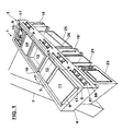
In Fig.1 ist in perspektivischer Darstellung eine derzeit
als besonders bevorzugt angesehene Kücheneinrichtung 1
veranschaulicht, die für eine Wandbefestigung ausgelegt ist,
wobei eine Befestigungswand 2 nur schematisch dargestellt wurde.
Eine solche Wand 2 ist auch in Fig.2 ersichtlich.In Figure 1 is a perspective
Im einzelnen besteht die Kücheneinrichtung 1 gemäß Fig.1 aus
einem Oberteil 3, der durch einen kompakten, dichten, voll verschweißten
Rahmen 4 aus allgemein C-förmigen CrNi-Blechteilen
besteht, vgl. außer Fig.1 auch Fig.2, wo der Querschnitt des
Rahmens 4 sowie auch dessen mittige obere Öffnung 5 ersichtlich
sind. Im einzelnen weist der Rahmen 4 einen Korpus 6 aus vier
auf Gehrung geschnittenen, miteinander dicht verschweißten
Profilen 7 auf, und zwar im einzelnen zwei sich über die gesamte
Länge der Kücheneinrichtung 1 erstreckenden Längs-Profilen 7
(einem vorderen und einem hinteren) sowie zwei sich über die
Tiefe der Kücheneinrichtung 1 erstreckenden Quer-Profilen 7.
Diese Profile 7 sind in den Eckbereichen des Rahmens 4 wie erwähnt
miteinander verschweißt, wie in Fig.1 mit einer
gestrichelten Linie 8 angedeutet ist, wobei insgesamt jedoch ein
homogenes, kompaktes, dichtes, schmutzabweisendes Äußeres des
Korpus 6 des Oberteils 3 erhalten wird.In detail, the
Die Profile 7 sind an ihrer Oberseite mit einer rinnenförmigen
Vertiefung 9 geformt, so daß eine sich rund um die
Öffnung 5 erstreckende Auffangrinne gebildet wird, wie außer aus
Fig.2 insbesondere auch aus Fig.1 hervorgeht. An diese rinnenförmige
Vertiefung 9 schließt innen als Begrenzung der mittigen
Öffnung 5 des Oberteiles 3 eine flanschartige Tragleiste 10 an
(s. Fig.2), die gegebenenfalls am Innenrand nach unten abgewinkelt
sein kann, und die zur Abstützung einer darauf aufgesetzten,
in die Öffnung 5 des Rahmens 3 eingesetzten Arbeitseinheit
dient. Als derartige Arbeitseinheiten sind beispielsweise
in Fig.1 ein Großkochfeld 11, eine Grillplatte 12, eine
Bräterpfanne 13, eine Arbeitsfläche 14 und eine Friteuse 15
veranschaulicht. Selbstverständlich sind auch noch andere -
thermische oder nicht-thermische - Komponenten oder allgemein
Arbeitseinheiten denkbar, wie etwa Warmhalteflächen, Induktions-Kochflachen
usw.; als Kochfelder können insbesondere Ceran-Kochflächen
Verwendung finden, wobei hochglanzpolierte Ober-flächen
vorgesehen werden können, um einem Ansetzen von Speiseresten,
Fett oder allgemein Verschmutzungen entgegenzuwirken.The
Zwischen den einzelnen Arbeitseinheiten 11 bis 15 können
quer verlaufende Zwischenrinnenteile 16 eingesetzt sein, die
vorne und hinten in die umlaufende Ablaufrinne 9 einmünden. In
den vorderen Eckbereichen der Kücheneinrichtung 1 sind weiters
an die Ablaufrinne 9 Abläufe 17 angeschlossen, die, wie
schematisch zusätzlich in Fig.2 angedeutet ist, einfach aus Ablaufrohren
bestehen können, die an der Unterseite frei ausmünden
ober aber bevorzugt mit einer nicht dargestellten Absperreinrichtung
versehen sein können. Unterhalb dieser Abläufe 17 wird
ein verfahrbares, wagenartiges Sammelbehälter- Modul 18 eingeschoben,
s. außer Fig.1 auch Fig.8. Dieses Sammelbehälter-Modul
besteht beispielsweise - gemäß Fig.8 - aus einem Wagen mit
Rädern oder Rollen 19, auf dem mehrere, z.B. drei, Sammelbehälter
20, 21, 22 für die getrennte Sammlung und Entsorgung von
festen Küchenabfällen; Fleischresten; sowie Fetten bzw. Wasser
(Spülwasser) bzw. überlaufendem Kochgut - vorzugsweise abnehmbar
- vorgesehen sind.Between the
Dieses Sammelbehälter-Modul 18 stellt eines von mehreren
möglichen Unterbau-Modulen für die Kücheneinrichtung 1 dar,
wobei in Fig.1 ein weiteres verfahrbares Sammelbehälter-Modul
18' in einer Außerbetriebsstellung eingeschoben gezeigt ist.
Überdies sind als Unterbau-Module, und zwar mit Aufhängung am
Oberteil 3, beispielsweise ein Backrohr-Modul 23, ein offenes
Schrankelement-Modul 24 sowie ein offenes Schrankelement-Modul
25 mit Zwischenbord 26 veranschaulicht. Denkbar sind jedoch auch
(nicht dargestellt) Schrankelemente mit Flügeltüren sowie Ladenelemente,
auch Kühlschrank-Module und dergl. mehr. Insbesondere
könnte das Backrohr-Modul 23 auch ein verfahrbares Modul, mit
Rädern oder Rollen, ähnlich den Sammelbehälter-Modulen 18, 18',
sein. Bevorzugt werden jedoch auf- bzw. einhängbare Unterbau-Module,
wobei diese lösbare Aufhäng-Anbringung nachstehend
anhand insbesondere der Fig.2 erläutert werden soll.This collecting
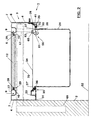
In Fig.2 ist als Beispiel das an der Vorderseite offene
Schrankelement 24 als Unterbau-Modul veranschaulicht, welches an
der Unterseite des Oberteils 3, d.h. des Rahmens 4, aufgehängt
wird, wobei ein Lösen auf einfache Weise, ohne Zuhilfenahme von
besonderen Werkzeugen, möglich ist; auf diese Weise kann die
Reihung von Unterbau-Modulen, z.B. 23, 24, 25 gemäß Fig.1, bei
der jeweiligen Kücheneinrichtung 1 individuell gestaltet werden.
Überdies kann durch Aushängen und Wegnahme dieser Unterbau-Module
auch bequem Zugang zur Unterseite des Oberteils 3 geschaffen
werden, wobei demgemäß die Befestigung der Arbeitseinheiten
11 bis 15 im Rahmen 4 des Oberteils 3 von der Unterseite
her vorgenommen werden kann und wird. Insbesondere werden, wie
beispielsweise in Fig.2 gezeigt ist, zwischen den Tragleisten 10
und Abstufungen 27, Rändern oder gegebenenfalls umgebogenen
Flanschen der Arbeitseinheiten (gemäß Fig.2 z.B. der Grillplatte
12) Dichtungen 28 (Teflon-Dichtungen) eingelegt, und es erfolgt
eine Verschraubung in diesem Bereich von der Unterseite her, wie
in Fig.2 schematisch bei 29 angedeutet ist. Der Zugang für diese
Verschraubung bei 29 ist dabei durch die untere Rahmenöffnung,
zwischen unteren, gegebenenfalls verschieden breiten Flanschen
30 bzw. 31 der (Längs-)Profile 7 des Rahmens 4, möglich.In Fig.2 is an example of the open at the
In diese untere Rahmenöffnung werden wie erwähnt die Unterbau-Module,
z.B. ein Schrank-Modul 24 gemäß Fig.2, eingehängt,
wobei sie von den Flanschen 30, 31 der Rahmenprofile 7 getragen
werden. Im einzelnen sind auf diese Flanschen 30, 31 abgewinkelte
Schienen 32, 33 aufgeschweißt, auf denen auch an der Oberseite
eine Abdeckung 34 angebracht und festgeschraubt werden
kann, wie dies bei 35 veranschaulicht ist. Dabei kann ebenfalls
eine (Teflon-)Dichtung 28 zwischengelegt sein. As mentioned, the substructure modules,
e.g. a
Die Schienen 32, 33 definieren untere Auflageflächen 36 für
flanschartige Aufhäng-Vorsprünge 37, 37' an den oberen Längsrändern
des Unterbau-Moduls 24, s. außer Fig.2 insbesondere auch
Fig.3. Dabei ist aus Fig.3 ersichtlich, daß das Schrank-Modul 24
abgesehen von dem durch eine Winkelleiste gebildeten vorderen
Aufhäng-Vorsprung 37, an der Vorderseite 38 wie auch an der
Oberseite 39 offen ist.The
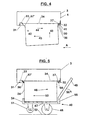
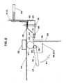
Nachstehend soll nun anhand der Fig.4 und 5 das Einhängen
(Fig.4) bzw. Aushängen (Fig.5) eines solchen Moduls 24 am Rahmen
4 des Oberteils 3 erläutert werden, wobei in Fig.5 überdies ein
bevorzugt bei diesem Einhängen und Aushängen zu verwendender
Wagen 40 veranschaulicht ist.In the following, the hooking-in is now to be carried out using FIGS
(Fig.4) or unhooking (Fig.5) of such a
Wie aus Fig.4 und 5 sowie auch aus Fig.2 hervorgeht, ist die
Breite der Öffnung an der Unterseite des Oberteils 3, d.h. der
Abstand zwischen den einander zugewandten Rändern der Flanschen
30, 31 bzw. Schienen 32, 33, größer als die Tiefe des eigentlichen
Korpus 24' des einzuhängenden Moduls 24, jedoch kleiner
als der Abstand zwischen den voneinander abgewandten Rändern der
Aufhäng-Vorsprünge 37, 37' des Unterbau-Moduls 24. Dadurch kann
das Unterbau-Modul 24 mit seinen Aufhäng-Vorsprüngen 37, 37' auf
den Auflageflächen 36 aufliegen und dabei an benachbarte Abwinkelungen
der Schienen 32, 33 anstoßen, das Unterbau-Modul 24
kann jedoch zum Einhängen bzw. Aushängen etwas schräggestellt
und in der Art eines "Einfädelns" bzw. "Ausfädelns" durch die
Öffnung zwischen den einander zugewandten Rändern der Flanschen
30, 31 hindurchgeführt werden. Dieses Kippen oder Schrägstellen
des Unterbau-Moduls 24 wird durch einen schrägen Übergang 41 der
vorderen Schiene 32 erleichtert; dieser schräge Übergang 41 in
Form einer Schrägrampe führt den vorderen Aufhäng-Vorsprung 37
des Unterbau-Moduls 24 beim Vorziehen desselben, wobei es zu
einem Kippen und Anheben der Vorderseite kommt; durch dieses
Bewegen nach vorne (in Fig.2 nach rechts) und schräg aufwärts
kann dann der hintere Aufhäng-Vorsprung 37' (der ebenfalls in
Form einer Winkelschiene, jedoch mit einer Anschlag-Abwinkelung
vertikal nach oben ausgebildet ist) am Rand des hinteren
Flansches 31 bzw. der hinteren Schiene 33 vorbeibewegt werden,
um das Ein- oder Aushängen zu bewerkstelligen.As can be seen from FIGS. 4 and 5 and also from FIG
Width of the opening on the underside of the
In Fig.4 ist schematisch eine Position des Unterbau-Moduls
24 gezeigt, in dem der vordere Einhäng-Vorsprung 37 den schrägen
Übergang 41 nach oben geführt werden ist, so daß zum Einhängen
des Moduls 24 in der unteren Öffnung des Rahmens 4 der hintere
Aufhäng-Vorsprung 37' am hinteren Flansch 31 vorbeigeführt
werden kann, wie dies mit dem Pfeil 42 veranschaulicht ist.
Zuvor wurde, gemäß Pfeil A, das Modul 24, beispielsweise mit
Hilfe des Wagens 40 gemäß Fig.5, unter dem Oberbau 3 herangeführt
und sodann angehoben, wie mit dem Pfeil 43 veranschaulicht
ist; weiters wurde wie beschrieben die Vorderseite des Unterbau-Moduls
24 geringfügig nach vorne bewegt, s. Pfeil 44, wobei der
vordere Aufhäng-Vorsprung 37 am Übergang 41 schräg nach vorne
oben geführt wurde.A position of the substructure module is shown schematically in FIG
24, in which the front hook-in
Wenn das Unterbau-Modul 24 gemäß Pfeil 42 auch am hinteren
Ende genügend angehoben wurde (wobei die Abdeckung 34 auch als
Anschlag hierfür dient), kann das Unterbau-Modul 24 mit einer
leichten Bewegung nach hinten (s. Pfeil 45) endgültig auf den
Schienen 32, 33, d.h. auf deren Auflageflächen 36, aufgehängt
werden.If the
Beim Aushängen des Unterbau-Moduls 24 wird im wesentlichen
umgekehrt wie beim Einhängen vorgegangen, wobei einleitend, s.
Fig.5, das Modul 24 gemäß Pfeil 46 mit Hilfe des Wagens 40 nach
vorne gezogen wird, nachdem der Wagen 40 mit seiner Auflagefläche
47 gegen die Unterseite des Moduls 24 durch Kippen um
sein größeres Rad 48 mit Hilfe eines Handbügels 49, der einen
Kipphebel hierfür bildet, in Richtung des Pfeiles 50 gekippt
wurde, wobei das kleinere Rad 51 vom Boden 52 abgehoben wurde.
Nach der beschriebenen Bewegung des Moduls 24 nach vorne, in
Richtung des Pfeiles 46, wobei der vordere Aufhäng-Vorsprung 37
am schrägen Übergang 41 hochgleitet, kommt der hintere Aufhäng-Vorsprung
37' vom hinteren Flansch 31 und der hinteren Auflagefläche
36 frei, wodurch das Modul 24 an der Rückseite aus der
Rahmenöffnung nach unten fällt, wenn der Wagen 40 mit seiner
kleineren Rolle 51 abgesenkt wird. Hierbei oder danach wird der
Wagen 40 mit dem Modul 24 in Richtung des Pfeils 53 nach hinten
geschoben, so daß der vordere Aufhäng-Vorsprung 37 vorne von der
Schiene 32 frei kommt, wodurch die Aushängung zu Ende geführt
ist.When the
Wie aus Fig.5 weiters ersichtlich ist, besitzt der Wagen 40
an den beiden Enden seiner Auflagefläche 47 hochstehende Ränder
54, 55, um so das einzuhängende bzw. auszuhängende Unterbau-Modul
24 beim Kippen nach vorne bzw. hinten gegen ein Abrutschen
zu sichern. Seitlich ist die Auflagefläche 47 frei, so daß mit
ein und demselben Wagen 40 Unterbau-Module mit den verschiedensten
Breiten (s. beispielsweise die Module 24, 25 in Fig.1)
eingehängt bzw. ausgehängt werden können. Es sei auch erwähnt,
daß die Auflagefläche 47 sowie die Ränder 54, 55 nicht homogene,
plattenförmige Teile sein müssen, sondern auch durch
gitterartige oder rostartige Strukturen gebildet sein können.
Insbesondere können auch die Ränder 54, 55 durch bügelförmig
gebogene Stangen erhalten sein. Wesentlich ist nur, daß der
Kipphebel 49 (Griffbügel) fest mit der Auflagefläche 47 verbunden
ist, wobei die Stabilität ausreichen muß, um die größten,
d.h. schwersten, Unterbau-Module ein- und aushängen zu können.As can also be seen from FIG. 5, the
Um nach dem Einsetzen ein ungewolltes Verschieben der
Unterbau-Module, z.B. 24, nicht nur in Längsrichtung der
Schienen 32, 33, sondern vor allem auch quer dazu, also insbesondere
gemäß der Darstellung in Fig.2 nach rechts (nach vorne),
zu verhindern, ist im vorderen oberen Bereich des jeweiligen
Unterbau-Moduls, z.B. 24, benachbart dem Aufhäng-Vorsprung 37,
ein Arretierteil 56 in Form eines Arretierhebels angebracht, der
in an einer den Aufhäng-Vorsprung 37 mit ihrem oberen,
horizontalen Flansch definierenden Winkelprofilleiste innen
angeschweißten Laschen 57, 58 (s. außer Fig.6 insbesondere auch
Fig.7), und zwar in nach oben offenen, im übrigen kreisbogenförmigen
Lagerausnehmungen 59, mit einem Stangenteil 60 schwenkbar
gelagert ist. Der Stangenteil 60 ist zu einem Griffbügel 61
komplettiert, der den einen Hebelarm des Arretierhebels 56 bildet.
Der andere Hebelarm 62 wird durch einen gegen die Abdeckung
34 des Oberteils 3 verspreizbaren Rohrkörper 63 gebildet. Dieser
Rohrkörper 63 liegt in der in Fig.6 gezeigten Arretierstellung
oder Blockierstellung einerseits an der Oberkante des Korpus des
Unterbau-Moduls 24 und andererseits an der Unterseite der Abdeckung
34 an, und zwar in einer "Übertotpunktlage", aus der er
durch Verschwenken des mit ihm fest verbundenen Handgriffes 61
in Pfeilrichtung 64 (s.Fig.6) - unter geringfügiger elastischer
Auslenkung der Abdeckung 34 nach oben - in eine Freigabestellung
bewegt werden kann. Als Versteifung bei diesem Verspreizen des
Arretierhebels 56 gegen die Abdeckung 34 ist auf dieser ein im
Querschnitt rechteckiges Versteifungs-Formrohr 65 aufgeschweißt. To prevent the inadvertent shifting after insertion
Substructure modules, e.g. 24, not only in the longitudinal direction of the
Wie weiters aus Fig.6 ersichtlich ist, ist die als Aufhängteil
vorgesehene abgewinkelte Schiene 32 an der Vorderseite nach
oben hochgezogen, um als Verstärkung beim Anschrauben eines
Begrenzungs- bzw. Schutzbügels 66 zu dienen, der - s. auch Fig.1
- zur Begrenzung und als Rammschutz eines Bedienfeldes mit
Betätigungsgriffen oder dergl. Bedienelementen 67 dient. Selbstverständlich
können anstatt von vorstehenden knopfartigen
Betätigungsgriffen auch z.B. Tast- bzw. Sensorfelder als Bedienelemente
für die Arbeitseinheiten 11 bis 15 vorgesehen sein.As can also be seen from FIG. 6, it is a suspension part
provided
Im übrigen sind die durch die abgewinkelten Schienen 32, 33
sowie die Rahmen-Profile 7 begrenzten Hohlräume (z.B. 68 in
Fig.6) an den Stirnseiten durch die sich in Querrichtung erstreckenden
äußeren Quer-Profile 7 abgedeckt, wobei dort ebenfalls
eine Verschweißung vorgenommen sein kann, so daß insgesamt
auch hier zur Umgebung hin in Verbindung stehende, jedoch für
eine Reinigung schwer zugängliche und so ein Hygienerisiko
darstellende Hohlräume vermieden sind.Otherwise, the through the angled rails 32, 33rd
as well as the frame profiles 7 limited cavities (e.g. 68 in
Fig.6) on the end faces by the extending in the transverse direction
outer
Insgesamt weist die beschriebene Kücheneinrichtung 1 somit
einen homogenen, kompakten, fugenlosen Oberteil 3 auf, der
leicht zu reinigen ist, und der auch von vorneherein wenig Möglichkeit
für ein Ansetzen von Speiseresten und dergl. bietet, so
daß ein hohes Ausmaß an Hygiene gewährleistet wird. Weiters ist
durch das beschriebene modulare System betreffend Arbeitseinheiten
sowie Unterbauten ein hohes Maß an Flexibilität für
individuelle Gestaltungen gegeben.Overall, the
Wie schließlich noch schematisch in Fig.2 gezeigt ist, kann
in der Wand 2 ein Träger 69 eingemauert sein, von dem
horizontale Schienen 70 für die Befestigung (und Justierung) des
Oberteils 3 der Kücheneinrichtung 1 nach außen abstehen, und
zwar bevorzugt an den äußeren Rändern der Kücheinrichtung 1.
Demgemäß ist die gesamte Kücheneinrichtung 1 an der Wand zu befestigen,
wobei unterhalb der aufgehängten Unterbau-Module, z.B.
24, Bodenfreiheit gegeben ist. Gegebenenfalls können jedoch
auch, sollte dies erwünscht sein, an den äußeren Rändern oder
Breitseiten der Kücheneinrichtung 1 in an sich herkömmlicher
Weise Steher angebracht sind, um die Kücheneinrichtung 1 auf dem
Boden abzustützen, sollte eine Wandbefestigung nicht möglich
sein.Finally, as shown schematically in FIG
be walled in the wall 2 a
Die Profile 7 für den Rahmen 4 des Oberteiles 3 bestehen
vorzugsweise aus einem 3 mm-CrNi-Blech, wogegen die Unterbau-Module,
z.B. 24, 25, aus einem 2 mm-CrNi-Blech bestehen können.The
Die beschriebene Kücheneinrichtung 1 eignet sich insbesondere
für sog. "Profi"küchen oder Großküchen, etwa für
Spitäler oder Restaurants, wo strenge Hygienevorschriften zu
erfüllen sind, und wo auch ein hohes Ausmaß an Mobilität bzw.
Variabilität der einzelnen Unterbauten wie auch Arbeitseinheiten
erwünscht ist. Aus den vorstehenden Erläuterungen ergibt sich,
daß insbesondere die Unterbau-Module ganz einfach eingehängt,
entlang der Schienen 32, 33 über die gesamte Länge der
Kücheneinrichtung 1 verschoben und mit Hilfe des Arretierhebels
56 fixiert werden können, und daß auch die Arbeitseinheiten 11
bis 15 von der Unterseite her einfach gelöst, abgenommen, an
anderer Stelle eingesetzt und wieder fixiert werden können.The
Claims (14)
- A kitchen equipment having a rectangular top part (3) with an opening (5) into which at least one working unit (11 to 15) is releasably inserted and with at least one suspendedly fastened substructure (e.g. 24), characterized in that the top part (3) is a frame corpus (6) of generally C-shaped metal sections (7) tightly welded together at the frame corners (8), which forms an outwardly gap-free frame (4) having a central opening (5) for insertion of the working unit(s) (11 to 15), suspension members being provided on the lower side of the frame (4), adjacent the opening (5), for detachable suspension of the module-like substructure (e.g. 24) thereon.
- A kitchen equipment according to claim 1, characterized in that the frame (4) on its upper side has a channel-shaped indentation (9) extending around the central opening (5).
- A kitchen equipment according to claim 2, characterized in that at least one downwardly extending drain (17) is connected to the channel-shaped indentation (9).
- A kitchen equipment according to claim 3, characterized in that below the drain (17) a preferably movable collecting container module (18; 18') is provided as substructure.
- A kitchen equipment according to any one of claims 1 to 4, characterized in that the (respective) working unit (11 to 15) comprising optionally bent, flange-like rims (27) is put onto carrying ledges (10) defining the central opening (5) and screwed to these carrying ledges (10) with gaskets (28) interposed.
- A kitchen equipment according to any one of claims 1 to 5, characterized in that the suspension members are formed by angled rails (32, 33) and the substructure module (24) has flange-like suspension projections (37).
- A kitchen equipment according to claim 6, characterized in that the one rail (32) includes a transition (41) leading inclinedly upwardly from a resting surface (36).
- A kitchen equipment according to claim 6 or 7, characterized in that the distance between facing rims of the rails (32, 33) is smaller than the front-to-rear dimension or depth of the substructure module (24), measured between the facing away rims of the suspension projections (27), yet is larger than the depth of the corpus of the substructure module (24), the respective substructure module (24) in its suspended state abutting with its suspension projections (37) on angled portions (e.g. 41) which delimit resting surfaces (36) of the rails (32, 33) on which the suspension projections (37) rest.
- A kitchen equipment according to any one of claims 1 to 8, characterized in that the substructure module (24) at its upper, front-side rim region includes a locking member (56) cooperating with the top part (3) to lock the substructure module (24) on the top part (3) in its suspended state.
- A kitchen equipment according to claims 8 and 9, characterized in that the locking member is formed by a locking lever (56) having a lever arm (62) braceable relative to the top part (3).
- A kitchen equipment according to any one of claims 1 to 10, characterized in that the substructure module (24) is designed to be upwardly open.
- A kitchen equipment according to any one of claims 1 to 11, characterized in that the top part frame (4) is designed for a mere fastening to the wall.
- A kitchen equipment according to any one of claims 1 to 12, characterized in that the top part frame (4) consists of a CrNi sheet, e.g. having a thickness of approximately 3 mm.
- A kitchen equipment according to any one of claims 1 to 13, characterized in that the corpus of the substructure module (24) consists of a CrNi sheet, e.g. having a thickness of approximately 2 mm.
Priority Applications (1)
| Application Number | Priority Date | Filing Date | Title |
|---|---|---|---|
| AT97942700T ATE237975T1 (en) | 1996-11-08 | 1997-10-13 | KITCHEN EQUIPMENT WITH TOP PART AND AT LEAST ONE BASE, AND TROLLEY FOR HANGING AND UNHANGING A BASE MODULE FROM A TOP PART |
Applications Claiming Priority (4)
| Application Number | Priority Date | Filing Date | Title |
|---|---|---|---|
| AT65696 | 1996-11-08 | ||
| AT65696U AT1702U1 (en) | 1996-11-08 | 1996-11-08 | KITCHEN EQUIPMENT |
| AT65696U | 1996-11-08 | ||
| PCT/AT1997/000217 WO1998020776A1 (en) | 1996-11-08 | 1997-10-13 | Kitchen arrangement with a top part and at least one substructure, carriage for removably suspending a substructure module from the top part |
Publications (2)
| Publication Number | Publication Date |
|---|---|
| EP1011380A1 EP1011380A1 (en) | 2000-06-28 |
| EP1011380B1 true EP1011380B1 (en) | 2003-04-23 |
Family
ID=3496367
Family Applications (1)
| Application Number | Title | Priority Date | Filing Date |
|---|---|---|---|
| EP97942700A Expired - Lifetime EP1011380B1 (en) | 1996-11-08 | 1997-10-13 | Kitchen arrangement with a top part and at least one substructure, carriage for removably suspending a substructure module from the top part |
Country Status (7)
| Country | Link |
|---|---|
| EP (1) | EP1011380B1 (en) |
| AT (1) | AT1702U1 (en) |
| AU (1) | AU4444697A (en) |
| DE (2) | DE59709934D1 (en) |
| PL (1) | PL334874A1 (en) |
| WO (1) | WO1998020776A1 (en) |
| YU (1) | YU21699A (en) |
Families Citing this family (6)
| Publication number | Priority date | Publication date | Assignee | Title |
|---|---|---|---|---|
| NL1012371C2 (en) * | 1999-06-16 | 2000-12-19 | Holec Holland Nv | Sink kitchen cabinet with sub-distribution. |
| WO2009050091A2 (en) * | 2007-10-12 | 2009-04-23 | BSH Bosch und Siemens Hausgeräte GmbH | Cooking hob in particular a gas cooking hob |
| SE535103C2 (en) * | 2009-11-13 | 2012-04-17 | Elektrotermo Ab | Bench arrangement for cabinets |
| DE102011115109B4 (en) * | 2011-10-07 | 2016-09-01 | Claudia Musch | Mobile kitchen device |
| WO2017025919A2 (en) | 2015-08-10 | 2017-02-16 | Duke Manufacturing Co. | Food serving station and associated appliances and methods |
| WO2022173388A1 (en) * | 2021-02-15 | 2022-08-18 | Efendi Proje Mimarlik Muhendislik Sanayi Ve Ticaret Limited Sirketi | A modular workstation |
Family Cites Families (11)
| Publication number | Priority date | Publication date | Assignee | Title |
|---|---|---|---|---|
| SE194849C1 (en) * | ||||
| US3746416A (en) * | 1971-07-01 | 1973-07-17 | Gen Electric | Modular furniture system and means for manipulating and connecting components thereof |
| DE2407582C3 (en) * | 1974-02-16 | 1981-02-26 | Licentia Patent-Verwaltungs-Gmbh, 6000 Frankfurt | Built-in hob made of glass or the like. with several individual cooking zones for fitted kitchen furniture |
| DE2917144A1 (en) * | 1979-04-27 | 1980-11-06 | Schwarzwaelder Kuechenmoebelwe | WORKTOP FOR BUILT-IN KITCHEN WITH A RECESSED INSTALLATION COMPONENT AND METHOD FOR PRODUCING SUCH A WORKTOP |
| US4562827A (en) * | 1984-11-21 | 1986-01-07 | Roper Corporation | Downdraft countertop cooking range |
| DE3730901A1 (en) * | 1987-09-15 | 1989-03-23 | Schock & Co Gmbh | TABLE TOP WITH INSERTED MOLDED PART |
| FR2644047B1 (en) * | 1989-03-10 | 1992-05-15 | Barthelemy Auffray | KITCHEN FURNITURE |
| NL9002266A (en) * | 1990-10-18 | 1992-05-18 | Ahrend Groep Nv | STORAGE CABINET PROVIDED WITH WHEELS OR ROLLERS. |
| DE4034250A1 (en) * | 1990-10-27 | 1992-04-30 | Juno Grosskuechen | CONNECTING DEVICE FOR SUPPORTING KITCHEN EQUIPMENT |
| DE4306545C1 (en) * | 1993-03-03 | 1994-04-21 | Neubauer Kurt Maschf | Kitchen with adjacent interconnected work units - has grease collector channel at connecting point, fitting into gap formed by angled top edges |
| ES2078160B1 (en) * | 1993-11-08 | 1998-06-16 | Fagor S Coop | PROVISION OF COMMERCIAL COOKING MODULES. |
-
1996
- 1996-11-08 AT AT65696U patent/AT1702U1/en not_active IP Right Cessation
-
1997
- 1997-10-13 YU YU21699A patent/YU21699A/en unknown
- 1997-10-13 DE DE59709934T patent/DE59709934D1/en not_active Expired - Fee Related
- 1997-10-13 EP EP97942700A patent/EP1011380B1/en not_active Expired - Lifetime
- 1997-10-13 WO PCT/AT1997/000217 patent/WO1998020776A1/en not_active Application Discontinuation
- 1997-10-13 DE DE19781256T patent/DE19781256D2/en not_active Ceased
- 1997-10-13 PL PL97334874A patent/PL334874A1/en unknown
- 1997-10-13 AU AU44446/97A patent/AU4444697A/en not_active Abandoned
Also Published As
| Publication number | Publication date |
|---|---|
| PL334874A1 (en) | 2000-03-27 |
| YU21699A (en) | 2000-03-21 |
| DE59709934D1 (en) | 2003-05-28 |
| DE19781256D2 (en) | 2000-08-03 |
| EP1011380A1 (en) | 2000-06-28 |
| WO1998020776A1 (en) | 1998-05-22 |
| AU4444697A (en) | 1998-06-03 |
| AT1702U1 (en) | 1997-10-27 |
Similar Documents
| Publication | Publication Date | Title |
|---|---|---|
| EP1306622B1 (en) | Track system for food support in a baking oven | |
| EP1136392A2 (en) | Drawer for a cabinet, in particular a kitchen cabinet, for supporting waste receptacles | |
| DE2206904A1 (en) | Cooker hood | |
| EP1011380B1 (en) | Kitchen arrangement with a top part and at least one substructure, carriage for removably suspending a substructure module from the top part | |
| DE19515080C2 (en) | Barbecue especially with charcoal firing | |
| EP2128529B1 (en) | Oven muffle | |
| WO1996029549A1 (en) | Device for condensate removal with separators | |
| DE4446757C3 (en) | Baking and roasting oven with a telescopic trolley | |
| DE102011115109B4 (en) | Mobile kitchen device | |
| DE3128944C2 (en) | Support rack for a stove with baking and roasting space | |
| EP2284447B1 (en) | Muffle for baking oven | |
| DE69815896T2 (en) | TRAY FOR CARRYING ITEMS, ESPECIALLY FOR REFRIGERATORS | |
| EP1376019A1 (en) | Muffle for baking oven | |
| DE10241489A1 (en) | Telescopic system and pull-out for a food rack | |
| DE202015105748U1 (en) | Mounting frame for a table-top cooker | |
| DE102005033530B4 (en) | Edge limitation for cover plate of an extractor hood and extractor hood | |
| DE202005012053U1 (en) | Vapour hood for food oven is fabricated of a net or textile fabric forming meandering passages to outlet | |
| DE8020612U1 (en) | CAKE TIN | |
| DE3602454C2 (en) | ||
| DE202007009433U1 (en) | Mobile kitchen | |
| EP1376017A1 (en) | Telescopic system and drawer for food support | |
| DE10062116C2 (en) | oven | |
| DE202023105906U1 (en) | Mobile kitchen, replacement work surface and kitchen rack | |
| DE202013003343U1 (en) | Raclette machine | |
| DE10054404C1 (en) | Device, to connect two adjacent kitchen appliances, has connection strip that extends along joint between appliances and secures side projections of cover plates that cover appliances |
Legal Events
| Date | Code | Title | Description |
|---|---|---|---|
| PUAI | Public reference made under article 153(3) epc to a published international application that has entered the european phase |
Free format text: ORIGINAL CODE: 0009012 |
|
| 17P | Request for examination filed |
Effective date: 19990504 |
|
| AK | Designated contracting states |
Kind code of ref document: A1 Designated state(s): AT BE CH DE DK FI FR GR IT LI NL SE |
|
| AX | Request for extension of the european patent |
Free format text: SI PAYMENT 19990505 |
|
| 17Q | First examination report despatched |
Effective date: 20010710 |
|
| RAP1 | Party data changed (applicant data changed or rights of an application transferred) |
Owner name: LOHBERGER, HEIZ + KOCHGERAETE-TECHNOLOGIE GMBH |
|
| GRAH | Despatch of communication of intention to grant a patent |
Free format text: ORIGINAL CODE: EPIDOS IGRA |
|
| GRAH | Despatch of communication of intention to grant a patent |
Free format text: ORIGINAL CODE: EPIDOS IGRA |
|
| GRAA | (expected) grant |
Free format text: ORIGINAL CODE: 0009210 |
|
| AK | Designated contracting states |
Designated state(s): AT BE CH DE DK FI FR GR IT LI NL SE |
|
| AX | Request for extension of the european patent |
Extension state: SI |
|
| PG25 | Lapsed in a contracting state [announced via postgrant information from national office to epo] |
Ref country code: FR Free format text: LAPSE BECAUSE OF FAILURE TO SUBMIT A TRANSLATION OF THE DESCRIPTION OR TO PAY THE FEE WITHIN THE PRESCRIBED TIME-LIMIT Effective date: 20030423 Ref country code: FI Free format text: LAPSE BECAUSE OF FAILURE TO SUBMIT A TRANSLATION OF THE DESCRIPTION OR TO PAY THE FEE WITHIN THE PRESCRIBED TIME-LIMIT Effective date: 20030423 |
|
| RAX | Requested extension states of the european patent have changed |
Extension state: SI Payment date: 19990504 |
|
| RIN1 | Information on inventor provided before grant (corrected) |
Inventor name: MARCHHART, WOLFGANG |
|
| REG | Reference to a national code |
Ref country code: CH Ref legal event code: EP |
|
| REF | Corresponds to: |
Ref document number: 59709934 Country of ref document: DE Date of ref document: 20030528 Kind code of ref document: P |
|
| REG | Reference to a national code |
Ref country code: CH Ref legal event code: NV Representative=s name: SPIERENBURG & PARTNER AG, PATENT- UND MARKENANWAEL |
|
| PG25 | Lapsed in a contracting state [announced via postgrant information from national office to epo] |
Ref country code: SE Free format text: LAPSE BECAUSE OF FAILURE TO SUBMIT A TRANSLATION OF THE DESCRIPTION OR TO PAY THE FEE WITHIN THE PRESCRIBED TIME-LIMIT Effective date: 20030723 Ref country code: GR Free format text: LAPSE BECAUSE OF FAILURE TO SUBMIT A TRANSLATION OF THE DESCRIPTION OR TO PAY THE FEE WITHIN THE PRESCRIBED TIME-LIMIT Effective date: 20030723 Ref country code: DK Free format text: LAPSE BECAUSE OF FAILURE TO SUBMIT A TRANSLATION OF THE DESCRIPTION OR TO PAY THE FEE WITHIN THE PRESCRIBED TIME-LIMIT Effective date: 20030723 |
|
| PG25 | Lapsed in a contracting state [announced via postgrant information from national office to epo] |
Ref country code: LI Free format text: LAPSE BECAUSE OF NON-PAYMENT OF DUE FEES Effective date: 20031031 Ref country code: CH Free format text: LAPSE BECAUSE OF NON-PAYMENT OF DUE FEES Effective date: 20031031 Ref country code: BE Free format text: LAPSE BECAUSE OF NON-PAYMENT OF DUE FEES Effective date: 20031031 |
|
| PLBE | No opposition filed within time limit |
Free format text: ORIGINAL CODE: 0009261 |
|
| STAA | Information on the status of an ep patent application or granted ep patent |
Free format text: STATUS: NO OPPOSITION FILED WITHIN TIME LIMIT |
|
| 26N | No opposition filed |
Effective date: 20040126 |
|
| EN | Fr: translation not filed | ||
| BERE | Be: lapsed |
Owner name: *LOHBERGER HEIZ + KOCHGERATE-TECHNOLOGIE G.M.B.H. Effective date: 20031031 |
|
| PG25 | Lapsed in a contracting state [announced via postgrant information from national office to epo] |
Ref country code: NL Free format text: LAPSE BECAUSE OF NON-PAYMENT OF DUE FEES Effective date: 20040501 |
|
| REG | Reference to a national code |
Ref country code: CH Ref legal event code: PL |
|
| NLV4 | Nl: lapsed or anulled due to non-payment of the annual fee |
Effective date: 20040501 |
|
| PGFP | Annual fee paid to national office [announced via postgrant information from national office to epo] |
Ref country code: AT Payment date: 20041021 Year of fee payment: 8 |
|
| PGFP | Annual fee paid to national office [announced via postgrant information from national office to epo] |
Ref country code: DE Payment date: 20041029 Year of fee payment: 8 |
|
| PG25 | Lapsed in a contracting state [announced via postgrant information from national office to epo] |
Ref country code: IT Free format text: LAPSE BECAUSE OF NON-PAYMENT OF DUE FEES Effective date: 20051013 Ref country code: AT Free format text: LAPSE BECAUSE OF NON-PAYMENT OF DUE FEES Effective date: 20051013 |
|
| PG25 | Lapsed in a contracting state [announced via postgrant information from national office to epo] |
Ref country code: DE Free format text: LAPSE BECAUSE OF NON-PAYMENT OF DUE FEES Effective date: 20060503 |