EP1136392A2 - Drawer for a cabinet, in particular a kitchen cabinet, for supporting waste receptacles - Google Patents
Drawer for a cabinet, in particular a kitchen cabinet, for supporting waste receptacles Download PDFInfo
- Publication number
- EP1136392A2 EP1136392A2 EP01107057A EP01107057A EP1136392A2 EP 1136392 A2 EP1136392 A2 EP 1136392A2 EP 01107057 A EP01107057 A EP 01107057A EP 01107057 A EP01107057 A EP 01107057A EP 1136392 A2 EP1136392 A2 EP 1136392A2
- Authority
- EP
- European Patent Office
- Prior art keywords
- cabinet
- drawer
- particular according
- hanging frame
- profile
- Prior art date
- Legal status (The legal status is an assumption and is not a legal conclusion. Google has not performed a legal analysis and makes no representation as to the accuracy of the status listed.)
- Granted
Links
Images


Classifications
-
- B—PERFORMING OPERATIONS; TRANSPORTING
- B65—CONVEYING; PACKING; STORING; HANDLING THIN OR FILAMENTARY MATERIAL
- B65F—GATHERING OR REMOVAL OF DOMESTIC OR LIKE REFUSE
- B65F1/00—Refuse receptacles; Accessories therefor
- B65F1/14—Other constructional features; Accessories
- B65F1/1426—Housings, cabinets or enclosures for refuse receptacles
-
- A—HUMAN NECESSITIES
- A47—FURNITURE; DOMESTIC ARTICLES OR APPLIANCES; COFFEE MILLS; SPICE MILLS; SUCTION CLEANERS IN GENERAL
- A47B—TABLES; DESKS; OFFICE FURNITURE; CABINETS; DRAWERS; GENERAL DETAILS OF FURNITURE
- A47B77/00—Kitchen cabinets
- A47B77/04—Provision for particular uses of compartments or other parts ; Compartments moving up and down, revolving parts
- A47B77/18—Provision for particular uses of compartments or other parts ; Compartments moving up and down, revolving parts by special arrangements for accommodating removable containers
Definitions
- the invention relates to a in a closet included drawer, especially kitchen cupboard drawer, with telescopic slide rails, each consisting from a fixed rail and a moving one Rail, with a longitudinal mounting bracket on the moving rail is attached and the longitudinal mounting bracket on the end face through end plates to one Frame construction are supplemented.
- the object of the invention is a generic Cupboard drawer using existing structural Advantageously to further develop conditions; so it should Another function opened at the bottom of the cabinet drawer become.
- the hanging frame is supported by a U-profile that with its U opening directed outwards on the frame Longitudinal mounting bracket is arranged.
- the U-bridge circumscribes on this longitudinal area in a closed manner the opening of the hanging frame; that makes it easier Care and reduces the risk of injury appropriate care handling.
- the longitudinal mounting bracket is in the area extend below the rails. It is from Advantage if the U-profile is based on a longitudinal mounting bracket is arranged.
- the hanging frame seen in cross section, L-shaped. It is also provided that the hanging frame, at least on its long sides, one with one Covering the rails interacting sealing profile is.
- One made of rubber or rubber-like material Existing sealing profile provides a particularly easy to fit Connection to the surrounding area d.
- the closet wall units has, provided that on an inside of a A wall is arranged a support that a loosely insertable lid. It forms one Waste hold-down and possibly even an odor trap and is itself secured against displacement. To the It can be easily removed for cleaning.
- the fixed rail is attached to the wall unit, preferably directly Assignment.
- a Leg of the substantially U-shaped in cross section Cover the rails with the traveling rail connected is. This leads to a closed box profile, again stiffening the management area.
- the leg closing the box profile is a leg of the cover on the wall of the cabinet. Ends here an inside thigh with its U opening downward-facing cover below the hanging frame. An alignment has been made in accordance with the end of the inside leg into the U opening of the U-profile points. On the other hand, it can also be proceeded so that the inside leg Part of one in front of the opening of the waste bin Throw-in funnel.
- the enlarged funnel opening has an introductory effect on waste, for example not precise, d. H.
- the hanging frame at least on its longitudinal legs, one for Interaction with the longitudinal mounting bracket Has adjustment part. You can use this Frame opening vary, especially a fine adjustment for the safe hanging of the waste container to reach.
- the adjustment part has a horizontal leg Adjustable mounting profile. Acted appropriately it is a strip-shaped with respect to the adjustment part. It is expedient to use a cross-section U-shaped bar used. Their U space leaves make the best use of it, with the U-legs the "meat" for a fastener. It is accordingly advantageous that the adjustment part has a mounting recess has that of the used Crossing of the hanging profile is covered.
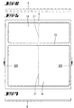
- a kitchen cabinet Inside 1 of a kitchen cabinet 2, in particular A kitchen cabinet is a cupboard drawer 3 added. It is guided horizontally and can be frontally placed in a free board position prefer.
- the rail guide is through on the inside, 4 wall units running in parallel Extending telescopic rails 5 reached.
- the latter exist each from a fixed rail 6 and a moving one Rail 7.
- the telescopic rail 5 can be another Intermediate rail (not shown) can be assigned, if the required extension stroke has a two-part Extending telescopic rail 5 is not sufficient is.
- the fixed rail 6 sits firmly on the inside the respective wall unit 4. This goes to the said Rail 6 in a bracket 8 over. Acts preferentially it is a flange-like strip with fastening openings for screws or the like.
- one of the traveling rails 7 bracket leading to the cabinet drawer 3.
- The consists of a longitudinal mounting bracket 9. Both Long sides of the cabinet drawer 3 are so equipped.
- the two longitudinal mounting brackets 9 are part of one Frame construction. Complementing or closing the frame end plates 10 and 11, 10 are a front end plate and 11 a rear face plate.
- the front faceplate 10 can also be designed to form an aperture with gripping option for the convenient pulling forward of the Cabinet drawer 3 and slide it back in.
- the frame-closing fasteners can be more classic Be kind, i.e. bends with through holes for fastening screws.
- the horizontally aligned longitudinal mounting brackets 9 form the support of a bottomless hanging frame R. the cabinet drawer 3.
- this hanging frame 3 one or more waste containers 12 are freely suspended supported.
- the longitudinal mounting bracket 9 take as shown Embodiment the hanging frame R indirectly on.
- a stabilizing bar profile is interposed, basically a U-profile 13. That is directed out of the frame with its U opening 14. It points towards the inside of the corresponding one Wall unit 4.
- the vertical U-web 15 of the U-profile 13 settles above in a shorter U-leg 16 and below in one longer U-leg 17 continues, so that in concrete embodiment as it were a standing L-profile.
- the upper, shorter U-leg 16 forms the support of the hanging frame R.
- the hanging frame R is implemented like a mounting panel and the support. whose U-profiles 13 plug-in. He sits under tension on the U-bridge 15. He also has an L-profile. It is lying down. The shorter L-profile legs point downwards. He provides the frame opening 18, adapted to the cross section the jacket wall of the waste container 12. The U-web 15 circumscribes to the measure of the thickness of the downward the pointing L-profile leg of the hanging frame R, likewise said jacket wall. The takes a conical shape downwards. It is, as Fig. 1 shows, sufficient hanging play to disposal.
- the hanging support of the waste container 12 provides it edge bead angled outwards and downwards as Support edge 19.
- the gripping of the waste container 12 is done in a known manner Way over foldable bracket 20.
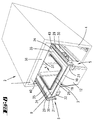
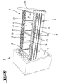
- FIG. 2 removable up to 7.
- the contour of the in the frame opening 18 attachable waste container is in dash-dotted lines Line type shown in Figs. 2 and 5.
- FIG. 2 A twin configuration is implemented in FIG. 2.
- Waste container 12 in the longitudinal direction assigned in a row. They support each other at the common border. It was in this regard the longitudinal center, where for reasons of clarity a somewhat exaggerated gap 21 reproduced is.
- Fig. 5 there is a change in the floor plan insofar as there the hanging frame R two basically has rectangular frame openings 18, each twin.
- the width of a frame is about set to half of the larger frame opening 18.
- the two frame openings 18 of the hanging frame R are separated from one another via an intermediate strut 22.
- the gap 21 is also indicated in this variant, which is so small here that it does not become one significant slipping of the suspended waste containers 12 can come.
- 2 to 7 is also the the L-profile described, stiffening the frame Removable inner bend, labeled 23.
- Such bends 23 are also in the area of the front Face plate 10 and rear face plate 11 made or realizable, as it were as a welcome stiffener functioning and moreover also in terms of attack usable.
- the bends here are on the outside or too Outside.
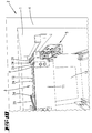
- the longitudinal mounting bracket 9 of the drawer-side, So traveling rail 7 extend in the area below the rails 6, 7.
- the lower, longer U-leg 17 of the U-profile 13 rests on the horizontally angled Longitudinal mounting bracket 9 and is there supported.
- a Rivet 24 It reaches through the overlapping ones Ends of parts 9, 17.
- the longitudinal mounting bracket 9 or the lower U-leg 17 have an elongated hole 25.
- said elongated holes 25 are in the transverse direction to the pull-out direction arrow x of the cabinet drawer 3 extend. This results in an advantageous and at the same time simple adjustment device for determining the Play in this direction regarding the frame opening 18.
- the extendable telescopic rails 5 are based on the usual viewing angle, out of sight. For this serves a top cover 29. It is seen in cross section, practically around U-plate, light approximated a V-profile. That is up in its U-part nicely rounded and forms with a downward directed U-leg distant from the frame opening a kind Cover screen 30. The other, the frame opening 18 closer lying U-leg 31 is in this direction in the frame sloping. He's going into one concave curve over and ends in a striking nose-like Formation 32, normally acts as a hold-down, or additionally a holding groove for the Longitudinal mounting bracket 9 optionally re-assignable Bottom of the cabinet drawer 3.
- This one Board or the like formed floor has the reference numeral 33 and is in dash-dotted line style in Fig. 1 indicated.
- the leg 31 that goes against the U opening 14 is then used in the sense that it became a kind Joint seal is used between the body of the Cover 29 and the hanging frame R.
- Assigned sealing profile 34 To hold the rubber or the like existing sealing profile 34 is used Hanging frame R, specifically the non-angled longitudinal edge the same, so that this as the carrier of the one corresponding plug-in shoe 35 equipped sealing profile 34 can be used.
- the front edge of the upper leg of the plug-in shoe 35 is chamfered on the longitudinal narrow edge, so that there is a sealing lip. in the The back of the shoe 35 sits as seen from above concave, protruding lobe away, the, through slight pre-tensioning is springy and therefore seals well the corresponding wide area of the leg 31 is present. Appropriate grooving avoids this The formation of dirt nests. Rather, it can be bring about a convenient cleaning.
- the corresponding cover bears the reference number 36
- the underside of its cover 37 leaves a certain gap dimension to comb the cover 29 and the top in End plates 10 terminating essentially at the same height and 11. So the cabinet drawer 3 can the Underneath ceiling 37. Acting as an odor trap, a sealing strip can be interposed.
- the lid 36 finds one on the cabinet fastening wall side Support. It has been achieved with the participation of his Cross-sectional shape. It is U-shaped. The U-bridge provides the aforementioned ceiling 37, where the downward directed angled U-legs as if cheeks 38 stand on the cupboard-side support, formed through the above-described bracket 8 of the fixed Rail 6. The lid 36 is loose on this inserted.
- the seated front edge of the cheeks 38 be graded and with an adequate gradation of Interact bracket, the stage then the Pulling out the cover 36 locks. To remove the lid 36 This must therefore be emphasized, around the step or the equivalent shape 40 overcome.
- the fixed rail 6 is according to further developments Figures 11 to 13 also directly on the wall unit 4 attached. That goes over the now angled up Bracket 8, which is with the upper front end of her vertical section the seated front edge of the Cheeks 38 of the lid 36 carries.
- the cross-section is essentially U-shaped Cover 29 trained. It is from the longitudinal mounting bracket 9 outgoing, upward U-shaped designed base section 28 and thus to the moving Rail 7 closed.
- the one labeled 30 The screen is no longer free-standing according to the basic version in the slot 39. Rather, one of the Cupboard wall 4 closer leg forming cover 30 in the angled leg of the base section 28 over. It is attached to it, for example held by spot welding. So for the bracket-forming section of the longitudinal mounting bracket 9 a stable box profile overlaying the base 28.
- the corresponding involvement in box profiling of the oblique leg 31 of the cover 29 is in Framework of the basic version explained.
- the reference numbers are applied accordingly.
- the rivet 24 provides the connecting link to the U-profile 13, which according to the basic version and according to Figure 11 arranged hanging frame R wears.
- the U-profile is 13 including the sealing profile 14 for covering 29 no longer used.
- the now completely exposed inside leg 31 like the box profile moving rail 7 closed cover 29th now places at least in the direction of travel of the cabinet drawer 3 running one of the opening of the waste container 12 upstream chute 41.
- Figures 12 and 13 provide an adjustment device over which the frame opening 18 extends at least transversely change to the direction of displacement of the cabinet drawer 3 leaves and in the sense of a sufficient grip of the support edge 19 of the waste container 12.
- the hanging frame R at least on its longitudinal legs, one for interaction serving with the longitudinal mounting bracket 9
- the adjustment part 42 is basically in two parts. It has a fixed part a and a moving part b.
- the adjustment part 42 takes a horizontal leg 43 of a suspension profile R 'adjustable.
- the horizontal leg 43 is in a correspondingly aligned, matching groove 44 of the fixed part which is open on the container side a.
- the adjustment part 42 is both with respect to the fixed part a as well as the moving part b strip-shaped. It can building materials around wood, metal or plastic strips act.
- the fixed part a is basically U-shaped, the U-opening said groove 44 provides.
- the longitudinal mounting bracket 9 closer legs of the U-profile is thicker.
- the hanging profile R ' formed by the moving part b, seen in cross section, is angular, more precise L-shaped.
- the longer L-leg represents the horizontal leg 43.
- the shorter L-leg closes with the Bottom of the fixed part a flush from.
- Figure 12 shows the installation of the hanging frame there R or the longitudinal suspension profiles R '.
- On the left is the maximum opening width of the Hanging frame R set, an intermediate position on the right brought about.
- the adjustment devices only have to be fixed. That happens through a Fastening element 45. It can be a screw act. That goes from the bottom of the horizontal Leg of the longitudinal mounting bracket 9, which has a bore through which the one explained above Rivet 24 was drawn in.
- the fastening recess which is practically congruent with the hole for the fastener 45 carries the reference numeral 46. It is a horizontal Groove 44 traversing blind hole, the one on the middle Thickness of the upper leg of the fixed part a ends. With Retracting the fastener 45 is the location positioned.
- the horizontal leg 43 of the moving part b or hooking profile R 1 is self-evident penetrable, this practically in effect nut achieved by self-tapping thread.
- the longitudinal mounting bracket 9 can be placed on a console also attached to the inside of the end plates 10, 11 be, then simply the vertical leg of the Angle as frontal, for example with the bezel ie front end plate 10 connectable flange is being used.
- the attachment to the rear face plate 11 is to be executed accordingly. In between supports the hanging frame R peripherally.
Landscapes
- Engineering & Computer Science (AREA)
- Mechanical Engineering (AREA)
- Drawers Of Furniture (AREA)
Abstract
Description
Die Erfindung bezieht sich auf eine in einem Schrank aufgenommene Schublade, insbesondere Küchenschrankschublade, mit Auszieh-Teleskopschienen, bestehend jeweils aus einer feststehenden Schiene und einer mitfahrenden Schiene, wobei an der mitfahrenden Schiene ein Längs-Befestigungswinkel angebracht ist und die Längs-Befestigungswinkel stirnseitig durch Stirnplatten zu einer Rahmenkonstruktion ergänzt sind.The invention relates to a in a closet included drawer, especially kitchen cupboard drawer, with telescopic slide rails, each consisting from a fixed rail and a moving one Rail, with a longitudinal mounting bracket on the moving rail is attached and the longitudinal mounting bracket on the end face through end plates to one Frame construction are supplemented.
Aufgabe der Erfindung ist es, eine gattungsgemäße Schrankschublade unter Nutzung vorhandener baulicher Gegebenheiten vorteilhaft weiterzubilden; so soll dem Boden der Schrankschublade eine weitere Funktion eröffnet werden.The object of the invention is a generic Cupboard drawer using existing structural Advantageously to further develop conditions; so it should Another function opened at the bottom of the cabinet drawer become.
Diese Aufgabe ist zunächst und im Wesentlichen bei
einer Schrankschublade mit den Merkmalen des Anspruchs
1 gelöst, wobei darauf abgestellt ist, dass die Längs-Befestigungswinkel
Träger eines bodenlosen, starren
Einhängerahmens sind, in dem ein oder mehrere Abfallbehälter
freihängend gehaltert sind.This task is initially and essentially at
a cabinet drawer with the features of the
Zufolge solcher Ausgestaltung ist eine gattungsgemäße Schrankschublade erhöhten Gebrauchswerts erzielt. Der Schubladenboden wird ersetzt durch einen Einhängerahmen, dies so, dass die entsprechende Variabilität (Schubladenboden und/oder Einhängerahmen) unter weitgehender Nutzung vorhandener Bauelemente fertigungsgünstig erreicht wird. Eine andere Form der Variabilität besteht hinsichtlich der unterschiedlichsten Feldaufteilungen für die Abfallbehälterquerschnitte. Der Einhängerahmen fungiert praktisch als beliebig tauschbare Maske. Seine starre Ausbildung, beispielsweise aus Metall, Holz oder hartem Kunststoff, macht ihn ausreichend tragfähig. Die Längs-Befestigungswinkel und der zugeordnete Einhängerahmen stabilisieren ferner einander gegenseitig. Die erreichte Stabilität ist dabei so weitgehend, dass sogar relativ voluminöse und auch mehrere Abfallbehälter freihängend zuordbar sind, dies im Sinne einer sortenreinen Abführung von Abfall. Wird die Verbindung der genannten Teile untereinander durch klassische Befestigungsmittel wie Schrauben bewirkt, so kann jederzeit auch wieder ein Rückbau vorgenommen werden, indem ein geschlossener Boden zugeordnet wird, so dass wieder die ursprüngliche Funktion einer Schublade gegeben ist. Baulich erweist es sich als vorteilhaft, dass der Einhängerahmen durch ein U-Profil abgestützt ist, dass, mit seiner U-Öffnung rahmenauswärts gerichtet, auf den Längs-Befestigungswinkeln angeordnet ist. Der U-Steg umschreibt auf diesem Längsbereich in geschlossener Weise die Öffnung des Einhängerahmens; das erleichtert die Pflege und reduziert die Gefahr einer Verletzung bei entsprechender Pflegehandhabung. Weiter wird vorgeschlagen, dass die Längs-Befestigungswinkel sich im Bereich unterhalb der Schienen erstrecken. Dabei ist es von Vorteil, wenn das U-Profil aufbauend auf einem Längs-Befestigungswinkel angeordnet ist. Das ergibt eine sinnvolle Nutzung räumlicher Gegebenheiten, auch hier mit dem Effekt der gegenseitigen Stabilisierung trotz Verwendung recht dünnwandigen Materiales. Darüber hinaus erweist es sich als vorteilhaft, dass der Einhängerahmen, im Querschnitt gesehen, L-förmig gestaltet ist. Weiter ist vorgesehen, dass der Einhängerahmen, jedenfalls an seinen Längsseiten, Träger eines mit einer Abdeckung der Schienen zusammenwirkenden Dichtprofiles ist. Ein solches aus Gummi oder gummiähnlichem Material bestehendes Dichtprofil erbringt einen besonders anschmiegefähigen Anschluss zum umgebenden Bereich d. h. Rand der Schrankschublade, hier der oberseitigen Abdekkung der Schienen. Sodann bringt die Erfindung in Vorschlag, dass das U-Profil oder der Einhängrahmen zur Befestigung mit dem Längs-Befestigungswinkel sich in Richtung quer zur Ausziehrichtung der Schrankschublade erstreckend Langlöcher aufweist. Die eröffnen eine Breitenvariation, erlauben also das Verstellen der lichten Weite der Öffnung des Einhängerahmens in besagter Richtung. Weiter ist an einer in einem Schrank aufgenommenen Schublade, wobei der Schrank Schrankwände aufweist, vorgesehen, dass an einer Innenseite einer Schrankwand eine Abstützung angeordnet ist, die einen lose einlegbaren Deckel aufnimmt. Der bildet einen Abfallniederhalter und gegebenenfalls sogar einen Geruchverschluss und ist selbst verschiebegesichert. Zum Reinigen lässt er sich einfach abheben. Eine baulich besonders günstige Lösung in diesem Zusammenhang besteht darin, dass die Abstützung für den Deckel die Halterung der feststehenden Schiene ist und dass der Deckel U-förmig geformt ist, wobei die U-Schenkel schrankwandseitig die Schiene übergreifen. Der Halterung ist so eine sinnvolle Funktionserweiterung gegeben. Auf diese Weise ist auch noch eine querseitige Lagesicherung gegeben, allein aufgrund der U-förmigen Querschnittsgestalt des besagten Deckels. Überdies wird in Vorschlag gebracht, dass der Deckel mittels geeigneter Ausformungen die Stirnflächen der Halterung der feststehenden Schiene übergreift. Sodann bringt die Erfindung in Vorschlag, dass die Längs-Befestigungsschenkel sich auf Höhe der Schienen erstrecken. Das hat vor allem stabilisierende Wirkung. Auch wird die Hanglast ohne Verbiegungseffekt aufgenommen. Weiter bringt die Erfindung in Vorschlag, dass der Einhängerahmen auf Höhe der Schienen angeordnet ist. Das unterstützt eine kompakte Bauweise unter dem Nutzen gegenseitiger Stabilisierung. Andererseits kann aber auch eine Lösung dahingehend greifen, dass der Einhängerahmen oberseitig der Schienen angeordnet ist. Hier wird die Schienenhöhe noch als Nutzraum dem Abfallbehälter beigeschlagen. Vorteilhaft ist ferner, dass die feststehende Schiene an der Schrankwand befestigt ist, bevorzugt in direkter Zuordnung. Weiterbildend ist zudem vorgesehen, dass ein Schenkel der im Querschnitt im Wesentlichen U-förmigen Abdeckung der Schienen mit der mitfahrenden Schiene verbunden ist. Das führt zu einem geschlossenen Kastenprofil, wiederum den Führungsbereich mitversteifend. Der das Kastenprofil schließende Schenkel ist ein schrankwandseitiger Schenkel der Abdeckung. Hier endet ein innenseitiger Schenkel der mit seiner U-Öffnung nach unten weisenden Abdeckung unterhalb des Einhängerahmens. Dabei ist eine Ausrichtung getroffen, gemäß der das Ende des innenseitigen Schenkels in die U-Öffnung des U-Profiles weist. Andererseits kann aber auch so vorgegangen werden, dass der innenseitige Schenkel Teil eines der Öffnung des Abfalleimers vorgelagerten Einwurftrichters ist. Die vergrößerte Trichteröffnung wirkt bezüglich des Abfalls einführend, bei beispielsweise nicht präzisem, d. h. gezieltem Einbringen des Abfalls. Hier ist die ohnehin vorhandene Höhe der Teleskopschiene in diesem Sinne bestens genutzt. Bezüglich der weiteren Ausbildung und Zuordnung des Einhängerahmens erweist es sich als Vorteil, dass der Einhängerahmen, jedenfalls an seinen Längsschenkeln, ein zur Zusammenwirkung mit dem Längs-Befestigungswinkel dienendes Verstellteil aufweist. Hierüber lässt sich die Rahmenöffnung variieren, insbesondere eine Feineinstellung für das sichere Einhängen des Abfallbehälters erreichen. Das verkörpert sich baulich weiter darin, dass das Verstellteil einen Horizontalschenkel eines Einhängeprofiles verstellbar aufnimmt. Zweckmäßig handelt es sich bezüglich des Verstellteiles um ein leistenförmiges. Zweckmäßig wird auf eine im Querschnitt U-förmige Leiste zurückgegriffen. Deren U-Raum lässt sich bestens nutzen, wobei die U-Schenkel das "Fleisch" für ein Befestigungsmittel stellt. Dabei ist es demgemäß von Vorteil, dass das Verstellteil eine Befestigungsausnehmung aufweist, die von dem eingesetzten Einhängeprofil kreuzend überdeckt ist.As a result of such a configuration is a generic one Cabinet drawer with increased utility value. The Drawer base is replaced by a hanging frame, this so that the corresponding variability (Drawer bottom and / or hanging frame) under extensive Use of existing components cheap to manufacture is achieved. Another form of variability exists with regard to the most diverse field divisions for the waste container cross sections. The hanging frame acts practically as an interchangeable mask. His rigid training, for example made of metal, Wood or hard plastic, makes it sufficiently stable. The longitudinal mounting bracket and the associated one Hanging frames also stabilize each other. The stability achieved is so extensive that even relatively voluminous and also several waste containers are freely assignable, in the sense of a sorting of waste. Will the connection of the parts mentioned with each other through classic Fasteners such as screws can be used at any time dismantling can also be carried out by a closed floor is assigned so that again the original function of a drawer is given. In terms of construction, it proves advantageous that the hanging frame is supported by a U-profile that with its U opening directed outwards on the frame Longitudinal mounting bracket is arranged. The U-bridge circumscribes on this longitudinal area in a closed manner the opening of the hanging frame; that makes it easier Care and reduces the risk of injury appropriate care handling. It is also proposed that the longitudinal mounting bracket is in the area extend below the rails. It is from Advantage if the U-profile is based on a longitudinal mounting bracket is arranged. That makes a sensible Use of spatial conditions, also here the effect of mutual stabilization despite use quite thin-walled material. Furthermore it proves to be advantageous that the hanging frame, seen in cross section, L-shaped. It is also provided that the hanging frame, at least on its long sides, one with one Covering the rails interacting sealing profile is. One made of rubber or rubber-like material Existing sealing profile provides a particularly easy to fit Connection to the surrounding area d. H. Edge of the cabinet drawer, here the top cover of the rails. Then the invention proposes that the U-profile or the mounting frame for Attachment with the longitudinal mounting bracket yourself Direction transverse to the pull-out direction of the cabinet drawer extending elongated holes. They open up one Width variation, so allow the adjustment of the clear width of the opening of the hanging frame in said Direction. Next is one in a closet included drawer, the closet wall units has, provided that on an inside of a A wall is arranged a support that a loosely insertable lid. It forms one Waste hold-down and possibly even an odor trap and is itself secured against displacement. To the It can be easily removed for cleaning. A structural one there is a particularly favorable solution in this connection in that the support for the lid is the Bracket of the fixed rail is and that the Lid is U-shaped, the U-legs overlap the rail on the cabinet wall side. The bracket a meaningful functional extension is given. In this way there is also a transverse one Position security given, solely due to the U-shaped Cross-sectional shape of said lid. Moreover, proposed that the cover be used by means of suitable Forms the end faces of the bracket fixed rail overlaps. Then bring the Invention in proposal that the longitudinal fastening leg extend at the level of the rails. That has especially stabilizing effect. Also the slope load added without bending effect. Brings further the invention in proposal that the hanging frame on Height of the rails is arranged. That supports one compact design using mutual stabilization. On the other hand, there can also be a solution grasp that the hanging frame on the top the rails is arranged. Here is the rail height added to the waste container as a usable space. It is also advantageous that the fixed rail is attached to the wall unit, preferably directly Assignment. Further training is also provided that a Leg of the substantially U-shaped in cross section Cover the rails with the traveling rail connected is. This leads to a closed box profile, again stiffening the management area. The leg closing the box profile is a leg of the cover on the wall of the cabinet. Ends here an inside thigh with its U opening downward-facing cover below the hanging frame. An alignment has been made in accordance with the end of the inside leg into the U opening of the U-profile points. On the other hand, it can also be proceeded so that the inside leg Part of one in front of the opening of the waste bin Throw-in funnel. The enlarged funnel opening has an introductory effect on waste, for example not precise, d. H. targeted introduction of Waste. Here is the existing height of the telescopic rail well used in this sense. In terms of the further training and assignment of the hanging frame it proves to be an advantage that the hanging frame, at least on its longitudinal legs, one for Interaction with the longitudinal mounting bracket Has adjustment part. You can use this Frame opening vary, especially a fine adjustment for the safe hanging of the waste container to reach. This is embodied structurally in that the adjustment part has a horizontal leg Adjustable mounting profile. Acted appropriately it is a strip-shaped with respect to the adjustment part. It is expedient to use a cross-section U-shaped bar used. Their U space leaves make the best use of it, with the U-legs the "meat" for a fastener. It is accordingly advantageous that the adjustment part has a mounting recess has that of the used Crossing of the hanging profile is covered.
Der Gegenstand der Erfindung ist nachstehend anhand eines zeichnerisch veranschaulichten Ausführungsbeispieles näher erläutert. Es zeigt:
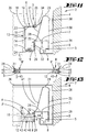
- Fig. 1
- einen Querschnitt durch die Schrankschublade mit angedeuteter Schrankwand,
- Fig. 2
- die Draufsicht auf den Einhängerahmen in Einzeldarstellung, besetzt mit in strichpunktierter Linienart wiedergegebenen Abfallbehältern,
- Fig. 3
- den Schnitt gemäß Linie III-III in Fig. 2,
- Fig. 4
- den Schnitt gemäß Linie IV-IV in Fig. 2,
- Fig. 5
- eine Draufsicht auf eine abgewandelte Ausführungsform des Einhängerahmens, aufweisend eine Zwischenstrebe,
- Fig. 6
- die Stirnansicht links,
- Fig. 7
- den Schnitt VII-VII in Fig. 5,
- Fig. 8
- in perspektivischer Darstellung den Küchenschrank mit Schrankschublade, partiell vorgezogen,
- Fig. 9
- den Küchenschrank in gleicher Darstellungsart bei maximal vorgezogener Schrankschublade, zeigend die eingehängten Abfallbehälter, erlaubend ihr bequemes Ausheben,
- Fig. 10
- eine Rückansicht des Küchenschrankes mit Sicht auf die Rückseite der Schrankschublade, veranschaulichend die hintere Stirnplatte,
- Fig. 11
- einen Querschnitt durch die Schrankschublade mit angedeuteter Schrankwand in bezüglich der Teleskopschienen abgewandelter Form,
- Fig. 12
- einen Querschnitt durch den hier tiefer gelegten
Einhängerahmen (R) der Schrankschublade,
zeigend eine gegenüber der
Grundversion Figur 1 abgewandelte Verstelleinrichtung, - Fig. 13
- eine vollständige rechtsseitige Schnittdarstellung der Schrankschublade.
- Fig. 1
- a cross section through the cabinet drawer with indicated cabinet wall,
- Fig. 2
- the top view of the hanging frame in individual representation, filled with waste containers shown in dash-dotted lines,
- Fig. 3
- the section along line III-III in Fig. 2,
- Fig. 4
- the section along line IV-IV in Fig. 2,
- Fig. 5
- 2 shows a plan view of a modified embodiment of the hanging frame, having an intermediate strut,
- Fig. 6
- the front view on the left,
- Fig. 7
- the section VII-VII in Fig. 5,
- Fig. 8
- in perspective the kitchen cupboard with cupboard drawer, partially pulled forward,
- Fig. 9
- the kitchen cupboard in the same display type with the cupboard drawer pulled out as far as possible, showing the suspended waste containers, allowing them to be conveniently lifted out,
- Fig. 10
- a rear view of the kitchen cabinet with a view of the rear of the cabinet drawer, illustrating the rear end plate,
- Fig. 11
- 3 shows a cross section through the cabinet drawer with the indicated cabinet wall in a form modified with respect to the telescopic rails,
- Fig. 12
- 3 shows a cross section through the hanging frame (R) of the cabinet drawer, which is lowered here, showing an adjusting device modified compared to the basic version in FIG. 1,
- Fig. 13
- a complete right-hand sectional view of the cabinet drawer.
Im Inneren 1 eines Küchenschrankes 2, insbesondere
Anbauschrankes einer Küchenzeile ist eine Schrankschublade
3 aufgenommen. Die ist horizontal schienengeführt
und lässt sich frontal in eine freie Vorstandslage
vorziehen.Inside 1 of a
Die Schienenführung ist durch an den Innenseiten seitlicher,
parallel verlaufender Schrankwände 4 gehalterte
Auszieh-Teleskopschienen 5 erreicht. Letztere bestehen
je aus einer feststehenden Schiene 6 und einer mitfahrenden
Schiene 7. Der Teleskopschiene 5 kann noch eine
Zwischenschiene (nicht dargestellt) zugeordnet sein,
wenn der erforderliche Ausfahrhub über eine zweigliedrige
Auszieh-Teleskopschiene 5 nicht ausreichend gegeben
ist.The rail guide is through on the inside,
4 wall units running in parallel
Extending
Die feststehende Schiene 6 sitzt fest an der Innenseite
der jeweiligen Schrankwand 4. Hierzu geht die besagte
Schiene 6 in eine Halterung 8 über. Bevorzugt handelt
es sich um eine flanschartige Leiste mit Befestigungsdurchbrechungen
für Schrauben oder dergleichen.The fixed
Im Gegenzug geht von der mitfahrenden Schiene 7 eine
zur Schrankschublade 3 führende Halterung aus. Die
besteht aus einem Längs-Befestigungswinkel 9. Beide
Längsseiten der Schrankschublade 3 sind so bestückt.In return, one of the traveling
Die beiden Längs-Befestigungswinkel 9 sind Teil einer
Rahmenkonstruktion. Rahmenergänzend bzw. -schließend
sind Stirnplatten 10 und 11, 10 eine vordere Stirnplatte
und 11 eine hintere Stirnplatte. Die vordere Stirnplatte
10 kann zugleich zu einer Blende gestaltet sein
mit Greifmöglichkeit für das bequeme Vorziehen der
Schrankschublade 3 und wieder Einschieben derselben.The two
Die rahmenschließenden Befestigungsmittel können klassischer Art sein, also Abwinkelungen mit Durchtrittslöchern für Befestigungsschrauben.The frame-closing fasteners can be more classic Be kind, i.e. bends with through holes for fastening screws.
Die horizontal ausgerichteten Längs-Befestigungswinkel
9 bilden den Träger eines bodenlosen Einhängerahmens R
der Schrankschublade 3. In diesem Einhängerahmen 3 ist
ein oder sind mehrere Abfallbehälter 12 freihängend
gehaltert. The horizontally aligned longitudinal mounting
Die Längs-Befestigungswinkel 9 nehmen gemäß dargestelltem
Ausführungsbeispiel den Einhängerahmen R mittelbar
auf. Zwischengeschaltet ist ein stabilisierendes Leistenprofil,
im Grunde praktisch ein U-Profil 13. Das
ist mit seiner U-Öffnung 14 rahmenauswärts gerichtet.
Sie weist gegen die Innenseite der korrespondierenden
Schrankwand 4.The
Der vertikale U-Steg 15 des U-Profils 13 setzt sich
oben in einen kürzeren U-Schenkel 16 und unten in einen
längeren U-Schenkel 17 fort, so dass in konkreter Verkörperung
gleichsam ein stehendes L-Profil vorliegt.The
Der obere, kürzere U-Schenkel 16 bildet das Auflager des Einhängerahmens R.The upper, shorter U-leg 16 forms the support of the hanging frame R.
Der Einhängerahmen R ist wie eine Aufsetzblende realisiert
und dem Auflager bezügl. deren U-Profile 13 steckzuordbar.
Er sitzt unter Steckspannung am U-Steg 15. Er
weist ferner ein L-Profil auf. Es ist liegend. Der
kürzere L-Profilschenkel weist abwärts gerichtet. Er
stellt die Rahmenöffnung 18, angepasst auf den Querschnitt
der Mantelwand des Abfallbehälters 12. Der
U-Steg 15 umschreibt, um das Maß der Dicke des abwärts
weisenden L-Profilschenkels des Einhängerahmen R verspringend,
gleichfalls die besagte Mantelwand. Die
nimmt nach unten gerichtet einen konischen Verlauf. Es
steht, wie Fig. 1 zeigt, auch ausreichendes Einhängespiel
zur Verfügung.The hanging frame R is implemented like a mounting panel
and the support. whose U-profiles 13 plug-in.
He sits under tension on the U-bridge 15. He
also has an L-profile. It is lying down. The
shorter L-profile legs point downwards. He
provides the
Die Hängeabstützung des Abfallbehälters 12 stellt dessen
nach auswärts und abwärts gewinkelter Randwulst als
Stützrand 19. The hanging support of the
Das Ergreifen des Abfallbehälters 12 geschieht in bekannter
Weise über abklappbare Tragbügel 20.The gripping of the
Weitere Details des Einhängerahmens R sind den Fig. 2 bis 7 entnehmbar. Die Kontur der in die Rahmenöffnung 18 einhängbaren Abfallbehälter ist in strichpunktierter Linienart in den Fig. 2 und 5 wiedergegeben.Further details of the hanging frame R are shown in FIG. 2 removable up to 7. The contour of the in the frame opening 18 attachable waste container is in dash-dotted lines Line type shown in Figs. 2 and 5.
In Fig. 2 ist eine Zwillingsbestückung realisiert. Dort
sind gleichgroße, im Wesentlichen rechteckigen Querschnitt
besitzende Abfallbehälter 12 in Längsrichtung
hintereinander liegend zugeordnet. Sie stützen einander
an der gemeinsamen Grenze ab. Es sei diesbezüglich auf
die Längsmitte verwiesen, wo aus Gründen der Deutlichkeit
ein etwas übertriebener Spalt 21 wiedergegeben
ist.A twin configuration is implemented in FIG. 2. There
are of equal size, essentially rectangular cross section
possessing
Gemäß Variante Fig. 5 liegt eine Veränderung des Grundrisses
insofern vor, als dort der Einhängerahmen R zwei
im Grunde rechteckige Rahmenöffnungen 18 hat, je zwillingsbestückt.
Eine Rahmenöffnung ist breitenmäßig etwa
auf die Hälfte der größeren Rahmenöffnung 18 gesetzt.
Die beiden Rahmenöffnungen 18 des Einhängerahmens R
sind über eine Zwischenstrebe 22 voneinander getrennt.
Auch in dieser Variante ist der Spalt 21 angegeben,
welcher auch hier so gering ist, dass es nicht zu einem
nennenswerten Verrutschen der eingehängten Abfallbehälter
12 kommen kann. Den Fig. 2 bis 7 ist überdies die
das beschriebene L-Profil begründende, rahmenversteifende
innere Abwinkelung entnehmbar, bezeichnet mit 23.
Solche Abwinkelungen 23 sind auch im Bereich der vorderen
Stirnplatte 10 und hinteren Stirnplatte 11 vorgenommen
bzw. realisierbar, gleichsam als willkommene Versteifung
fungierend und überdies auch anschlagmäßig
nutzbar. Die Abwinkelungen liegen hier außen bzw. auch
außen.According to variant Fig. 5 there is a change in the floor plan
insofar as there the hanging frame R two
basically has
Die Längs-Befestigungswinkel 9 der schubladenseitigen,
also mitfahrenden Schiene 7 erstrecken sich im Bereich
unterhalb der Schienen 6, 7. Der untere, längere U-Schenkel
17 des U-Profils 13 ruht auf dem horizontal abgewinkelten
Längs-Befestigungswinkel 9 und ist dort
gehaltert. Zur Befestigung dient beispielsweise ein
Niet 24. Der durchgreift die einander überlappenden
Enden der Teile 9, 17. Neben einem normalen Durchtrittsloch
an einem Teil kann der Längs-Befestigunswinkel 9
oder der untere U-Schenkel 17 ein Langloch 25 aufweisen.
Es sei auf Fig. 1 verwiesen. Dort ist erkennbar,
dass die besagten Langlöcher 25 sich in Richtung quer
zur Ausziehrichtung Pfeil x der Schrankschublade 3
erstrecken. So ergibt sich eine vorteilhafte und zugleich
einfache Verstelleinrichtung zur Bestimmung des
Spieles in dieser Richtung bezüglich der Rahmenöffnung
18. Für das senkrecht zu den Schrankwänden 4 gerichtete
Verstellen steht auch im Hinblick auf die Gestalt der
Längs-Befestigungswinkel 9 ein genügender Freiraum 26
zur Verfügung. Der liegt zwischen der Längsschmalkante
des unteren U-Schenkels 17 und einem davor vertikal
aufragenden Abschnitt 27 des Längs-Befestigungswinkels
9, der über eine auswärts gerichtete Abwinkelung in
einen Basisabschnitt 28 der mitfahrenden Schiene 7
übergeht.The
Die Auszieh-Teleskopschienen 5 sind, bezogen auf den
üblichen Betrachtungswinkel, der Sicht entzogen. Hierzu
dient eine oberseitige Abdeckung 29. Es handelt sich,
im Querschnitt gesehen, praktisch um U-Blech, leicht
einem V-Profil angenähert. Das ist oben in seinem U-Scheitel
gefällig gerundet und bildet mit einem abwärts
gerichteten rahmenöffnungs-fernen U-Schenkel eine Art
Abdeckschirm 30. Der andere, der Rahmenöffnung 18 näher
liegende U-Schenkel 31 ist in dieser Richtung rahmeneinwärts
schräg abfallend ausgebildet. Er geht in eine
konkave Rundung über und endet in einer markant nasenartigen
Ausformung 32, fungierend normalerweise als Niederhalter,
bzw. ergänzend eine Haltenut für den dem
Längs-Befestigungswinkel 9 wahlweise wieder zuzuordnenden
Boden der Schrankschublade 3. Dieser von einem
Brett oder dergleichen gebildete Boden trägt das Bezugszeichen
33 und ist in strichpunktierter Linienart in
Fig. 1 angedeutet.The extendable
Der sich im Anschluss an die horizontale Unterkante der
nasenartigen Ausformung 32 vertikal anschließende Endlappen
steht in Verbindung mit dem oben erläuterten
Abschnitt 27 des Längs-Befestigungswinkels 9. Die Verbindung
lässt sich wirtschaftlich durch Punktschweißung
erzielen.The following the horizontal lower edge of the
nose-
Der gegen die U-Öffnung 14 gehende Schenkel 31 ist
sodann noch in dem Sinne genutzt, als er zu einer Art
Fugendichtung herangezogen ist zwischen dem Körper der
Abdeckung 29 und dem Einhängerahmen R. Hier ist ein
Dichtprofil 34 zugeordnet. Zur Halterung des aus Gummi
oder dergleichen bestehenden Dichtprofils 34 dient der
Einhängerahmen R, konkret der nicht abgewinkelte Längsrand
desselben, so dass dieser als Träger des mit einem
entsprechenden Steckschuh 35 ausgestatteten Dichtprofils
34 nutzbar ist. Die Stirnkante des oberen Schenkels
des Steckschuhes 35 ist an der Längsschmalkante gefast,
so dass eine dichtende Auslippung besteht. Im
Rücken setzt sich der Schuh 35 als von oben gesehen
konkav gewölbter, aufragender Lappen fort, der, durch
leichtes Vorspannen federnd und somit gut dichtend, an
der korrespondierenden Breitfläche des Schenkels 31
anliegt. Die entsprechende Auskehlung vermeidet das
Entstehen von Schmutznestern. Es lässt sich vielmehr
eine bequeme Reinigung herbeiführen.The
Die oberseitige Öffnung der Schrankschublade 3 und
damit die der Abfallbehälter 12 ist deckelüberfangen.
Der entsprechende Deckel trägt das Bezugzeichen 36. Die
Unterseite seiner Decke 37 belässt ein gewisses Kluftmaß
zum Kamm der Abdeckung 29 und den oberseitig im
Wesentlichen höhengleich abschließenden Stirnplatten 10
und 11. So kann die Schrankschublade 3 störungsfrei die
Decke 37 unterlaufen. Wirkend als Geruchsverschluss,
kann eine Dichtleiste zwischengeschaltet sein.The top opening of the
Der Deckel 36 findet schrankbefestigungswandseitig eine
Abstützung. Erreicht ist die unter Mitwirkung seiner
Querschnittsgestalt. Die ist U-förmig. Der U-Steg
stellt die erwähnte Decke 37, wo hingegen die abwärts
gerichtet abgewinkelten U-Schenkel gleichsam als Wangen
38 auf der schrankwandseitigen Abstützung stehen, gebildet
durch die oben erläuterte Halterung 8 der feststehenden
Schiene 6. Der Deckel 36 ist lose auf diese
eingelegt.The
Erkennbar decken die Wangen 38 zusammen mit der in die
Horizontale übergehenden Randpartie der Decke 37 sowohl
die Abdeckung 29 als auch die schrankwandseitige Schiene
6 ab. Der diesbezügliche Einsteckschacht trägt das
Bezugszeichen 39.Visibly cover the
Beim Ziehen der Schrankschublade wird der tunnelartige
Deckel 36 selbst im Inneren 1 des Küchenschrankes 2
festgehalten. Hierzu können ortsfeste, rückhaltende
Elemente eingesetzt sein. Dabei ist es so, dass der
Deckel 36 mittels geeigneter Ausformungen 40 die Stirnflächen
der Halterung 8 der feststehenden Schiene 6
übergreift.When the cabinet drawer is pulled, it becomes tunnel-
Alternativ kann der aufsitzende Stirnrand der Wangen 38
gestuft sein und mit einer adäquaten Abstufung der
Halterung zusammenwirken, wobei die Stufe dann den
Auszug des Deckels 36 sperrt. Zum Entfernen des Deckels
36 muss dieser daher willensbetont ausgehoben werden,
um die Stufe oder die gleichwirkende Ausformung 40 zu
überwinden.Alternatively, the seated front edge of the
Gemäß Grundversion (vergleiche beispielsweise Figur 1)
sind feststehende Schiene 6 und mitfahrende Schiene 7
der Teleskopschienen 5 gegenüber den Längs-Befestigungswinkeln
9 deutlich nach oben versetzt angeordnet. Das
ist gemäß Weiterbildungen Figur 11 bis 13 geändert.
Erkennbar liegen die besagten Schienen 6, 7 ebenenmäßig
den Längs-Befestigungswinkeln 9 näher. Die Längs-Befestigungsschenkel
9 erstrecken sich praktisch auf Höhe
der Schienen 6,7 beziehungsweise umgekehrt.According to the basic version (compare for example Figure 1)
are fixed
Während der Einhängerahmen R gemäß Grundversion auf
Höhe der in einer höheren Ebene angeordneten Schienen
6, 7 angeordnet ist, liegt der Einhängerahmen R gemäß
Weiterbildung Figur 12 und 13 auf Höhe der in einer
tieferen Ebene liegenden Schienen 6, 7.While the hanging frame R according to the basic version
Height of the rails arranged at a
Die feststehende Schiene 6 ist gemäß Weiterbildungen
Figuren 11 bis 13 ebenfalls direkt an der Schrankwand 4
befestigt. Das geht über die nunmehr aufwärts abgewinkelte
Halterung 8, die mit dem oberen Stirnende ihres
vertikalen Abschnitts den aufsitzenden Stirnrand der
Wangen 38 des Deckels 36 trägt. The fixed
Sodann ist die im Querschnitt im Wesentlichen U-förmige
Abdeckung 29 weitergebildet. Sie ist zum vom Längs-Befestigungswinkel
9 ausgehenden, nach oben gehend U-förmig
gestalteten Basisabschnitt 28 und somit zur mitfahrenden
Schiene 7 hin geschlossen. Der mit 30 bezeichnete
Abdeckschirm steht nicht mehr gemäß Grundversion freiendend
im Einsteckschacht 39. Vielmehr geht der einen der
Schrankwand 4 näher liegenden Schenkel bildende Abdeckschirm
30 in den abgewinkelten Schenkel des Basisabschnitts
28 über. Er ist daran befestigt, beispielsweise
durch Punktschweißung gehaltert. So ergibt sich für
den konsolenbildenden Abschnitt des Längs-Befestigungswinkels
9 eine stabile, die Basis 28 überlagernde Kastenprofilierung.Then the cross-section is essentially
Die entsprechend kastenprofilierend mitwirkende Beiziehung
des schrägen Schenkels 31 der Abdeckung 29 ist im
Rahmen der Grundversion erläutert. Die Bezugsziffern
sind sinngemäß angewandt. Der Niet 24 stellt das Verbindungsglied
zum U-Profil 13, welches den gemäß Grundversion
und gemäß Figur 11 oben angeordneten Einhängerahmen
R trägt.The corresponding involvement in box profiling
of the
Gemäß Grundversion und Figur 11 endet der schräg abfallende,
spitzwinkelig in Richtung der Steilwand des
Abfallbehälters 12 verlaufende schräge Schenkel 31
unterhalb des oben liegenden Einhängerahmens R. Wie der
Zeichnung entnehmbar ist, weist das spitznasenartig
geformte Ende des Schenkels 31 in die U-Öffnung 14 des
U-Profiles 13.According to the basic version and FIG. 11, the sloping,
acute angle in the direction of the steep face of the
In der Variante Figuren 12 und 13 ist das U-Profil 13
einschließlich des Dichtungsprofiles 14 zur Abdeckung
29 hin nicht mehr verwendet. Dort ist der tiefliegende
Längs-Befestigungswinkel 9, und zwar sein horizontaler
Schenkel, als Auflager für den tiefer gelegten Einhängerahmen
R herangezogen. Der nun ganz frei liegende,
innenseitige Schenkel 31 der kastenprofilartig zur
mitfahrenden Schiene hin 7 geschlossenen Abdeckung 29
stellt nunmehr zumindest in Verfahrrichtung der Schrankschublade
3 verlaufend einen der Öffnung des Abfallbehälters
12 vorgelagerten Einwurftrichter 41.In the variant FIGS. 12 and 13, the U-profile is 13
including the sealing
Die Figuren 12 und 13 geben eine Verstelleinrichtung
an, über die sich die Rahmenöffnung 18 zumindest quer
zur Verlagerungsrichtung der Schrankschublade 3 verändern
lässt und zwar im Sinne eines ausreichenden Untergriffs
des Stützrandes 19 des Abfallbehälters 12. Das
verkörpert sich baulich darin, dass der Einhängerahmen
R, jedenfalls an seinen Längsschenkeln, ein zur Zusammenwirkung
mit dem Längs-Befestigungswinkel 9 dienendes
Verstellteil 42 aufweist. Das ruht auf dem horizontalen
Schenkel des Längs-Befestigungswinkels 9. Es reicht
höhenmäßig bis zur Unterseite der ausspitzenden Nase
des innenseitigen Schenkels 31. Die Nase überragt erkennbar
den vertikalen Abschnitt 27, an dessen Rückseite,
auch hier die Ausformung 32 bietend, in den Basisabschnitt
28, stellend die mitfahrende Schiene 7, übergeht.
Das Verstellteil 42 ist im Grunde zweiteilig. Es
besitzt ein Festteil a und ein Bewegeteil b.Figures 12 and 13 provide an adjustment device
over which the
Das Verstellteil 42 nimmt einen Horizontalschenkel 43
eines Einhängeprofiles R' verstellbar auf. Der Horizontalschenkel
43 steckt in einer entsprechend ausgerichteten,
passenden, behälterseitig offenen Nut 44 des Festteiles
a.The
Das Verstellteil 42 ist sowohl bezüglich des Festteiles
a als auch des Bewegeteils b leistenförmig. Es kann
sich baustoffmäßig um Holz, Metall oder Kunststoffleisten
handeln.The
Das Festteil a ist im Grunde U-profiliert, wobei die
U-Öffnung die besagte Nut 44 stellt. Der dem Längs-Befestigungswinkel
9 näher liegende Schenkel des U-Profiles
ist wandungsdicker. Der obere, im Bereich des U-Steges
durch die ausspitzende Nase überfangene Schenkel ist
stirnseitig abgeschrägt, so dass sich ein in Richtung
des davor aufliegenden Stützrandes 19 abfallender Hang
bildet. Der bildet zusammen mit dem in Gegenrichtung
abgeschrägten Stirnrand des Stützrandes 19 eine V-Kerbe.The fixed part a is basically U-shaped, the
U-opening said
Das Einhängeprofil R', gebildet durch das Bewegeteil b,
ist, im Querschnitt gesehen, winkelförmig, genauer
L-förmig. Der längere L-Schenkel stellt den Horizontalschenkel
43. Der kürzere L-Schenkel schließt mit der
Unterseite des aufliegenden Festteils a bündig ab.The hanging profile R ', formed by the moving part b,
seen in cross section, is angular, more precise
L-shaped. The longer L-leg represents the
Figur 12 zeigt das Einrichten des dortigen Einhängerahmens
R beziehungsweise der längsseitigen Einhängeprofile
R'. Linksseitig ist die maximale Öffnungsweite des
Einhängerahmens R eingestellt, rechtsseitig eine Zwischenstellung
herbeigeführt. Die Verstelleinrichtungen
sind lediglich noch zu fixieren. Das geschieht über ein
Befestigungselement 45. Es kann sich um eine Schraube
handeln. Die geht von der Unterseite des horizontalen
Schenkels des Längs-Befestigungswinkels 9 aus, welcher
eine Bohrung aufweist, durch welche der oben erläuterte
Niet 24 eingezogen wurde.Figure 12 shows the installation of the hanging frame there
R or the longitudinal suspension profiles
R '. On the left is the maximum opening width of the
Hanging frame R set, an intermediate position on the right
brought about. The adjustment devices
only have to be fixed. That happens through a
Die praktisch deckungsgleich zur Bohrung liegende Befestigungsausnehmung
für das Befestigungselement 45 trägt
das Bezugszeichen 46. Es handelt sich um eine die horizontale
Nut 44 querende Sackbohrung, die auf mittlerer
Dicke des oberen Schenkels des Festteiles a endet. Mit
Einziehen des Befestigungselements 45 ist die Lage
positioniert. Der horizontale Schenkel 43 des Bewegeteiles
b respektive Einhängeprofils R 1 ist selbstredend
durchdringbar, dies praktisch in Wirkung einer
durch selbstschneidendes Gewinde erzielten Mutter.The fastening recess, which is practically congruent with the hole
for the
Die Längs-Befestigungswinkel 9 können konsolestellend
auch innenseitig der Stirnplatten 10, 11 angebracht
sein, wobei dann einfach der vertikale Schenkel des
Winkels als frontal beispielsweise mit der Blende
sprich vorderen Stirnplatte 10 verbindbarer Flansch
genutzt wird. Die Befestigung an der hinteren Stirnplatte
11 ist entsprechend auszuführen. Dazwischen stützt
sich der Einhängerahmen R peripher ab.The
Alle offenbarten Merkmale sind (für sich) erfindungswesentlich. In die Offenbarung der Anmeldung wird hiermit auch der Offenbarungsinhalt der zugehörigen/beigefügten Prioritätsunterlagen (Abschrift der Voranmeldung) vollinhaltlich mit einbezogen, auch zu dem Zweck, Merkmale dieser Unterlagen in Ansprüche vorliegender Anmeldung mit aufzunehmen.All of the features disclosed are (in themselves) essential to the invention. In the disclosure of the registration is hereby also the disclosure content of the associated / attached Priority documents (copy of the pre-registration) in full included, also for the purpose of features of these documents in claims of the present application to include.
Claims (23)
Priority Applications (1)
| Application Number | Priority Date | Filing Date | Title |
|---|---|---|---|
| DE20122381U DE20122381U1 (en) | 2000-03-23 | 2001-03-21 | Drawer, especially kitchen cupboard drawer, has longitudinal fastening angle pieces fitted to it and in form of bottom-less rigid suspension frame of L-shaped cross section in which freely hang one or more waste containers |
Applications Claiming Priority (6)
| Application Number | Priority Date | Filing Date | Title |
|---|---|---|---|
| DE10014520 | 2000-03-23 | ||
| DE10014520 | 2000-03-23 | ||
| DE10035478 | 2000-07-21 | ||
| DE10035478 | 2000-07-21 | ||
| DE10111329 | 2001-03-08 | ||
| DE10111329A DE10111329A1 (en) | 2000-03-23 | 2001-03-08 | Drawer accommodated in a cupboard, in particular kitchen cupboard drawer |
Publications (3)
| Publication Number | Publication Date |
|---|---|
| EP1136392A2 true EP1136392A2 (en) | 2001-09-26 |
| EP1136392A3 EP1136392A3 (en) | 2003-09-24 |
| EP1136392B1 EP1136392B1 (en) | 2008-07-16 |
Family
ID=27213750
Family Applications (1)
| Application Number | Title | Priority Date | Filing Date |
|---|---|---|---|
| EP01107057A Expired - Lifetime EP1136392B1 (en) | 2000-03-23 | 2001-03-21 | Drawer for a cabinet, in particular a kitchen cabinet, for supporting waste receptacles |
Country Status (2)
| Country | Link |
|---|---|
| US (1) | US20020024276A1 (en) |
| EP (1) | EP1136392B1 (en) |
Cited By (15)
| Publication number | Priority date | Publication date | Assignee | Title |
|---|---|---|---|---|
| EP1716783A2 (en) | 2005-04-29 | 2006-11-02 | Westermann KG | Drawer for a cabinet |
| EP1792851A1 (en) * | 2005-11-30 | 2007-06-06 | Westermann KG | Refuse receptacle withdrawal device |
| EP1946673A1 (en) * | 2007-01-22 | 2008-07-23 | Peka-Metall Ag | Extraction device for holding a container system for use in a cupboard element in a furniture unit |
| EP2340743A1 (en) * | 2010-01-05 | 2011-07-06 | Hailo-Werk Rudolf Loh GmbH & Co. KG | Drawer for a kitchen cabinet |
| WO2011094789A1 (en) * | 2010-02-05 | 2011-08-11 | Julius Blum Gmbh | Furniture pull-out |
| DE202012011677U1 (en) | 2012-12-06 | 2013-01-16 | Wälde GmbH | Mobile holder for waste containers |
| WO2013111123A1 (en) * | 2012-01-27 | 2013-08-01 | Romagna Plastic S.R.L. | Drawer for separate waste collection |
| EP2649904A1 (en) * | 2012-04-11 | 2013-10-16 | Westermann KG | Bracket for holding a lid and a pull-out waste collector in a cabinet |
| EP2649905A1 (en) * | 2012-04-11 | 2013-10-16 | Westermann KG | Frame covering plinth and drawer |
| EP2803601A1 (en) * | 2013-05-10 | 2014-11-19 | Westermann KG | Pull-out waste collector |
| DE202014102726U1 (en) * | 2014-06-12 | 2015-09-15 | Ninkaplast Gmbh | Suspension frame for waste containers in furniture pull-outs |
| DE202017102855U1 (en) | 2017-05-12 | 2018-08-23 | Westermann Kg | Drawer, preferably without floor and for a kitchen cupboard |
| DE202019106909U1 (en) * | 2019-12-11 | 2021-03-15 | Westermann Kg | Drawer, in particular kitchen cabinet drawer |
| EP3834663A1 (en) | 2019-12-11 | 2021-06-16 | Westermann KG | Drawer, in particular a kitchen cabinet drawer |
| US11691811B2 (en) | 2017-10-13 | 2023-07-04 | Bluewater Rise Investments Limited | Container apparatus and a container mounting collar |
Families Citing this family (12)
| Publication number | Priority date | Publication date | Assignee | Title |
|---|---|---|---|---|
| NZ530285A (en) * | 2003-12-19 | 2005-11-25 | Peter Stanford Johnson | Bin |
| DE202011050248U1 (en) | 2011-05-24 | 2012-08-27 | Westermann Kg | cupboard drawer |
| DE202011052321U1 (en) | 2011-10-19 | 2013-01-23 | Westermann Kg | guide frame |
| DE202013012106U1 (en) | 2013-05-10 | 2015-04-01 | Vauth-Sagel Holding Gmbh & Co. Kg | Furniture fitting for forming an extendable waste collection device |
| DE202015102244U1 (en) | 2015-03-20 | 2016-06-22 | Westermann Kg | Kitchen cabinet with a sink, installation arrangement for a kitchen cupboard and cabinet drawer |
| DK3072415T3 (en) | 2015-03-25 | 2018-06-14 | Vauth Sagel Holding Gmbh & Co Kg | Furniture fittings for designing a retractable waste collection device and cabinet with such furniture fittings |
| ITBO20150032U1 (en) * | 2015-04-22 | 2016-10-22 | Giacomo Gollinucci | DRAWER AND HOUSING, IN PARTICULAR FOR THE DIFFERENTIATED COLLECTION OF WASTE |
| CA2972046A1 (en) * | 2016-06-30 | 2017-12-30 | Giacomo Gollinucci | Bin holder carcass and drawer, in particular for separate waste collection |
| AR111124A1 (en) | 2017-03-13 | 2019-06-05 | Dow Global Technologies Llc | METHODS FOR MANUFACTURING LIGHT OLEFINS FROM DIFFERENT POWER SUPPLY CURRENTS |
| AR111237A1 (en) | 2017-03-13 | 2019-06-19 | Dow Global Technologies Llc | METHODS AND APPLIANCES TO FORM LIGHT OLEFINS BY CRAQUEO |
| IT202000017080A1 (en) * | 2020-07-14 | 2022-01-14 | Sige S P A | CONTAINER HOLDER DEVICE. |
| DE202021106277U1 (en) * | 2021-11-17 | 2023-02-20 | Westermann Kg | Drawer, in particular kitchen cupboard drawer |
Citations (4)
| Publication number | Priority date | Publication date | Assignee | Title |
|---|---|---|---|---|
| WO1992007494A1 (en) * | 1990-10-29 | 1992-05-14 | Sari Scheinberg Med Yes You Can | Inset element for cupboards |
| US5251975A (en) * | 1992-03-13 | 1993-10-12 | Braun Thomas F | Extendable and retractable undercounter container assembly for recyclable materials |
| DE9414004U1 (en) * | 1993-10-11 | 1995-02-16 | Hailo-Werk Rudolf Loh GmbH & Co KG, 35708 Haiger | Carrier for waste collectors |
| DE19805186C1 (en) * | 1998-02-10 | 1999-02-11 | Blanco Gmbh & Co Kg | Cupboard furniture integral waste collector |
-
2001
- 2001-03-20 US US09/812,800 patent/US20020024276A1/en not_active Abandoned
- 2001-03-21 EP EP01107057A patent/EP1136392B1/en not_active Expired - Lifetime
Patent Citations (4)
| Publication number | Priority date | Publication date | Assignee | Title |
|---|---|---|---|---|
| WO1992007494A1 (en) * | 1990-10-29 | 1992-05-14 | Sari Scheinberg Med Yes You Can | Inset element for cupboards |
| US5251975A (en) * | 1992-03-13 | 1993-10-12 | Braun Thomas F | Extendable and retractable undercounter container assembly for recyclable materials |
| DE9414004U1 (en) * | 1993-10-11 | 1995-02-16 | Hailo-Werk Rudolf Loh GmbH & Co KG, 35708 Haiger | Carrier for waste collectors |
| DE19805186C1 (en) * | 1998-02-10 | 1999-02-11 | Blanco Gmbh & Co Kg | Cupboard furniture integral waste collector |
Cited By (17)
| Publication number | Priority date | Publication date | Assignee | Title |
|---|---|---|---|---|
| EP1716783A2 (en) | 2005-04-29 | 2006-11-02 | Westermann KG | Drawer for a cabinet |
| EP1792851A1 (en) * | 2005-11-30 | 2007-06-06 | Westermann KG | Refuse receptacle withdrawal device |
| EP1946673A1 (en) * | 2007-01-22 | 2008-07-23 | Peka-Metall Ag | Extraction device for holding a container system for use in a cupboard element in a furniture unit |
| EP2340743A1 (en) * | 2010-01-05 | 2011-07-06 | Hailo-Werk Rudolf Loh GmbH & Co. KG | Drawer for a kitchen cabinet |
| US8622493B2 (en) | 2010-02-05 | 2014-01-07 | Julius Blum Gmbh | Furniture pull-out |
| WO2011094789A1 (en) * | 2010-02-05 | 2011-08-11 | Julius Blum Gmbh | Furniture pull-out |
| AU2013213278B2 (en) * | 2012-01-27 | 2017-06-15 | Romagna Plastic S.R.L. | Drawer for separate waste collection |
| WO2013111123A1 (en) * | 2012-01-27 | 2013-08-01 | Romagna Plastic S.R.L. | Drawer for separate waste collection |
| EP2649904A1 (en) * | 2012-04-11 | 2013-10-16 | Westermann KG | Bracket for holding a lid and a pull-out waste collector in a cabinet |
| EP2649905A1 (en) * | 2012-04-11 | 2013-10-16 | Westermann KG | Frame covering plinth and drawer |
| DE202012011677U1 (en) | 2012-12-06 | 2013-01-16 | Wälde GmbH | Mobile holder for waste containers |
| EP2803601A1 (en) * | 2013-05-10 | 2014-11-19 | Westermann KG | Pull-out waste collector |
| DE202014102726U1 (en) * | 2014-06-12 | 2015-09-15 | Ninkaplast Gmbh | Suspension frame for waste containers in furniture pull-outs |
| DE202017102855U1 (en) | 2017-05-12 | 2018-08-23 | Westermann Kg | Drawer, preferably without floor and for a kitchen cupboard |
| US11691811B2 (en) | 2017-10-13 | 2023-07-04 | Bluewater Rise Investments Limited | Container apparatus and a container mounting collar |
| DE202019106909U1 (en) * | 2019-12-11 | 2021-03-15 | Westermann Kg | Drawer, in particular kitchen cabinet drawer |
| EP3834663A1 (en) | 2019-12-11 | 2021-06-16 | Westermann KG | Drawer, in particular a kitchen cabinet drawer |
Also Published As
| Publication number | Publication date |
|---|---|
| EP1136392A3 (en) | 2003-09-24 |
| EP1136392B1 (en) | 2008-07-16 |
| US20020024276A1 (en) | 2002-02-28 |
Similar Documents
| Publication | Publication Date | Title |
|---|---|---|
| EP1136392A2 (en) | Drawer for a cabinet, in particular a kitchen cabinet, for supporting waste receptacles | |
| DE102007005952A1 (en) | Refrigerating appliance with shelves suspended from a rail | |
| DE8816223U1 (en) | Drawer, hanging frame or similar. | |
| DE2264198C3 (en) | Awning box attachment | |
| DE3024972C2 (en) | Pull-out, especially pot pull-out, for furniture | |
| DE3703544C1 (en) | Waste container with coupling agent | |
| DE202020107106U1 (en) | Drawer, in particular kitchen cabinet drawer | |
| DE202006011412U1 (en) | Presentation arrangement for a shelf shelf | |
| DE19842666B4 (en) | In a cabinet with a cabinet bottom built-in, extendable by rails Ausfahrbehältnisse | |
| DE19622137C2 (en) | Cladding for mobile rubbish bins | |
| DE20122381U1 (en) | Drawer, especially kitchen cupboard drawer, has longitudinal fastening angle pieces fitted to it and in form of bottom-less rigid suspension frame of L-shaped cross section in which freely hang one or more waste containers | |
| DE3120263C2 (en) | Front pull-out for a tall cabinet, especially a tall kitchen cabinet | |
| DE10111329A1 (en) | Drawer accommodated in a cupboard, in particular kitchen cupboard drawer | |
| DE3720817C2 (en) | Coupling device for tipping waste containers out of a cabinet | |
| EP0388655A2 (en) | Metallic drawer | |
| WO2002002438A1 (en) | Waste receiving device | |
| DE102016118381A1 (en) | Retaining frame accommodated in extension rails | |
| DE8017727U1 (en) | EXTRACT, IN PARTICULAR POT EXTRACT | |
| DE8905348U1 (en) | Metal drawer side frame | |
| DE3913953C2 (en) | ||
| DE3011458A1 (en) | DEVICE FOR SEALING A DOOR GAP | |
| DE19612321C1 (en) | Rubbish container with lever bars on two opposing sides | |
| EP4432881A1 (en) | Drawer, in particular kitchen cupboard drawer | |
| EP0781716A1 (en) | Cover for a refuse container | |
| DE8905311U1 (en) | Drawer side frame with wall plate |
Legal Events
| Date | Code | Title | Description |
|---|---|---|---|
| PUAI | Public reference made under article 153(3) epc to a published international application that has entered the european phase |
Free format text: ORIGINAL CODE: 0009012 |
|
| AK | Designated contracting states |
Kind code of ref document: A2 Designated state(s): AT BE CH CY DE DK ES FI FR GB GR IE IT LI LU MC NL PT SE TR |
|
| AX | Request for extension of the european patent |
Free format text: AL;LT;LV;MK;RO;SI |
|
| RIC1 | Information provided on ipc code assigned before grant |
Ipc: 7B 65F 1/14 A Ipc: 7A 47B 77/18 B |
|
| PUAL | Search report despatched |
Free format text: ORIGINAL CODE: 0009013 |
|
| AK | Designated contracting states |
Kind code of ref document: A3 Designated state(s): AT BE CH CY DE DK ES FI FR GB GR IE IT LI LU MC NL PT SE TR |
|
| AX | Request for extension of the european patent |
Extension state: AL LT LV MK RO SI |
|
| 17P | Request for examination filed |
Effective date: 20040204 |
|
| AKX | Designation fees paid |
Designated state(s): AT BE CH CY DE DK ES FI FR GB GR IE IT LI LU MC NL PT SE TR |
|
| 17Q | First examination report despatched |
Effective date: 20070403 |
|
| GRAP | Despatch of communication of intention to grant a patent |
Free format text: ORIGINAL CODE: EPIDOSNIGR1 |
|
| GRAS | Grant fee paid |
Free format text: ORIGINAL CODE: EPIDOSNIGR3 |
|
| GRAA | (expected) grant |
Free format text: ORIGINAL CODE: 0009210 |
|
| AK | Designated contracting states |
Kind code of ref document: B1 Designated state(s): AT BE CH CY DE DK ES FI FR GB GR IE IT LI LU MC NL PT SE TR |
|
| REG | Reference to a national code |
Ref country code: GB Ref legal event code: FG4D Free format text: NOT ENGLISH |
|
| REG | Reference to a national code |
Ref country code: CH Ref legal event code: EP |
|
| REF | Corresponds to: |
Ref document number: 50114104 Country of ref document: DE Date of ref document: 20080828 Kind code of ref document: P |
|
| REG | Reference to a national code |
Ref country code: IE Ref legal event code: FG4D Free format text: LANGUAGE OF EP DOCUMENT: GERMAN |
|
| REG | Reference to a national code |
Ref country code: CH Ref legal event code: NV Representative=s name: R. A. EGLI & CO. PATENTANWAELTE |
|
| PG25 | Lapsed in a contracting state [announced via postgrant information from national office to epo] |
Ref country code: ES Free format text: LAPSE BECAUSE OF FAILURE TO SUBMIT A TRANSLATION OF THE DESCRIPTION OR TO PAY THE FEE WITHIN THE PRESCRIBED TIME-LIMIT Effective date: 20081027 Ref country code: PT Free format text: LAPSE BECAUSE OF FAILURE TO SUBMIT A TRANSLATION OF THE DESCRIPTION OR TO PAY THE FEE WITHIN THE PRESCRIBED TIME-LIMIT Effective date: 20081216 |
|
| REG | Reference to a national code |
Ref country code: IE Ref legal event code: FD4D |
|
| PG25 | Lapsed in a contracting state [announced via postgrant information from national office to epo] |
Ref country code: DK Free format text: LAPSE BECAUSE OF FAILURE TO SUBMIT A TRANSLATION OF THE DESCRIPTION OR TO PAY THE FEE WITHIN THE PRESCRIBED TIME-LIMIT Effective date: 20080716 Ref country code: IE Free format text: LAPSE BECAUSE OF FAILURE TO SUBMIT A TRANSLATION OF THE DESCRIPTION OR TO PAY THE FEE WITHIN THE PRESCRIBED TIME-LIMIT Effective date: 20080716 |
|
| PLBE | No opposition filed within time limit |
Free format text: ORIGINAL CODE: 0009261 |
|
| STAA | Information on the status of an ep patent application or granted ep patent |
Free format text: STATUS: NO OPPOSITION FILED WITHIN TIME LIMIT |
|
| PGFP | Annual fee paid to national office [announced via postgrant information from national office to epo] |
Ref country code: FI Payment date: 20090313 Year of fee payment: 9 Ref country code: NL Payment date: 20090312 Year of fee payment: 9 |
|
| 26N | No opposition filed |
Effective date: 20090417 |
|
| PGFP | Annual fee paid to national office [announced via postgrant information from national office to epo] |
Ref country code: CH Payment date: 20090316 Year of fee payment: 9 |
|
| PGFP | Annual fee paid to national office [announced via postgrant information from national office to epo] |
Ref country code: IT Payment date: 20090326 Year of fee payment: 9 |
|
| BERE | Be: lapsed |
Owner name: WESTERMANN K.G. Effective date: 20090331 |
|
| PG25 | Lapsed in a contracting state [announced via postgrant information from national office to epo] |
Ref country code: MC Free format text: LAPSE BECAUSE OF NON-PAYMENT OF DUE FEES Effective date: 20090331 |
|
| REG | Reference to a national code |
Ref country code: FR Ref legal event code: ST Effective date: 20091130 |
|
| PG25 | Lapsed in a contracting state [announced via postgrant information from national office to epo] |
Ref country code: SE Free format text: LAPSE BECAUSE OF FAILURE TO SUBMIT A TRANSLATION OF THE DESCRIPTION OR TO PAY THE FEE WITHIN THE PRESCRIBED TIME-LIMIT Effective date: 20081016 |
|
| PG25 | Lapsed in a contracting state [announced via postgrant information from national office to epo] |
Ref country code: BE Free format text: LAPSE BECAUSE OF NON-PAYMENT OF DUE FEES Effective date: 20090331 |
|
| PG25 | Lapsed in a contracting state [announced via postgrant information from national office to epo] |
Ref country code: FR Free format text: LAPSE BECAUSE OF NON-PAYMENT OF DUE FEES Effective date: 20091123 |
|
| PGFP | Annual fee paid to national office [announced via postgrant information from national office to epo] |
Ref country code: AT Payment date: 20100305 Year of fee payment: 10 Ref country code: GB Payment date: 20100309 Year of fee payment: 10 |
|
| REG | Reference to a national code |
Ref country code: NL Ref legal event code: V1 Effective date: 20101001 |
|
| PG25 | Lapsed in a contracting state [announced via postgrant information from national office to epo] |
Ref country code: GR Free format text: LAPSE BECAUSE OF FAILURE TO SUBMIT A TRANSLATION OF THE DESCRIPTION OR TO PAY THE FEE WITHIN THE PRESCRIBED TIME-LIMIT Effective date: 20081017 |
|
| REG | Reference to a national code |
Ref country code: CH Ref legal event code: PL |
|
| PG25 | Lapsed in a contracting state [announced via postgrant information from national office to epo] |
Ref country code: FI Free format text: LAPSE BECAUSE OF NON-PAYMENT OF DUE FEES Effective date: 20100321 |
|
| PG25 | Lapsed in a contracting state [announced via postgrant information from national office to epo] |
Ref country code: NL Free format text: LAPSE BECAUSE OF NON-PAYMENT OF DUE FEES Effective date: 20101001 |
|
| PG25 | Lapsed in a contracting state [announced via postgrant information from national office to epo] |
Ref country code: LI Free format text: LAPSE BECAUSE OF NON-PAYMENT OF DUE FEES Effective date: 20100331 Ref country code: CH Free format text: LAPSE BECAUSE OF NON-PAYMENT OF DUE FEES Effective date: 20100331 |
|
| PG25 | Lapsed in a contracting state [announced via postgrant information from national office to epo] |
Ref country code: IT Free format text: LAPSE BECAUSE OF NON-PAYMENT OF DUE FEES Effective date: 20100321 |
|
| PG25 | Lapsed in a contracting state [announced via postgrant information from national office to epo] |
Ref country code: LU Free format text: LAPSE BECAUSE OF NON-PAYMENT OF DUE FEES Effective date: 20090321 |
|
| PG25 | Lapsed in a contracting state [announced via postgrant information from national office to epo] |
Ref country code: TR Free format text: LAPSE BECAUSE OF FAILURE TO SUBMIT A TRANSLATION OF THE DESCRIPTION OR TO PAY THE FEE WITHIN THE PRESCRIBED TIME-LIMIT Effective date: 20080716 |
|
| PG25 | Lapsed in a contracting state [announced via postgrant information from national office to epo] |
Ref country code: CY Free format text: LAPSE BECAUSE OF FAILURE TO SUBMIT A TRANSLATION OF THE DESCRIPTION OR TO PAY THE FEE WITHIN THE PRESCRIBED TIME-LIMIT Effective date: 20080716 |
|
| GBPC | Gb: european patent ceased through non-payment of renewal fee |
Effective date: 20110321 |
|
| PG25 | Lapsed in a contracting state [announced via postgrant information from national office to epo] |
Ref country code: AT Free format text: LAPSE BECAUSE OF NON-PAYMENT OF DUE FEES Effective date: 20110321 |
|
| PG25 | Lapsed in a contracting state [announced via postgrant information from national office to epo] |
Ref country code: GB Free format text: LAPSE BECAUSE OF NON-PAYMENT OF DUE FEES Effective date: 20110321 |
|
| PGFP | Annual fee paid to national office [announced via postgrant information from national office to epo] |
Ref country code: DE Payment date: 20200317 Year of fee payment: 20 |
|
| REG | Reference to a national code |
Ref country code: DE Ref legal event code: R071 Ref document number: 50114104 Country of ref document: DE |