EP1010809B1 - Clearing apparatus with a plastic blade - Google Patents
Clearing apparatus with a plastic blade Download PDFInfo
- Publication number
- EP1010809B1 EP1010809B1 EP99113621A EP99113621A EP1010809B1 EP 1010809 B1 EP1010809 B1 EP 1010809B1 EP 99113621 A EP99113621 A EP 99113621A EP 99113621 A EP99113621 A EP 99113621A EP 1010809 B1 EP1010809 B1 EP 1010809B1
- Authority
- EP
- European Patent Office
- Prior art keywords
- mouldboard
- gap
- clearing device
- frame
- clearing
- Prior art date
- Legal status (The legal status is an assumption and is not a legal conclusion. Google has not performed a legal analysis and makes no representation as to the accuracy of the status listed.)
- Expired - Lifetime
Links
Images






Classifications
-
- E—FIXED CONSTRUCTIONS
- E01—CONSTRUCTION OF ROADS, RAILWAYS, OR BRIDGES
- E01H—STREET CLEANING; CLEANING OF PERMANENT WAYS; CLEANING BEACHES; DISPERSING OR PREVENTING FOG IN GENERAL CLEANING STREET OR RAILWAY FURNITURE OR TUNNEL WALLS
- E01H5/00—Removing snow or ice from roads or like surfaces; Grading or roughening snow or ice
- E01H5/04—Apparatus propelled by animal or engine power; Apparatus propelled by hand with driven dislodging or conveying levelling elements, conveying pneumatically for the dislodged material
- E01H5/06—Apparatus propelled by animal or engine power; Apparatus propelled by hand with driven dislodging or conveying levelling elements, conveying pneumatically for the dislodged material dislodging essentially by non-driven elements, e.g. scraper blades, snow-plough blades, scoop blades
- E01H5/065—Apparatus propelled by animal or engine power; Apparatus propelled by hand with driven dislodging or conveying levelling elements, conveying pneumatically for the dislodged material dislodging essentially by non-driven elements, e.g. scraper blades, snow-plough blades, scoop blades characterised by the form of the snow-plough blade, e.g. flexible, or by snow-plough blade accessories
Definitions
- the invention relates generally to clearing devices and in particular an improvement of a clearing device and similar devices for clearing snow and other fillings, of roads, paths and similar surfaces.
- the invention is particularly applicable to snow plows, whereby an improved plow or clearing device is created.
- the invention is described below with reference to a snow removal device described.
- the invention can be used in others Broaches or plows, e.g. used in agriculture will find application.
- a plow as a snow clearing device for clearing or removing of snow from streets has a shovel that Snow rolls up and then across the front of the Shovel moves.
- the clearing device a scraper with a curved structure on the bottom in a lower clearing edge or a scraper blade ends.
- the Scraper blade usually extends in the direction of travel forward to dig into the snow and the snow to squeeze into the curved scraper.
- the contour of the Clearing boards conduct a twist in the upward moving Snow and forcing the snow over the front of the clearing board across to the side of the clearing device.
- a typical snow plow construction is one Low carbon steel plate, usually with a thickness of about 3.2 mm (1/8 ") into an arc shape to make the Training clearing board.
- the frame construction the usual is constructed from angle profile components, is then welded to the back of the clearing board to support it and to prevent the scraper from breaking or kinking when it does hits stones or other piles on the street, whereby the frame construction also for fastening the for operation necessary components of the clearing device. Examples of such Constructions can be found in patents US 3,432,947 and US 3,465,456, which have been assigned to the applicant.
- a clearing board is made of steel not desirable.
- a steel clearing board requires higher loads the vehicle to which it is attached, and in particular it requires a stronger broach attachment and larger ones Lifting systems than would otherwise be possible.
- the snow plows have been significantly improved as a polyethylene material with a high molecular weight used as a clearing board has been designed to be durable, lightweight and to create significantly improved snow clearing plows as he does in the patents US 4,803,790 and US 4,845,866.
- This in U.S. Patent 4,803,790 clearing device has a conventional one Frame on, the upper and lower longitudinally extending Mounting elements with approximately the same length as that Plow shovel and a variety of vertically extending, has transversely spaced transverse struts. Every cross strut is included one end to the top mounting member and the other End attached to the lower mounting element and has one concave (inward) curved front face, the extends between the upper and lower mounting members.
- An essentially rectangular and concave curve High molecular weight polyethylene scraper is by means of screw fasteners on the upper and lower Mounting element in a curved or prestressed manner attached.
- the back of the attached clearing board has from the front end faces of the cross struts pointing in the direction of travel a fixed distance, so that between the dozer board and cross strut a space remains free. This distance or space one contact is sufficient in normal operation of the clearing device between the dozer board or dozer blade and the cross struts to prevent during extreme impact impacts from fillings contact with the struts becomes possible.
- the clearing board bends springily into the space or out when heavy or wet snow needs to be cleared, and this Bending improves the lateral movement and rolling movement of the Snow over the front surface of the snowboard. So far they worry Frame / clearing board mounting arrangements for a transverse support of the Clearing boards to prevent breakage of the clearing board when the clearing board is impacted by heavy fillings. Therefore, this construction has for a significant improvement of the state of the art.
- Snow plows are usually in inhospitable environments used and are low temperatures, moisture, freezing rain, Ice, salt and violent blows like solid protrusions Curbs, boulders and rubble exposed. While the continuous or continued operation of the clearing device can rubble into the gap between the scraper and the road Arrive cross braces and get stuck in them. If the operator not cleaning the gaps regularly, they can completely filled with solid rubble, which means that the spring travel of the clearing board created by the gap the frame is lost or reduced. Even more significant is that the operating temperatures of the clearing device such Temperature ranges show that there is water in the space collect and to ice, ice blocks or ice inclusions in the gaps can freeze. In such cases, it goes into that Clearing board / the space constructed in the frame construction lost or drastically reduced. While the scraper then its improved snow removal properties due to of the low coefficient of friction is the improved Property of the clearing board for moving and rolling up of the snow reduced across the front of the clearing device.
- the object of the invention is a clearing device with a fastening arrangement for a clearing board or clearing blade made of plastic to create that allows the scraper board to be independent the operating conditions to which the clearing device is exposed is its desired resilient or elastic bendability maintains.
- This task is invented together with further advantages with a broaching device that can be attached to a vehicle (Plow) for clearing snow, piles and the like from roads and similar surfaces solved that a clearing board or dozer blade made of plastic and one with a side on a vehicle attachable solid frame, on the opposite Side the clearing board is mounted.
- the frame has at least an essentially vertically extending cross strut, that of the scraper at least over a partial area its height keeps a distance and so between itself and the Clearing board forms a vertically extending space.
- the space is at least partially resilient or elastically deformable material, so that it Is possible to bend resiliently even then, if foreign material such as Pieces of ice, with ice inclusions staggered foreign material or solid road rubble in that Area of the gap that is not elastic with the deformable material is filled.
- elastic deformable material any solid-like, elastic Material to be understood, even at temperatures, to which the clearing device or plow is normally exposed maintains a certain degree of elasticity. With elasticity is the property of the material meant to act under force to deform and its original shape and dimensions to resume when the force ceases.
- the frame preferably has an upper and lower length extending mounting elements on each other by means of several Cross struts are arranged at a vertical distance.
- the cross braces are spaced side by side along the mounting elements arranged from each other, the one inserted into the frame Clearing board is connected to the mounting elements.
- the clearing board and the areas of each cross strut facing it are concavely curved forward or inward to the space limit arched. The curvature can be even or uneven be over the height of the plow.
- the elastically deformable material can essentially fill in every space, whereby a build-up of foreign matter that the resilient bend of the clearing board in the intermediate space would be avoided becomes.
- the clearing board by means of fasteners on the mounting elements mounted and the elastically deformable material extends over a distance or a length section that essentially same size as the vertical length of the space (or even larger than the space), so that's elastic deformable material touches (or even touches) the dozer board is slightly compressed) when the fasteners are tightened are.
- This can ensure that a space is present when the clearing board is inserted into the frame causing any accumulation of material in the space is prevented while the resilient installation of the clearing board is maintained in the frame.
- this is Clearing board by means of fastening elements on the assembly elements attached and the elastically deformable material extends over a length that is smaller or shorter than the space is when the scraper board is built into the frame, being even a collection of foreign material in the open rest room of the only partially filled space not the resilient one Bending of the clearing board in the space prevented.
- a clearing device with a plastic clearing board built into a frame is created that is independent of one Accumulation of foreign material such as Ice formations between the Clearing board and the frame, can bend resiliently.
- Another advantage achieved is that a clearing device with a plastic clearing board inserted in a frame in a resilient manner is created, on the one hand, a collection foreign material between the clearing board and the frame is prevented and on the other hand it enables the clearing board is to be able to perform the desired resilient deflections.
- An important advantage achievable with the invention is that a device and a method for retrofitting existing, a resiliently integrated plastic clearing board in a frame Plows or clearers is created, the fastening arrangement on its own ensures that this Dozer regardless of the operation of the snowplough unfavorable resulting in harsh environmental conditions Resiliently bend environmental influences.
- the embodiments according to the invention also offer the advantage that a clearing device with a clearing board or clearing blade Plastic is created that all of the previously described Can have properties, the reamer simply assembled and can be repaired if necessary.
- Another advantage of the invention is that a Clearing device is created with a plastic clearing board, which has previously described properties and that comparatively is inexpensive.
- a clearing device 10 is shown, the for clearing snow, snow drifts and the like. of snow covered Driveways, parking bays etc. as an attachment to motor trucks, Pickup vehicles, four-wheel drive vehicles and the like. used and is usually about 2 m (78 inches) wide.
- the broader, heavier plows from municipalities or government agencies Road authorities responsible for clearing snow and debris from Motorways are usually wide of approximately 2.30 m (90 inch) and can be a frame construction have, which differs from that shown. The expert will recognize that the invention works equally well on large plows as with small plows shown here can.
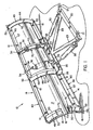
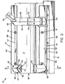
- the clearing device 10 shown in FIGS. 1, 2 and 3 has in generally a frame structure 14, one at the bottom of the frame 14 attached scratch sheet 16 and a concave to the front and inwardly curved scraper 18.
- the concave curve Clearing board 18 has a front end pointing in the direction of travel or clearing Surface 19 and a rear, the frame 14 facing Area 17 (back).
- the definitions used here are to be understood as follows: “Scratching Blade” is the interchangeable, lower edge section of the clearing device meant while Sheet “the concavely curved frontal surface 19 of the clearing board 18th and the scraper blade 16. Under plow or clearing device 10 are the frame 14, the clearing board 18 and the scraper blade 16 to understand.
- auxiliary elements include a support crossbeam 20, which with Suspensions 21 is provided on a vehicle, not shown are attached. Extend from the support crossbeam 20 struts 23 that pivot at 25 on a box-shaped Frame 26 are articulated.
- the box-shaped frame 26 is by means of a pivot connection 28 pivotable on the bottom portion the frame structure 14 attached.
- the pivot connection 28 allows forward or backward tilting of the Clearing device 10 about a horizontal axis.
- Cylinder 30, the side are mounted on the struts 23, allow a horizontal Swiveling the plow 10 about the swivel suspension 25, so that the angle of inclination of the plow 10 relative to Vehicle (or the direction of travel) can be adjusted to Snow to one side or to the other side of the plow 10 to be able to leave.
- a first mounting arm 33 attached to the box-like frame 26 is attached, and a second mounting arm 34, the attached to the upper end of the frame structure 14 serve for mounting one or more springs 36, which the clearing device 10 keep in an upright position. If the scratch sheet 16 on a Hitting an obstacle on the road, etc., the plow 10 swings the pivot 28 against the force of the springs 36 that the clearing device or the plow 10 after passing the obstacle in his Move the normal position back. The tension of the springs 36 is in in a known manner by means of screwed into the mounting arms 34 Adjustment arms 38 set.
- auxiliary elements described above are for generic Plows are known and therefore need no further explanation become. It should be noted, however, that it is lightweight Clearing board 18 is made possible, the auxiliary elements as well to construct the frame 14 in a manner that the Weight and manufacturing costs compared to building this Components in conventional steel clearing boards can be reduced can.
- the frame 14 shown in Figs. 1, 2 and 3 is similar constructed like a conventional frame for a snow clearing plow with steel clearing board.
- the scope of the invention but should not exclusively be based on a special frame construction be limited.
- the frame 14 a longitudinally extending upper mounting member 40 that A lower mounting element extends across the full width of the plow 41, which extends accordingly over the width of the plow, as well as several spaced apart and over the Width of the plow side by side, concave curved Cross struts 44, which are between the upper mounting member 40 and the lower mounting element 41 and extend to this are attached.
- the upper mounting element is usually an angle profile with a mounting leg 47 and one in the right Angle to this essentially radially extending Leg 48.
- the cross struts 44 are also here, as shown in the drawings to make angle profiles with a V-shaped Cross-section.
- the legs 49 of the "V" end in concave curved front end faces 50, the curvature of the Cross struts or the end faces similar to the curvature of the concave curved clearing board 18 is executed.
- the end faces 50 of the cross struts 44 are curved in an arc and have a radius of curvature that matches the radius of curvature of the Clearing boards 18 is adapted.
- Each cross strut 44 has an upper angle profile end 52, the cut along a radial line or a radial plane is through the center of the curvature of the front face 50 goes.
- the radially extending leg 48 of the Upper mounting element 40 is aligned with the upper end of the angle 52 created and welded to this, so that with this coplanar contact line the position of the fastening leg 47 is ensured relative to the clearing board 18.
- each cross strut 44 is cut in a similar manner, preferably along a radial plane through the Center of the radius of curvature of the front face 50 passes.
- the lower mounting member 41 has in the preferred Embodiment a lower angle profile 56 and a flat Mounting plate 57, which is preferably on the radially extending leg 60 of the angle profile 56 abuts so that the mounting leg 59 of the angle profile 56 and the mounting plate 57 are essentially coplanar.
- the frame 14 is composed in that the angle profiles be cut precisely so that the cross struts 44th are bent with the desired radius of curvature and that using conventional stops or fittings to keep the elements in their exact assignment to each other, the elements are welded together.
- FIGS. 1, 2 and 3 Frame around a conventional frame.
- the general structure of all frames is similar in some points. So there are preferably at least four cross struts 44 on at least one, but preferably two (upper and lower) Mounting plates (longitudinal struts) attached.
- the profile shapes of the mounting plates and cross struts can vary.
- the clearing board 18 is preferably made of a polyethylene plastic with ultra high molecular weight (UHMW: ultra high molecular weight) and is usually 9.55 mm thick (3/8 ").
- UHMW ultra high molecular weight
- a suitable UHMW plastic is among the registered Brand names HOSTALEN GUR412LS and GUR422 distributed and is available from Hoechst (in America).
- the UHMW polyethylene material has a very low coefficient of friction, a relatively high abrasion resistance and sufficient flexural strength and thermal stretch limit to Snow clearance conditions to work. With the preferred Embodiment, the material is initially flat Sheet material into the curved one shown in the drawings Arrangement rolled or rolled. The material would be without a support this curved shape does not last for an extended period of time maintained.
- FIGS. 1 to 3 Frame 14 the clearing board 18 on the upper fastening leg 47 and on the lower mounting plate 57 by means of Fasteners 61 mounted, preferably a Have square shank, preferably through square holes fits in the clearing board 18.
- cross struts 44 for a curved support of the clearing board 18 care when the plow is in use, taking the scraper the opportunity is open to himself during his deployment bend or "jump" to the operation of the plow to improve.
- gap X in the preferred embodiment appropriately designed such that it is between a minimal Distance near the top portion of the clearing board 18 and one maximum distance near the lower portion of the clearing board 18 varies, i.e. resembles half a sickle.
- Gaps can cause the clearing board to jump or bend over one wide area of the clearing board can be controlled, resulting in a improved application behavior of the clearing board when rolling up and Lateral removal of the snow with the front Surface 19 leads.
- FIGS. 21 and 22 The features of the plow described so far are known as also shown in FIGS. 21 and 22, in which the described Arrangement from the prior art is shown.
- the vertically extending gap i.e. the space between the clearing board 18 and the section thereof facing the Cross strut 44 can be clearly seen in FIG. 21 as distance X. 22 is shown even more clearly in the cross-sectional view, that the gap X is the distance between the Back 17 of the clearing board 18 and the curved front face 50 of the leg 49 of the cross strut 44 is. That gap X starts bending the clearing board 18 in operation.
- Foreign material which is provided with the reference symbol 62 in FIG. 21, collects in gap X and fills it up. This foreign material gets between the legs 49 of the cross strut 44 and is jammed there.
- the foreign material can not only street dirt, but also ice formations or chunks of ice, when operating the plow in severe weather conditions may occur.
- the foreign particles prevent the desired one Deflection of the clearing board 18 or leave the desired one Deflection only partially.
- the plow 10 is therefore due to the low friction properties of the clearing board 18 made of polyethylene even with the jammed foreign material work and work better than plows with conventional ones Steel sheets are equipped.
- clearing boards are thwarted or reduced.
- FIGS. 1 to 6 provided that a body made of elastic or elastically deformable material 70 between the cross strut 44 and the clearing board 18 is inserted such that at least one Section of the gap X filled with the elastic material is.
- any block or solid-like, elastic or flexible material be understood, even at the temperatures that the clearing device or plow 10 is normally exposed, maintains a degree of elasticity. With elasticity is the property of the material meant to act under force deform and resume the original shape, when the force ceases. The elastically deformable material "springs" back to its original shape.
- elastic deformable material includes natural elastic materials, thermosetting materials and thermoplastics, in particular those characterized as natural or synthetic elastomers are or the natural or synthetic elastomers contain as constituents, polymers or composite materials thereof, including but not limited to natural rubber, Fluorine elastomers, polyurethane elastomers, styrene butadiene rubber, CIS-1,4-polybutaties, CIS-1,4, polyisoprene, butyl rubber, Ethylene propylene polymer, ethylene butyl polymer, neoprene, Nitrile rubber, silicone rubber, polysulfide rubber, Polyacrylate rubber and thermoplastic polyolefins.
- natural rubber Fluorine elastomers, polyurethane elastomers, styrene butadiene rubber, CIS-1,4-polybutaties, CIS-1,4, polyisoprene, butyl rubber, Ethylene propylene polymer, ethylene
- Elastic deformable material should also include liquid Foams and sprays that become flexible, elastically deformable solid-like materials in dried or hardened Solidify condition, as well as polymer foams and in particular one- or two-component, flexible polyurethane foams understood that are particularly suitable for retrofitting.
- the elastically deformable Material a thermoplastic elastomer, which is under the brand name Santoprene 101-64 available from Mile Rubber & Packaging Co. is. This material has a degree of compression of approximately 23% at 25 ° C and an elongation limit of about 400%.
- the Test hardness is about 50 (the usable hardness range is between 20 and 80, preferably between 40 to 60) and the material shows no brittle fracture at low temperatures.
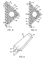
- the elastically deformable material 70 has a triangular shape Blocks 72 with one extending through the block central, cylindrical opening 73.
- the triangular block is dimensioned such that it is between the legs 49 of the Cross strut 44 fits into it.
- the triangular block 72 extends in the idle state of the Plow 10 beyond the curved front faces 50, to completely fill the gap X and the rear or rear surface 17 of the clearing board 18 touch.
- Fig. 6 it can be clearly seen that the outer surfaces of the triangular block 72 are straight.
- the length dimension of the triangular Blocks 72 are larger than the vertically extending curved one Length over which the clearing board 18 bends, and this The length of the block is designated by the reference symbol Y in FIG. 6.
- Reference character "Y" is used throughout the description, around the vertical longitudinal extent of the elastically deformable To designate material 70 in the gap X.
- the excess material or the end regions 74 (only one end region 74 is shown in FIG.
- FIGS. 1 to 6 shows the triangular block 72 in contact with the back 17 of the Clearing boards across the vertical length Y of the gap X. This is only for drawing and illustration purposes. Indeed the triangular block 72 does not or need not necessarily the back 17 of the clearing board 18 over the Touch the vertical length Y of the gap X.
- FIGS. 4A and 5A show an alternative embodiment the invention in a representation that corresponds to FIGS. 4 and 5.
- the triangular block 72 is all over itself vertically extending longitudinal dimension Y changed to smaller To have outer surface dimensions. Even the modified block 72A has a central cylindrical passage 73A.
- the end sections 74 of the modified block 72A are like the triangular one Block 72 is formed for the aforementioned purposes.
- There the changed block 72A extends in the gap X, the Gap X reduced by an amount that in the drawing with the reference symbol A is designated in FIGS. 4A and 5A, this Distance A between the back 17 of the clearing board and one front outer surface 75 formed on the modified block 72A is.
- Gap A can get foreign material like road debris, here with Reference number 62 denotes, or ice plates, here with reference numbers 64 labeled collect.
- the gap X is consequently thereby completely filled in that foreign material 62, 64 before modified block 72A protrudes. If the arrow in Fig. 5A shown snow force on the front surface 19 of the Clearing board 18 acts, the clearing board 18 can still bend resiliently and the gap X to the dimension X ', as shown out.
- the reduced gap X 'in FIG. 5A is larger than the reduced gap X 'in Fig. 5, but the scraper board is further able to bend and as a result suitable the roll-up and lateral removal movement of the Improve snow over its area.
- the invention is therefore not necessarily limited to that elastically deformable material fills the gap X, because that Clearing board still according to its design advantages will bend or jump if elastically deformable material 70 the gap X as shown in FIGS. 4A and 5A only partially filled. It is understood that the suspension quality of the clearing board 18 is optimized when the elastically deformable Material 70 essentially completely fills the gap.
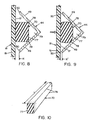
- FIG. 6 Another modification of the triangular block 72 is with the triangular block 72B shown in FIG.
- the additional Change is the removal of the end portions 74 of the triangular block 72 which, as with reference to FIG 1 to 6 has been explained, between the cross strut 44 and the upper fastening leg 47 on the one hand and between the cross strut 44 and the lower mounting plate 57 is clamped.
- the modified block 72B therefore only extends over the length Y as shown in Fig. 6. Hold the legs 49 of the cross strut 44 the modified triangular block 72B within the Cross strut 44 fixed.
- a rectangular block made of elastically deformable Material 70 has.
- the rectangular block is 77 dimensioned such that it extends over a length Y or alternatively extends over a greater length to the one hand the radial extending leg 48 of the upper mounting element 40 and on the other hand the radially extending lower leg 60 of the lower mounting element 41 in the assembled rest position to touch.
- the cross section of the rectangular block 77 is dimensioned such that the two rear edges 78 touch the V-leg 49 of the cross strut 44, while doing so a sealed cavity 79 between the rectangular Release block 77 and the crown of the cross strut in the Foreign material cannot enter.
- the vertex cavity 79 enables a deformation of the elastically deformable material of the rectangular block 77 when the scraper 18, such as shown in Fig. 9 bends regardless of the presence of any Foreign material between the leg end faces 50, the clearing board 18 and the rectangular block 77.
- Embodiments has the elastically deformable material Form of an elastically deformable strip 80.
- the elastic deformable strip 80 is on one side of a double-sided Adhesive tape 81 attached, which is preferably a elastically deformable coated on both sides with an adhesive or damping material.
- the other side of the double-sided Band 81 is attached to the back 17 of the clearing board 18.
- the band 81 and the one have elastically deformable Strips 80 together a thickness slightly larger than the gap is X, so that in the assembled idle state, like it is shown in Fig. 12, the front curved end faces 50 of the cross strut 44 touch the strip 80 firmly.
- the double-sided Band 81 enables precise positioning of the elastic deformable strip 80 for the installation of the clearing board 18 in the frame 14. Depending on the assembly technology, this can double-sided adhesive tape 81 replaced by other assembly techniques become. Alternatively, the elastically deformable material of the double-sided adhesive tape 81 alone the elastically deformable Form material 70 and a separate or additional damping Strip 81 (with an adhesive coating on only one side) can replace the elastically deformable strip 80. The elastic deformable strips 80 can also just instead with an adhesive layer for attachment to the back 17 of the Clearing boards can be coated. From Fig. 11 it is clear that the Length Y of the elastically deformable strip 80 is not greater can be as the distance between the exposed edge of the upper mounting leg 47 and the exposed edge of the lower mounting plate 57.
- FIGS. 1 to 17 Another embodiment of the invention is in 13 to 17 shown.
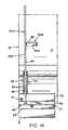
- the one shown in Figs. 13 and 14 Frame 14A has one of frame 14 of FIGS. 1 through 12 different structure, but is in the essential elements as the frame described above, so that the Description of the frame 14A shown in Figs. 13 and 14 for same components same reference numerals as in the description of the frame 14 can be used in FIGS. 1 to 3.
- the cross strut 44A has no V-shape, but is included as a flat plate executed only one leg 49A, the front or front End face 50A is curved.
- the cross strut 44A is on one locked lower mounting member 41, which, as described, has an angle profile 56 and a flat lower mounting plate 57.
- the upper mounting element 40A (now in the form of segments between adjacent cross struts 44A) is approximately in the middle, i.e. halfway up the Cross brace 44A positioned with its mounting leg 47A and its radially extending leg 48A with the Leg 49A of the cross strut 44A are welded, as with Reference numeral 83 in Fig. 14 is indicated.
- the cross strut 44A therefore differs from the cross strut described above 44 through an upper end region 84, which extends radially extending leg 48A protrudes. It is more important that the cross strut 44A of that described in FIGS. 1 to 12 Cross strut 44 differs in that the front curved Face 50A a progressively increasing gap X between itself and the rear surface 17 of the clearing board 18.
- the progressive gap X is in that assembled hibernation right from the start in the frame construction constructed so that the clearing board 18 a little Bounce back or bend at its top section and a significantly greater bending at its lower, transversely extending Section can have.
- the intentional one Gap improves the property of the plow, the snow in roll up the curvature of the clearing board 18.
- the provision of one increasing gap is known in itself.
- the increasing gap X serves its intended purpose. It is understood that the Gap X on purpose (as in this embodiment) or at random (as in the embodiments in FIGS. 1 to 12) due to of manufacturing tolerances, the assembly process etc. non-uniform can be.
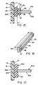
- the elastically deformable material 70 is in the form of a grooved Strip 85 with a formed on one of its sides, extending groove or channel 86.
- the Groove 86 has side walls 87 which define the leg 49A of the cross strut 44A, and a groove base 88 which is in contact with the front curved end surface 50A of the cross strut 44A.
- the Grooved strip 85 is preferably dimensioned such that its thickness between an outer strip back 89, which the back surface 17 of the clearing board 18 is opposite, and the Groove bottom 88 varies progressively according to the gap X. An important difference is that that shown as dimension Y in FIG.
- the length of the grooved strip 85 in the gap X is not the vertical length of the clearing board 18 as in the previously described Embodiments must correspond.
- the trained as an increasing gap ensures Gap X bending the clearing board 18 over its lower itself transversely extending section. Accordingly, the grooved needs Strip 85 only over the lower section of the cross strut 44A to accommodate the bending of the clearing board this scraper section, as shown in Figs. 13 and 14, sure.
- a collection of foreign material in the section of the gap X, which is not partially or completely with elastically deformable material 70 is filled, the desired Do not negatively affect the operation of the plow 10.
- Strip 85A in Fig. 17 is a modification of the grooved strip 85 shown, which to that explained with reference to FIGS. 11 and 12 and described embodiment is based.
- Strip 85A in Fig. 17 the groove is omitted.
- the stripe 85A can be attached to the rear surface 17 of the clearing board 18 a double-sided adhesive tape 81 (not shown) or by means of an adhesive coating on the outer strip back 89A be attached.
- FIGS. 1 to 12 the frame in Fig. 18 is with the frame 14 according to FIGS. 1 to 12 almost identical. Extends differently the fastening leg 47 of the upper mounting element 40 vertically upwards and not, as in FIGS. 1 to 12, in the vertical direction downward. This is only intended to illustrate that 14 variations are possible with the frame. It is not for any of them in both embodiments, the alignment of the top Mounting element 40 to change to an elastically deformable material in a deliberately constructed, varying gap X, as shown in Fig. 13 apply. With Fig. 18 clarifies that the concave, i.e.
- the triangular block 72A shown in Fig. 19 has a thickness which preferably extends from its upper end 89 to its lower End 90, adapted to the increasing change in gap X, reduced. This dimensional coordination is preferred, for functionality as shown in the 4A and 5A, this is not necessary and the width of the triangular blocks 72A could be constant.
- Fig. 19 shows also that the triangular block is one extending inside may have central opening 73A.
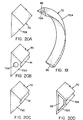
- 20A, 20B, 20C and 20D are alternative embodiments of the elastically deformable material 70 in shape of modified triangular blocks 72.
- a solid triangular block 72B is shown. If the scraper 18 bends, the elastically deformable Material spread on both sides of the cross strut 44, wherein the elastically deformable material behind the front curved end face 50 bulges.
- the dimensionally stable shown in Fig. 20 C. triangular block 72C has one in its apex trained semicircular extending over its entire length Throat 91.
- triangular block 72D is a combination of the triangular blocks 72A and 72C.
- 20C is a triangular block 72E shown which is a central triangular Has recess 93, the outer surfaces of the triangular Blocks 72E as wall sections with substantially the same Thicknesses are formed.
- the recess 93 is not complete triangular, as optional a semicircular throat 91A may be provided in the apex, as is related to FIG 20C has been explained, so that a semicircular wall section is formed in the recess 93.
- the selection of the special construction depends on various factors including the dimensions of the elastically deformable mass and the properties of the selected elastically deformable Material.
- the elastically deformable material should be of its Hardness and bending stiffness should not be such that bending of the clearing board 18 is prevented, but the elastically deformable Material should preferably allow that Bend the clearing board 18 in the same or approximately the same dimensions as if there was no foreign material in gap X.
- the elastically deformable material 70 must be sufficient Have stability that is a build-up of foreign material completely prevented in gap X or prevented as far as that the gap X is only to a certain extent with foreign material crowded.
- the construction of the body of the elastically deformable Material as through the numerous embodiments has been disclosed taking these considerations into account.
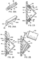
- the 23 and 23A, 24 and 24A and 25 are embodiments shown for retrofit applications of the invention.
- the 23 and 23A disclose an elastically deformable insert 94, which is U-shaped and has a longitudinal groove 95, the The bottom of the "U” touches the clearing board 18 or alternatively at least fills a section of the gap X.
- the cross strut 44 is a Angular profile with frontal end faces 50 that are desired Curvature are cut. 23 is can be seen that the front face 50A of each Leg 49 of the cross strut is provided with an oblique edge. This inclined edge matches the inclined groove base 96 in the groove 95 of the elastically deformable insert 94.
- This Design enables the side walls 97, 98 of the Let groove 95 spread open so that the elastically deformable insert 94 are clamped onto the leg 49 of the cross strut 44 can.
- the sole of the U-shaped, elastically deformable insert 94 is then pressed against the rear surface 17 of the clearing board, so that the sloping groove bottom 96 clinging against the front face 50A of the leg 49 creates.
- FIGS 23 and 23A Another elastically deformable insert 94A for retrofitting is shown in Figures 24 and 24A.
- the elastically deformable Insert 94A has two tapered outer surfaces 100, 101 converging at the tip 102 and a wedge-shaped form elastically deformable insert.
- One outer surface 100 is facing the rear surface 17 of the clearing board and the other outer surface 101 includes a groove 95A which is like that in FIGS 23 and 23A shown and described groove of the elastically deformable Insert 94 is formed.
- the wedge shape of the elastic deformable insert 34A allows a comparative easy retrofitting. It is understood that neither the elastic deformable insert 94 or insert 94A on the retrofit application are limited, but also as elastically deformable Material can be used with new plows.
- Fig. 25 shows still another embodiment, which under the inventive definition of an elastically deformable material falls.
- this embodiment which is particularly for Is suitable cross struts that have an angle profile structure, is the gap X on one side of the cross strut 44 by means of a removable clip or other suitable sheet or bar temporarily closed while in the interior of the Cross strut 44 from the other, open side of the cross strut 44 forth from a foam container 105 an expandable polymer Foam is injected.
- the volume changes of the foam which as a liquid from the pressurized Container 105 is released when it meets Humidity in a foam covering the interior of the cross brace 44 completely filled out.
- a coarse-celled or flexible Foam is used so that the foam has the desired suspension properties to expand and contract.
- the degree the flexibility of the foam depends on its composition from. For example, known one-component or two-component flexible polyurethane foams can be used.
- the previously described Configurations of the elastically deformable material Have a size that extends laterally beyond the gap X (likewise as within) or optionally behind the gap extends.
- the composition of elastically deformable Material within each of the "blocks" from the for different "blocks” disclosed material or structure varies not only the accumulation of foreign material in the Gap is prevented, but this also becomes a desired one Deflection movement of the clearing board leads.
- the cross strut 44 can also be an "L-profile", “U-profile” or “H-profile” or the cross strut is manufactured in a different way.
Landscapes
- Architecture (AREA)
- Civil Engineering (AREA)
- Structural Engineering (AREA)
- Engineering & Computer Science (AREA)
- Soil Working Implements (AREA)
- Road Paving Structures (AREA)
- Cleaning Of Streets, Tracks, Or Beaches (AREA)
- Auxiliary Devices For And Details Of Packaging Control (AREA)
- Knives (AREA)
- Distribution Board (AREA)
- Control And Other Processes For Unpacking Of Materials (AREA)
- Paper (AREA)
- Storage Of Harvested Produce (AREA)
- Shielding Devices Or Components To Electric Or Magnetic Fields (AREA)
- Disintegrating Or Milling (AREA)
Abstract
Description
Die Erfindung betrifft ganz allgemein Räumgeräte und insbesondere eine Verbesserung eines Räumgerätes und ähnlicher Vorrichtungen zum Räumen von Schnee und anderer Aufschüttungen, von Straßen, Wegen und ähnlichen Oberflächen.The invention relates generally to clearing devices and in particular an improvement of a clearing device and similar devices for clearing snow and other fillings, of roads, paths and similar surfaces.
Die Erfindung ist insbesondere anwendbar für Schneepflüge, wobei ein verbesserter Pflug bzw. Räumgerät geschaffen wird. Die Erfindung wird im folgenden mit Bezug auf ein Schneeräumgerät beschrieben. Die Erfindung kann jedoch auch bei anderen Räumgeräten oder Pflügen, die z.B. in der Landwirtschaft eingesetzt werden, Anwendung finden.The invention is particularly applicable to snow plows, whereby an improved plow or clearing device is created. The invention is described below with reference to a snow removal device described. However, the invention can be used in others Broaches or plows, e.g. used in agriculture will find application.
Die beiden US-Patente US 4,845,866, erteilt am 11.07.1989 und US 5,088,215, erteilt am 18.02.1992, enthalten die Hintergrundinformationen für die vorliegende Erfindung. Auf Details der in diesen Patenten beschriebenen Pflugkonstruktion wird nicht weiter eingegangen.The two US patents US 4,845,866, issued July 11, 1989 and US 5,088,215, issued February 18, 1992 contain the background information for the present invention. On details the plow construction described in these patents not discussed further.
Ein Pflug als Schneeräumgerät zum Räumen bzw. Entfernen des Schnees von Straßen weist eine Schaufel auf, die den Schnee aufrollt und anschließend quer zur Frontfläche der Schaufel bewegt. Um dies zu bewerkstelligen, weist das Räumgerät ein Räumbrett mit gekrümmtem Aufbau auf, das unten in einer unteren Räumkante oder einem Kratzerblatt endet. Das Kratzerblatt erstreckt sich normalerweise in Fahrtrichtung nach vorne, um sich in den Schnee einzugraben und den Schnee in das gekrümmte Räumbrett hineinzuzwängen. Die Kontur des Räumbretts leitet einen Drall in den sich aufwärtsbewegenden Schnee ein und zwängt den Schnee über die Frontseite des Räumbretts quer zur Seite des Räumgerätes ab. A plow as a snow clearing device for clearing or removing of snow from streets has a shovel that Snow rolls up and then across the front of the Shovel moves. To do this, the clearing device a scraper with a curved structure on the bottom in a lower clearing edge or a scraper blade ends. The Scraper blade usually extends in the direction of travel forward to dig into the snow and the snow to squeeze into the curved scraper. The contour of the Clearing boards conduct a twist in the upward moving Snow and forcing the snow over the front of the clearing board across to the side of the clearing device.
Im Laufe der Zeit wurden eine Vielzahl von Räumbrettkonfigurationen mit verschiedenen Kurvenformen ausprobiert, bis eine Form gefunden wurde, die ein gleichmäßiges Aufrollen und Querbewegen sowohl von nassem als auch pulverigem Schnee quer zur Frontfläche des Räumbretts sicherstellt. Eine solche Räumbrettkurve, die im wesentlichen bogenförmig ist und sich in nur einer Krümmungsebene erstreckt, hat sich als akzeptable, weithin verwendete geometrische Konfiguration für das Räumbrett bewährt.Over time, a variety of dozer configurations have been developed tried with different curve shapes until one Form was found that rolled up and moved smoothly of both wet and powdery snow across the Ensures the front surface of the clearing board. Such a clearing board curve, which is essentially arcuate and is in only one Plane of curvature has been found to be acceptable, widely used Tried and tested geometrical configuration for the dozer board.
Eine typische Schneeräumbrettkonstruktion besteht darin, eine Platte aus niedrig gekohltem Stahl, gewöhnlich mit einer Dikke von etwa 3,2 mm (1/8"),in eine Bogenform zu walzen, um das Räumbrett auszubilden. Die Rahmenkonstruktion, die gewöhnlich aus Winkelprofilbauteilen konstruiert ist, wird anschließend an der Rückseite des Räumbretts angeschweißt, um dieses abzustützen und zu verhindern, daß das Räumbrett bricht oder knickt, wenn es auf Steine oder andere Aufhäufungen auf der Straße trifft, wobei die Rahmenkonstruktion auch zur Befestigung der für den Betrieb des Räumgeräts notwendigen Komponenten dient. Beispiele für derartige Konstruktionen finden sich in den Patenten US 3,432,947 und US 3,465,456, die auf die Anmelderin überschrieben wurden.A typical snow plow construction is one Low carbon steel plate, usually with a thickness of about 3.2 mm (1/8 ") into an arc shape to make the Training clearing board. The frame construction, the usual is constructed from angle profile components, is then welded to the back of the clearing board to support it and to prevent the scraper from breaking or kinking when it does hits stones or other piles on the street, whereby the frame construction also for fastening the for operation necessary components of the clearing device. Examples of such Constructions can be found in patents US 3,432,947 and US 3,465,456, which have been assigned to the applicant.
Wegen seines großen Gewichts ist ein Räumbrett aus Stahl nicht wünschenswert. Ein Stahlräumbrett bedingt höhere Beanspruchungen an das Fahrzeug, an dem es befestigt ist, und insbesondere erfordert es eine stärkere Räumgerätbefestigung und größere Hebesysteme, als sonst möglich wären.Because of its great weight, a clearing board is made of steel not desirable. A steel clearing board requires higher loads the vehicle to which it is attached, and in particular it requires a stronger broach attachment and larger ones Lifting systems than would otherwise be possible.
Es wurden eine Reihe von Versuchen unternommen, die Effizienz des Stahlräumbretts in den vorgenannten Pflügen zu steigern, um die Rollbewegung und die Querbewegung des Schnees quer zur Frontseite des Räumbretts zu verbessern. Viele dieser Vorschläge sehen eine Erniedrigung des Reibungskoeffizienten an der Frontfläche des Räumbretts vor. Beispielsweise wurde von den Schneepflugbetreibern lange Zeit ein auf den Räumbrettern aufgetragenes Wachs verwendet. Räumbretter wurden auch mit verschiedenen Substanzen dauerhaft beschichtet. Solche Beschichtungen versagen jedoch, wenn sie durch Steine, Felsbrocken und anderen Straßenschutt, die mit hoher Wucht auf das Räumbrett stoßen, abgeschlagen werden. A number of attempts have been made to improve efficiency of the steel clearing board in the aforementioned plows, to the rolling movement and the transverse movement of the snow across To improve the front of the clearing board. Many of these suggestions see a reduction in the coefficient of friction on the front surface of the clearing board. For example, the snow plow operators for a long time a plotted on the clearing boards Wax used. Clearing boards were also made with different ones Substances permanently coated. Such coatings fail however, when going through stones, boulders and other road debris, who hit the scraper with great force, knocked off become.
Im Stand der Technik gibt es eine Vielzahl verschiedener Materialien mit extrem niedrigem Reibungskoeffizienten. Insbesondere wurde ein Polyethylen mit ultrahohem Molekulargewicht entwickelt und dort industriell eingesetzt, wo es auf einen Gleitkontakt ankommt, wie bei Gleitstreifen, Gleitplatten, Gleitlager oder Lagerschalen. Bis vor einiger Zeit war die Ansicht verbreitet, daß wegen der mechanischen Eigenschaften derartiger Materialien ein Einsatz als Räumbretter in Schneeräumgerätanwendungen ausgeschlossen ist.There are a variety of different materials in the prior art with extremely low coefficient of friction. In particular developed an ultra high molecular weight polyethylene and used industrially where there is a sliding contact arrives, as with slide strips, slide plates, slide bearings or bearing shells. Until a while ago, the view was widespread that because of the mechanical properties of such materials use as a clearing board in snow clearing applications is excluded.
Aus Erwägungen zum Gewicht und den Kosten wurden für die Räumbretter von Schneepflügen verschiedene Kunststoffmaterialien eingesetzt, aber keine Polyethylene mit ultrahohem Molekulargewicht. Diese Kunststoffe wurden mit der gewünschten Kurvenform vorgeformt und stumpf aufliegend an dem Rahmen angebracht, wo sie vor Ort gebohrt und in gleicher Weise befestigt wurden, wie die Stahlräumbretter konventionell am Rahmen angebracht wurden. Abhängig von den Eigenschaften des Kunststoffs und seiner Dauerbeständigkeit haben Kunststoffräumbretter begrenzten Erfolg gehabt.Considerations of weight and cost were used for the Snow plow clearing boards various plastic materials used, but no ultra high molecular weight polyethylenes. These plastics were made with the desired curve shape preformed and butt-fitting attached to the frame where they were drilled on site and fastened in the same way as the steel clearing boards were conventionally attached to the frame. Depending on the properties of the plastic and its durability plastic clearing boards have had limited success.
Die Schneepflüge wurden signifikant verbessert, als ein Polyethylenmaterial mit hochmolekularem Gewicht als Räumbrett verwendet wurde, um einen dauerbeständigen, leichtgewichtigen und signifikant verbessertes Schneeräumpflug zu schaffen, wie er in den Patenten US 4,803,790 und US 4,845,866 offenbart ist. Das in dem US-Patent 4,803,790 offenbarte Räumgerät weist einen konventionellen Rahmen auf, der obere und untere sich längs erstrekkende Montageelemente mit annähernd gleicher Länge wie die Pflugschaufel und eine Vielzahl von vertikal sich erstreckenden, quer beabstandeten Querstreben aufweist. Jede Querstrebe ist mit ihrem einen Ende an dem oberen Montageelement und mit ihrem anderen Ende an dem unteren Montageelement befestigt und hat eine konkav (nach innen) gekrümmte, frontseitige Stirnfläche, die sich zwischen dem oberen und dem unteren Montageelement erstreckt. Ein im wesentlichen rechteckförmiges und konkav gekrümmtes Räumbrett aus Polyethylen mit hohem Molekulargewicht ist mittels Schraubbefestigungsmitteln an dem oberen und unteren Montageelement in gekrümmter oder vorverspannter Weise befestigt. Die Rückseite des befestigten Räumbretts hat von den vorderen, in Fahrtrichtung weisenden Stirnflächen der Querstreben einen festen Abstand, so daß zwischen Räumbrett und Querstrebe ein Zwischenraum freibleibt. Dieser Abstand oder Zwischenraum reicht im Normalbetrieb des Räumgeräts aus, einen Kontakt zwischen den Räumbrett bzw. Räumschild und den Querstreben zu verhindern, während bei extremen Schlagstößen durch Aufschüttungen eine Berührung mit den Streben möglich wird. Das Räumbrett biegt sich also federnd in den Zwischenraum hinein oder heraus, wenn schwerer oder nasser Schnee zu räumen ist, und dieses Verbiegen verbessert die Querbewegung und Rollbewegung des Schnees über die Frontfläche des Räumbretts. Bisher sorgen die Rahmen/Räumbrettmontageanordnungen für eine Querabstützung des Räumbretts, um einen Bruch des Räumbretts zu verhindern, wenn das Räumbrett durch schwere Aufschüttungen stoßbeansprucht ist. Daher hat diese Konstruktion für eine erhebliche Verbesserung des Standes der Technik gesorgt.The snow plows have been significantly improved as a polyethylene material with a high molecular weight used as a clearing board has been designed to be durable, lightweight and to create significantly improved snow clearing plows as he does in the patents US 4,803,790 and US 4,845,866. This in U.S. Patent 4,803,790 clearing device has a conventional one Frame on, the upper and lower longitudinally extending Mounting elements with approximately the same length as that Plow shovel and a variety of vertically extending, has transversely spaced transverse struts. Every cross strut is included one end to the top mounting member and the other End attached to the lower mounting element and has one concave (inward) curved front face, the extends between the upper and lower mounting members. An essentially rectangular and concave curve High molecular weight polyethylene scraper is by means of screw fasteners on the upper and lower Mounting element in a curved or prestressed manner attached. The back of the attached clearing board has from the front end faces of the cross struts pointing in the direction of travel a fixed distance, so that between the dozer board and cross strut a space remains free. This distance or space one contact is sufficient in normal operation of the clearing device between the dozer board or dozer blade and the cross struts to prevent during extreme impact impacts from fillings contact with the struts becomes possible. The clearing board bends springily into the space or out when heavy or wet snow needs to be cleared, and this Bending improves the lateral movement and rolling movement of the Snow over the front surface of the snowboard. So far they worry Frame / clearing board mounting arrangements for a transverse support of the Clearing boards to prevent breakage of the clearing board when the clearing board is impacted by heavy fillings. Therefore, this construction has for a significant improvement of the state of the art.
Eine Weiterverbesserung der vorgenannten Anordnung ist im US-Patent 5,088,215 offenbart. In diesem Patent wurde das Räumbrett aus Polyethylen mit hohem Molekulargewicht mit einer gewünschten Krümmung vorgeformt und die oberen und unteren Montageleisten wurden geändert, damit das Räumbrett im bzw. auf dem Rahmen eingeklemmt und mittels üblicher Befestigungsmittel gesichert werden kann. Während bei diesem Patent die Anordnung der Rahmenbefestigung verbessert ist, bleibt der Spalt zwischen dem Räumbrett und den Querstreben erhalten, so daß das Räumbrett auch seine verbesserten Schneeräumcharakteristiken beibehält.A further improvement of the above arrangement is in U.S. Patent 5,088,215. In this patent, the dozer board made of high molecular weight polyethylene with a desired Preformed curvature and the top and bottom mounting rails were changed so that the clearing board in or on the Frame clamped and secured using standard fasteners can be. While in this patent the arrangement of the Frame attachment is improved, the gap remains between the Get the clearing board and the cross struts so that the clearing board also maintains its improved snow clearing characteristics.
Beide Konstruktionen sind nicht nur wegen ihres geringen Gewichts und günstigen Preises erfolgreich, sondern auch wegen der verbesserten Betriebs des Räumbretts, der mit den Materialeigenschaften des Polyethylenmaterials und der Ausnutzung der Fähigkeit des Materials zusammenhängt, sich in den konstruktiv in der Befestigungsanordnung vorgesehenen Zwischenraum hineinzubiegen bzw. zu "springen".Both constructions are not only because of their light weight and cheap price successful, but also because of improved operation of the clearing board with the material properties of the polyethylene material and the exploitation of the ability of the material is related to the constructive in the Bend the mounting arrangement provided space or to "jump".
Schneepflüge werden normalerweise in unwirtlichen Umgebungen eingesetzt und sind tiefen Temperaturen, Feuchtigkeit, Eisregen, Eis, Salz und heftigen Stoßschlägen gegen feste Vorsprünge wie Bordsteine, Felsbrocken und Straßenschutt ausgesetzt. Während des kontinuierlichen oder fortgesetzten Betriebs des Räumgeräts kann Straßenschutt in die Spalte zwischen dem Räumbrett und den Querstreben gelangen und darin steckenbleiben. Falls der Betreiber nicht regelmäßig die Zwischenräume säubert, können diese vollständig mit festem Schutt gefüllt werden, was zur Folge hat, daß der durch den Spalt geschaffene Federweg des Räumbretts an dem Rahmen verlorengeht oder vermindert wird. Noch bedeutsamer ist, daß die Betriebstemperaturen des Räumgeräts eine solche Temperaturspanne zeigen, daß sich Wasser in dem Zwischenraum sammeln und zu Eis, Eisblöcken oder Eiseinschlüssen in den Zwischenräumen erstarren kann. In derartigen Fällen geht der in das Räumbrett/die Rahmenkonstruktion hineinkonstruierte Zwischenraum verloren oder wird drastisch reduziert. Während das Räumbrett dann noch seine verbesserten Schneentfernungseigenschaften aufgrund des niedrigen Reibungskoeffizienten hat, ist die verbesserte Eigenschaft des Räumbretts zum Querbewegen und Aufrollen des Schnees quer zur Frontseite des Räumgeräts vermindert.Snow plows are usually in inhospitable environments used and are low temperatures, moisture, freezing rain, Ice, salt and violent blows like solid protrusions Curbs, boulders and rubble exposed. While the continuous or continued operation of the clearing device can rubble into the gap between the scraper and the road Arrive cross braces and get stuck in them. If the operator not cleaning the gaps regularly, they can completely filled with solid rubble, which means that the spring travel of the clearing board created by the gap the frame is lost or reduced. Even more significant is that the operating temperatures of the clearing device such Temperature ranges show that there is water in the space collect and to ice, ice blocks or ice inclusions in the gaps can freeze. In such cases, it goes into that Clearing board / the space constructed in the frame construction lost or drastically reduced. While the scraper then its improved snow removal properties due to of the low coefficient of friction is the improved Property of the clearing board for moving and rolling up of the snow reduced across the front of the clearing device.
Aufgabe der Erfindung ist es, ein Räumgerät mit einer Befestigungsanordnung für ein Räumbrett oder Räumschild aus Kunststoff zu schaffen, die es ermöglicht, daß das Räumbrett unabhängig von den Betriebsbedingungen, denen das Räumgerät ausgesetzt ist, seine gewünschte federnde bzw. elastische Verbiegbarkeit beibehält.The object of the invention is a clearing device with a fastening arrangement for a clearing board or clearing blade made of plastic to create that allows the scraper board to be independent the operating conditions to which the clearing device is exposed is its desired resilient or elastic bendability maintains.
Diese Aufgabe wird zusammen mit weiteren Vorteilen erfindungsgemäß mit einem an ein Fahrzeug anbaubaren Räumgerät (Pflug) zum Räumen von Schnee, Aufhäufungen und dgl. von Straßen und ähnlichen Oberflächen gelöst, das ein Räumbrett bzw. Räumschild aus Kunststoff und einen mit einer Seite an einem Fahrzeug befestigbaren soliden Rahmen aufweist, an dessen gegenüberliegender Seite das Räumbrett montiert ist. Der Rahmen hat zumindest eine sich im wesentlichen vertikal erstreckende Querstrebe, die von dem Räumbrett mindestens über einen Teilbereich seiner Höhe einen Abstand hält und so zwischen sich und dem Räumbrett einen sich vertikal erstreckenden Zwischenraum bildet. Der Zwischenraum wird zumindest teilweise von einem federnden oder elastisch verformbaren Material ausgefüllt, so daß es dem Räumbrett möglich ist, sich selbst dann federnd zu verbiegen, wenn sich Fremdmaterial, wie z.B. Eisstücke, mit Eiseinschlüssen versetztes Fremdmaterial oder fester Straßenschutt in demjenigen Bereich des Zwischenraumes ansammelt, der nicht mit dem elastisch verformbaren Material gefüllt ist.This task is invented together with further advantages with a broaching device that can be attached to a vehicle (Plow) for clearing snow, piles and the like from roads and similar surfaces solved that a clearing board or dozer blade made of plastic and one with a side on a vehicle attachable solid frame, on the opposite Side the clearing board is mounted. The frame has at least an essentially vertically extending cross strut, that of the scraper at least over a partial area its height keeps a distance and so between itself and the Clearing board forms a vertically extending space. The space is at least partially resilient or elastically deformable material, so that it Is possible to bend resiliently even then, if foreign material such as Pieces of ice, with ice inclusions staggered foreign material or solid road rubble in that Area of the gap that is not elastic with the deformable material is filled.
In der Beschreibung und in den Ansprüchen soll unter "elastisch verformbares Material" jegliches festkörperartiges, elastisches Material verstanden werden, das auch bei den Temperaturen, denen das Räumgerät bzw. der Pflug normalerweise ausgesetzt ist, einen gewissen Grad an Elastizität beibehält. Mit Elastizität ist die Eigenschaft des Materials gemeint, sich unter Krafteinwirkung zu verformen und seine ursprüngliche Form und Abmessungen wieder einzunehmen, wenn die Krafteinwirkung aufhört.In the description and in the claims under "elastic deformable material "any solid-like, elastic Material to be understood, even at temperatures, to which the clearing device or plow is normally exposed maintains a certain degree of elasticity. With elasticity is the property of the material meant to act under force to deform and its original shape and dimensions to resume when the force ceases.
Vorzugsweise weist der Rahmen obere und untere sich längs erstreckende Montageelemente auf, die voneinander mittels mehrerer Querstreben im Vertikalabstand angeordnet sind. Die Querstreben sind nebeneinander entlang der Montageelemente im Abstand voneinander angeordnet, wobei das in den Rahmen eingesetzte Räumbrett mit den Montageelementen verbunden ist. Das Räumbrett und die ihm zugewandten Bereiche einer jeden Querstrebe sind konkav nach vorne bzw. innen gekrümmt, um den Zwischenraum bogenförmig zu begrenzen. Die Krümmung kann gleichmäßig oder ungleichmäßig über die Höhe des Pflugs sein.The frame preferably has an upper and lower length extending mounting elements on each other by means of several Cross struts are arranged at a vertical distance. The cross braces are spaced side by side along the mounting elements arranged from each other, the one inserted into the frame Clearing board is connected to the mounting elements. The clearing board and the areas of each cross strut facing it are concavely curved forward or inward to the space limit arched. The curvature can be even or uneven be over the height of the plow.
Das elastisch verformbare Material kann bei einer Ausführungsform im wesentlichen jeden Zwischenraum ausfüllen, wodurch eine Ansammlung von Fremdmaterial, das die federnde Verbiegung des Räumbretts in dem Zwischenraum verhindert würde, vermieden wird.In one embodiment, the elastically deformable material can essentially fill in every space, whereby a build-up of foreign matter that the resilient bend of the clearing board in the intermediate space would be avoided becomes.
Nach einer besonderen Ausführungsform der Erfindung bestehen
die Querstreben aus Winkelprofilen, wobei jede Querstrebe einen
V-förmigen Querschnitt hat und derart ausgerichtet ist, daß sie
mit den Kanten bzw. der Stirnfläche der die V-Form ausbildenden
Schenkel konkav gekrümmt ist, so daß sich zwischen den Schenkelstirnflächen
und der Rückseite des Räumbretts der gebogene Zwischenraum
ausbildet. Das elastisch verformbare Material ist jeweils
zwischen den Stirnflächen der Schenkel einer jeden Querstrebe
und der Rückseite des in den Rahmen eingebauten Räumbretts
angeordnet und füllt den Spalt bzw. Zwischenraum vollständig
oder teilweise aus. Die Anordnung kann bei verschiedenen
erfindungsgemäßen Ausführungsformen bspw. folgendermaßen getroffen
sein:
Nach einer weiteren erfindungsgemäßen Ausführungsform ist das Räumbrett mittels Befestigungsmitteln an den Montageelementen montiert und das elastisch verformbare Material erstreckt sich über eine Distanz bzw. einen Längenabschnitt, die im wesentlichen gleich groß wie die vertikale Länge des Zwischenraums (oder sogar größer als der Zwischenraum) ist, so daß das elastisch verformbare Material das Räumbrett berührt (oder sogar leicht zusammengepreßt ist), wenn die Befestigungsmittel angezogen sind. Hierdurch kann sichergestellt werden, daß ein Zwischenraum vorhanden ist, wenn das Räumbrett in den Rahmen eingesetzt wird, wodurch jegliche Anhäufung von Material in dem Zwischenraum verhindert wird, während der federnde Einbau des Räumbretts in den Rahmen aufrechterhalten bleibt.According to a further embodiment according to the invention the clearing board by means of fasteners on the mounting elements mounted and the elastically deformable material extends over a distance or a length section that essentially same size as the vertical length of the space (or even larger than the space), so that's elastic deformable material touches (or even touches) the dozer board is slightly compressed) when the fasteners are tightened are. This can ensure that a space is present when the clearing board is inserted into the frame causing any accumulation of material in the space is prevented while the resilient installation of the clearing board is maintained in the frame.
Nach noch einer weiteren Ausgestaltung der Erfindung ist das Räumbrett mittels Befestigungselementen an den Montageelementen befestigt und das elastisch verformbare Material erstreckt sich über eine Länge, die kleiner bzw. kürzer als der Zwischenraum ist, wenn das Räumbrett in den Rahmen eingebaut ist, wobei selbst eine Ansammlung von Fremdmaterial in dem offenen Restraum des nur teilweise gefüllten Zwischenraumes nicht das federnde Verbiegen des Räumbretts in den Zwischenraum hinein verhindert.According to a further embodiment of the invention, this is Clearing board by means of fastening elements on the assembly elements attached and the elastically deformable material extends over a length that is smaller or shorter than the space is when the scraper board is built into the frame, being even a collection of foreign material in the open rest room of the only partially filled space not the resilient one Bending of the clearing board in the space prevented.
Erfindungsgemäß ist auch ein Verfahren zum Zusammensetzen
eines Räumgerätes vorgesehen, daß die Schritte
Es ist daher ein mit der Erfindung erzielter Vorteil, daß ein Räumgerät mit einem in einen Rahmen eingebauten Kunststoffräumbrett geschaffen wird, das sich, unabhängig von einer Ansammlung von Fremdmaterial wie z.B. Eisgebilden zwischen dem Räumbrett und dem Rahmen, federnd verbiegen kann.It is therefore an advantage achieved with the invention that a clearing device with a plastic clearing board built into a frame is created that is independent of one Accumulation of foreign material such as Ice formations between the Clearing board and the frame, can bend resiliently.
Ein weiterer erreichter Vorteil ist, daß ein Räumgerät mit einem in einen Rahmen in federnder Weise eingesetzten Kunststoffräumbrett geschaffen wird, bei dem einerseits eine Ansammlung von Fremdmaterial zwischen dem Räumbrett und dem Rahmen verhindert wird und andererseits es dem Räumbrett ermöglicht ist, die gewünschte federnde Durchbiegungen vollziehen zu können.Another advantage achieved is that a clearing device with a plastic clearing board inserted in a frame in a resilient manner is created, on the one hand, a collection foreign material between the clearing board and the frame is prevented and on the other hand it enables the clearing board is to be able to perform the desired resilient deflections.
Ein wichtiger mit der Erfindung erzielbarer Vorteil ist, daß eine Vorrichtung und ein Verfahren zum Nachrüsten bestehender, ein federnd in einen Rahmen eingebautes Kunststoffräumbrett aufweisender Pflüge bzw. Räumgeräte geschaffen wird, wobei die Befestigungsanordnung von sich aus sicherstellt, daß sich das Räumbrett unabhängig von den aus dem Betrieb des Schneeräumgeräts in harten Umgebungsbedingungen resultierenden ungünstigen Umgebungseinflüssen federnd verbiegen kann.An important advantage achievable with the invention is that a device and a method for retrofitting existing, a resiliently integrated plastic clearing board in a frame Plows or clearers is created, the fastening arrangement on its own ensures that this Dozer regardless of the operation of the snowplough unfavorable resulting in harsh environmental conditions Resiliently bend environmental influences.
Die erfindungsgemäßen Ausführungsformen bieten auch den Vorteil, daß ein Räumgerät mit einem Räumbrett bzw. Räumschild aus Kunststoff geschaffen wird, das sämtliche der zuvor beschriebenen Eigenschaften haben kann, wobei das Räumgerät einfach zusammengebaut und im Bedarfsfalle repariert werden kann.The embodiments according to the invention also offer the advantage that a clearing device with a clearing board or clearing blade Plastic is created that all of the previously described Can have properties, the reamer simply assembled and can be repaired if necessary.
Ein weiterer Vorteil der Erfindung liegt darin, daß ein Räumgerät mit einem Kunststoffräumbrett geschaffen wird, das die zuvor beschriebenen Eigenschaften hat und das vergleichsweise kostengünstig ist.Another advantage of the invention is that a Clearing device is created with a plastic clearing board, which has previously described properties and that comparatively is inexpensive.
Mit der Erfindung wird für ein Schneeräumgeräts auch eine Rahmenkonstruktion für ein Räumbrett aus hochdichtem Polyethylen geschaffen, wobei die Rahmenkonstruktion unabhängig von den mit den unwirtlichen Schneepflugbetriebsbedingungen zusammenhängenden Effekten die gewünschte Durchbiegung des Räumbretts bzw. das Freihalten des gewünschten Federwegs sichert.With the invention also for a snow removal device Frame construction for a clearing board made of high-density polyethylene created, the frame construction regardless of the with the inhospitable snow plow operating conditions Effects the desired deflection of the clearing board or that Keeping the desired travel free.
Diese und weitere Aufgaben und Vorteile der Erfindung werden aus der nachfolgenden detaillierten Beschreibung der Erfindung unter Bezugnahme auf die Zeichnungen deutlich.These and other objects and advantages of the invention will be from the following detailed description of the invention with reference to the drawings.
Die Erfindung kann in verschiedenen Ausführungsformen mit
variierenden Bauelementen und Anordnungen von Bauelementen ausgeführt
werden, wobei bevorzugte Ausführungsformen unter Bezugnahme
auf die beigefügten Zeichnungen nachfolgend beschrieben
werden. In der Zeichnung zeigen:
Es wird nun Bezug genommen auf die Zeichnungen, in denen bevorzugte
Ausführungsformen der Erfindung zu Erläuterungszwecken
gezeigt sind, ohne daß die Darstellungen den Schutzbereich beschränken
sollen. In Fig. 1 ist ein Räumgerät 10 gezeigt, das
zum Räumen von Schnee, Schneeverwehungen u.dgl. von schneebedeckten
Einfahrten, Parkbuchten etc. als Anbaugerät an Motorlastwagen,
Pickup-Fahrzeugen, Allradfahrzeugen u.dgl. eingesetzt
wird und gewöhnlich eine Breite von etwa 2 m (78 inch) hat. Die
breiteren, schwereren Einsatzpflüge von Kommunen oder staatlichen
Straßenbehörden, die zum Räumen von Schnee und Geröll von
Kraftfahrstraßen eingesetzt werden, haben gewöhnlich eine Breite
von etwa 2,30 m (90 inch) und können eine Rahmenkonstruktion
aufweisen, die von der dargestellten abweicht. Der Fachmann
wird erkennen, daß die Erfindung bei großen Pflügen genausogut
wie bei kleinen, hier dargestellten Pflügen, Anwendung finden
kann.Reference is now made to the drawings in which preferred
Embodiments of the invention for illustrative purposes
are shown without the illustrations restricting the scope of protection
should. In Fig. 1, a
Das in den Fig. 1, 2 und 3 gezeigte Räumgerät 10 weist im
allgemeinen eine Rahmenkonstruktion 14, ein am Boden des Rahmens
14 befestigtes Kratzerblatt 16 und ein konkav nach vorne und
nach innen gekrümmtes Räumbrett 18 auf. Das konkav gekrümmte
Räumbrett 18 hat eine vordere, in Fahrt- bzw. Räumrichtung weisende
Fläche 19 und eine rückseitige, dem Rahmen 14 zugewandte
Fläche 17 (Rückseite). Die hier verwendeten Begriffsbestimmungen
sind wie folgt zu verstehen: Mit "Kratzerblatt" ist der austauschbare,
untere Randabschnitt des Räumgeräts gemeint, während
Blatt" die konkav gekrümmte Frontalfläche 19 des Räumbretts 18
und des Kratzerblatts 16 bezeichnet. Unter Pflug bzw. Räumgerät
10 sind der Rahmen 14, das Räumbrett 18 und das Kratzerblatt 16
zu verstehen. Unter "Ruhestellung" soll die Relativlage zwischen
Rahmen 14, Räumbrett 18 und Kratzerblatt 16 verstanden werden,
wenn das Räumgerät 10 zwar zusammengebaut und an einem Fahrzeug
befestigt ist, sich aber nicht im Einsatz zum Räumen von Schnee
u.dgl. befindet, d.h. in Ruhestellung ist. Mit "gebogen" ist eine
federnde Rückwärtsverbiegung des Räumbretts 18 relativ zu dem
Rahmen 14 gemeint.The
An dem Rahmen 14 sind für den Betrieb des Pfluges 10 notwendige
Hilfsaggregate und -elemente angeordnet oder befestigt.
Diese Hilfselemente schließen eine Stütztraverse 20 ein, die mit
Aufhängungen 21 versehen ist, die an einem nicht gezeigten Fahrzeug
befestigt sind. Von der Stütztraverse 20 aus erstrecken
sich Streben 23, die bei 25 schwenkbar an einem kastenförmigen
Gestell 26 angelenkt sind. Das kastenförmige Gestell 26 ist mittels
einer Drehzapfenverbindung 28 schwenkbar an dem Bodenabschnitt
der Rahmenkonstruktion 14 befestigt. Die Drehzapfenverbindung
28 ermöglicht ein Vorwärts- oder Rückwärtskippen des
Räumgerätes 10 um eine horizontale Achse. Zylinder 30, die seitlich
an den Streben 23 montiert sind, ermöglichen ein horizontales
Verschwenken des Pfluges 10 um die Schwenkaufhängung 25, so
daß der Winkel der Schrägstellung des Pfluges 10 relativ zum
Fahrzeug (bzw. zur Fahrtrichtung) verstellt werden kann, um
Schnee zur einen Seite oder zur anderen Seite des Pfluges 10
austreten lassen zu können.On the
Ein erster Befestigungsarm 33, der an dem kastenartigen Gestell
26 befestigt ist, und ein zweiter Befestigungsarm 34, der
am oberen Ende der Rahmenkonstruktion 14 befestigt ist, dienen
zur Montage einer bzw. mehrerer Federn 36, die das Räumgerät 10
in aufrechter Stellung halten. Wenn das Kratzerblatt 16 auf ein
Hindernis auf der Straße etc. trifft, schwenkt der Pflug 10 um
den Drehzapfen 28 gegen die Kraft der Federn 36, die das Räumgerät
bzw. den Pflug 10 nach Passieren des Hindernisses in seine
Normalstellung zurückbewegen. Die Spannung der Federn 36 wird in
an sich bekannter Weise mittels in die Befestigungsarme 34 eingeschraubter
Einstellarme 38 eingestellt.A first mounting
Die zuvor beschriebenen Hilfselemente sind für gattungsgemäße
Pflüge bekannt und brauchen daher nicht näher erläutert zu
werden. Es ist allerdings zu beachten, daß es mit einem leichtgewichtigen
Räumbrett 18 ermöglicht wird, die Hilfselemente sowie
den Rahmen 14 in einer Weise zu konstruieren, bei der das
Gewicht und die Herstellkosten im Vergleich zu dem Aufbau dieser
Bauteile bei konventionellen Stahlräumbrettern reduziert werden
können.The auxiliary elements described above are for generic
Plows are known and therefore need no further explanation
become. It should be noted, however, that it is
Der in den Fig. 1, 2 und 3 gezeigte Rahmen 14 ist ähnlich
aufgebaut wie ein konventioneller Rahmen für einen Schneeräumpflug
mit Räumbrett aus Stahl. Der Schutzbereich der Erfindung
soll aber nicht ausschließlich auf eine spezielle Rahmenkonstruktion
beschränkt sein. Ganz allgemein weist der Rahmen 14
ein sich längs erstreckendes oberes Montageelement 40, das sich
über die volle Breite des Pflugs erstreckt, ein unteres Montageelement
41, das sich entsprechend über die Breite des Pflugs erstreckt,
sowie mehrere voneinander beabstandete und über die
Breite des Pfluges nebeneinander angeordnete, konkav gekrümmte
Querstreben 44 auf, die sich zwischen dem oberen Montagelement
40 und dem unteren Montageelement 41 erstrecken und an diesen
befestigt sind. Meist ist das obere Montageelement ein Winkelprofil
mit einem Befestigungsschenkel 47 und einem im rechten
Winkel zu diesem im wesentlichen radial sich erstreckenden
Schenkel 48. Auch bei den Querstreben 44 handelt es sich hier,
wie in den Zeichnungen gezeigt, um Winkelprofile mit einem V-förmigen
Querschnitt. Die Schenkel 49 des "V" enden in konkav
gekrümmten vorderen Stirnflächen 50, wobei die Krümmung der
Querstreben bzw. der Stirnflächen ähnlich zu der Krümmung des
konkav gekrümmten Räumbretts 18 ausgeführt ist. Vorzugsweise
sind die Stirnflächen 50 der Querstreben 44 bogenförmig gekrümmt
und haben einen Krümmungsradius, der an den Krümmungsradius des
Räumbretts 18 angepaßt ist. Bei der Erfindung können eine Vielzahl
von Rahmen verwendet werden, allerdings muß wenigstens eine
Querstrebe hinter der Rückseite 17 des Räumbretts 18 vorhanden
und im Abstand von dem Räumbrett angeordnet sein. The
Jede Querstrebe 44 hat ein oberes Winkelprofilende 52, das
entlang einer Radiallinie bzw. einer Radialebene zugeschnitten
ist, die durch den Mittelpunkt der Krümmung der vorderen Stirnfläche
50 geht. Der radial sich erstreckende Schenkel 48 des
oberen Montageelementes 40 ist fluchtend gegen das obere Winkelende
52 angelegt und mit diesem verschweißt, so daß mit dieser
koplanaren Kontaktlinie die Lage des Befestigungsschenkels 47
relativ zu dem Räumbrett 18 sichergestellt ist. Durch Veränderung
der Winkelverhältnisse zwischen dem oberen Winkelprofilende
52 der Querstrebe 44 relativ zu dem Krümmungsradius der vorderen
Stirnfläche 50 kann die Anordnung zwischen Räumbrett 18 und vorderer
Stirnfläche 50 variiert werden. Alternativ können auch Anschläge
oder Beschläge verwendet werden, um die Relativlage zwischen
Räumbrett 18 und Rahmen 14 festzulegen. Das untere Winkelprofilende
53 jeder Querstrebe 44 ist in ähnlicher Weise zugeschnitten,
vorzugsweise entlang einer Radialebene, die durch den
Mittelpunkt des Krümmungsradius der frontseitigen Stirnfläche 50
hindurchgeht. Das untere Montageelement 41 weist bei der bevorzugten
Ausführungsform ein unteres Winkelprofil 56 und eine flache
Montageplatte 57 auf, die vorzugsweise an dem radial sich
erstreckenden Schenkel 60 des Winkelprofils 56 anliegt, so daß
der Befestigungsschenkel 59 des Winkelprofils 56 und die Montageplatte
57 im wesentlichen koplanar sind.Each
Der Rahmen 14 wird dadurch zusammengesetzt, daß die Winkelprofile
genauestens zugeschnitten werden, daß die Querstreben 44
mit dem gewünschten Krümmungsradius gebogen werden und daß anschließend,
unter Verwendung herkömmlicher Anschläge oder Beschläge
zum Festhalten der Elemente in ihrer genauen Zuordnung
zueinander, die Elemente fest miteinander verschweißt werden.
Wie gesagt handelt es sich bei dem in Fig. 1, 2 und 3 gezeigten
Rahmen um einen konventionellen Rahmen. Alternativ kann auch der
in dem US-Patent 5,088,215 gezeigte Rahmen verwendet werden. Der
allgemeine Aufbau sämtlicher Rahmen ist in manchen Punkten ähnlich.
So sind vorzugsweise zumindest vier Querstreben 44 an wenigstens
einer, vorzugsweise jedoch an zwei (oberen und unteren)
Montageplatten (Längsstreben) befestigt.
Die Profilformen der Montageplatten und Querstreben können variieren.The
Das Räumbrett 18 besteht vorzugsweise aus einem Polyethylen-Kunststoff
mit ultrahohem Molekulargewicht (UHMW: ultra high molecular
weight) und hat normalerweise eine Dicke von 9,55 mm
(3/8"). Ein geeigneter UHMW-Kunststoff wird unter den registrierten
Markennamen HOSTALEN GUR412LS und GUR422 vertrieben
und ist von der Firma Hoechst (in Amerika) erhältlich. Das UHMW-Polyethylenmaterial
hat einen ausgesprochen niedrigen Reibungskoeffizienten,
einen relativ hohen Abriebswiderstand und eine
ausreichende Biegefestigkeit und Wärmstreckgrenze, um bei
Schneeräumbedingungen funktionieren zu können. Bei der bevorzugten
Ausführungsform wird das Material anfänglich von einem flachen
Blattmaterial in die in den Zeichnungen gezeigte gekrümmte
Anordnung gerollt oder gewalzt. Das Material würde ohne Stützeinrichtung
diese gekrümmte Form nicht über einen längeren Zeitraum
beibehalten. Aus diesem Grunde wurde dieses Material industriell
nur für Führungsmäntel und Gleitringen eingesetzt, bei
denen es angemessen abgestützt ist. Der in den Fig. 1 bis 3 gezeigte
Rahmen oder alternativ der in dem US-Patent Nr. 5,088,215
dargestellte Rahmen stützen das Räumbrett in seinem gewünschten
konkav gekrümmten Zustand. Bei dem in den Fig. 1 bis 3 dargestellten
Rahmen 14 ist das Räumbrett 18 an dem oberen Befestigungsschenkel
47 und an der unteren Befestigungsplatte 57 mittels
Befestigungsmitteln 61 montiert, die vorzugsweise einen
Vierkantschaft aufweisen, der vorzugsweise durch Vierkantlöcher
in dem Räumbrett 18 paßt. Bedeutsam für die Erfindung ist, daß
die Querstreben 44 für eine gekrümmte Abstützung des Räumbretts
18 sorgen, wenn der Pflug im Einsatz ist, wobei dem Räumbrett
die Möglichkeit eröffnet ist, während seines Einsatzes sich zu
verbiegen oder zu "springen", um die Funktionweise des Pfluges
zu verbessern.The clearing
Gemäß der Lehren der Patente US 4,803,790; US 4,845,866 und
US 5,088,215 wird das Verbiegen des Räumbretts durch Vorsehen
eines sich vertikal erstreckenden Zwischenraumes oder Spaltes
zwischen der vorderen, in Fahrtrichtung weisenden Stirnfläche 50
der Querstrebe 44 und der Rückseite 17 des Räumbretts 18 bewerkstelligt.
Dieser Spalt oder Zwischenraum ist vorhanden, wenn das
Räumbrett in der zusammengesetzten bzw. Ruhestellung innerhalb
des Rahmens 14 ist, d.h. wenn der Pflug 10 nicht in Betrieb ist.
Dieser sich vertikal erstreckende Spalt, in den Zeichnungen mit
dem Bezugszeichen "X" versehen, muß nicht notwendigerweise
gleichförmig über seine vertikale Längserstreckung sein. Tatsächlich
ist der Spalt X in der bevorzugten Ausführungsform
zweckmäßig derart ausgebildet, daß er zwischen einem minimalen
Abstand nahe des oberen Abschnitts des Räumbretts 18 und einem
maximalen Abstand nahe des unteren Abschnitts des Räumbretts 18
variiert, d.h. einer halben Sichel ähnelt. Durch Variation des
Spaltes kann das Springen oder Verbiegen des Räumbretts über einen
weiten Bereich des Räumbretts gesteuert werden, was zu einem
verbesserten Einsatzverhalten des Räumbretts beim Aufrollen und
seitlichen Abtransportieren des Schnees mit der frontseitigen
Fläche 19 führt.According to the teachings of patents US 4,803,790; US 4,845,866 and
US 5,088,215 will bend the clearing board by provision
a vertically extending space or gap
between the front end face 50 pointing in the direction of travel
the
Die bisher beschriebenen Merkmale des Pflugs sind bekannt,
wie auch aus den Fig. 21 und 22 hervorgeht, in denen die beschriebene
Anordnung aus dem Stand der Technik dargestellt ist.
Der sich vertikal erstreckende Spalt, d.h. der Zwischenraum zwischen
dem Räumbrett 18 und dem diesem zugewandten Abschnitt der
Querstrebe 44 ist deutlich in Fig. 21 als Abstand X zu erkennen.
Noch deutlicher ist in der Querschnittansicht nach Fig. 22 gezeigt,
daß es sich beim Spalt X um den Abstand zwischen der
Rückseite 17 des Räumbretts 18 und der gekrümmten Frontstirnfläche
50 des Schenkels 49 der Querstrebe 44 handelt. Dieser Spalt
X nimmt das Verbiegen des Räumbretts 18 im Betrieb auf. Fremdmaterial,
das in Fig. 21 mit dem Bezugszeichen 62 versehen ist,
sammelt sich im Spalt X und füllt diesen auf. Dieses Fremdmaterial
gelangt zwischen die Schenkel 49 der Querstrebe 44 und wird
dort eingeklemmt. Bei dem Fremdmaterial kann es sich nicht nur
um Straßendreck, sondern auch um Eisgebilde oder Eisbrocken handeln,
die beim Betrieb des Pflugs bei strengen Witterungsbedingungen
auftreten können. Die Fremdpartikel verhindern die gewünschte
Durchbiegung des Räumbretts 18 oder lassen die gewünschte
Durchbiegung nur teilweise zu. Der Pflug 10 wird daher
aufgrund der niedrigen Reibungseigenschaften des Räumbretts 18
aus Polyethylen selbst mit dem eingeklemmten Fremdmaterial noch
funktionieren und besser funktionieren als Pflüge, die mit konventionellen
Stahlblättern ausgestattet sind. Die mit dem Spalt
X in den Pflug integrierte Verbiege- und Springfunktion des
Räumbretts wird jedoch vereitelt oder vermindert.The features of the plow described so far are known
as also shown in FIGS. 21 and 22, in which the described
Arrangement from the prior art is shown.
The vertically extending gap, i.e. the space between
the clearing
Daher ist, wie auch aus den Fig. 1 bis 6 ersichtlich ist,
erfindungsgemäß vorgesehen, daß ein Körper aus elastischem bzw.
elastisch verformbaren Material 70 zwischen der Querstrebe 44
und dem Räumbrett 18 derart eingesetzt ist, daß zumindest ein
Abschnitt des Spaltes X mit dem elastischen Material ausgefüllt
ist.Therefore, as can also be seen from FIGS. 1 to 6,
according to the invention provided that a body made of elastic or
elastically
In der Beschreibung und in den Ansprüchen soll, wie bereits erwähnt, unter "elastisch verformbares Material" jegliches block- oder festkörperartiges, elastisches bzw. nachgiebiges Material verstanden werden, das auch bei den Temperaturen, denen das Räumgerät bzw. der Pflug 10 normalerweise ausgesetzt ist, einen gewissen Grad an Elastizität beibehält. Mit Elastizität ist die Eigenschaft des Materials gemeint, sich unter Krafteinwirkung zu verformen und die Originalform wieder einzunehmen, wenn die Krafteinwirkung aufhört. Das elastisch verformbare Material "federt" mithin in seine Originalform zurück. Elastisch verformbares Material schließt natürliche elastische Materialien, warmhärtende Materialien und Thermoplaste ein, insbesondere solche, die als natürliche oder synthetische Elastomere charakterisiert sind oder die natürliche oder synthetische Elastomere als Bestandteile, Polymere oder Verbundwerkstoffe derselben enthalten, einschließlich aber nicht begrenzt auf Naturkautschuk, Fluor-Elastomere, Polyurethan-Elastomere, Styrol-Butadien-Kautschuk, CIS-1,4-Polybutatien, CIS-1,4,Polyisopren, Butylkautschuk, Ethylen-Propylen-Polymer, Ethylen-Buthyl-Polymer, Neoprene, Nitril-Kautschuk, Silikon-Kautschuk, Polysulfid-Kautschuk, Polyacrylat-Kautschuk und thermoplastische Polyolefine. Unter "elastisch verformbarem Material" sollen auch flüssige Schäume und Sprays, die zu flexiblen, elastisch verformbaren festkörperartigen Materialien in ausgetrocknetem oder ausgehärtetem Zustand erstarren, sowie Polymerschäume und insbesondere ein- oder zweikomponentige, flexible Polyurethanschäume verstanden werden, die insbesondere zum Nachrüsten geeignet sind. Bei der bevorzugten Ausführungsform ist das elastisch verformbare Material ein thermoplastisches Elastomer, das unter dem Markennamen Santoprene 101-64 von Mile Rubber & Packaging Co. erhältlich ist. Dieses Material hat einen Kompressionsgrad von etwa 23% bei 25° C und eine Bruchdehnungsgrenze von etwa 400%. Die Prüfhärte ist etwa 50 (der verwendbare Härtenbereich liegt zwischen 20 und 80, vorzugsweise zwischen 40 bis 60) und das Material zeigt keinen Sprödbruch bei niedrigen Temperaturen.In the description and in the claims, as already stated mentioned under "elastically deformable material" any block or solid-like, elastic or flexible material be understood, even at the temperatures that the clearing device or plow 10 is normally exposed, maintains a degree of elasticity. With elasticity is the property of the material meant to act under force deform and resume the original shape, when the force ceases. The elastically deformable material "springs" back to its original shape. elastic deformable material includes natural elastic materials, thermosetting materials and thermoplastics, in particular those characterized as natural or synthetic elastomers are or the natural or synthetic elastomers contain as constituents, polymers or composite materials thereof, including but not limited to natural rubber, Fluorine elastomers, polyurethane elastomers, styrene butadiene rubber, CIS-1,4-polybutaties, CIS-1,4, polyisoprene, butyl rubber, Ethylene propylene polymer, ethylene butyl polymer, neoprene, Nitrile rubber, silicone rubber, polysulfide rubber, Polyacrylate rubber and thermoplastic polyolefins. "Elastic deformable material" should also include liquid Foams and sprays that become flexible, elastically deformable solid-like materials in dried or hardened Solidify condition, as well as polymer foams and in particular one- or two-component, flexible polyurethane foams understood that are particularly suitable for retrofitting. at the preferred embodiment is the elastically deformable Material a thermoplastic elastomer, which is under the brand name Santoprene 101-64 available from Mile Rubber & Packaging Co. is. This material has a degree of compression of approximately 23% at 25 ° C and an elongation limit of about 400%. The Test hardness is about 50 (the usable hardness range is between 20 and 80, preferably between 40 to 60) and the material shows no brittle fracture at low temperatures.
Bei der bevorzugten Ausführungsform nach den Fig. 1 bis 6
hat das elastisch verformbare Material 70 die Form eines dreieckförmigen
Blocks 72 mit einer sich durch den Block erstreckenden
zentralen, zylindrischen Öffnung 73. Der dreieckige Block
ist derart dimensioniert, daß er zwischen die Schenkel 49 der
Querstrebe 44 hineinpaßt. Wie am besten in Fig. 4 zu sehen ist,
erstreckt sich der dreieckförmige Block 72 im Ruhezustand des
Pflugs 10 über die gekrümmten frontseitigen Stirnflächen 50 hinaus,
um den Spalt X im wesentlichen vollständig auszufüllen und
die Rückseite bzw. rückseitige Fläche 17 des Räumbretts 18 zu
berühren. In Fig. 6 ist gut zu erkennen, daß die Außenflächen
des dreieckförmigen Blocks 72 gerade sind. Die Länge des dreieckförmigen
Blocks 72 zusammen mit den flexiblen Eigenschaften
des elastisch verformbaren Materials 70 jedoch ermöglicht es dem
dreieckförmigen Block 72, die vertikale Krümmung der Querstrebe
44 vollständig anzunehmen. Die Längenabmessung des dreieckförmigen
Blocks 72 ist größer als die vertikal sich erstreckende gekrümmte
Länge, auf der sich das Räumbrett 18 verbiegt, und diese
Länge des Blocks ist mit dem Bezugszeichen Y in Fig. 6 bezeichnet.
Bezugszeichen "Y" wird in der gesamten Beschreibung verwendet,
um die vertikale Längsausdehnung des elastisch verformbaren
Materials 70 im Spalt X zu bezeichnen. Das überschüssige Material
oder die Endbereiche 74 (nur ein Endbereich 74 ist in Fig. 6
gezeigt) ist zwischen der Querstrebe 44 und dem oberen Befestigungsschenkel
47 sowie zwischen der Querstrebe 44 und der flachen
unteren Befestigungsplatte 57 eingeklemmt. Wenn der Pflug
in der zusammengebauten Ruhestellung ist, wird die zentrale Öffnung
73 in den Endbereichen 74 verzerrt, um sicherzustellen, daß
der dreieckförmige Block 72 in der richtigen Lage gehalten wird.
In Fig. 5 ist gut zu erkennen, daß sich das elastisch verformbare
Material 70 in die zentrale Öffnung 73 hinein unter Verzerren
oder Aufblähen der Öffnung ausdehnt, wenn im Betrieb durch den
Schnee eine mittels des Pfeiles dargestellte Kraft auf die
Frontfläche 19 des Räumbretts 18 einwirkt und dieses nach hinten
bewegt. Genau genommen erlaubt die zentrale Öffnung 73 eine ungehinderte
Kompression des elastisch verformbaren Materials 70,
so daß das Räumbrett 18 sich ungehindert in den Spalt X hinein
verbiegen bzw. in diesen springen kann. Gleichzeitig ermöglicht
der dreieckförmige Aufbau des dreieckförmigen Block 72, daß sich
seine Außenflächen um einen größeren Weg quer durch den Spalt X
hindurchschieben kann als die Spannweite der Querstrebe 44 beträgt,
um sicherzustellen, daß kein Geröll und Eis irgendwie in
den Spalt X zwischen Querstrebe 44 und Räumbrett 18 eintritt.In the preferred embodiment according to FIGS. 1 to 6
the elastically
Die bevorzugte Ausführungsform nach den Fig. 1 bis 6 zeigt
den dreieckförmigen Block 72 in Kontakt mit der Rückseite 17 des
Räumbretts über die Vertikallänge Y des Spaltes X. Dies ist nur
aus zeichnerischen Gründen und Illustrationszwecken so. Tatsächlich
wird der dreieckförmige Block 72 nicht bzw. muß er nicht
notwendigerweise die Rückseite 17 des Räumbretts 18 über die
Vertikallänge Y des Spaltes X berühren.The preferred embodiment according to FIGS. 1 to 6 shows
the
Die Fig. 4A und 5A zeigen eine alternative Ausführungsform
der Erfindung in einer Darstellung, die den Fig. 4 bzw. 5 entspricht.
Der dreieckförmige Block 72 ist über seine gesamte sich
vertikal erstreckende Längsausdehnung Y verändert, um kleinere
Außenflächenabmessungen zu haben. Auch der modifizierte Block
72A hat einen zentralen zylindrischen Durchgang 73A. Die Endabschnitte
74 des modifizierten Blocks 72A sind wie beim dreieckförmigen
Block 72 für die vorgenannten Zwecke ausgebildet. Da
sich der veränderte Block 72A im Spalt X ausdehnt, wird der
Spalt X um ein Maß reduziert, das in der Zeichnung mit dem Bezugszeichen
A in den Fig. 4A und 5A bezeichnet ist, wobei dieser
Abstand A zwischen der Rückseite 17 des Räumbretts und einer
frontseitigen Außenfläche 75 am veränderten Block 72A gebildet
ist. In diesem mit dem Bezugszeichen "A" bezeichneten
Spalt A können sich Fremdmaterial wie Straßenschutt, hier mit
Bezugszeichen 62 bezeichnet, oder Eisplatten, hier mit Bezugszeichen
64 bezeichnet, sammeln. Der Spalt X wird folglich dadurch
vollständig ausgefüllt, daß Fremdmaterial 62, 64 vor dem
veränderten Block 72A vorsteht. Wenn die mittels des Pfeiles in
Fig. 5A dargestellte Schneekraft auf die Frontfläche 19 des
Räumbretts 18 einwirkt, kann sich das Räumbrett 18 immer noch
federnd verbiegen und den Spalt X auf das Maß X', wie gezeigt,
verkleinern. Der reduzierte Spalt X' in Fig. 5A ist zwar größer
als der reduzierte Spalt X' in Fig. 5, das Räumbrett ist aber
weiter in der Lage, sich zu verbiegen, und als Folge davon geeignet,
die Aufroll- und seitliche Abtransportbewegung des
Schnees über seine Fläche zu verbessern. Demzufolge ist die Erfindung
daher nicht notwendigerweise darauf beschränkt, daß das
elastisch verformbare Material den Spalt X ausfüllt, da das
Räumbrett immer noch gemäß seiner Konstruktionsvorteile sich
verbiegen oder springen wird, wenn elastisch verformbares Material
70 den Spalt X, wie in den Fig. 4A und 5A gezeigt, nur
teilweise ausfüllt. Es versteht sich, daß die Federungsqualität
des Räumbretts 18 optimiert ist, wenn das elastisch verformbare
Material 70 den Spalt im wesentlichen vollständig ausfüllt.4A and 5A show an alternative embodiment
the invention in a representation that corresponds to FIGS. 4 and 5.
The
Eine weitere Modifikation des dreieckförmigen Blocks 72 ist
mit dem dreieckförmigen Block 72B in Fig. 7 gezeigt. Die zusätzliche
Veränderung besteht in dem Entfernen der Endabschnitte 74
des dreieckförmigen Blocks 72 die, wie unter Bezugnahme auf die
Fig. 1 bis 6 erläutert wurde, zwischen der Querstrebe 44 und dem
oberen Befestigungsschenkel 47 einerseits und zwischen der Querstrebe
44 und der unteren Befestigungsplatte 57 eingeklemmt ist.
Der veränderte Block 72B erstreckt sich daher nur über die Länge
Y, wie in Fig. 6 gezeigt. Die Schenkel 49 der Querstrebe 44 halten
den veränderten dreieckförmigen Block 72B innerhalb der
Querstrebe 44 fest.Another modification of the
In den Fig. 8, 9 und 10 ist eine alternative Ausführungsform
für das elastisch verformbare Material 70 gezeigt, wobei diese
Ausführungsform einen rechteckförmigen Block aus elastisch verformbarem
Material 70 aufweist. Der rechteckförmige Block 77 ist
derart dimensioniert, daß er sich auf einer Länge Y oder alternativ
über eine größere Länge erstreckt, um einerseits den radial
sich erstreckenden Schenkel 48 des oberen Montageelementes 40
und andererseits den sich radial erstreckenden unteren Schenkel
60 des unteren Montageelementes 41 in der zusammengebauten Ruhestellung
zu berühren. Der Querschnitt des rechteckförmigen Blokkes
77 ist derart dimensioniert, daß die beiden hinteren Randkanten
78 die V-Schenkel 49 der Querstrebe 44 berühren, und dabei
einen abgedichteten Hohlraum 79 zwischen dem rechteckförmigen
Block 77 und dem Scheitel der Querstrebe freilassen, in den
Fremdmaterial nicht eintreten kann. Der Scheitelhohlraum 79 ermöglicht
eine Deformation des elastisch verformbaren Materials
des rechteckförmigen Blocks 77, wenn sich das Räumbrett 18, wie
in Fig. 9 gezeigt, verbiegt, ungeachtet des Vorhandenseins irgendwelchen
Fremdmaterials zwischen den Schenkelstirnflächen 50,
dem Räumbrett 18 und dem rechteckförmigen Block 77.8, 9 and 10 is an alternative embodiment
shown for the elastically
Bei der in den Fig. 11 und 12 gezeigten weiteren alternativen
Ausführungsformen hat das elastisch verformbare Material die
Form eines elastisch verformbaren Streifens 80. Der elastisch
verformbare Streifen 80 ist an einer Seite eines doppelseitigen
Klebebandes 81 befestigt, bei dem es sich vorzugsweise um ein
beidseitig mit einem Kleber beschichtetes elastisch verformbares
oder dämpfendes Material handelt. Die andere Seite des doppelseitigen
Bandes 81 ist an der Rückseite 17 des Räumbretts 18 befestigt.
Vorzugsweise haben das Band 81 und der elastisch verformbare
Streifen 80 zusammen eine Dicke, die etwas größer als
der Spalt X ist, so daß in dem zusammengebauten Ruhezustand, wie
er in Fig. 12 gezeigt ist, die vorderen gekrümmten Stirnflächen
50 der Querstrebe 44 den Streifen 80 fest berühren. Das doppelseitige
Band 81 ermöglicht eine genaue Positionierung des elastisch
verformbaren Streifens 80 für den Einbau des Räumbretts
18 in den Rahmen 14. Abhängig von der Montagetechnik kann das
doppelseitige Klebeband 81 durch andere Montagetechniken ersetzt
werden. Alternativ kann das elastisch verformbare Material des
doppelseitigen Klebebandes 81 alleine das elastisch verformbare
Material 70 bilden und ein separater oder zusätzlicher dämpfender
Streifen 81 (mit einer Klebebeschichtung an nur einer Seite)
kann den elastisch verformbaren Streifen 80 ersetzen. Der elastisch
verformbare Streifen 80 kann stattdessen auch einfach nur
mit einer Klebeschicht zur Befestigung an der Rückseite 17 des
Räumbretts beschichtet sein. Aus Fig. 11 wird deutlich, daß die
Länge Y des elastisch verformbaren Streifens 80 nicht größer
sein kann als der Abstand zwischen der freiliegenden Kante des
oberen Befestigungsschenkels 47 und der freiliegenden Kante der
unteren Befestigungsplatte 57. In the further alternative shown in FIGS. 11 and 12
Embodiments has the elastically deformable material
Form of an elastically
Ein weiteres Ausführungsbeispiel für die Erfindung ist in
den Fig. 13 bis 17 gezeigt. Der in den Fig. 13 und 14 wiedergegebene
Rahmen 14A hat eine von dem Rahmen 14 aus den Fig. 1 bis
12 abweichenden Aufbau, ist aber in den wesentlichen Elementen
so wie der zuvor beschriebene Rahmen aufgebaut, so daß bei der
Beschreibung des in den Fig. 13 und 14 gezeigten Rahmens 14A für
gleiche Bauteile gleiche Bezugszeichen wie bei der Beschreibung
des Rahmens 14 in den Fig. 1 bis 3 verwendet werden. Die Querstrebe
44A hat keine V-Form, sondern ist als flache Platte mit
nur einem Schenkel 49A ausgeführt, dessen vordere bzw. frontseitige
Stirnfläche 50A gekrümmt ist. Die Querstrebe 44A ist an einem
unteren Montageelement 41 arretiert, das, wie beschrieben,
ein Winkelprofil 56 und eine flache untere Montageplatte 57 aufweist.
Das obere Montageelement 40A (nun in der in Form von Segmenten
zwischen nebeneinanderliegenden Querstreben 44A ausgeführt)
ist näherungsweise mittig, d.h. auf halber Länge der
Querstrebe 44A, positioniert, wobei sein Befestigungsschenkel
47A und sein radial sich erstreckender Schenkel 48A mit dem
Schenkel 49A der Querstrebe 44A verschweißt sind, wie dies mit
Bezugszeichen 83 in Fig. 14 angedeutet ist. Die Querstrebe 44A
unterscheidet sich daher von der zuvor beschriebenen Querstrebe
44 durch einen oberen Endbereich 84, der über den sich radial
erstreckenden Schenkel 48A hinausragt. Bedeutsamer ist, daß sich
die Querstrebe 44A von der in den Fig. 1 bis 12 beschriebenen
Querstrebe 44 dadurch unterscheidet, daß die vordere gekrümmte
Stirnfläche 50A einen progressiv ansteigenden Spalt X zwischen
sich und der rückseitigen Fläche 17 des Räumbretts 18 ausbildet.
Dies ist in Fig. 13 durch die Spaltabmessungen X-1, X-2, X-3 ...
X-N dargestellt, die sich von dem oberen Ende des Räumbretts 18
zu seinem unteren Ende ansteigend verändern. Vorzugsweise variieren
die Spaltabmessungen derart, daß ein Spalt in der Form einer
Halbsichel (mondförmig) erzeugt wird, wobei auch andere Konfigurationen
möglich sind. Der progressive Spalt X ist in dem
zusammengebauten Ruhezustand von Anfang an in die Rahmenkonstruktion
hineinkonstruiert, so daß das Räumbrett 18 ein geringes
Zurückspringen oder Verbiegen an seinem oberen Abschnitt und
ein deutlich größeres Verbiegen an seinem unteren, sich quer erstreckenden
Abschnitt aufweisen kann. Der absichtlich vorgesehene
Spalt verbessert die Eigenschaft des Pflugs, den Schnee in
die Krümmung des Räumbretts 18 einzurollen. Das Vorsehen eines
ansteigenden Spaltes ist für sich genommen bekannt. Erfindungsgemäß
ist allerdings sichergestellt, daß der ansteigende Spalt X
zu seinem gewünschten Zwecke dient. Es versteht sich, daß der
Spalt X absichtlich (wie bei dieser Ausführungsform) oder zufällig
(wie bei den Ausführungsformen in den Fig. 1 bis 12) aufgrund
von Fertigungstoleranzen, des Montageprozesses etc. ungleichförmig
sein kann.Another embodiment of the invention is in
13 to 17 shown. The one shown in Figs. 13 and 14
Bei der in den Fig. 13 bis 17 gezeigten Ausführungsform hat
das elastisch verformbare Material 70 die Form eines genuteten
Streifens 85 mit einer auf einer seiner Seiten ausgebildeten,
sich über die Länge erstreckenden Nut oder einen Kanal 86. Die
Nut 86 hat Seitenwände 87, die den Schenkel 49A der Querstrebe
44A aufnehmen, sowie einen Nutgrund 88, der in Kontakt mit der
vorderen gekrümmten Stirnfläche 50A der Querstrebe 44A ist. Der
genutete Streifen 85 ist vorzugsweise derart dimensioniert, daß
seine Dicke zwischen einer äußeren Streifenrückseite 89, die der
rückseitigen Fläche 17 des Räumbretts 18 gegenüberliegt, und dem
Nutgrund 88 entsprechend dem Spalt X fortschreitend variiert.
Ein wichtiger Unterschied ist, daß die in Fig. 16 als Maß Y dargestellte
Länge des genuteten Streifens 85 in dem Spalt X nicht
der Vertikallänge des Räumbretts 18 wie bei den zuvor beschriebenen
Ausführungsformen entsprechen muß. Wie zuvor beschrieben
wurde, gewährleistet der als zunehmender Spalt ausgebildete
Spalt X das Verbiegen des Räumbretts 18 über seinen unteren sich
quer erstreckenden Abschnitt. Entsprechend braucht sich der genutete
Streifen 85 nur über den unteren Teilabschnitt der Querstrebe
44A zu erstrecken, um das Verbiegen des Räumbretts an
diesem Räumbrettabschnitt, wie in den Fig. 13 und 14 gezeigt,
sicherzustellen. Eine Ansammlung von Fremdmaterial in dem Abschnitt
des Spaltes X, der nicht teilweise oder vollständig mit
elastisch verformbarem Material 70 ausgefüllt ist, wird die gewünschte
Funktionsweise des Pflugs 10 nicht negativ beeinflussen.In the embodiment shown in FIGS. 13 to 17
the elastically
In Fig. 17 ist eine Modifikation des genuteten Streifens 85
gezeigt, die an die unter Bezugnahme auf die Fig. 11 und 12 erläuterte
und beschriebene Ausführungsform angelehnt ist. Bei dem
Streifen 85A in Fig. 17 ist die Nut weggelassen. Der Streifen
85A kann an der rückseitigen Fläche 17 des Räumbretts 18 mittels
eines doppelseitigen Klebebandes 81 (nicht gezeigt) oder mittels
einer Klebebeschichtung auf der äußeren Streifenrückseite 89A
befestigt werden.17 is a modification of the grooved
In den Fig. 18 und 19 ist nun gezeigt, daß der in Zusammenhang
mit dem Rahmen 14A in den Fig. 13 und 14 beschriebene variierende
Spalt X auch bei dem in den Fig. 1 bis 12 gezeigten Rahmen
14 anwendbar ist. Der Rahmen in Fig. 18 ist mit dem Rahmen
14 nach den Fig. 1 bis 12 nahezu identisch. Abweichend erstreckt
sich der Befestigungsschenkel 47 des oberen Montagelementes 40
vertikal nach oben und nicht, wie in den Fig. 1 bis 12, in Vertikalrichtung
nach unten. Dies soll nur verdeutlichen, daß auch
beim Rahmen 14 Variationen möglich sind. Es ist für keine der
beiden Ausführungsformen notwendig, die Ausrichtung des oberen
Montageelementes 40 zu ändern, um ein elastisch verformbares Material
in einem absichtlich konstruierten, variierenden Spalt X,
wie er in Fig. 13 gezeigt ist, anzuwenden. Mit der Fig. 18 wird
verdeutlicht, daß die konkav, d.h. nach innen gekrümmte, frontseitige
Stirnfläche 50A der Querstrebe 44 in ihrer Krümmung variiert
werden kann, um einen abweichenden Spalt X zu schaffen.
Der in Fig. 19 gezeigte dreieckförmige Block 72A hat eine Dicke,
die sich vorzugsweise von seinem oberen Ende 89 zu seinem unteren
Ende 90, angepaßt an die zunehmende Änderung im Spalt X,
verringert. Diese dimensionale Abstimmung wird zwar bevorzugt,
für die Funktionstüchtigkeit entsprechend der Darstellung in den
Fig. 4A und 5A ist dies aber nicht notwendig und die Breite des
dreieckförmigen Blocks 72A könnte konstant sein. Fig. 19 zeigt
auch, daß der dreieckförmige Block eine sich innerhalb erstrekkende
zentrale Öffnung 73A aufweisen kann.18 and 19 it is now shown that the related
varying with the
In den Fig. 20A, 20B, 20C und 20D sind alternative Ausführungsbeispiele
des elastisch verformbaren Materials 70 in Gestalt
von veränderten dreieckförmigen Blöcken 72 gezeigt. In
Fig. 20A ist ein solider dreieckförmiger Block 72B gezeigt. Wenn
sich das Räumbrett 18 durchbiegt, wird das elastisch verformbare
Material zu beiden Seiten der Querstrebe 44 gespreizt, wobei
sich das elastisch verformbare Material hinter die frontseitige
gekrümmte Stirnfläche 50 wölbt. Der in Fig. 20 C gezeigte formstabile
dreieckförmige Block 72C hat eine in seinem Scheitel
ausgebildete, sich über seine gesamte Länge erstreckende halbkreisförmige
Kehle 91. Die Kehle 91 paßt in den V-Scheitel der
Schenkel 49 der Querstrebe 44, um einen abgedichteten Expansionsraum
für das elastisch verformbare Material 70 auszubilden,
ähnlich wie dies mit Bezugszeichen 79 in den Ausführungsformen
nach Fig. 8 und 9 gezeigt ist. Bei dem in Fig. 20 B gezeigten
dreieckförmigen Block 72D handelt es sich um eine Kombination
der dreieckförmigen Blöcke 72A und 72C. In Fig. 20C ist ein
dreieckförmiger Block 72E gezeigt, der eine zentrale dreieckförmige
Aussparung 93 aufweist, wobei die Außenflächen des dreieckförmigen
Blocks 72E als Wandabschnitte mit im wesentlichen gleichen
Dicken ausgebildet sind. Die Aussparung 93 ist nicht vollständig
dreieckförmig, da optional eine halbkreisförmige Kehle
91A im Scheitel vorgesehen sein kann, wie dies mit Bezug zu der
Fig. 20C erläutert wurde, so daß ein halbkreisförmiger Wandabschnitt
in der Aussparung 93 ausgebildet ist. Die Auswahl des
speziellen Aufbaus hängt von verschiedenen Faktoren ab, einschließlich
den Abmessungen der elastisch verformbaren Masse sowie
den Eigenschaften des ausgewählten elastisch verformbaren
Materials. Das elastisch verformbare Material sollte von seiner
Härte und Biegesteifigkeit nicht derart sein, daß ein Verbiegen
des Räumbretts 18 verhindert wird, sondern das elastisch verformbare
Material sollte vorzugsweise ermöglichen, daß sich das
Räumbrett 18 in gleichen oder annähernd gleichen Maßen verbiegen
kann, als ob im Spalt X kein Fremdmaterial vorhanden wäre.
Gleichzeitig muß das elastisch verformbare Material 70 eine ausreichende
Stabilität besitzen, die eine Ansammlung von Fremdmaterial
im Spalt X vollständig verhindert oder soweit verhindert,
daß sich der Spalt X nur bis zu einem gewissen Ausmaß mit Fremdmaterial
füllt. Die Konstruktion des Körpers des elastisch verformbaren
Materials, wie durch die zahlreichen Ausführungsformen
offenbart wurde, erfolgt unter Berücksichtigung dieser Überlegungen.20A, 20B, 20C and 20D are alternative embodiments
of the elastically
In den Fig. 23 und 23A, 24 und 24A sowie 25 sind Ausführungsformen
für Nachrüstanwendungen der Erfindung gezeigt. Die
Fig. 23 und 23A offenbaren einen elastisch verformbaren Einsatz
94, der U-förmig ist und eine Längsnut 95 aufweist, wobei der
Nutgrund des "U" das Räumbrett 18 berührt oder alternativ zumindest
einen Abschnitt des Spaltes X ausfüllt. Wie bei den Ausführungsformen
zuvor erläutert wurde, ist die Querstrebe 44 ein
Winkelprofil mit frontseitigen Stirnflächen 50, die auf eine gewünschte
Krümmung zurechtgeschnitten sind. Aus der Fig. 23 ist
ersichtlich, daß die frontseitige Stirnfläche 50A eines jeden
Schenkels 49 der Querstrebe mit einer Schrägkante versehen ist.
Diese Schrägkante paßt zu dem schräg ausgebildeten Nutgrund 96
in der Nut 95 des elastisch verformbaren Einsatzes 94. Diese
Ausgestaltung ermöglicht, daß sich die Seitenwände 97, 98 der
Nut 95 aufspreizen lassen, so daß der elastisch verformbare Einsatz
94 auf den Schenkel 49 der Querstrebe 44 aufgeklemmt werden
kann. Die Sohle des U-för-migen elastisch verformbaren Einsatzes
94 wird dann gegen die rückseitige Fläche 17 des Räumbretts gedrückt,
so daß sich der schräge Nutgrund 96 umklammernd gegen
die frontseitige Stirnfläche 50A des Schenkels 49 anlegt.23 and 23A, 24 and 24A and 25 are embodiments
shown for retrofit applications of the invention. The
23 and 23A disclose an elastically
Ein anderer elastisch verformbarer Einsatz 94A zum Nachrüsten
ist in den Fig. 24 und 24A gezeigt. Der elastisch verformbare
Einsatz 94A hat zwei sich verjüngende Außenflächen 100,
101, die an der Spitze 102 zusammenlaufen und einen keilförmigen
elastisch verformbaren Einsatz bilden. Die eine Außenfläche 100
ist der rückseitigen Fläche 17 des Räumbretts zugewandt und die
andere Außenfläche 101 enthält eine Nut 95A, die wie die in den
Fig. 23 und 23A gezeigte und beschriebene Nut des elastisch verformbaren
Einsatzes 94 ausgebildet ist. Die Keilform des elastisch
verformbaren Einsatzes 34A ermöglicht eine vergleichsweise
einfache Nachrüstung. Es versteht sich, daß weder der elastisch
verformbare Einsatz 94 noch der Einsatz 94A auf die Nachrüstanwendung
beschränkt sind, sondern auch als elastisch verformbares
Material bei neuen Pflügen eingesetzt werden können.Another elastically
Fig. 25 zeigt noch eine weitere Ausführungsform, die unter
die erfindungsgemäße Definition eines elastisch verformbaren Materials
fällt. Bei dieser Ausführungsform, die besonders für
Querstreben geeignet ist, die einen Winkelprofilaufbau aufweisen,
wird der Spalt X an einer Seite der Querstrebe 44 mittels
eines entfernbaren Klipps oder eines anderen geeigneten Blechs
oder Leiste temporär verschlossen, während in den Innenraum der
Querstrebe 44 von der anderen, offenen Seite der Querstrebe 44
her aus einem Schaumbehälter 105 ein ausdehnungsfähiger polymerer
Schaum eingespritzt wird. Wie bekannt wandelt sich das Volumen
des Schaums, der als Flüssigkeit von dem unter Druck stehenden
Behälter 105 freigegeben wird, beim Zusammentreffen mit
Luftfeuchtigkeit in einen Schaum, der den Innenraum der Querstrebe
44 vollständig ausfüllt. Ein grobzelliger oder flexibler
Schaum wird verwendet, so daß der Schaum die gewünschte Federungseigenschaft
zum Ausdehnen und Zusammenziehen hat. Der Grad
der Flexibilität des Schaumes hängt von seiner Zusammensetzung
ab. Beispielsweise können an sich bekannte einkomponentige oder
zweikomponentige flexible Polyurethanschäume verwendet werden.Fig. 25 shows still another embodiment, which under
the inventive definition of an elastically deformable material
falls. In this embodiment, which is particularly for
Is suitable cross struts that have an angle profile structure,
is the gap X on one side of the
Zahlreiche Ausführungsbeispiele für die Erfindung wurden unter
Bezugnahme auf die Fig. erläutert. Für den Fachmann ergeben
sich eine Reihe von Abweichungen und Modifikationen beim Lesen
und Verstehen der detaillierten Beschreibung der Erfindung. So
wurde die Erfindung zuvor rein beispielhaft und ohne Beschränkung
des Schutzumfanges hauptsächlich beschrieben als ein Mechanismus,
der es dem konstruierten Spalt X ermöglicht, zu dem beabsichtigten
Zwecke zu funktionieren. Der Aufbau des Räumbretts
wurde im Detail nur insoweit beschrieben, daß das Räumbrett sich
verbiegt und daß die Verbiegung über ausgewählte Abschnitte des
Räumbretts durch die Größe (und mithin die Lage) des Spaltes X
kontrolliert wird. Es fällt in den Schutzbereich der Erfindung,
daß die Ausgestaltungen das elastisch verformbare Material und
der Aufbau des Räumbretts kombiniert werden können, um eine gewünschte
Durchbiegung des Räumbretts und ein gewünschtes Verbiegen
des Räumbretts über ausgewählte Abschnitte zu erzeugen. Es
ist daher auch im Sinne der Erfindung, daß die zuvor beschriebenen
Konfigurationen des elastisch verformbaren Materials eine
Größe haben, die sich über den Spalt X seitlich hinaus (genauso
wie innerhalb) erstreckt oder sich wahlweise hinter dem Spalt
erstreckt. Auch kann die Zusammensetzung von elastisch verformbarem
Material innerhalb eines jeden der "Blöcke" aus dem für
verschiedene "Blöcke" offenbarten Material bzw. Aufbau variiert
werden, wobei nicht nur die Ansammlung von Fremdmaterial in dem
Spalt verhindert wird, sondern dies auch zu einer gewünschten
Durchbiegungsbewegung des Räumbretts führt. Die Querstrebe 44
kann auch ein "L-Profil", "U-Profil" oder "H-Profil" sein oder
die Querstrebe wird auf andere Weise gefertigt.Numerous embodiments for the invention have been found under
Explained with reference to the figure. Obtained for the expert
a number of deviations and modifications when reading
and understanding the detailed description of the invention. So
the invention was previously purely exemplary and without limitation
scope mainly described as a mechanism
which allows the designed gap X to the intended one
Purposes to work. The construction of the clearing board
was described in detail only to the extent that the clearing board
bends and that the bend over selected portions of the
Clearing boards by the size (and therefore the location) of the gap X
is checked. It falls within the scope of the invention
that the configurations of the elastically deformable material and
The construction of the clearing board can be combined to a desired one
Deflection of the clearing board and a desired bending
of the clearing board over selected sections. It
is therefore also in the sense of the invention that the previously described
Configurations of the elastically deformable material
Have a size that extends laterally beyond the gap X (likewise
as within) or optionally behind the gap
extends. Also, the composition of elastically deformable
Material within each of the "blocks" from the for
different "blocks" disclosed material or structure varies
not only the accumulation of foreign material in the
Gap is prevented, but this also becomes a desired one
Deflection movement of the clearing board leads. The
Claims (31)
- Clearing device, especially as attachment for vehicles, to clear snow, earth, piles and like debris from streets, roadways and similar surfaces, having a plastic mouldboard (18) assembled to a rigid frame (14; 14a) which is mounted or mountable with one side to a vehicle, said frame having at least one vertically extending brace member (44; 44A) spaced from said mouldboard (18) to define a gap (X) between itself and said mouldboard (18) characterized in that at least a portion of said gap (X) is at least partially filled with a resilient material (70).
- Clearing device according to claim 1, characterized in that said frame (14; 14A) includes a pair of longitudinally extending mounting members (40,41;40A;41A) vertically spaced from one another by the one brace member or by a plurality of said brace members (44; 44A) transversely spaced along the length of said mounting members (40,41;40A;41A), said mouldboard (18) being connected to said mounting members (40,41;40A;41A) and said mouldboard (18) and said brace member(s) (44; 44A) being inwardly curved to define said gap (X) as an arcuate gap.
- Clearing device according to claim 1, characterized in that said frame when mounted to the vehicle includes top and bottom longitudinally extending mounting members and at least one non-longitudinally extending mounting member, wherein the flexible, curved mouldboard is having a front face that includes an inwardly curved portion, and a mouldboard connector to secure said mouldboard to said frame is provided, said non-longitudinally member is attached to said top and bottom longitudinally extending mounting members and said frame is having a brace member spaced from said mouldboard defining a gap, and a damping material to dampen the movement of said mouldboard on said frame is provided.
- Clearing device according to any one of claims 1 to 3, characterized in that said gap (X) is substantially filled with said resilient material (70).
- Clearing device according to any one of claims 1 to 3, characterized in that said gap (X) is not uniform throughout its vertical length with regard to the distance between the mouldboard (18) and the at least one brace member (44).
- Clearing device according to any one of claims 1 to 5, characterized in that the gap (X) progressively varies from, when mounted to a vehicle, the top to the bottom of said mouldboard (18).
- Clearing device according to any one of claims 1 to 6, characterized in that said resilient material (70) is applied to selected ones of the brace members (44; 44A) defining the gap (X).
- Clearing device according to any one of claims 1 to 7, characterized in that said resilient material (70) is affixed to said brace member (44; 44A) or to the mouldboard (18).
- Clearing device according to any one of claims 1 to 8, characterized in that said resilient material (70) is arranged in selected portions of selected gaps and being compressed when snow, debris or the like causes flexure of said mouldboard (18) during operation of the plow (10).
- Clearing device according to any one of claims 1 to 9, characterized in that said brace members (44) being structural angle members, each brace member (44) having a V-shaped cross-sectional configuration and edge surfaces (50) of the legs (49) forming said V-shape are inwardly curved, said leg edge surfaces (50) and the back (17) of said mouldboard (18) defining said arcuate gap (X) and said resilient material (70) is interposed between each of said leg edge surfaces (50) of each brace member (44) and the back (X) of said mouldboard (18) to fill said gap (X).
- Clearing device according to any one of claims 1 to 9, characterized in that said brace member (44A) being a flat plate defined as a single leg (49A) having an inwardly curved leg edge surface (50A) adjacent said mouldboard (18) and said resilient material (70) being interposed between each said inner leg edge surface (50A) and said mouldboard (18) to substantially fill at least a portion of said gap (X) when said mouldboard (18) is assembled in said frame (14; 14A).
- Clearing device according to claims 10 or 11, characterized in that the resilient material (70) being a block (72; 72A; 72B; 72C; 72D; 72E) of material, arranged within said V shape of each brace member (44) and preferably extending beyond said leg edge surfaces (50) to substantially close said gap (X).
- Clearing device according to claim 12, characterized in that said block (72; 72A; 72D; 72E) of material has an opening (73; 73A; 93) extending therethrough, said opening being distortable when said resilient material (70) is compressed.
- Clearing device according to claims 12 or 13, characterized in that said block (72; 72A; 72B; 72C; 72D; 72E) of material has a cross-sectional configuration substantially in the shape of the V of the brace member (44) so that said block of material nests within said V-shape of each brace member (44).
- Clearing device according to any one of claims 10 to 14, characterized in that said resilient material (70) being a vertically extending strip (80; 85; 85A) of resilient material interposed between each said leg edge surface (50; 50A) and said mouldboard (18).
- Clearing device according to claim 15, characterized in that said strip (80: 85; 85A) of resilient material has a thickness approximately equal to said gap (X), wherein the strip preferably is adhesively affixed to said mouldboard (18).
- Clearing device according to claims 15 or 16, characterized in that the strip (80; 85; 85A) includes a tape (81) with adhesive on both sides for securing said resilient material (70) to said mouldboard (18), said strip (80; 85; 85A) having a thickness greater than said gap for at least a portion of the length (Y) of said gap (X) whereby said strip (80; 85; 85A) is compressed when said mouldboard (18) is assembled in said frame (14; 14A).
- Clearing device according to any one of claims 10 to 17, characterized in that said resilient material (70) has several sides and a groove (86; 95; 95A) formed in its first side, the bottom (88; 96) of said groove is adapted to contact the leg edge surfaces (50; 50A) and the sides (87; 97; 98) of said groove are adapted to contact the sides of the leg (49; 49A) of said brace member (44; 44A).
- Clearing device according to claim 18, characterized in that said groove has a first wall generally perpendicular to said one side and a second wall generally angled relative to said one side whereby said strip of material is adapted to be wedged into groove seating contact with the one leg of said brace member in order to retrofit a mouldboard which is assembled in said frame.
- Clearing device according to any one of claims 15 to 19, characterized in that said strip (94A) of material is triangular in cross-section configuration with a groove (95A) formed on a first side (101) of said strip and a second side (100) of said strip being in contact with said mouldboard so that said first and second sides (100; 101) form an apex (102) of a triangle whereby the strip (94A) is able to be wedged between said mouldboard (19) and one of the legs (49; 49A) of a brace member (44; 44A).
- Clearing device according to any one of claims 1 to 20, characterized in that each brace member is in the form of an L shaped plate, the base of which being inwardly curved and arranged adjacent said mouldboard, wherein said resilient material is interposed between the brace member's base and said mouldboard to substantially fill at least a portion of said gap when said mouldboard is assembled in said frame.
- Clearing device according to any one of claims 1 to 21, characterized in that said resilient material (70) is a polymeric foam.
- Clearing device according to any one of claims 1 to 21, characterized in that said resilient material (70) is a rubber based material.
- Clearing device according to any one of claims 1 to 23, characterized in that said plastic mouldboard (18) is polyethylene.
- Clearing device according to any one of claims 1 to 21, characterized in that said mouldboard (18) includes a scrapper blade (16) which is attached to the base of the mouldboard (18).
- Clearing device according to claim 25, characterized in that said scrapper blade (16) is a substantially longitudinally extending shaped member that extends substantially the complete base of the mouldboard (18).
- Method for assembling a mouldboard comprising the steps of:a) providing a polyethylene mouldboard (18);b) forming a frame (14; 14A) by securing a plurality of non-longitudinally extending brace members (44; 44A) on one side of a top longitudinally extending mounting member (40; 40A) and of a bottom longitudinally extending mounting member (41; 41A);c) securing the mouldboard (18) to the opposite side of the mounting members (40,41; 40A,41A) and in the process thereof forming a gap (X) between confronting edge faces (50; 50A) of the brace members (44; 44A) and the back (17) of the mouldboard (18); andd) affixing a resilient material (70) to the mouldboard (18) and/or the brace members (44; 44A) before or after assembly of the mouldboard (18) into the frame (14; 14A) whereby a portion of the gap (X) is at least substantially filled.
- Method according to claim 27 characterized in that said mouldboard (18) is generally flat in an unassembled state and rolled or flexed into an inwardly curved shape when affixed to said frame (14; 14A) and said brace members (44; 44A) having an inwardly curved edge surface (50; 50A) whereby said gap (X) is arcuate in configuration.
- Method according to claim 27, characterized in that said mouldboard (18) has an inwardly curved shape when in unassembled state and said brace member (44, 44A) having an inwardly curved edge surface (50; 50A) whereby said gap (X) is arcuate in configuration.
- Method according to any of claims 27 to 29, characterized in that said resilient material (70) is an expandable polymeric foam or a block of rubberized material of configured shape.
- Method according to any of claims 27 to 30, characterized in that a substantial portion of said resilient material (70) is compressed when said mouldboard (18) is assembled into said frame (14; 14A).
Applications Claiming Priority (2)
| Application Number | Priority Date | Filing Date | Title |
|---|---|---|---|
| US215812 | 1998-12-18 | ||
| US09/215,812 US6134813A (en) | 1998-12-18 | 1998-12-18 | Plastic moldboard plow |
Publications (3)
| Publication Number | Publication Date |
|---|---|
| EP1010809A2 EP1010809A2 (en) | 2000-06-21 |
| EP1010809A3 EP1010809A3 (en) | 2002-03-20 |
| EP1010809B1 true EP1010809B1 (en) | 2004-08-18 |
Family
ID=22804505
Family Applications (1)
| Application Number | Title | Priority Date | Filing Date |
|---|---|---|---|
| EP99113621A Expired - Lifetime EP1010809B1 (en) | 1998-12-18 | 1999-07-12 | Clearing apparatus with a plastic blade |
Country Status (9)
| Country | Link |
|---|---|
| US (2) | US6134813A (en) |
| EP (1) | EP1010809B1 (en) |
| JP (1) | JP3236964B2 (en) |
| AT (1) | ATE274106T1 (en) |
| CA (1) | CA2266738C (en) |
| DE (1) | DE59910268D1 (en) |
| HU (1) | HUP9903301A3 (en) |
| NO (1) | NO326716B1 (en) |
| PL (1) | PL189866B1 (en) |
Families Citing this family (48)
| Publication number | Priority date | Publication date | Assignee | Title |
|---|---|---|---|---|
| US20040079540A1 (en) * | 1993-08-23 | 2004-04-29 | Zambahlen Stanley E. | Manure scraper |
| US6354025B1 (en) | 1998-08-04 | 2002-03-12 | Cives Corporation | Adjustable mounting arrangement for moldboard |
| US6574890B2 (en) * | 1999-04-15 | 2003-06-10 | Bateman Services, Inc. | Combination snowplow and bucket |
| US6594923B1 (en) | 1999-11-29 | 2003-07-22 | The Louis Berkman Company | Snowplow mount |
| US6354024B1 (en) * | 1999-11-29 | 2002-03-12 | The Louis Berkman Company | Snowplow mount |
| CA2313291C (en) * | 2000-06-30 | 2007-09-18 | Champion Road Machinery Limited | Grader moldboard assembly |
| KR100408486B1 (en) * | 2001-01-19 | 2003-12-06 | (주)태성공업 | Snow removal device |
| US6688021B2 (en) * | 2001-04-19 | 2004-02-10 | General Electric Company | Locomotive snow removal enhancement |
| US6817118B2 (en) * | 2001-11-12 | 2004-11-16 | Charles M. Schmeichel | Self-adjusting snow plow |
| US7676962B2 (en) | 2001-11-12 | 2010-03-16 | Agri-Cover, Inc. | Snow plow having reinforced mold board |
| US7669353B2 (en) | 2001-11-12 | 2010-03-02 | Agri-Cover, Inc. | Snow plow having hitch tongue connecting member |
| US7627965B2 (en) | 2001-11-12 | 2009-12-08 | Agri-Cover, Inc. | Plow blade having integrally formed attachment channel |
| US7681335B2 (en) | 2001-11-12 | 2010-03-23 | Agri-Cover, Inc. | Snow plow having attachable biasing member |
| US7784199B2 (en) | 2001-11-12 | 2010-08-31 | Agri-Cover, Inc. | Snow plow having pivotal mounting apparatus |
| US7735247B2 (en) * | 2001-11-12 | 2010-06-15 | Agri-Cover, Inc. | Snow plow for all terrain vehicle |
| US7707753B2 (en) * | 2001-11-12 | 2010-05-04 | Agri-Cover, Inc. | Multifunctional plow blade positioning apparatus and method |
| US7676964B2 (en) * | 2001-11-12 | 2010-03-16 | Agri-Cover, Inc. | Snow plow having wear minimizing apparatus |
| US7735245B2 (en) * | 2001-11-12 | 2010-06-15 | Agri-Cover, Inc. | Snow plow having catch structure |
| US7676963B2 (en) | 2001-11-12 | 2010-03-16 | Agri-Cover, Inc. | Snow plow including mold board having back plate |
| US7743534B2 (en) * | 2001-11-12 | 2010-06-29 | Agri-Cover, Inc. | Snow plow having two-piece mold board |
| US8875419B2 (en) | 2001-11-12 | 2014-11-04 | Agri-Cover, Inc. | Snow plow |
| USD491520S1 (en) | 2002-05-01 | 2004-06-15 | William B. Hutton | Wood pellet |
| US6775933B2 (en) * | 2002-07-10 | 2004-08-17 | Sno-Way International, Inc. | Snow plow having an in-line frame design and method of making the same |
| US20040006895A1 (en) * | 2002-07-10 | 2004-01-15 | Schultz Lynn W. | Back blade wearstrip for efficient backward operation of snow plows and method for facilitating the same |
| US6618965B1 (en) | 2002-07-10 | 2003-09-16 | Sno-Way International, Inc. | Cushion stop and method for absorbing bidirectional impact of snow plow blade tripping |
| US6860039B2 (en) | 2002-07-10 | 2005-03-01 | Sno-Way International, Inc. | Snow plow quick connect/disconnect hitch mechanism and method |
| US6874260B2 (en) * | 2002-07-12 | 2005-04-05 | Covenant Resolutions, Inc. | Plow system for a vehicle |
| US6941685B2 (en) * | 2002-10-29 | 2005-09-13 | Douglas Dynamics, L.L.C. | Snowplow assembly |
| US8037625B2 (en) | 2003-03-31 | 2011-10-18 | Agri-Cover, Inc. | Snow plow having pivotal mounting apparatus |
| CA2426735C (en) * | 2003-04-24 | 2013-05-21 | Willem Jager | Snowplow |
| FI116800B (en) * | 2004-10-11 | 2006-02-28 | Patria Vammas Oy | Wing for a snow plow |
| CA2566993C (en) | 2005-11-03 | 2012-10-02 | Pro-Tech Manufacturing And Distribution, Inc. | Reversible snow pusher and coupler |
| CA2603691A1 (en) * | 2006-09-21 | 2008-03-21 | James A. Kost | Snowplow formed of thermoplastic |
| ITBO20070654A1 (en) * | 2007-09-25 | 2009-03-26 | Assaloni 1920 S R L | EXTENSIBLE SNOW BLADE |
| US8999501B2 (en) * | 2007-11-30 | 2015-04-07 | Ricoh Company, Ltd | Urethane foam member, seal structure, toner storage container, process cartridge, image forming apparatus |
| US20090307934A1 (en) * | 2008-06-17 | 2009-12-17 | Wendorff Terry C | Durable, coated snow plow blades and method of forming a coated snow plow blade |
| US7685748B1 (en) | 2008-12-17 | 2010-03-30 | Cycle Country Accessories Corporation | Vehicular plow |
| US7793440B1 (en) | 2009-08-19 | 2010-09-14 | Louis Berkman Winter Products Company | Method and apparatus for attaching a moldboard to a moldboard frame |
| US20130174452A1 (en) * | 2012-01-06 | 2013-07-11 | Kennametal Inc. | Plow Blade Assembly |
| US9151006B2 (en) | 2012-02-09 | 2015-10-06 | Pro-Tech Manufacturing And Distribution, Inc. | Material pusher with control system |
| CA2806030A1 (en) * | 2012-02-13 | 2013-08-13 | David Hansen | Composite snow plow apparatus and method |
| US9139175B2 (en) * | 2012-04-25 | 2015-09-22 | International Business Machines Corporation | Automotive vehicle skid recovery system |
| SI24290A (en) * | 2013-02-01 | 2014-08-29 | Riko Ekos D.O.O. | Pointed snowplow |
| CN106284177A (en) * | 2016-08-26 | 2017-01-04 | 王玮 | The snow blade that a kind of structural strength is high |
| US10550544B1 (en) | 2019-04-17 | 2020-02-04 | Edwin A. Erickson | Spring loaded feeding device |
| US10544563B1 (en) | 2019-04-17 | 2020-01-28 | Edwin A. Erickson | Spring loaded feeding device |
| US20230064889A1 (en) * | 2021-08-31 | 2023-03-02 | Ironhawk Industrial Distribution, LLC | Road maintenance guard |
| US20250171970A1 (en) * | 2023-11-27 | 2025-05-29 | Caterpillar Inc. | Motor grader snow wing liner |
Family Cites Families (9)
| Publication number | Priority date | Publication date | Assignee | Title |
|---|---|---|---|---|
| US3432947A (en) * | 1966-07-05 | 1969-03-18 | Meyer Products Inc | Deflector for blown snow over snowplow blades |
| US3465456A (en) * | 1966-11-18 | 1969-09-09 | Meyer Products Inc | Blade for snowplows and similar devices |
| US3994081A (en) * | 1975-09-12 | 1976-11-30 | Middleton Carlisle A | Hand-propelled snow plow with motor oscillated blade |
| FR2394239A1 (en) * | 1977-06-15 | 1979-01-12 | Weber Marcel | BOTTOM-DRIVEN DISC MOWERS DEVELOPMENT |
| US4845866A (en) * | 1988-03-28 | 1989-07-11 | The Louis Berkman Company | Plastic moldboards for snow plows and the like |
| US4803790A (en) * | 1988-03-28 | 1989-02-14 | The Louis Berkman Company | Plastic moldboards for snow plows and the like |
| US4844195A (en) * | 1988-06-17 | 1989-07-04 | Komatsu Dresser Company | Resilient mounting of crawler tractor frame |
| US5088215A (en) * | 1990-12-03 | 1992-02-18 | The Lewis Berkman Company | Plastic moldboards for snowplows and the like |
| US5692855A (en) * | 1994-06-21 | 1997-12-02 | Farmers' Factory Co. | Automatic quick-connect coupler for implements |
-
1998
- 1998-12-18 US US09/215,812 patent/US6134813A/en not_active Expired - Fee Related
-
1999
- 1999-03-23 CA CA002266738A patent/CA2266738C/en not_active Expired - Fee Related
- 1999-05-10 JP JP12854999A patent/JP3236964B2/en not_active Expired - Fee Related
- 1999-05-19 NO NO992398A patent/NO326716B1/en not_active IP Right Cessation
- 1999-07-12 EP EP99113621A patent/EP1010809B1/en not_active Expired - Lifetime
- 1999-07-12 AT AT99113621T patent/ATE274106T1/en not_active IP Right Cessation
- 1999-07-12 DE DE59910268T patent/DE59910268D1/en not_active Expired - Fee Related
- 1999-09-29 HU HU9903301A patent/HUP9903301A3/en unknown
- 1999-11-30 PL PL99336867A patent/PL189866B1/en not_active IP Right Cessation
-
2000
- 2000-06-19 US US09/596,749 patent/US6564479B1/en not_active Expired - Lifetime
Also Published As
| Publication number | Publication date |
|---|---|
| HU9903301D0 (en) | 1999-11-29 |
| US6134813A (en) | 2000-10-24 |
| EP1010809A3 (en) | 2002-03-20 |
| EP1010809A2 (en) | 2000-06-21 |
| DE59910268D1 (en) | 2004-09-23 |
| NO326716B1 (en) | 2009-02-02 |
| JP2000178935A (en) | 2000-06-27 |
| PL336867A1 (en) | 2000-06-19 |
| ATE274106T1 (en) | 2004-09-15 |
| PL189866B1 (en) | 2005-09-30 |
| NO992398D0 (en) | 1999-05-19 |
| NO992398L (en) | 2000-06-19 |
| CA2266738A1 (en) | 2000-06-18 |
| US6564479B1 (en) | 2003-05-20 |
| JP3236964B2 (en) | 2001-12-10 |
| CA2266738C (en) | 2003-07-15 |
| HUP9903301A3 (en) | 2002-08-28 |
| HUP9903301A2 (en) | 2000-09-28 |
Similar Documents
| Publication | Publication Date | Title |
|---|---|---|
| EP1010809A2 (en) | Clearing apparatus with a plastic blade | |
| EP2079628B1 (en) | Tracked vehicle | |
| DE4204109C2 (en) | snow plow | |
| DE2904251C2 (en) | Blade for the blade of a snow plow | |
| DE2519112C3 (en) | Arrangement of a scraper on the ploughshare of a road clearing device, in particular a snow plow | |
| CH651607A5 (en) | Trailer for snow vehicles, in particular for piste care | |
| DE1784011C3 (en) | Guide device for roads, bridges or the like | |
| DE3311019C2 (en) | Sliding shoe | |
| DE3542479C2 (en) | ||
| DE102006021910A1 (en) | Corrugated scraper | |
| DE102008026661A1 (en) | Traffic barrier wall for use in e.g. busy road, for avoiding reaching of vehicle to roadway at opposite lane, in case of accident, has insertion tongue lockable in inserted position and enclosing in insertion groove | |
| DE3814240C2 (en) | Blade for a snow plow blade | |
| EP0414208A1 (en) | Steel lug for tracks | |
| EP0580978A1 (en) | Snowplough | |
| EP0678132A1 (en) | Placement plank | |
| DE2911705A1 (en) | PITCHING MACHINE FOR DEEP OR UNDERGROUND MINING | |
| DE9303466U1 (en) | Chain element | |
| DE102011118341A1 (en) | Conveying belt scraper has stopper that limits pivotal movement of scraper plates against incoming conveyor belt when incoming conveyor belt faces away from scraper plates | |
| DE2900683C2 (en) | Floor plate for crawler tracks of caterpillar vehicles | |
| DE4113004A1 (en) | Ski having side cheeks - with weakened regions in elastically deformable material giving good damping properties | |
| DE102011056401B4 (en) | Dozer blade, plow blade and plow blade manufacturing process | |
| DE29601854U1 (en) | Squeegee with convex scraper edge | |
| DE29500723U1 (en) | Snow plow with swivel flap scraper | |
| DE29512701U1 (en) | snow plow | |
| WO2018073155A1 (en) | Clearing strip for the clearing blade of a snowplow |
Legal Events
| Date | Code | Title | Description |
|---|---|---|---|
| PUAI | Public reference made under article 153(3) epc to a published international application that has entered the european phase |
Free format text: ORIGINAL CODE: 0009012 |
|
| AK | Designated contracting states |
Kind code of ref document: A2 Designated state(s): AT BE CH CY DE DK ES FI FR GB GR IE IT LI LU MC NL PT SE |
|
| AX | Request for extension of the european patent |
Free format text: AL;LT;LV;MK;RO;SI |
|
| PUAL | Search report despatched |
Free format text: ORIGINAL CODE: 0009013 |
|
| AK | Designated contracting states |
Kind code of ref document: A3 Designated state(s): AT BE CH CY DE DK ES FI FR GB GR IE IT LI LU MC NL PT SE |
|
| AX | Request for extension of the european patent |
Free format text: AL;LT;LV;MK;RO;SI |
|
| 17P | Request for examination filed |
Effective date: 20020301 |
|
| AKX | Designation fees paid |
Free format text: AT BE CH CY DE DK ES FI FR GB GR IE IT LI LU MC NL PT SE |
|
| 17Q | First examination report despatched |
Effective date: 20030730 |
|
| GRAP | Despatch of communication of intention to grant a patent |
Free format text: ORIGINAL CODE: EPIDOSNIGR1 |
|
| GRAS | Grant fee paid |
Free format text: ORIGINAL CODE: EPIDOSNIGR3 |
|
| GRAA | (expected) grant |
Free format text: ORIGINAL CODE: 0009210 |
|
| AK | Designated contracting states |
Kind code of ref document: B1 Designated state(s): AT BE CH CY DE DK ES FI FR GB GR IE IT LI LU MC NL PT SE |
|
| PG25 | Lapsed in a contracting state [announced via postgrant information from national office to epo] |
Ref country code: IT Free format text: LAPSE BECAUSE OF FAILURE TO SUBMIT A TRANSLATION OF THE DESCRIPTION OR TO PAY THE FEE WITHIN THE PRE;WARNING: LAPSES OF ITALIAN PATENTS WITH EFFECTIVE DATE BEFORE 2007 MAY HAVE OCCURRED AT ANY TIME BEFORE 2007. THE CORRECT EFFECTIVE DATE MAY BE DIFFERENT FROM THE ONE RECORDED.SCRIBED TIME-LIMIT Effective date: 20040818 Ref country code: IE Free format text: LAPSE BECAUSE OF FAILURE TO SUBMIT A TRANSLATION OF THE DESCRIPTION OR TO PAY THE FEE WITHIN THE PRESCRIBED TIME-LIMIT Effective date: 20040818 Ref country code: GB Free format text: LAPSE BECAUSE OF FAILURE TO SUBMIT A TRANSLATION OF THE DESCRIPTION OR TO PAY THE FEE WITHIN THE PRESCRIBED TIME-LIMIT Effective date: 20040818 |
|
| REG | Reference to a national code |
Ref country code: GB Ref legal event code: FG4D Free format text: NOT ENGLISH |
|
| REG | Reference to a national code |
Ref country code: CH Ref legal event code: EP |
|
| REG | Reference to a national code |
Ref country code: CH Ref legal event code: NV Representative=s name: PATENTANWAELTE SCHAAD, BALASS, MENZL & PARTNER AG |
|
| REG | Reference to a national code |
Ref country code: IE Ref legal event code: FG4D Free format text: GERMAN |
|
| REF | Corresponds to: |
Ref document number: 59910268 Country of ref document: DE Date of ref document: 20040923 Kind code of ref document: P |
|
| PG25 | Lapsed in a contracting state [announced via postgrant information from national office to epo] |
Ref country code: GR Free format text: LAPSE BECAUSE OF FAILURE TO SUBMIT A TRANSLATION OF THE DESCRIPTION OR TO PAY THE FEE WITHIN THE PRESCRIBED TIME-LIMIT Effective date: 20041118 Ref country code: DK Free format text: LAPSE BECAUSE OF FAILURE TO SUBMIT A TRANSLATION OF THE DESCRIPTION OR TO PAY THE FEE WITHIN THE PRESCRIBED TIME-LIMIT Effective date: 20041118 |
|
| PG25 | Lapsed in a contracting state [announced via postgrant information from national office to epo] |
Ref country code: ES Free format text: LAPSE BECAUSE OF FAILURE TO SUBMIT A TRANSLATION OF THE DESCRIPTION OR TO PAY THE FEE WITHIN THE PRESCRIBED TIME-LIMIT Effective date: 20041129 |
|
| REG | Reference to a national code |
Ref country code: SE Ref legal event code: TRGR |
|
| GBV | Gb: ep patent (uk) treated as always having been void in accordance with gb section 77(7)/1977 [no translation filed] |
Effective date: 20040818 |
|
| REG | Reference to a national code |
Ref country code: IE Ref legal event code: FD4D |
|
| PLBE | No opposition filed within time limit |
Free format text: ORIGINAL CODE: 0009261 |
|
| STAA | Information on the status of an ep patent application or granted ep patent |
Free format text: STATUS: NO OPPOSITION FILED WITHIN TIME LIMIT |
|
| PG25 | Lapsed in a contracting state [announced via postgrant information from national office to epo] |
Ref country code: LU Free format text: LAPSE BECAUSE OF NON-PAYMENT OF DUE FEES Effective date: 20050712 Ref country code: CY Free format text: LAPSE BECAUSE OF FAILURE TO SUBMIT A TRANSLATION OF THE DESCRIPTION OR TO PAY THE FEE WITHIN THE PRESCRIBED TIME-LIMIT Effective date: 20050712 |
|
| ET | Fr: translation filed | ||
| PG25 | Lapsed in a contracting state [announced via postgrant information from national office to epo] |
Ref country code: MC Free format text: LAPSE BECAUSE OF NON-PAYMENT OF DUE FEES Effective date: 20050731 |
|
| 26N | No opposition filed |
Effective date: 20050519 |
|
| PGFP | Annual fee paid to national office [announced via postgrant information from national office to epo] |
Ref country code: AT Payment date: 20060614 Year of fee payment: 8 |
|
| PGFP | Annual fee paid to national office [announced via postgrant information from national office to epo] |
Ref country code: NL Payment date: 20060616 Year of fee payment: 8 |
|
| PGFP | Annual fee paid to national office [announced via postgrant information from national office to epo] |
Ref country code: FR Payment date: 20060705 Year of fee payment: 8 |
|
| PGFP | Annual fee paid to national office [announced via postgrant information from national office to epo] |
Ref country code: CH Payment date: 20060707 Year of fee payment: 8 |
|
| PGFP | Annual fee paid to national office [announced via postgrant information from national office to epo] |
Ref country code: BE Payment date: 20060726 Year of fee payment: 8 |
|
| PGFP | Annual fee paid to national office [announced via postgrant information from national office to epo] |
Ref country code: FI Payment date: 20060728 Year of fee payment: 8 |
|
| PGFP | Annual fee paid to national office [announced via postgrant information from national office to epo] |
Ref country code: DE Payment date: 20060731 Year of fee payment: 8 |
|
| PG25 | Lapsed in a contracting state [announced via postgrant information from national office to epo] |
Ref country code: PT Free format text: LAPSE BECAUSE OF NON-PAYMENT OF DUE FEES Effective date: 20050118 |
|
| BERE | Be: lapsed |
Owner name: THE LOUIS *BERKMAN CY Effective date: 20070731 |
|
| PGFP | Annual fee paid to national office [announced via postgrant information from national office to epo] |
Ref country code: SE Payment date: 20060706 Year of fee payment: 8 |
|
| REG | Reference to a national code |
Ref country code: CH Ref legal event code: PL |
|
| EUG | Se: european patent has lapsed | ||
| NLV4 | Nl: lapsed or anulled due to non-payment of the annual fee |
Effective date: 20080201 |
|
| PG25 | Lapsed in a contracting state [announced via postgrant information from national office to epo] |
Ref country code: SE Free format text: LAPSE BECAUSE OF NON-PAYMENT OF DUE FEES Effective date: 20070713 Ref country code: NL Free format text: LAPSE BECAUSE OF NON-PAYMENT OF DUE FEES Effective date: 20080201 Ref country code: LI Free format text: LAPSE BECAUSE OF NON-PAYMENT OF DUE FEES Effective date: 20070731 Ref country code: DE Free format text: LAPSE BECAUSE OF NON-PAYMENT OF DUE FEES Effective date: 20080201 Ref country code: CH Free format text: LAPSE BECAUSE OF NON-PAYMENT OF DUE FEES Effective date: 20070731 |
|
| PG25 | Lapsed in a contracting state [announced via postgrant information from national office to epo] |
Ref country code: FI Free format text: LAPSE BECAUSE OF NON-PAYMENT OF DUE FEES Effective date: 20070712 |
|
| REG | Reference to a national code |
Ref country code: FR Ref legal event code: ST Effective date: 20080331 |
|
| PG25 | Lapsed in a contracting state [announced via postgrant information from national office to epo] |
Ref country code: AT Free format text: LAPSE BECAUSE OF NON-PAYMENT OF DUE FEES Effective date: 20070712 |
|
| PG25 | Lapsed in a contracting state [announced via postgrant information from national office to epo] |
Ref country code: BE Free format text: LAPSE BECAUSE OF NON-PAYMENT OF DUE FEES Effective date: 20070731 |
|
| PG25 | Lapsed in a contracting state [announced via postgrant information from national office to epo] |
Ref country code: FR Free format text: LAPSE BECAUSE OF NON-PAYMENT OF DUE FEES Effective date: 20070731 |