EP1008804A2 - Vorrichtung zur Befestigung eines Rohrs an einer Austrittsöffnung eines Gasventils - Google Patents
Vorrichtung zur Befestigung eines Rohrs an einer Austrittsöffnung eines Gasventils Download PDFInfo
- Publication number
- EP1008804A2 EP1008804A2 EP99123882A EP99123882A EP1008804A2 EP 1008804 A2 EP1008804 A2 EP 1008804A2 EP 99123882 A EP99123882 A EP 99123882A EP 99123882 A EP99123882 A EP 99123882A EP 1008804 A2 EP1008804 A2 EP 1008804A2
- Authority
- EP
- European Patent Office
- Prior art keywords
- gas valve
- pipe
- recess
- base element
- outlet opening
- Prior art date
- Legal status (The legal status is an assumption and is not a legal conclusion. Google has not performed a legal analysis and makes no representation as to the accuracy of the status listed.)
- Withdrawn
Links
Images



Classifications
-
- F—MECHANICAL ENGINEERING; LIGHTING; HEATING; WEAPONS; BLASTING
- F23—COMBUSTION APPARATUS; COMBUSTION PROCESSES
- F23D—BURNERS
- F23D14/00—Burners for combustion of a gas, e.g. of a gas stored under pressure as a liquid
- F23D14/46—Details
-
- F—MECHANICAL ENGINEERING; LIGHTING; HEATING; WEAPONS; BLASTING
- F23—COMBUSTION APPARATUS; COMBUSTION PROCESSES
- F23D—BURNERS
- F23D2213/00—Burner manufacture specifications
Definitions
- the invention relates to a device for fastening a tube to a Outlet opening of a gas valve according to the preamble of claim 1.
- the present invention is based on the problem, one Device for fastening a pipe to an outlet opening of a gas valve create, which avoids the above disadvantages.
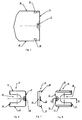
- the device according to the invention shown in the drawing serves the rapid and secure and simple fastening of a pipe leading to a burner on a pipe Outlet opening of a gas valve.
- the device according to the invention accordingly ensures a quick coupling between the pipe leading to the burner and the gas valve.
- FIG. 1 shows a pipe 10 leading to a burner (not shown), which into a Outlet opening 11 of a gas valve 12 shown only schematically and partially is introduced, the outlet opening 11 being bordered by an end face 13.
- a clip element 14 With the device according to the invention, which is shown in FIG. 1 as a clip element 14, the position of the tube 10 is secured in the outlet opening 11 of the gas valve 12.
- the base element 15 has as Clip element 14 designed device according to the invention over a in one plane extending base element 15.
- the base element 15 On two opposite first sides 16, 17 the base element 15 each has a U-shaped web 18, 19 Crosspieces 18, 19 are by correspondingly folding the sides 16, 17 of the base element 15 educated.
- the base element 15 also has a recess 20.
- the recess 20 is open on a second side 20 running perpendicular to the first sides 16, 17.
- the recess 20 accordingly has a U-shaped shape.
- the Base element 15 has a barb-like anchoring element 23. Also in the area of the third side 22, the base element 15 has a grip part 24 Handle part 24 is also formed by folding the base element 15.
- the barb-like anchoring element 23 has an approximately U-shaped shape trained punch cut 25 introduced into the base member 15. Furthermore, that is Anchoring element bent out of the plane of the base element 15, namely in the same direction as the webs 18, 19 and opposite to the direction like that Handle part 24. This can be seen in particular from FIGS. 9, 10.
- the clips 26, 27 have a to the webs 18, 19th corresponding shape and are in perpendicular to the end face 13 Side walls 28, 29 of the gas valve 12 are introduced.
- the guides 26, 27 can in particular Figures 1, 3 and 5 can be seen.
- the recess 20 is in fact dimensioned so that they secure the position - and thus for fastening - of the tube 10 on the gas valve 12 on the one hand includes the tube 10 and on the other hand a radial extending bead 30 of the tube 10 covers. In the case in the outlet opening 11 introduced tube 10, the bead 30 closes flush with the end face 13 of the gas valve 12 from. This can be seen in particular in FIG. 2.
- the clip element 14 completely inserted with its webs 18, 19 into the guides 26, 27, so covered the base element 15 the bead 30 and thus secures the position of the tube 10 in the Exit opening 11.
- the pipe 10 can then no longer exit the exit opening 11 be moved out.
- the tube 10 is accordingly simple and can be fastened in and fastened in the outlet opening 11 of the gas valve 12 secure this position.
- the guides 26, 27 ensure in connection with the Web 18, 19 of the device according to the invention the safe and quick insertion of the clip element 14.
- the anchoring element 23 secures its position in Mounting position. This can only be done with the help of a tool Anchoring element 23 is moved out of the corresponding recess 31 or 32 and thus the clip element 14 are moved out of its fastening position.
- the device according to the invention accordingly ensures the fastening of the tube 10 on the gas valve 12 within a very short time. Also the length of the tube 10 and thus the distance between the burner, not shown, and the gas valve 12 is very short being held.
- the clip element 14 is preferably made of thin spring plate.
Landscapes
- Engineering & Computer Science (AREA)
- Chemical & Material Sciences (AREA)
- Combustion & Propulsion (AREA)
- Mechanical Engineering (AREA)
- General Engineering & Computer Science (AREA)
- Feeding And Controlling Fuel (AREA)
- Valve Housings (AREA)
Abstract
Description
- Fig. 1
- eine erfindungsgemäße Vorrichtung zusammen mit einem an einer Austrittsöffnung eines Gasventils befestigten Rohr in einer Explosionsdarstellung;
- Fig. 2
- ein mit der erfindungsgemäßen Vorrichtung an einer Austrittsöffnung befestigtes Rohr in einer Schnittdarstellung;
- Fig. 3
- ein mit der erfindungsgemäßen Vorrichtung an einer Austrittsöffnung befestigtes Rohr in einer gegenüber der Darstellung gemäß Fig. 2 um 90° gedrehten Schnittdarstellung;
- Fig. 4
- die Austrittsöffnung des Gasventils in Vorderansicht;
- Fig. 5
- die Austrittsöffnung des Gasventils in teilweiser Seitenansicht,
- Fig. 6
- die erfindungsgemäße Vorrichtung in Draufsicht;
- Fig. 7
- die erfindungsgemäße Vorrichtung in Seitenansicht;
- Fig. 8
- die erfindungsgemäße Vorrichtung in Unteransicht;
- Fig. 9
- einen Schnitt durch die erfindungsgemäße Vorrichtung entlang der Schnittlinie IX-IX in Fig. 8; und
- Fig. 10
- einen teilweisen Schnitt durch die erfindungsgemäße Vorrichtung gemäß dem Detail X in Fig.9.
- 10
- Rohr
- 11
- Austrittsöffnung
- 12
- Gasventil
- 13
- Stirnseite
- 14
- Klippelement
- 15
- Grundelement
- 16
- Seite
- 17
- Seite
- 18
- Steg
- 19
- Steg
- 20
- Ausnehmung
- 21
- Seite
- 22
- Seite
- 23
- Verankerungselement
- 24
- Griffteil
- 25
- Stanzschnitt
- 26
- Führung
- 27
- Führung
- 28
- Seitenwandung
- 29
- Seitenwandung
- 30
- Wulst
- 31
- Ausnehmung
- 32
- Ausnehmung
- 33
- Absatz
Claims (4)
- Vorrichtung zur Befestigung eines Rohrs (10) an einer Austrittsöffnung (11) eines Gasventils (12) mit einem im wesentlichen eben ausgebildeten Grundelement (15), dadurch gekennzeichnet, daß:a) das Grundelement (15) an zwei einander gegenüberliegenden ersten Seiten (16,17) jeweils einen u-förmig ausgebildeten Steg (18,19) aufweist, wobei die Stege (18,19) in entsprechende Führungen (26,27) am Gasventils (12) einbringbar sind,b) das Grundelement (15) eine Ausnehmung (20) aufweist, die an einer senkrecht zu den ersten Seiten (16,17) verlaufenden zweiten Seite (21) offen ist,c) das Grundelement (15) im Bereich einer der zweiten Seite (21) gegenüberliegenden dritten Seite (22) ein widerhakenartiges Verankerungselement (23) aufweist, wobei das Verankerungselement (23) in eine entsprechende Ausnehmung (31,32) am Gasventils einbringbar ist.
- Vorrichtung nach Anspruch 1, dadurch gekennzeichnet, daß die Ausnehmung (20) derart bemessen ist, daß sie zur Befestigung des Rohrs (10) am Gasventils (12) einerseits das Rohr (10) umfaßt und andererseits einen sich radial erstreckenden Wulst (30) des Rohrs (10) überdeckt.
- Vorrichtung nach Anspruch 1 oder 2, dadurch gekennzeichnet, daß das widerhakenartige Verankerungselement (23) durch einen u-förmig ausgebildeten Stanzschnitt (25) in das Grundelement (15) eingebracht ist.
- Vorrichtung nach einem oder mehreren der Ansprüche 1 bis 3, dadurch gekennzeichnet, daß widerhakenartige Verankerungselement (23) durch Einbringen eines Werkzeugs, insbesondere eines Schraubenziehers, in die dem Gasventil (12) zugeordnete Ausnehmung (31,32) aus der Ausnehmung (31,32) herauslösbar ist.
Applications Claiming Priority (2)
| Application Number | Priority Date | Filing Date | Title |
|---|---|---|---|
| DE29821843U | 1998-12-08 | ||
| DE29821843U DE29821843U1 (de) | 1998-12-08 | 1998-12-08 | Vorrichtung zur Befestigung eines Rohrs an einer Austrittsöffnung eines Gasventils |
Publications (2)
| Publication Number | Publication Date |
|---|---|
| EP1008804A2 true EP1008804A2 (de) | 2000-06-14 |
| EP1008804A3 EP1008804A3 (de) | 2000-07-26 |
Family
ID=8066335
Family Applications (1)
| Application Number | Title | Priority Date | Filing Date |
|---|---|---|---|
| EP99123882A Withdrawn EP1008804A3 (de) | 1998-12-08 | 1999-12-02 | Vorrichtung zur Befestigung eines Rohrs an einer Austrittsöffnung eines Gasventils |
Country Status (2)
| Country | Link |
|---|---|
| EP (1) | EP1008804A3 (de) |
| DE (1) | DE29821843U1 (de) |
Cited By (1)
| Publication number | Priority date | Publication date | Assignee | Title |
|---|---|---|---|---|
| EP3896321A1 (de) | 2020-04-14 | 2021-10-20 | Pittway Sarl | Montageclip zur befestigung einer betätigungseinheit an einer ventileinheit und anordnung mit einer betätigungseinheit, ventileinheit und montageclip |
Citations (1)
| Publication number | Priority date | Publication date | Assignee | Title |
|---|---|---|---|---|
| DE4332199A1 (de) * | 1993-09-22 | 1995-03-23 | Freudenberg Carl Fa | Steckverbindung |
Family Cites Families (7)
| Publication number | Priority date | Publication date | Assignee | Title |
|---|---|---|---|---|
| US3560027A (en) * | 1967-02-20 | 1971-02-02 | Gra Tec Inc | Coupling assembly |
| DE8718030U1 (de) | 1987-12-08 | 1992-12-24 | Paul Isphording Metallwerke GmbH & Co KG, 5952 Attendorn | Brennerrohr |
| DE3817472A1 (de) * | 1988-05-21 | 1989-11-30 | Daimler Benz Ag | Verriegelung fuer eine fluidische steckverbindung |
| US5092300A (en) * | 1991-01-31 | 1992-03-03 | Siemens Automotive L.P. | Plastic fuel rail end joint |
| WO1993014341A1 (en) * | 1992-01-17 | 1993-07-22 | Huron Products Industries Inc. | Tubing connector |
| AT403953B (de) | 1996-04-09 | 1998-07-27 | Vaillant Gmbh | Rohrverbindung |
| WO1999004161A1 (en) * | 1997-07-16 | 1999-01-28 | Siemens Canada Limited | Device for mounting a pressure regulator on a plastic fuel line |
-
1998
- 1998-12-08 DE DE29821843U patent/DE29821843U1/de not_active Expired - Lifetime
-
1999
- 1999-12-02 EP EP99123882A patent/EP1008804A3/de not_active Withdrawn
Patent Citations (1)
| Publication number | Priority date | Publication date | Assignee | Title |
|---|---|---|---|---|
| DE4332199A1 (de) * | 1993-09-22 | 1995-03-23 | Freudenberg Carl Fa | Steckverbindung |
Cited By (4)
| Publication number | Priority date | Publication date | Assignee | Title |
|---|---|---|---|---|
| EP3896321A1 (de) | 2020-04-14 | 2021-10-20 | Pittway Sarl | Montageclip zur befestigung einer betätigungseinheit an einer ventileinheit und anordnung mit einer betätigungseinheit, ventileinheit und montageclip |
| WO2021209359A1 (en) | 2020-04-14 | 2021-10-21 | Pittway Sarl | Mounting clip to mount an actuator unit to a valve unit and assembly having an actuator unit, a valve unit and a mounting clip |
| EP4234953A2 (de) | 2020-04-14 | 2023-08-30 | Pittway Sarl | Anordnung mit einer betätigungseinheit, ventileinheit und montageclip |
| US12203497B2 (en) | 2020-04-14 | 2025-01-21 | Pittway Sarl | Mounting clip to mount an actuator unit to a valve unit and assembly having an actuator unit, a valve unit and a mounting clip |
Also Published As
| Publication number | Publication date |
|---|---|
| EP1008804A3 (de) | 2000-07-26 |
| DE29821843U1 (de) | 1999-02-18 |
Similar Documents
| Publication | Publication Date | Title |
|---|---|---|
| EP1947750B1 (de) | Befestigungsvorrichtung für Kabel | |
| EP1541878B1 (de) | Befestigungssystem | |
| DE102014015679A1 (de) | Kippdübel und Verfahren zur Montage eines Kippdübels | |
| DE10054334A1 (de) | Haltefeder zur lösbaren Verbindung von zwei Bauteilen | |
| DE4125072C2 (de) | Befestigungsklammer für Rohre, Schläuche, Kabel und Rohrleitungen | |
| EP0404726A2 (de) | Vorrichtung zum Verbinden von C-förmigen Schienen, insbesondere Montageschienen | |
| WO1998007994A1 (de) | Verbindung zwischen zwei bauteilen | |
| EP1375993B1 (de) | Kupplungsmuffe für gewellt ausgebildete Rohre | |
| EP0694658A1 (de) | Befestigungsvorrichtung für Dachziegel | |
| DE29509360U1 (de) | Vorrichtung zum Befestigen eines mit einem plattenförmigen Teil versehenen Elementes an einer Wand in einem Gehäuse o.dgl. | |
| DE29500353U1 (de) | Vorrichtung zur höhenverstellbaren kraftschlüssigen Befestigung, insbesondere zum Abhängen von Holzunterkonstruktionen für Decken | |
| DE4138047C2 (de) | Vorrichtung zum Verbinden mehrerer Teile | |
| DE20108187U1 (de) | Universalverbinder | |
| DE29821843U1 (de) | Vorrichtung zur Befestigung eines Rohrs an einer Austrittsöffnung eines Gasventils | |
| DE3038957C2 (de) | Anbaugehäuse zur Befestigung eines in einem Gehäuse angeordneten Geräts | |
| DE10216453B4 (de) | Schraubenlose Befestigungseinrichtung | |
| DE3941097C1 (en) | Cable channel or tray support - has coupling element fixable from above in form of shaft fitting selectable slots and with projection to act like hook | |
| EP1459938B1 (de) | Befestigungsvorrichtung zur lösbaren Festlegung eines Bauteils an einem Trägerteil | |
| EP4181734B1 (de) | Adaptereinheit zur verbindung eines schubkastenbodens mit einer seitenzarge eines schubkastens, seitenzarge und schubkasten | |
| DE2539747C3 (de) | Leitungshalter | |
| DE3150904C2 (de) | ||
| DE3819367A1 (de) | Vorrichtung zum befestigen von installationsmaterial | |
| DE202017107262U1 (de) | Amboss eines Heftgeräts | |
| DE19544069C2 (de) | Haltevorrichtung für eine Steckkarte | |
| DE102023114097A1 (de) | Drahthalter zum Befestigen eines Drahtes an einem Bauteil sowie Verwendung eines Drahthalters |
Legal Events
| Date | Code | Title | Description |
|---|---|---|---|
| PUAI | Public reference made under article 153(3) epc to a published international application that has entered the european phase |
Free format text: ORIGINAL CODE: 0009012 |
|
| PUAL | Search report despatched |
Free format text: ORIGINAL CODE: 0009013 |
|
| AK | Designated contracting states |
Kind code of ref document: A2 Designated state(s): AT BE CH CY DE DK ES FI FR GB GR IE IT LI LU MC NL PT SE |
|
| AX | Request for extension of the european patent |
Free format text: AL;LT;LV;MK;RO;SI |
|
| AK | Designated contracting states |
Kind code of ref document: A3 Designated state(s): AT BE CH CY DE DK ES FI FR GB GR IE IT LI LU MC NL PT SE |
|
| AX | Request for extension of the european patent |
Free format text: AL;LT;LV;MK;RO;SI |
|
| RIC1 | Information provided on ipc code assigned before grant |
Free format text: 7F 23D 14/46 A, 7F 16L 37/14 B |
|
| 17P | Request for examination filed |
Effective date: 20000620 |
|
| AKX | Designation fees paid |
Free format text: AT BE CH CY DE DK ES FI FR GB GR IE IT LI LU MC NL PT SE |
|
| 17Q | First examination report despatched |
Effective date: 20020325 |
|
| STAA | Information on the status of an ep patent application or granted ep patent |
Free format text: STATUS: THE APPLICATION IS DEEMED TO BE WITHDRAWN |
|
| 18D | Application deemed to be withdrawn |
Effective date: 20020806 |