EP1007952B1 - Differenz-thermoanalyse-vorrichtung - Google Patents
Differenz-thermoanalyse-vorrichtung Download PDFInfo
- Publication number
- EP1007952B1 EP1007952B1 EP19980945284 EP98945284A EP1007952B1 EP 1007952 B1 EP1007952 B1 EP 1007952B1 EP 19980945284 EP19980945284 EP 19980945284 EP 98945284 A EP98945284 A EP 98945284A EP 1007952 B1 EP1007952 B1 EP 1007952B1
- Authority
- EP
- European Patent Office
- Prior art keywords
- coupling
- sensor plate
- reference sample
- test sample
- sample
- Prior art date
- Legal status (The legal status is an assumption and is not a legal conclusion. Google has not performed a legal analysis and makes no representation as to the accuracy of the status listed.)
- Expired - Lifetime
Links
Images


Classifications
-
- G—PHYSICS
- G01—MEASURING; TESTING
- G01N—INVESTIGATING OR ANALYSING MATERIALS BY DETERMINING THEIR CHEMICAL OR PHYSICAL PROPERTIES
- G01N25/00—Investigating or analyzing materials by the use of thermal means
- G01N25/20—Investigating or analyzing materials by the use of thermal means by investigating the development of heat, i.e. calorimetry, e.g. by measuring specific heat, by measuring thermal conductivity
- G01N25/48—Investigating or analyzing materials by the use of thermal means by investigating the development of heat, i.e. calorimetry, e.g. by measuring specific heat, by measuring thermal conductivity on solution, sorption, or a chemical reaction not involving combustion or catalytic oxidation
- G01N25/4806—Details not adapted to a particular type of sample
- G01N25/4813—Details not adapted to a particular type of sample concerning the measuring means
- G01N25/482—Details not adapted to a particular type of sample concerning the measuring means concerning the temperature responsive elements
Definitions
- the invention relates to a differential thermal analysis device for metrological Examination or determination of a thermophysical parameter a measurement sample, especially for examining phase transitions or to determine the specific heat of the measurement sample.
- DTA devices Differential thermal analysis devices
- DSC heat flow difference calorimeter
- US-A-4 095 453 Another known differential thermal analysis device is in US-A-4 095 453.
- This device is provided with a heat source, a sensor plate with a test sample coupling zone for a test sample and a reference sample docking zone for a reference sample, one Measurement sample temperature sensor, a reference sample temperature sensor and an evaluation unit.
- the known device also has a sensor plate on, which in some areas consists of ceramic material. This ceramic Sensor plate fulfills a purely constructive within the known device Function as a mechanical carrier element and does not contribute to the generation of electrical signals at.
- test sample and a reference sample is simultaneously subjected to a predetermined temperature profile. If there is a phase change in the sample or there is a difference in the specific heat between sample and reference, this is reflected in a temperature difference between the sample and the reference substance is noticeable.
- This temperature difference is suitable for the sample and reference substance attached thermocouples detected and converted into an electrical voltage.
- This measuring method has been established for decades and is used by both low temperatures down to the milli-Kelvin range as well as high ones Temperatures up to over 2000 ° C used.
- thermocouple materials used only possible, only one of these parameters at the expense of the other towards greater efficiency to increase the measuring system.
- a high resolution z. B. achieved in that not a single Thermocouple was used for temperature measurement, but a thermopile integrated into the sample pan has been.
- the resulting increase in sensitivity of such a so-called cup system however with an increase in the time constant hand in hand, because the design in the shape of a mug the effective thermal mass of the measuring head is increased.
- Fast conventional measuring arrangements contain one single sensor plate made of a metallic thermocouple material such as B. Chromel, Constantan or Platinum, at two places thermocouple wires are attached. The are in these positions two crucibles with the test sample and comparison or Reference sample. Such a system is also called a disc measuring system designated. Because the plate at the crucible positions and in their immediate vicinity if possible This area is very thin small thermal mass and the arrangement reached thus a small time constant. However, it is System because of the low thermal stresses of the metallic Thermocouple materials relatively insensitive.
- the task of a differential thermal analysis system is it, a temperature difference between a sample and a Comparative substance with a dynamic temperature curve to be measured in such a way that it is as quantitative as possible Conclusions about conversion energies or the specific one Heat become possible.
- the measurement of the temperature difference can depend on the type and task done differently. Is it z. B. on the Detection of an extremely low conversion heat, So far, preferably a cup system with a thermopile used. This results because of the big one Time constants in the temperature difference over time Representation in a flat signal, which is slow subsides. Must have several on the temperature scale nearby conversions resolved the case may arise that the time resolution not because of the large time constants sufficient.
- the invention has for its object a differential thermal analysis device to create that at low time constants a maximum sensitivity temperature resolution guaranteed.
- a heat source feeds a sensor plate that is thermally coupled to the heat source.
- On the Sensor plate are at least one coupling zone thermal coupling of the test sample to be measured and at least one coupling zone for thermal coupling of the reference sample.
- temperature sensors for determining the local temperatures within the coupling zones. at these temperature sensors are in particular thermocouples that correspond to temperature give off electrical voltage.
- the temperature sensors are connected to an evaluation unit. Based on measured temperature difference and the known behavior the reference sample can be determined using the output signal the evaluation unit to the behavior of the close the test sample to be examined.
- the temperature sensors are preferably each as Thermocouples formed from the combination of materials Sensor plate and one supply line each (Thermal cable) exist.
- thermoelectric Semiconductor material used in ceramic or single or polycrystalline form.
- thermoelectric properties show namely same or even reduced time constants in a temperature range, albeit a limited one increased sensitivity since it is in this Temperature range significantly higher Seebeck coefficients exhibit.
- the limited temperature range results from the fact that associated with the for Semiconductor typical temperature profile of the conductance the Seebeck coefficient (often as "Thermo power") in the area of its highest Forms a characteristic maximum.
- the high sensitivity of the differential thermal analysis device according to the invention is through special semiconductor physical effects of at least semiconductor material used for the coupling zones causes these effects inseparable from the specific Temperature characteristic of the Seebeck coefficient are connected.
- the Seebeck coefficient rises predominantly with the temperature steadily before it is inserted the intrinsic line decreases again and to very little Values falling.
- a limited temperature interval of a maximum of a few 100 K Advantage of an extremely high sensitivity with the invention Differential thermal analysis device be exploited.
- the differential thermal analysis device should be able to be used in practice over a wide temperature range an essentially uniformly high one Sensitivity (and temperature resolution), so one have uniformly large thermal voltage. by virtue of of the current state of knowledge one is always away from it assumed that this requirement only from metallic Sensor plates can be satisfied. These systems show low values of the Seebeck coefficient which, however, rise to high temperatures or stabilize at medium values. moreover the well-known metallic sensors are good structured by the high charge carrier densities of the Metals insensitive to contamination as well phase stable. The latter is particularly for such sensitive measuring system, such as differential thermal analysis represents, of importance.
- thermoelectric Semiconductor materials for or in the sensor plate (active element or sensor element)
- one Differential thermal analysis device can be also thermal analysis systems with high sensitivity Realize over a wide temperature range.
- the characteristic temperature namely, the drop in the Seebeck coefficient of semiconducting materials is used by the doping concentration and the width of the band gap determined in the semiconductor.
- the band gap is one material-specific parameters and varies by material to material. For most standard semiconductors can the doping concentration over several powers of ten defined. So that can Onset of self-management and thus the maximum of Seebeck coefficients are practical for a given one Temperature can be "programmed".
- By combining only two or three specially matched semiconductor materials can be used for practical measuring systems relevant temperature range are already covered.
- Each measurement sample or reference sample is therefore included thermally coupled with a single coupling zone. All coupling zones are with temperature sensors, in particular provided thermocouples, their output voltages are fed to the evaluation unit. The evaluation unit now selects that for the difference measurement Coupling zone pair, their associated temperature sensors provides the greatest output voltages.
- the sensor plate construction described above does it required that several identical samples be taken simultaneously be measured or examined. This can ever be problematic after the test, if the amount of substance to be examined is limited. For such a case, there are different ones Semiconductor materials in a common Focus docking zone, being this individual Coupling subzones so close to each other are arranged so that they are all in thermal at the same time Contact with a test sample or a reference sample stand. Also in this configuration of the sensor plate applies that the individual coupling sub-zones are centrally symmetrical are arranged. As a geometric shape a coupling zone offers, for example Circular area. In the configuration described above the sensor plate with per measurement sample or reference sample coupling zone to this extent it is in several sub-zones expedient to use integer partial areas of the circular area to prove different semiconductor materials, the individual subareas electrically against each other are isolated.
- An increase in thermal resistance around the coupling zones around can be realized constructively by that the amount of material in the area between the docking zones and the rest of the sensor plate becomes. This in turn can be done by reducing the Thickness of the sensor plate in the connection area between the coupling zones and the main mass of the sensor plate and / or by making recesses in them Connection area can be realized.
- the cutouts can be done by an etching technique, by laser cutting, mechanical grinding or the like known per se Material processing techniques can be realized.
- a metal coating to the coupling zones.
- Ni, Au, Mo, Pt, Al or alloys thereof are particularly suitable for this, the thickness of the metal coating generally being between 0.1 and 500 ⁇ m.
- a protective layer between the semiconducting material and the metal coating, which is preferably an oxide.
- a non-conductive, chemically inert coating in particular SiO 2 , SiN, Al 2 O 3 .
- thermoelectric semiconducting ceramic or single or polycrystalline Semiconductor material as an active material provided sensor plate there are various solution concepts on.
- the Sensor plate made of metal or another basic material with good thermal conductivity, being in the Plate for each coupling zone to be created or a piece of semiconducting thermoelectric Material inserted, welded, soldered or in is otherwise fixed.
- the at least two coupling zones are electrically connected to one another connected so that the required by the thermocouples Temperature difference measurement using of the Seebeck effect can take place.
- the above structure lends itself to the sensor plate from insulating or electrically poorly conductive Material (e.g.
- the sensor plate one or more layers or Conductor tracks made of ceramic or crystalline thermoelectric Semiconductors that support the coupling zones form and electrically connect with each other.
- the sensor plate electrically insulating or poorly conductive material to produce with good thermal conductivity, the electrical contacts between the highly sensitive Coupling zones in the above manner on or in the sensor plate are arranged by an applied metallization or other types of metallic connections will be produced.
- the currently largest market for thermal analysis devices is quality control in material manufacturing and manufacturing industry.
- the To name polymer range where polymerization behavior is tested in temperature ranges up to 400 ° C.
- the achievable sensitivities today's disc measurement systems are here sufficient. Nevertheless, an improvement can be made by the Differential thermal analysis device according to the invention can be achieved because the increased sensitivity enables higher heating rate and thus the cycle time for the entire measurement is shortened.
- Fig. 1 is a first embodiment of a differential thermal analysis device 10 shown in principle.
- This device 10 has a heat source 12 on whose heat is via a thermally coupled rod 14 or an outer casing, capsule or the like disc-shaped sensor plate 16 is supplied.
- the Sensor plate 16 is thermal with rod 14 coupled, the rod 14 at the center of the sensor plate 16 or connected to it at its extent is.
- a coupling zone 18 is on the sensor plate 16 for a measurement sample 20 and a coupling zone 22 for a Reference sample 24 formed. These two coupling zones 18,22 are diametrically opposed to each other and thus centrally symmetrical to the center of the Sensor plate 16 arranged.
- the measurement sample 20 and Reference sample 24 are housed in crucibles 26, 28 in good thermal contact on the Coupling zones 18, 22 are available.
- the sensor plate 16 is made consistently of a ceramic, single or polycrystalline thermoelectric semiconducting material, which is in particular one of the Introduction to the materials mentioned.
- On the underside of the sensor plate 16 in the area of the Coupling zones 18, 22 are thermocouples 30, 32, by connecting electrical leads 34,36 are realized with the sensor plate 16.
- the material this leads 34, 36 is different from that Material of the sensor plate 16.
- the usual metallic leads 34,36 Thermocouple materials for use.
- the supply lines 34, 36 lead to an evaluation unit 38 in which the due to the temperatures of the coupling zones 18, 22 adjusting voltage difference between the two Feed lines 34,36 is evaluated.
- the result will be displayed on a display device 40 stored in a control computer.
- the sensor plate 16 has metallizations in the area of its coupling zones 18, 22, which serve to improve the heat transfer from the sensor plate 16 to the crucibles 26, 28. Between these metallization coatings 42, 44 and the sensor plate 16, a (for example, electrically insulating) protective layer made of, in particular, an oxide can be arranged in order to suppress interference signals due to phase conversions. In the remaining area outside the coupling zones 18, 22, the sensor plate is provided with a protective layer 46 made of, for example, SiO 2 , SiN, Al 2 O 3 .
- the Sensor plate 16 heated by the heat source 12. there the heat flow from the heat source 12 over the Rod 14 to the center of the sensor plate 16, from where it is discharged evenly radially outwards. to It is advisable to carry out quick measurements when the thermal resistance is low. on the other hand should prevent heat flow from the Coupling zones 18, 22 to the remaining area of the sensor plate 16 ensure that the thermal resistance around the coupling zones 18, 22 is enlarged.
- Coupling zones 18 and 22 differ in strength heat. This temperature difference is over the Differential thermocouple (DTE) 34, 16, 36 detected and in a measuring voltage is converted in the evaluation unit 38 is evaluated.
- DTE Differential thermocouple
- Fig. 2 shows a top view of an alternative embodiment the sensor plate 16 of FIG. 1.
- this sensor plate In FIG. 2 designated this sensor plate with 16 '. So much for the parts of the sensor plate 16 'that of the sensor plate 16 Fig. 1 correspond, they are the same in Fig. 2 Provide reference numerals.
- the alternative configuration of the sensor plate 16 ' is to increase the thermal resistance around the coupling zones 18, 22 around a specially designed one Connection area 48 created in the in the sensor plate 16 'with several continuous recesses 50 interposed radially extending webs 52 introduced are. So are over the connecting webs 52 the coupling zones 18, 22 mechanically and electrically with connected to the rest of the sensor plate 16 '.
- the connecting bars 52 also have a smaller thickness than that Sensor plate 16 'in its remaining area. This Spoke-like construction leads to an increased Thermal resistance around the coupling zones 18, 22 what the measurement sensitivity of the sensor plate 16 'increases.
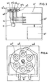
- FIG. 3 shows a basic illustration of a differential thermal analysis device 10 "according to another Embodiment of the invention.
- the sensor plate 16 "of the thermal analysis device 10 has a total of three coupling zones 18a", 18b “ and 18c “for three test samples and three coupling zones 22a “, 22b” and 22c "for three reference samples Measurement samples and the reference samples must each be among themselves be identical.
- thermocouples 30a "-30c" and 32a are assigned "-32c”. These are thermocouples in pairs with the evaluation unit 38 ".
- FIGS. 5 and 6 Another embodiment of a sensor plate 16 '' 'with several different thermoelectric semiconducting materials is shown in FIGS. 5 and 6. The same applies here that those parts of the sensor plate 16 '' ', those parts of the sensor plate 16 1 correspond, with the same reference numerals, but are marked with three lines.
- the sensor plate 16 also has 16 '' 'several test sample coupling zones 18a' '' - 18d '' ' and several reference sample coupling zones 22a '' '- 22d' '' on, which are center symmetrical to the center in pairs the sensor plate 16 '' 'are arranged.
- the sensor plate 16 " is the sensor plate 16 '' 'but only one sample and one Reference sample position provided. In other words contacts (thermally) a crucible for the test sample all four test sample coupling zones 18a '' '- 18d' '', during the crucible for the reference sample all reference sample coupling zones 22a '' '- 22d' '' contacted.
- each The coupling zone is again with a thermocouple 30a '' '- 30d' '' and 32a '' '- 32d' '', their supply lines are supplied in pairs to the evaluation unit. Since the measurement sample and reference sample coupling zones in pairs from identical semiconductor material and from Pair to pair made of different semiconductor materials exist, stand at the coupling zones each associated with a pair of thermocouples different voltage differences U1-U4. The Evaluation unit chooses the largest for evaluation purposes of the voltage differences. This ensures that across the entire interested Temperature range each with a maximum of large Voltage differences can be worked, what about this leads that the sensor plate 16 '' 'over the entire interesting temperature range across a large Has sensitivity.
- Figs. 5 and 6 are the sample coupling zones and the reference sample docking zones thanks to electrically insulating, highly heat-conductive ceramic disks 56 (generally disc made of electrically insulating, thermally well coupled to the coupling zones Material) connected, each in the middle of the Coupling zones are arranged. On these ceramic discs 56 are the crucibles for the measurement sample and the reference sample posed.
- the sensor plate 16 '' ' is particularly suitable if the same semiconductor base material for the coupling zones, however with different endowments is used. Because of the proximity of the arrangement of the coupling zones it is useful if this show the same temperature expansion behavior. This is most guaranteed if the basic materials are the same and differ only slightly due to the doping differ. In this way, too Requirement that it is due to the heating of the sensor plate 16 '' 'not to destroy them due to thermal Tensions may come, enough is done.
Landscapes
- Chemical & Material Sciences (AREA)
- Engineering & Computer Science (AREA)
- Chemical Kinetics & Catalysis (AREA)
- Combustion & Propulsion (AREA)
- Physics & Mathematics (AREA)
- Health & Medical Sciences (AREA)
- Life Sciences & Earth Sciences (AREA)
- Analytical Chemistry (AREA)
- Biochemistry (AREA)
- General Health & Medical Sciences (AREA)
- General Physics & Mathematics (AREA)
- Immunology (AREA)
- Pathology (AREA)
- Investigating Or Analyzing Materials Using Thermal Means (AREA)
Description
- die Empfindlichkeit der Temperatur-Auflösung ξ und
- die Zeitkonstante der Anordnung τ
- einer Wärmequelle,
- einer thermisch mit der Wärmequelle gekoppelten Sensorplatte, auf bzw. in der eine Meßproben-Ankoppelzone zur thermischen Ankopplung einer zu vermessenden Meßprobe und eine Referenzproben-Ankoppelzone zur thermischen Ankopplung einer Referenzprobe mit einem bezüglich des zu untersuchenden oder zu messenden Parameters bekannten Verhalten ausgebildet sind,
- einem Meßproben-Temperatursensor zur Ermittlung der lokalen Temperatur der Sensorplatte an der Meßproben-Meßstelle,
- einem Referenzproben-Temperatursensor zur Ermittlung der lokalen Temperatur der Sensorplatte an der Referenzproben-Meßstelle und
- einer Auswerteeinheit, die mit den Temperatursensoren elektrisch verbunden ist und anhand einer Differenz der lokalen Temperaturen der Meßprobenund Referenzproben-Ankoppelzonen der Sensorplatte sowie des bekannten Verhaltens der Referenzprobe eine Ausgabe erzeugt, die für den interessierenden Parameter der Meßprobe repräsentativ ist,
- wobei die Sensorplatte zumindest innerhalb ihrer Meßproben- und Referenzproben-Ankoppelzonen ein keramisches oder ein ein- oder polykristallines thermoelektrisches Halbleitermaterial aufweist.
- Si1-xGex mit x zwischen 0 und 1 (einschließlich), dotiert mit P, Ga, As oder B oder anderen Zusätzen, insbesondere mit Ladungsträgerdichten zwischen 1015 und 1021 cm-3,
- FeSi2 dotiert mit Co, Al, Mn, Ni oder Cr, ihren Kombinationen oder weiteren Elementen, so daß die Ladungsträgerdichte Werte zwischen 1015 und 1021 cm-3 annimmt,
- Bi2(Te1-xSex)3 mit x zwischen 0 und 1 (einschließlich), so dotiert (z. B. mit J, Cl, Sn, o. dgl. oder mittels Te- oder Se-Überschuß), daß die Ladungsträgerdichte Werte zwischen 1015 und 1021 cm-3 annimmt,
- (Bi1-xSbx)2Te3 mit x zwischen 0 und 1 (einschließlich), so dotiert (z. B. mit Pb, Ge, o. dgl. oder mittels Bi- oder Sb-Überschuß), daß die Ladungsträgerdichte Werte zwischen 1015 und 1021 cm-3 annimmt, und
- Halbleiter, die durch geeignete Dotierungen Störbandleitungseffekte ("hopping conductivity") oder Polaronen-Effekte zeigen, und die daher in der Lage sind, die Thermospannung über breite Temperaturbereiche hinweg zu erhöhen. Hier sind insbesondere die Materialien AlB12, FeSi2 und B1-xCx zu nennen.
- Fig. 1
- eine schematische Darstellung des Aufbaus einer Differenz-Thermoanalyse-Vorrichtung unter Verwendung einer Sensorplatte gemäß einem ersten Ausführungsbeispiel der Erfindung,
- Fig. 2
- eine Draufsicht auf eine Sensorplatte gemäß einem zweiten Ausführungsbeispiel der Erfindung mit auf konstruktive Weise realisierter Wärmewiderstandskonzentration um die Meßproben- und Referenzproben-Positionen,
- Fig. 3
- eine prinzipielle Darstellung einer Differenz-Thermoanalyse-Vorrichtung gemäß einem weiteren Ausführungsbeispiel der Erfindung, bei dem die Sensorplatte mehrere Referenzproben- und Meßproben-Positionen mit unterschiedlichen halbleitenden Materialien aufweist.
- Fig. 4
- eine Draufsicht auf die Sensorplatte der Vorrichtung gemäß Fig. 3,
- Fig. 5
- eine Draufsicht von oben auf die Sensorplatte einer weiteren Differenz-Thermoanalyse-Vorrichtung und
- Fig. 6
- eine Unteransicht der Sensorplatte gemäß Fig. 5.
Claims (19)
- Differenz-Thermoanalyse-Vorrichtung zur messtechnischen Untersuchung oder Ermittlung eines Parameters einer Messprobe, insbesondere des Phasenübergangs oder der spezifischen Wärme der Messprobe, mitdadurch gekennzeichnet,einer Wärmequelle (12),einer thermisch mit der Wärmequelle (12) gekoppelten Sensorplatte (16,16',16",16'''), auf bzw. in der eine Messproben-Ankoppelzone (18,18',18",18"') zur thermischen Ankopplung einer zu vermessenden Messprobe (20) und eine Referenzproben-Ankoppelzone (22,22',22",22''') zur thermischen Ankopplung einer Referenzprobe (24) mit einem bezüglich des zu untersuchenden oder zu messenden Parameters bekannten Verhalten ausgebildet sind,einem Messproben-Temperatursensor (30,30',30", 30''') zur Ermittlung der lokalen Temperatur der Sensorplatte (16,16',16",16''') an der Messproben-Messstelle,einem Referenzproben-Temperatursensor (32,32',32",32''') zur Ermittlung der lokalen Temperatur der Sensorplatte (16, 16',16",16''') an der Referenzproben-Messstelle undeiner Auswerteeinheit (38,38"), die mit den Temperatursensoren (30,32,30',32',30",32", 30"',32"') elektrisch verbunden ist und anhand einer Differenz der lokalen Temperaturen der Messproben- und Referenzproben-Ankoppelzonen (18,22,18',22',18",22",18''',22''') der Sensorplatte (16,16',16",16''') sowie des bekannten Verhaltens der Referenzprobe eine Ausgabe erzeugt, die für den interessierenden Parameter der Messprobe (20) repräsentativ ist,dass die Sensorplatte (16,16',16",16''') zumindest innerhalb ihrer Messproben- und Referenzproben-Ankoppelzonen (18,22,18',22',18", 22",18''',22''') ein keramisches oder ein ein- oder polykristallines thermoelektrisches Halbleitermaterial aufweist.
- Vorrichtung nach Anspruch 1, dadurch gekennzeichnet, daß das thermoelektrische Halbleitermaterial mit P, Ga, As oder B oder weiteren Elementen in einer Ladungsträgerdichte zwischen 1015 und 1021 1/cm3 dotiertes Si1-xGex ist, wobei x zwischen 0 und 1, einschließlich, liegt.
- Vorrichtung nach Anspruch 1, dadurch gekennzeichnet, daß das thermoelektrische Halbleitermaterial mit Co, Al, Mn, Ni oder Cr oder weiteren Elementen oder Kombinationen davon in einer Ladungsträgerdichte zwischen 1015 und 1021 1/cm3 dotiertes FeSi2 ist.
- Vorrichtung nach Anspruch 1, dadurch gekennzeichnet, daß das thermoelektrisch aktive Material ein Halbleitermaterial auf der Basis von Bi2(Te1-xSex)3 mit Fremddotierung, insbesondere Cl, J, oder einem Te- oder Se-Überschuß entsprechend einer Ladungsträgerdichte zwischen 1015 und 1021 1/cm3 ist, wobei x zwischen 0 und 1, einschließlich, liegt.
- Vorrichtung nach Anspruch 1, dadurch gekennzeichnet, daß das thermoelektrisch aktive Material ein Halbleitermaterial auf der Basis von (Bi1-xSbx)2Te3 mit Fremddotierung, insbesondere Pb, Ge, oder einem Bi- oder Sb-Überschuß entsprechend einer Ladungsträgerdichte zwischen 1015 und 1021 1/cm3 ist, wobei x zwischen 0 und 1, einschließlich, liegt.
- Vorrichtung nach Anspruch 1, dadurch gekennzeichnet, daß das thermoelektrische Halbleitermaterial native oder durch Dotierung hervorgerufene Störbandleitungseffekte oder Polaronen-Effekte aufweist und insbesondere aus AlB12, FeSi2 und B1-xCx mit x zwischen 0 und 1, einschließlich, besteht.
- Vorrichtung nach einem der Ansprüche 1 bis 6, dadurch gekennzeichnet, daß die gesamte Sensorplatte (16,16') aus dem thermoelektrischen Halbleitermaterial besteht.
- Vorrichtung nach einem der Ansprüche 1 bis 6, dadurch gekennzeichnet, daß die Sensorplatte (16, 16',16",16''') eine Trägerplatte aufweist, mit der die Meßproben- und Referenzproben-Ankoppelzonen (18,22,18',22',18",22",18''',22''') aus dem thermoelektrischen Halbleitermaterial thermisch verbunden sind.
- Vorrichtung nach einem der Ansprüche 1 bis 8, dadurch gekennzeichnet, daß die Temperatursensoren (30,32,30',32',30",32", 30''',32''') als Thermoelemente ausgebildet sind, die jeweils eine mit den Meßproben- und Referenzproben-Ankoppelzonen (18,22,18',22',18",22",18''',22''') verbundene Zuleitung (34,36) aus einem von dem thermoelektrischen Halbleitermaterial der Ankoppelzonen (18,22, 18',22',18",22",18''',22''') unterschiedlichen Material aufweisen, wobei die Temperaturdifferenz zwischen der Meßproben-Ankoppelzone und der Referenzproben-Ankoppelzone (18,22,18',22',18",22", 18''',22''') als Spannungsdifferenz zwischen den beiden zu den Thermoelementen führenden Zuleitungen (34,36) vorliegt.
- Vorrichtung nach einem der Ansprüche 1 bis 9, dadurch gekennzeichnet, daß die Sensorplatte (16, 16',16",16''') im Umgebungsbereich um die Ankoppelzonen (18,22,18',22',18",22",18''',22''') herum einen erhöhten Wärmewiderstand aufweist.
- Vorrichtung nach Anspruch 10, dadurch gekennzeichnet, daß der erhöhte Wärmewiderstand konstruktiv durch Verringerung der Menge an Material im Umgebungsbereich (48) der Ankoppelzonen (18,22,18', 22',18",22",18''',22''') realisiert ist.
- Vorrichtung nach Anspruch 11, dadurch gekennzeichnet, daß der Umgebungsbereich (48) Aussparungen und/oder Verdünnungen (52) aufweist.
- Vorrichtung nach einem der Ansprüche 1 bis 12, dadurch gekennzeichnet, daß die Sensorplatte (16", 16''') mehrere Paare von Meßproben- und Referenzproben-Ankoppelzonen (18",22",18''',22''') aufweist, wobei jedes Paar aus Halbleitermaterial mit verschiedenen thermoelektrischen Eigenschaften besteht, daß jede Meßproben- und Referenzproben-Ankoppelzone (18",22",18''',22''') einem Temperatursensor (30",32",30''',32''') zugeordnet ist, die sämtlich elektrisch mit der Auswerteeinheit (38") verbunden sind, und daß die Auswerteeinheit (38") die Differenztemperatur anhand der größten Ausgangssignale der einem Paar von Meßproben- und Referenzproben-Ankoppelzonen (18",22",18''',22''') zugeordneten Temperatursensoren (30",32",30''', 32''') ermittelt.
- Vorrichtung nach Anspruch 13, dadurch gekennzeichnet, daß jede Ankoppelzone (18",22") zur thermischen Kopplung mit einer Meß- oder Referenzprobe (20,24) vorgesehen ist.
- Vorrichtung nach Anspruch 13, dadurch gekennzeichnet, daß mehrere, insbesondere sämtliche Meßproben-Ankoppelzonen (18''') und mehrere, insbesondere sämtliche Referenzproben-Ankoppelzonen (22''') gemeinsam zur thermischen Kopplung mit einer Meßprobe (20) bzw. einer Referenzprobe (24) vorgesehen sind.
- Vorrichtung nach einem der Ansprüche 13 bis 15, dadurch gekennzeichnet, daß die Ankoppelzonenpaare (18",22",18''',22''') aus unterschiedlichen Halbleitermaterialien bestehen.
- Vorrichtung nach einem der Ansprüche 13 bis 15, dadurch gekennzeichnet, daß die Ankoppelzonenpaare (18",22",18''',22''') aus dem gleichen Halbleitermaterial bestehen, jedoch unterschiedliche Dotierungen und/oder Dotierungsladungsträgerdichten aufweisen.
- Vorrichtung nach einem der Ansprüche 1 bis 17, dadurch gekennzeichnet, daß die Sensorplatte (16, 16',16",16''') in den Ankoppelzonen (18,22,18', 22', 18",22",18''',22''') mit einer Metallbeschichtung (42,44) versehen ist.
- Vorrichtung nach Anspruch 18, dadurch gekennzeichnet, daß zwischen der Metallbeschichtung (42,44) und dem Halbleitermaterial der Ankoppelzonen (18, 22,18', 22', 18",22",18''',22''') eine elektrisch isolierende Schicht angeordnet ist.
Priority Applications (1)
| Application Number | Priority Date | Filing Date | Title |
|---|---|---|---|
| EP19980945284 EP1007952B1 (de) | 1997-08-26 | 1998-08-25 | Differenz-thermoanalyse-vorrichtung |
Applications Claiming Priority (6)
| Application Number | Priority Date | Filing Date | Title |
|---|---|---|---|
| EP97114734 | 1997-08-26 | ||
| EP97114734 | 1997-08-26 | ||
| DE19756072A DE19756072C2 (de) | 1997-08-26 | 1997-12-17 | Differenz-Thermoanalyse-Vorrichtung |
| DE19756072 | 1997-12-17 | ||
| EP19980945284 EP1007952B1 (de) | 1997-08-26 | 1998-08-25 | Differenz-thermoanalyse-vorrichtung |
| PCT/EP1998/005382 WO1999010732A1 (de) | 1997-08-26 | 1998-08-25 | Differenz-thermoanalyse-vorrichtung |
Publications (2)
| Publication Number | Publication Date |
|---|---|
| EP1007952A1 EP1007952A1 (de) | 2000-06-14 |
| EP1007952B1 true EP1007952B1 (de) | 2004-10-27 |
Family
ID=8227270
Family Applications (1)
| Application Number | Title | Priority Date | Filing Date |
|---|---|---|---|
| EP19980945284 Expired - Lifetime EP1007952B1 (de) | 1997-08-26 | 1998-08-25 | Differenz-thermoanalyse-vorrichtung |
Country Status (3)
| Country | Link |
|---|---|
| EP (1) | EP1007952B1 (de) |
| DE (2) | DE19756072C2 (de) |
| WO (1) | WO1999010732A1 (de) |
Family Cites Families (8)
| Publication number | Priority date | Publication date | Assignee | Title |
|---|---|---|---|---|
| US3554002A (en) * | 1967-02-17 | 1971-01-12 | Du Pont | Differential thermal analysis sample cell |
| US4126032A (en) * | 1976-03-23 | 1978-11-21 | Kabushiki Kaisha Daini Seikosha | Method and apparatus for determining photo-chemical reaction heat |
| US4095453A (en) * | 1977-02-25 | 1978-06-20 | E. I. Du Pont De Nemours And Company | Differential thermal analysis cell |
| JPS5943338A (ja) * | 1982-09-03 | 1984-03-10 | Seiko Instr & Electronics Ltd | 示差走査熱量計 |
| US5059543A (en) * | 1990-09-21 | 1991-10-22 | The Board Of Regents Acting For And On Behalf Of The University Of Michigan | Method of manufacturing thermopile infrared detector |
| DE4202733C2 (de) * | 1992-01-31 | 1995-06-08 | Bosch Gmbh Robert | Temperatursensor |
| GB9218260D0 (en) * | 1992-08-27 | 1992-10-14 | Nicholas Paul | Differential scanning calorimeter |
| JP2636119B2 (ja) * | 1992-09-08 | 1997-07-30 | 工業技術院長 | 熱電素子シートとその製造方法 |
-
1997
- 1997-12-17 DE DE19756072A patent/DE19756072C2/de not_active Expired - Lifetime
-
1998
- 1998-08-25 WO PCT/EP1998/005382 patent/WO1999010732A1/de not_active Ceased
- 1998-08-25 DE DE59812180T patent/DE59812180D1/de not_active Expired - Lifetime
- 1998-08-25 EP EP19980945284 patent/EP1007952B1/de not_active Expired - Lifetime
Also Published As
| Publication number | Publication date |
|---|---|
| DE19756072A1 (de) | 1999-03-18 |
| WO1999010732A1 (de) | 1999-03-04 |
| DE19756072C2 (de) | 1999-08-19 |
| DE59812180D1 (de) | 2004-12-02 |
| EP1007952A1 (de) | 2000-06-14 |
Similar Documents
| Publication | Publication Date | Title |
|---|---|---|
| DE2953771C1 (de) | Gasdetektor | |
| DE3529489C2 (de) | ||
| EP2502057B1 (de) | System und verfahren zur thermischen analyse | |
| DE3916311A1 (de) | Mehrfach-thermoelementfuehler | |
| DE3019387A1 (de) | Duennschicht-halbleiter-gassensor mit einem in den sensor integrierten heizelement | |
| DE112007000835T5 (de) | Keramikheizgerät und Verfahren zum Befestigen eines Thermoelements daran | |
| DE69811890T2 (de) | Einzellenkalorimeter | |
| DE3539402C2 (de) | ||
| DE19756069C1 (de) | Differenz-Thermoanalyse-Vorrichtung | |
| DE2029065A1 (de) | Elektrisches Widerstandsthermometer | |
| EP1162438A1 (de) | Temperatursensor | |
| DE3235062C2 (de) | ||
| EP0790491A2 (de) | Thermoelektrischer Sensor | |
| DE19756072C2 (de) | Differenz-Thermoanalyse-Vorrichtung | |
| EP4055358B1 (de) | Sensorelement zur erfassung einer objekttemperatur und verfahren zum bewerten der messqualität eines solchen sensorelements | |
| DE102016223548B4 (de) | Simultan-Präzisionsverfahren und Vorrichtung zur Messung von thermoelektrischen Eigenschaften und Kontaktwiderständen | |
| DE10135923B4 (de) | Infrarotsensor | |
| DE4223432C2 (de) | Gassensor mit einem Temperaturfühler | |
| EP3963300B1 (de) | Differentialkalorimeter mit hoher sensitivität | |
| DE10038891B4 (de) | Thermoelement, elektronisches Gerät mit Thermoelement und Verfahren zum Herstellen eines Thermoelements | |
| DE68915346T2 (de) | Magnetfeldmessgerät mit einem supraleitenden magnetoresistiven Element. | |
| DE1598308B2 (de) | Messkopf fuer thermische analysen | |
| EP0439020A1 (de) | Sensor für die Gasmessung mit einem Katalysatorfühlerelement | |
| DE29801910U1 (de) | Thermoelement und berührungslose Meßvorrichtung | |
| DE1943748A1 (de) | Heiz- und Temperaturmessgeraet |
Legal Events
| Date | Code | Title | Description |
|---|---|---|---|
| PUAI | Public reference made under article 153(3) epc to a published international application that has entered the european phase |
Free format text: ORIGINAL CODE: 0009012 |
|
| 17P | Request for examination filed |
Effective date: 20000215 |
|
| AK | Designated contracting states |
Kind code of ref document: A1 Designated state(s): CH DE FR GB IT LI NL SE |
|
| 17Q | First examination report despatched |
Effective date: 20021206 |
|
| GRAP | Despatch of communication of intention to grant a patent |
Free format text: ORIGINAL CODE: EPIDOSNIGR1 |
|
| GRAS | Grant fee paid |
Free format text: ORIGINAL CODE: EPIDOSNIGR3 |
|
| GRAA | (expected) grant |
Free format text: ORIGINAL CODE: 0009210 |
|
| AK | Designated contracting states |
Kind code of ref document: B1 Designated state(s): CH DE FR GB IT LI NL SE |
|
| PG25 | Lapsed in a contracting state [announced via postgrant information from national office to epo] |
Ref country code: NL Free format text: LAPSE BECAUSE OF FAILURE TO SUBMIT A TRANSLATION OF THE DESCRIPTION OR TO PAY THE FEE WITHIN THE PRESCRIBED TIME-LIMIT Effective date: 20041027 Ref country code: IT Free format text: LAPSE BECAUSE OF FAILURE TO SUBMIT A TRANSLATION OF THE DESCRIPTION OR TO PAY THE FEE WITHIN THE PRESCRIBED TIME-LIMIT;WARNING: LAPSES OF ITALIAN PATENTS WITH EFFECTIVE DATE BEFORE 2007 MAY HAVE OCCURRED AT ANY TIME BEFORE 2007. THE CORRECT EFFECTIVE DATE MAY BE DIFFERENT FROM THE ONE RECORDED. Effective date: 20041027 |
|
| REG | Reference to a national code |
Ref country code: GB Ref legal event code: FG4D Free format text: NOT ENGLISH |
|
| REG | Reference to a national code |
Ref country code: CH Ref legal event code: EP |
|
| REF | Corresponds to: |
Ref document number: 59812180 Country of ref document: DE Date of ref document: 20041202 Kind code of ref document: P |
|
| REG | Reference to a national code |
Ref country code: CH Ref legal event code: NV Representative=s name: HEPP, WENGER & RYFFEL AG |
|
| PG25 | Lapsed in a contracting state [announced via postgrant information from national office to epo] |
Ref country code: SE Free format text: LAPSE BECAUSE OF FAILURE TO SUBMIT A TRANSLATION OF THE DESCRIPTION OR TO PAY THE FEE WITHIN THE PRESCRIBED TIME-LIMIT Effective date: 20050127 |
|
| GBT | Gb: translation of ep patent filed (gb section 77(6)(a)/1977) |
Effective date: 20050125 |
|
| NLV1 | Nl: lapsed or annulled due to failure to fulfill the requirements of art. 29p and 29m of the patents act | ||
| PLBE | No opposition filed within time limit |
Free format text: ORIGINAL CODE: 0009261 |
|
| STAA | Information on the status of an ep patent application or granted ep patent |
Free format text: STATUS: NO OPPOSITION FILED WITHIN TIME LIMIT |
|
| ET | Fr: translation filed | ||
| 26N | No opposition filed |
Effective date: 20050728 |
|
| PGFP | Annual fee paid to national office [announced via postgrant information from national office to epo] |
Ref country code: GB Payment date: 20090821 Year of fee payment: 12 |
|
| GBPC | Gb: european patent ceased through non-payment of renewal fee |
Effective date: 20100825 |
|
| PG25 | Lapsed in a contracting state [announced via postgrant information from national office to epo] |
Ref country code: GB Free format text: LAPSE BECAUSE OF NON-PAYMENT OF DUE FEES Effective date: 20100825 |
|
| REG | Reference to a national code |
Ref country code: FR Ref legal event code: PLFP Year of fee payment: 19 |
|
| REG | Reference to a national code |
Ref country code: FR Ref legal event code: PLFP Year of fee payment: 20 |
|
| PGFP | Annual fee paid to national office [announced via postgrant information from national office to epo] |
Ref country code: CH Payment date: 20170726 Year of fee payment: 20 Ref country code: DE Payment date: 20170825 Year of fee payment: 20 Ref country code: FR Payment date: 20170720 Year of fee payment: 20 |
|
| REG | Reference to a national code |
Ref country code: DE Ref legal event code: R071 Ref document number: 59812180 Country of ref document: DE |
|
| REG | Reference to a national code |
Ref country code: CH Ref legal event code: PL |