EP1007478B1 - Traitement electrochimique d'un liquide tel que l'eau - Google Patents
Traitement electrochimique d'un liquide tel que l'eau Download PDFInfo
- Publication number
- EP1007478B1 EP1007478B1 EP97943068A EP97943068A EP1007478B1 EP 1007478 B1 EP1007478 B1 EP 1007478B1 EP 97943068 A EP97943068 A EP 97943068A EP 97943068 A EP97943068 A EP 97943068A EP 1007478 B1 EP1007478 B1 EP 1007478B1
- Authority
- EP
- European Patent Office
- Prior art keywords
- catholyte
- flow
- water
- chamber
- cathode
- Prior art date
- Legal status (The legal status is an assumption and is not a legal conclusion. Google has not performed a legal analysis and makes no representation as to the accuracy of the status listed.)
- Expired - Lifetime
Links
- XLYOFNOQVPJJNP-UHFFFAOYSA-N water Substances O XLYOFNOQVPJJNP-UHFFFAOYSA-N 0.000 title claims abstract 13
- 239000007788 liquid Substances 0.000 title claims abstract 8
- 238000000034 method Methods 0.000 claims abstract 15
- 239000003792 electrolyte Substances 0.000 claims 12
- 238000004140 cleaning Methods 0.000 claims 10
- 239000000243 solution Substances 0.000 claims 9
- FAPWRFPIFSIZLT-UHFFFAOYSA-M Sodium chloride Chemical compound [Na+].[Cl-] FAPWRFPIFSIZLT-UHFFFAOYSA-M 0.000 claims 2
- 238000011010 flushing procedure Methods 0.000 claims 2
- 239000007800 oxidant agent Substances 0.000 claims 2
- 230000001590 oxidative effect Effects 0.000 claims 2
- 235000008733 Citrus aurantifolia Nutrition 0.000 claims 1
- 235000011941 Tilia x europaea Nutrition 0.000 claims 1
- 239000002253 acid Substances 0.000 claims 1
- 235000012206 bottled water Nutrition 0.000 claims 1
- 239000012267 brine Substances 0.000 claims 1
- 239000006227 byproduct Substances 0.000 claims 1
- 239000003651 drinking water Substances 0.000 claims 1
- 238000000605 extraction Methods 0.000 claims 1
- 239000012530 fluid Substances 0.000 claims 1
- 239000004571 lime Substances 0.000 claims 1
- 239000000203 mixture Substances 0.000 claims 1
- 230000007935 neutral effect Effects 0.000 claims 1
- 230000002572 peristaltic effect Effects 0.000 claims 1
- HPALAKNZSZLMCH-UHFFFAOYSA-M sodium;chloride;hydrate Chemical compound O.[Na+].[Cl-] HPALAKNZSZLMCH-UHFFFAOYSA-M 0.000 claims 1
- 230000001954 sterilising effect Effects 0.000 claims 1
- 238000004659 sterilization and disinfection Methods 0.000 claims 1
- 238000005406 washing Methods 0.000 claims 1
Images

Classifications
-
- C—CHEMISTRY; METALLURGY
- C02—TREATMENT OF WATER, WASTE WATER, SEWAGE, OR SLUDGE
- C02F—TREATMENT OF WATER, WASTE WATER, SEWAGE, OR SLUDGE
- C02F1/00—Treatment of water, waste water, or sewage
- C02F1/46—Treatment of water, waste water, or sewage by electrochemical methods
- C02F1/461—Treatment of water, waste water, or sewage by electrochemical methods by electrolysis
- C02F1/46104—Devices therefor; Their operating or servicing
- C02F1/4618—Devices therefor; Their operating or servicing for producing "ionised" acidic or basic water
-
- C—CHEMISTRY; METALLURGY
- C02—TREATMENT OF WATER, WASTE WATER, SEWAGE, OR SLUDGE
- C02F—TREATMENT OF WATER, WASTE WATER, SEWAGE, OR SLUDGE
- C02F1/00—Treatment of water, waste water, or sewage
- C02F1/008—Control or steering systems not provided for elsewhere in subclass C02F
-
- C—CHEMISTRY; METALLURGY
- C02—TREATMENT OF WATER, WASTE WATER, SEWAGE, OR SLUDGE
- C02F—TREATMENT OF WATER, WASTE WATER, SEWAGE, OR SLUDGE
- C02F1/00—Treatment of water, waste water, or sewage
- C02F1/46—Treatment of water, waste water, or sewage by electrochemical methods
- C02F1/461—Treatment of water, waste water, or sewage by electrochemical methods by electrolysis
- C02F1/46104—Devices therefor; Their operating or servicing
- C02F1/46109—Electrodes
- C02F2001/46119—Cleaning the electrodes
-
- C—CHEMISTRY; METALLURGY
- C02—TREATMENT OF WATER, WASTE WATER, SEWAGE, OR SLUDGE
- C02F—TREATMENT OF WATER, WASTE WATER, SEWAGE, OR SLUDGE
- C02F2201/00—Apparatus for treatment of water, waste water or sewage
- C02F2201/002—Construction details of the apparatus
- C02F2201/003—Coaxial constructions, e.g. a cartridge located coaxially within another
-
- C—CHEMISTRY; METALLURGY
- C02—TREATMENT OF WATER, WASTE WATER, SEWAGE, OR SLUDGE
- C02F—TREATMENT OF WATER, WASTE WATER, SEWAGE, OR SLUDGE
- C02F2201/00—Apparatus for treatment of water, waste water or sewage
- C02F2201/46—Apparatus for electrochemical processes
- C02F2201/461—Electrolysis apparatus
- C02F2201/46105—Details relating to the electrolytic devices
- C02F2201/4611—Fluid flow
-
- C—CHEMISTRY; METALLURGY
- C02—TREATMENT OF WATER, WASTE WATER, SEWAGE, OR SLUDGE
- C02F—TREATMENT OF WATER, WASTE WATER, SEWAGE, OR SLUDGE
- C02F2201/00—Apparatus for treatment of water, waste water or sewage
- C02F2201/46—Apparatus for electrochemical processes
- C02F2201/461—Electrolysis apparatus
- C02F2201/46105—Details relating to the electrolytic devices
- C02F2201/46115—Electrolytic cell with membranes or diaphragms
-
- C—CHEMISTRY; METALLURGY
- C02—TREATMENT OF WATER, WASTE WATER, SEWAGE, OR SLUDGE
- C02F—TREATMENT OF WATER, WASTE WATER, SEWAGE, OR SLUDGE
- C02F2201/00—Apparatus for treatment of water, waste water or sewage
- C02F2201/46—Apparatus for electrochemical processes
- C02F2201/461—Electrolysis apparatus
- C02F2201/46105—Details relating to the electrolytic devices
- C02F2201/4612—Controlling or monitoring
- C02F2201/46125—Electrical variables
-
- C—CHEMISTRY; METALLURGY
- C02—TREATMENT OF WATER, WASTE WATER, SEWAGE, OR SLUDGE
- C02F—TREATMENT OF WATER, WASTE WATER, SEWAGE, OR SLUDGE
- C02F2201/00—Apparatus for treatment of water, waste water or sewage
- C02F2201/46—Apparatus for electrochemical processes
- C02F2201/461—Electrolysis apparatus
- C02F2201/46105—Details relating to the electrolytic devices
- C02F2201/4612—Controlling or monitoring
- C02F2201/46145—Fluid flow
-
- C—CHEMISTRY; METALLURGY
- C02—TREATMENT OF WATER, WASTE WATER, SEWAGE, OR SLUDGE
- C02F—TREATMENT OF WATER, WASTE WATER, SEWAGE, OR SLUDGE
- C02F2201/00—Apparatus for treatment of water, waste water or sewage
- C02F2201/46—Apparatus for electrochemical processes
- C02F2201/461—Electrolysis apparatus
- C02F2201/46105—Details relating to the electrolytic devices
- C02F2201/4618—Supplying or removing reactants or electrolyte
-
- C—CHEMISTRY; METALLURGY
- C02—TREATMENT OF WATER, WASTE WATER, SEWAGE, OR SLUDGE
- C02F—TREATMENT OF WATER, WASTE WATER, SEWAGE, OR SLUDGE
- C02F2209/00—Controlling or monitoring parameters in water treatment
- C02F2209/04—Oxidation reduction potential [ORP]
-
- C—CHEMISTRY; METALLURGY
- C02—TREATMENT OF WATER, WASTE WATER, SEWAGE, OR SLUDGE
- C02F—TREATMENT OF WATER, WASTE WATER, SEWAGE, OR SLUDGE
- C02F2209/00—Controlling or monitoring parameters in water treatment
- C02F2209/06—Controlling or monitoring parameters in water treatment pH
-
- C—CHEMISTRY; METALLURGY
- C02—TREATMENT OF WATER, WASTE WATER, SEWAGE, OR SLUDGE
- C02F—TREATMENT OF WATER, WASTE WATER, SEWAGE, OR SLUDGE
- C02F2301/00—General aspects of water treatment
- C02F2301/04—Flow arrangements
- C02F2301/043—Treatment of partial or bypass streams
Definitions
- the invention relates to apparatus for and a method of electrochemical processing of a water, -based electrolyte for producing potable water, disinfection, sterilising or washing/extraction solutions.
- US Patent No. 4,904,357 describes the preparation of quaternary ammonium and quaternary phosphonium borohydrides from their corresponding boron oxides using an electrolytic process in a closed system.
- a quaternary ammonium or a quaternary phosphonium salt compound is fed to the anode chamber while a quaternary ammonium or a quaternary phosphonium boron oxide is fed to the cathode chamber.
- a current is passed through the cell to produce quaternary ammonium borohydride or quaternary phosphonium borohydride in the cathode chamber.
- At least a portion of the catholyte is removed from the cathode chamber and transferred to a 'recovery zone' where the desired borohydride product is recovered and the remaining solution recycled to the anode chamber. At least a portion of the anolyte is removed and transferred to a 'boron oxide compound make up zone' before being recycled to the cathode chamber.
- EP 0474936 describes the use of an electrochemical process to purify chromium-containing wastes in which hexavalent chromium is converted to the less toxic trivalent chromium by electrolysis. Trivalent chromium is precipitated out of solution and immobilised in the pores of a porous carbon electrode, leaving a purified waste. When the purified waste is too alkaline to be discharged after electrolysis, the waste from the cathode compartment is neutralised by being passed through the anode compartment of the electrolytic cell.
- US Patent No. 5,635,040 an electrolyser is described.
- the electrolysing device of US 5,635,040 comprises two vertical coaxial electrodes in the form of a cylinder and a coaxial rod between which is interposed an ultra-filtering diaphragm.
- An anode chamber is defined between the other of the electrodes and the diaphragm.
- an electrolyte passes through the electrolyser and electric current is applied to the electrodes.
- the required treated water emerges as an anolyte from the anode chamber or catholyte from the cathode chamber.
- US 5,427,667 describes a similar electrolytic cell in which the electrochemical treatment of water is effected during a single passage of water upwards through the cathode and anode chambers to produce anolyte and catholyte solutions.
- JP 07265861 also describes a similar cell in which the sterilising properties of the acidic anolyte and alkaline catholyte are controlled by the relative discharge rates from the anode and cathode chambers.
- EP 0612694 teaches that the degree of water electrolysis may controlled by regulating the amount of electrolyte added to raw water before the water/electrolyte mix is supplied to the electrolytic cell, regulating the flow of water/electrolyte discharged from the cell and/or varying the capacity of the anode and/or cathode chambers.
- EP 0569596 controls the pH of the electrolysed water by detecting the pressure of the source water and regulating the voltage passed across the electrolytic cell.
- JP 08173964 is concerned with an electrolytic water-producing apparatus that informs the user when the apparatus requires cleaning and the removal of scale.
- the apparatus memorises the correlation between a flow rate and the electrolytic current when the apparatus is first used and compares the value with the electrolytic current and corresponding flow rate as the apparatus is used.
- One object of the present invention is to provide apparatus for electrochemical processing of liquid which can use an electrolyser of the type shown in US Patent No. 5,635,040.
- a method of electrochemical processing of a water-based electrolyte to produce potable water or disinfection, sterilising or washing/extraction solutions comprising providing an electrolyser having cathode and anode chambers, the chambers including respective electrodes, providing an electric current source for the electrodes of the cathode and anode chambers, supplying to the electrolyser electrolyte to be subjected to the electrochemical processing, characterised in that at least part of the catholyte from the cathode chamber is passed through the anode chamber and the flow rate of the at least part of the catholyte from the cathode chamber is altered thereby to control the pH of anolyte produced from the anode chamber, the remainder flowing along a further flow path.
- an apparatus for electrochemically processing a water-based electrolyte comprising an electrolyser having cathode and anode chambers, means for providing an electric current source for the electrodes of the chambers, means for causing catholyte from the cathode chamber to flow at least partly to the anode chamber, means for causing the remainder flowing along a further flow path, and means for altering the flow rate of catholyte passing into the anode chamber from the cathode chamber to control the pH of the anolyte.
- the further flow path may include flow control means, such as a flow adjuster, for controlling flow along the further path.
- flow control means such as a flow adjuster
- the aforesaid means for causing flow of liquid at least partly from the cathode to the anode and partly along the further flow path may comprise a device having a substantially unrestricted inlet for the liquid from said cathode and first and second outlets one of which may provide a greater resistance to flow therethrough than the other.
- Means may be provided for sensing the pH value of a solution being treated by the processed liquid so that if the pH value changes from a predetermined value, control means such as the aforesaid flow control means may be adjusted to control the rate of liquid flow along the further path which preferably alters the flow rate of liquid from the cathode chamber to the anode chamber of the electrolyser.
- control means such as the aforesaid flow control means may be adjusted to control the rate of liquid flow along the further path which preferably alters the flow rate of liquid from the cathode chamber to the anode chamber of the electrolyser.
- the means for sensing the pH value may also be used for determining the pH of the processed liquid and controlling the pH by using the aforesaid flow control means.
- Means may also be provided for sensing Redox or oxidant values of the solution being treated by the processed liquid whereby if the value varies from a predetermined value, the processing of the liquid is stopped to maintain the value of the treated' liquid and then started again when required.
- Electrolyte for example in the form of a saline solution, may be drawn from a supply by supply means such as a peristaltic pump.
- the electrolyte may be fed by the supply means to a mixing device such as an T-junction which receives the liquid to be processed so that the saline solution and liquid to be processed can be mixed together.
- a mixing device such as an T-junction which receives the liquid to be processed so that the saline solution and liquid to be processed can be mixed together.
- the apparatus is used for electro-processing water having a significant calcium and/or magnesium content
- Means may be provided for indicating the need to clean the apparatus when resistance to flow increases as a result of the build up of lime scale.
- means maybe provided for introducing a cleaning solution into the apparatus so that the cleaning solution flows through a selected part of the apparatus preferably downstream of the mixing device.
- valve means may be provided for introducing cleaning solution from a suitable source.
- the method in accordance with the invention preferably includes the step of flushing with liquid such as clean water, those parts of the apparatus which have been cleaned by the cleaning solution.
- liquid which flows through the aforesaid further flow path may be drawn along the path by a suitable suction device such as a vortex.
- a non-return valve may be provided in the flow path for the liquid which flows partly to the other chamber of the electrolyser to prevent the suction means from drawing liquid through the electrolyser in a reverse direction.
- two pairs of electrolysers are provided which may be electrically connected in series or parallel.
- the two pairs of electrolysers are connected so that the anode chambers are connected together in parallel and the cathode chambers are connected together in parallel. It will be appreciated that any convenient number of electrolysers may suitably be connected together.
- the electrolyser or each of the electrolysers may be an elongate tubular electrolyser preferably of the type disclosed in US Patent No. 5635040 and may extend vertically.
- inlet means to the electrode chambers may be arranged at the lower end of the or each electrolyser and outlet means from the electrode chambers at the upper end.
- the apparatus is portable for providing, for example, on-the-spot purification of water.
- the housing may be divided into upper and lower sections.
- the upper section may include the aforesaid means for providing the electric current source with the lower section containing the electrolyser and components associated with the liquid flow.
- the housing may be provided with suitable inlets for the liquid and an electrolyte and suitable respective outlets for the required processed liquid and by-product from the electrolyser.
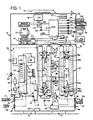
- housing 10 may be provided with a carrying handle 12 and ground engageable feet 14.
- the housing may be of a rectangular/cuboid type or other suitable shape. If desired, the housing 10 may be provided with ground engageable wheels or castors.
- the housing 10 is provided with a horizontal divider 16 which divides the housing into upper and lower sections 18, 20.
- the upper section 18 contains a transformer 22 which receives power from an external AC source 24 such as mains electricity via an on-off switch 25.
- the lower section 20 contains liquid ducting and processing components of the apparatus indicated generally at 26. Although liquid flow paths are shown, interconnecting conduit has been omitted.
- a voltage selector 27 is provided for mains voltages of, say 115v or 230 v.
- the housing 10 carries a coupling 28 for water from an external source, e.g. from a suitable mains 29, and a further coupling 30 which, in use, is connected to a suitable electrolyte source 31 such as a saline solution.
- a suitable electrolyte source 31 such as a saline solution.
- Water from source 29 then flows in the direction of the arrows to a solenoid valve 32 which receives electric current from a controller 34 in the upper section 18 of the housing, the controller 34 being arranged to receive power from the transformer 22.
- the controller 34 includes a printed circuit board carrying electronic components.
- An electrical switch 36 such as a press start switch is provided on the housing 10 for operating the solenoid valve 32.
- the solenoid valve 32 is normally closed when the power is switched off.
- a flow gauge 38 of known kind (for example available from CT Platon of Basingstoke England).
- a suitable flow gauge is the Model GI.
- a suitable flow-stat is the Model MN.
- the flow gauge 38 is calibrated, for example to allow water to flow therethrough at 0.2 - 1.5 litres per minute.
- the system shown in Fig 1 is preferably set to indicate a flow requirement of 1 to 1.5 litre per minute through the flow gauge 38.
- the flow-stat 40 is set to provide the desired flow rate of 1 to 1.5 litre per minute and will maintain a substantially constant flow irrespective of any change of pressure of the water entering through the inlet 28.
- the flow gauge 38 has a window 39 having flow rate graduations 39a at which the rate of flow is indicated.
- a flow switch 42 receives water from the flow-stat 40 and is sensitive to the rate of water flow.
- the switch 42 will remain open provided that the flow rate therethrough does not fall below a certain value, for example 0.8 litre per minute. However, should the flow rate fall below that value, the flow switch 42 will operate to shut off electricity supply from the controller 34 to the solenoid valve 32 and to two pairs of electrolysers 44, 44a and to a peristaltic pump 50 described below.
- switch 36 When switching on the apparatus from switch 25, switch 36 is pressed into an "on” position by-passing flow switch 42 and initiating water flow by operating the solenoid switch 32.
- the switch 36 is held in its "on” position long enough for a float in the switch 42 to lift from an open contact in the switch as water flows therethrough so that the switch 42 is then placed in a normal operating mode.
- water flows to an inlet 45 of a mixing chamber such as an T-junction 46 having a further inlet 48 which receives the saline solution entering through the coupling 30.
- a mixing chamber such as an T-junction 46 having a further inlet 48 which receives the saline solution entering through the coupling 30.
- the saline solution mixes with the water thereby providing an electrolyte.
- a mixture of 300 - 350 mg/l of brine per litre of water is drawn into the T-junction 46 to mix with the water.
- the mixture of water and electrolyte flow via a pressure switch 51, the operation of which is described below. From pressure switch 51, the mixture flows to a two-way valve 52 and then to junction 60, with supply outlets 62 of the junction 60 feeding mixture to junctions 63 and 63a for feeding the two respective pairs of electrolysers 44, 44a.
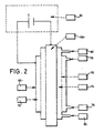
- One of the electrolysers of the pair 44 is shown in diagrammatic cross section in Fig 2 and comprises a tubular outer electrode 66 (the cathode), a rod like inner electrode 68 (the anode) spaced from the electrode 66 and a tubular diaphragm 70 arranged between the electrodes 66, 68 so as to divide the space therebetween into a cathode chamber 72 and an anode chamber 74.
- the diaphragm 70 may be made of a ceramic based on, for example, zirconium oxide, and is an ultra- filtering type.
- the electrolyser shown in Fig 2 is of a known kind and is preferably of the type disclosed in US Patent No. 5635040.
- the anode chamber 74 has an inlet 80 and an outlet 82 and the cathode chamber has an inlet 76 fed from junction 63 and an outlet 78.
- the anode 68 and cathode 66 receive electric current as shown from the controller 34 via leads 33.
- the liquid flow paths of the two electrolysers of each pair are connected in parallel.
- each cathode chamber 72 flows upwardly and leaves through the outlets 78, 78a.
- Junctions 83, 83a receive the liquid leaving the cathode chambers 72 as a catholyte and direct it to a four-way junction 84.
- the catholyte enters the junction 84 through substantially unrestricted inlets 85 and leaves through a restricted outlet 86 and a substantially unrestricted outlet 87.
- Catholyte passing through outlet 86 passes to an outlet 88 on the housing 10 via a flow adjuster 90. From the outlet 88, the catholyte can be collected in a suitable vessel.
- Catholyte passing through the outlet 87 passes to a Y junction 92 where the flow is split and directed to the inlets 80, 80a of junctions 79, 79a for the anode chambers 74 of electrolysers 44, 44a.
- the liquid flows upwardly through the anode chambers 74 and leaves as an anolyte through the outlets 82, 82a at the upper ends thereof. From there, the anolyte enters a further Y junction 94 which directs the anolyte to an outlet 96 on the housing 10 for collection in a suitable vessel 97.
- the first is an alkaline anolyte of pH 7-8.
- the procedure for making an alkaline anolyte is to shut off pinch valve 90 so directing all the alkaline catholyte solution made in the cathode chambers 72 for re-processing in the anode chambers 74.
- the second type of anolyte is a neutral anolyte of pH 6-7.
- the pinch valve 90 is opened slightly to allow a flow of catholyte to pass to outlet 88. The amount varies and should be adjusted to give a pH of 6-7. If the pH is above 7 the valve 90 is opened a little more and so the pH will drop. If the pH is below 6 the pinch valve 90 is open too far and should be closed a little.
- the third type of anolyte is an acid anolyte pH varying between 2 and 6.
- the valve 90 is opened fully to allow half the catholyte flow to pass to outlet 88 and half the flow to be directed into the anode chambers 72 of the electrolysers 44, 44a for activation and creation of the acidic anolyte. pH values for the various types of anolyte together with Redox readings are set out below.
- the fourth type of solution produced is catholyte with a pH of 11 to 12 and a Redox Potential of -600 to -900.
- the catholyte solutions also have processing applications and are collected from outlet 88.
- the valve 90 may be operated automatically as described below.
- the saline mixture is subjected to a voltage of 16 or 32 volts in the example shown.
- a three position voltage selector switch 106 (eg 16 volt position, 32 volt position and a centre OFF position) is provided for that purpose.
- the electrolysers 44, 44a may use about 50 watts each of electricity i.e. a total of 200 watts per hour at a reading of 10 amps shown at an LCD display 98 on the housing 10.
- the solenoid valve 32 is activated by a voltage of around 24 volts DC or AC
- the flow switch 42 operates and causes the controller 34 to shut off power to the electrolysers 44, 44a due to a fall in flow rate below a given rate, eg 0.8 l/min. An indication of that is provided by a lamp 110. This mode also cuts the power to the solenoid valve 32 to prevent water flow through the apparatus and the power to the peristaltic pump 50 is also shut down to prevent operation of the pump 50.
- a given rate eg 0.8 l/min.
- Cleaning is a very simple procedure.
- the pressure switch 51 will operate to prevent functioning of the apparatus when cleaning is imperative.
- To clean the apparatus the power is turned off with switch 25.
- the two-way valve 52 is turned to a cleaning position to allow cleaning solution to enter the apparatus through inlet 53 and prevent cleaning solution from entering the upstream water and saline flow paths. In that way cleaning solution is circulated only through the electrolysers 44, 44a and connecting pipe-work to normal outlets at 88 and 96.
- Cleaning solution is preferably 10% hydrochloric acid.
- Prior to introducing acid into the apparatus we prefer to drain out the liquid present in the electrolysers 44, 44a to prevent dilution and inactivation of the acid.
- Acid is then connected and fed into inlet 53 from a small external acid reservoir tank (not shown) and proceeds to the two-way valve 52 which directs it along normal downstream flow paths. From outlets 88 and 96 the acid can be piped back to the acid reservoir tank. Pinch valve 90 needs to be just partially open to ensure acid also circulates in the anode chambers of the electrolysers 44,44a. Acid is pumped until no gas bubbles are visible in the acid at outlets 88 and 96.
- the two-way valve 52 is then turned back to its original position. It is then necessary to pass the acid in the unit to waste and flush out the electrolysers 44,44a with clean water.
- the power is then restored to the apparatus by operating switch 25.
- a control panel switch 118 is then moved from a processing to a flushing position. That opens the solenoid valve 32 to allow only water to flow through the apparatus and flush out the acid for several minutes. To recommence processing of the water the switch 118 is restored to its processing position. When switch 118 is in the flushing position, an LED light 119 will illuminate. Where the pressure switch 51 operates to switch off the apparatus a lamp 112 associated with the switch 51 will flash.
- the salt used to make up a saline solution needs to be as pure as possible. Ideally a 99.9% pure salt is best and, by using such a salt, deposits in the electrolysers 44, 44a and connecting pipes will be greatly reduced.
- the apparatus is not powered during the cleaning operation and cleaning is a totally separate operation.
- the acid acting on the carbonates will generate gas bubbles at outlet 88 and 96 and cleaning is complete when the air bubbles stop flowing from that outlet
- a suction pipe 116 from the peristaltic pump 50 needs to be immersed in the water instead of a saline solution.
- An LCD display 98 provides an indication of current flow through the electrolysers 44, 44a. Flow of current through the electrolysers will be dependent upon the amount of saline in the mixture delivered to the electrolysers. As mentioned above, the saline solution is delivered to the T-junction 46 by the peristaltic pump 50.
- the apparatus can be operated either manually or automatically.
- switch 25 is operated to provide mains electricity to the transformer 22.
- the switch 36 is then operated so that water and saline begin to flow through the apparatus.
- the flow switch 42, pressure switch 51 and sensors 100 and 104 will operate to control operation of the apparatus as described above when working in the manual mode of operation.
- the system can operate automatically by providing an external Redox analyser 136 which receives 24 volts DC power from the controller 34 where indicated at 122.
- a pH analyser 138 is also connected to the controller 34. Both the Redox analyser 136 and the pH analyser 138 are set to sense desired Redox and pH values and are connected to probes (not shown) which sense the Redox value and the pH value of the solution being treated. Where the Redox level exceeds a preset level, a signal from the Redox analyser 136 will cause the controller 34 to switch off the apparatus downstream of switch 106 and to switch it on again when the Redox level falls below the present level. An LED 120 illuminates during that period.
- the pH analyser 138 will cause the controller 34 to alter the setting of flow adjuster 90 to change the pH value.
- An LED 139 illuminates when the pH probe is in use.
- a timer can be used instead of a Redox sensor and which is connected at 122 to the controller 34. The timer switches the apparatus on and off as required to maintain oxidant level in the treated solution.
- the two items can be replaced by a single flow control unit providing a fixed flow rate of fluid therethrough.
- Fig 3 shows a typical control sequence for the apparatus shown in Fig 1 and illustrates the way in which the system will be switched off in certain prevailing conditions and the operation of the various switches and sensors during the operation of the apparatus.
- Power regulators are provided to regulate the two voltages of 16 or 32 for the controller 34. To protect the power regulators cut-outs have been incorporated to operate at 16 Volts 15 amps and 32 Volts 11 amps. Should those current values be exceeded then the controller 34 will shut down power to the apparatus and an LED 124 will light up. To restore the power supply the controller 34 must be switched off at switch 25 and then switched on again.
- a 24 Volt DC supply is also available from the controller 34 to supply power to an external water pump for supplying liquid to the apparatus when mains water pressure is not available.
- the apparatus may be operated remotely with the switches 25, 36 and the various LED's and other indicators being arranged conveniently on a suitable remotely located console. The console can then be suitably connected electrically to the remainder of the apparatus.
- the apparatus in accordance with the invention can be made particularly compact and portable for easy movement of the apparatus from one place to another.
- the portable nature of the apparatus is useful when water purification is required at remote locations such as villages in third world countries where the apparatus can be used to purify a local water supply.
- the electricity supply 24 can be provided by means of a portable generator and water can be pumped, say, from the river to the inlet coupling 28 on the housing 10.
Landscapes
- Chemical & Material Sciences (AREA)
- Life Sciences & Earth Sciences (AREA)
- Hydrology & Water Resources (AREA)
- Engineering & Computer Science (AREA)
- Environmental & Geological Engineering (AREA)
- Water Supply & Treatment (AREA)
- Organic Chemistry (AREA)
- Chemical Kinetics & Catalysis (AREA)
- Electrochemistry (AREA)
- General Chemical & Material Sciences (AREA)
- Water Treatment By Electricity Or Magnetism (AREA)
Claims (29)
- Procédé de traitement électrochimique d'un électrolyte à base d'eau pour produire de l'eau potable ou des solutions de désinfection, de stérilisation ou de lavage/d'extraction, comprenant la fourniture d'un électrolyseur ayant des chambres cathodique et anodique, les chambres comprenant des électrodes respectives, fournissant une source de courant électrique pour les électrodes des chambres cathodique et anodique, fournissant à l'électrolyseur l'électrolyt devant être soumis au traitement électrochimique, caractérisé en ce qu'au moins une partie du catholyte de la chambre cathodique traverse la chambre anodique et le débit de ladite au moins une partie du catholyte de la chambre cathodique est ainsi altéré pour contrôler le pH de l'anolyte produit à partir de la chambre anodique, le reste suivant la direction d'une autre trajectoire.
- Procédé selon la revendication 1, dans lequel le pH de l'anolyte étant traité par le catholyte est mesuré et le débit du catholyte de la chambre cathodique vers la chambre anodique est ajusté en conséquence.
- Procédé selon la revendication 1 ou la revendication 2, dans lequel la valeur redox ou de l'oxydant de l'anolyte traité.par le catholyte est mesurée.
- Procédé selon la revendication 3, dans lequel le traitement de l'électrolyte est arrêté pour maintenir la valeur redox ou de l'oxydant et redémarré lorsque nécessaire.
- Procédé selon l'une quelconque des revendications précédentes, dans lequel le procédé comprend en outre l'étape consistant à détecter le moment où l'électrolyte a besoin d'être nettoyé et à nettoyer l'électrolyseur en rinçant avec un produit de nettoyage.
- Procédé selon la revendication 5, dans lequel le procédé de nettoyage comprend l'étape supplémentaire consistant à rincer l'électrolyseur avec de l'eau claire après l'avoir nettoyé avec une solution de nettoyage.
- Procédé selon l'une quelconque des revendications 1 à 4, dans lequel l'électrolyte à base d'eau comprend un mélange de saumure et d'eau.
- Procédé selon la revendication 7, dans lequel l'étape consistant à faire passer au moins une partie de l'électrolyte de la chambre cathodique vers la chambre anodique comprend l'étape consistant à faire s'écouler tout le catholyte de la chambre cathodique vers la chambre anodique de manière à produire une solution à partir de la chambre anodique qui soit alcaline, ayant un pH compris dans la plage allant de 7,5 à 9 et une valeur redox comprise dans la plage allant de +400 à +700 mV.
- Procédé selon la revendication 7, dans lequel l'étape consistant à faire passer au moins une partie de l'électrolyte de la chambre cathodique vers la chambre anodique comprend l'étape consistant à faire s'écouler une proportion relativement plus grande du catholyte de la chambre cathodique vers la chambre anodique de manière à produire une solution d'anolyte à partir de la chambre anodique ayant un pH sensiblement neutre compris dans la plage allant de 5,5 à 7,5 et une valeur redox comprise dans la plage allant de +600 à +900 mV.
- Procédé de traitement électrochimique d'un liquide selon la revendication 7, dans lequel l'étape consistant à faire passer au moins une partie du catholyte de la chambre cathodique vers la chambre anodique comprend l'étape consistant à faire s'écouler la moitié du catholyte de la chambre cathodique vers la chambre anodique de manière à produire une solution d'anolyte à partir de la chambre anodique ayant un pH acide compris dans la plage allant de 2 à 5,5 et une valeur redox comprise dans la plage allant de +900 à +1200 mV.
- Procédé selon la revendication 7, dans lequel l'étape consistant à faire passer au moins une partie du catholyte de la chambre cathodique vers la chambre anodique comprend l'étape consistant à faire s'écouler une proportion plus petite du catholyte de la chambre cathodique vers la chambre anodique, une proportion plus grande du catholyte dans la direction d'une autre trajectoire d'écoulement de manière à produire une solution de catholyte ayant un pH acide compris dans la plage allant de 11 à 12 et une valeur redox comprise dans la plage allant de -600 à -900 mV.
- Appareil de traitement électrochimique d'un électrolyte à base d'eau comprenant un électrolyseur ayant des chambres cathodique et anodique, des moyens pour fournir une source de courant électrique pour les électrodes des chambres, des moyens pour faire s'écouler au moins en partie le catholyte de la chambre cathodique vers la chambre anodique, des moyens pour faire suivre la direction d'une autre trajectoire au reste, et des moyens pour altérer le débit du catholyte traversant la chambre anodique à partir de la chambre cathodique pour contrôler le pH de l'anolyte.
- Appareil selon la revendication 12, dans lequel l'autre trajectoire comprend des moyens de contrôle du débit, tels qu'un régulateur de débit, pour contrôler le débit le long de l'autre trajectoire.
- Appareil selon la revendication 12 ou la revendication 13, dans lequel les moyens mentionnés ci-dessus pour faire s'écouler au moins en partie le catholyte de la chambre cathodique vers le chambre anodique et en partie le long de l'autre trajectoire comprennent un dispositif ayant une admission sensiblement non limitée pour le catholyte de ladite chambre cathodique et une première et une seconde sortie, l'une d'elles pouvant fournir une meilleure résistance au débit que l'autre.
- Appareil selon l'une quelconque des revendications 12, 13 ou 14 muni de moyens de détection pour détecter la valeur du pH de l'anolyte étant traité par le catholyte et de moyens de contrôle, tels que les moyens de contrôle du débit mentionnés ci-dessus, pour contrôler le débit du catholyte le long de l'autre trajectoire, de manière à ce que si la valeur du pH change par rapport à une valeur prédéterminée, les moyens de contrôle altèrent le débit du catholyte de la chambre cathodique vers la chambre anodique de l'électrolyseur.
- Appareil selon l'une quelconque des revendications 12 à 15, dans lequel des moyens sont fournis pour détecter la valeur redox de l'anolyte étant traité par le catholyte, moyennant quoi si la valeur relox change par rapport à une valeur prédéterminée, le traitement de l'électroly est arrêté pour maintenir la valeur redox de l'anolyte traité, puis redémarré lorsque nécessaire.
- Appareil selon l'une quelconque des revendications 12 à 16, comprenant en outre une pompe pour aspirer l'électolyte à partir d'un point d'alimentation.
- Appareil selon la revendication 17, dans lequel la pompe est une pompe péristaltique.
- Appareil selon l'une quelconque des revendications 12 à 18, comprenant en outre un dispositif de mélange, tel qu'une jonction en T, qui reçoit l'eau et une solution saline destinée à être mélangée avec l'eau pour former l'électrolyte à base d'eau, la solution saline et l'eau étant mélangés ensemble dans le dispositif de mélange.
- Appareil selon l'une quelconque des revendications 12 à 19, dans lequel des moyens sont prévus pour signaler le moment où il est nécessaire de nettoyer l'appareil lorsque la résistance au débit augmente en raison de l'apparition de tartre.
- Appareil selon l'une quelconque des revendications 12 à 20, dans lequel un dispositif de mélange est prévu pour mélanger l'eau et l'électrolyte et dans lequel des moyens de nettoyage sont prévus pour introduire une solution de nettoyage dans l'appareil de manière à ce que la solution de nettoyage s'écoule à travers une partie sélectionnée de l'appareil de préférence en aval du dispositif de mélange.
- Appareil selon la revendication 21, dans lequel lesdits moyens de nettoyage comprennent des moyens de soupape pour introduire la solution de nettoyage à partir d'une source adaptée.
- Appareil selon l'une quelconque des revendications 12 à 22, dans lequel un dispositif d'aspiration, tel qu'un vortex, est fourni pour aspirer le catholyte, qui s'écoule à travers l'autre trajectoire mentionnée ci-dessus, le long de la trajectoire.
- Appareil selon la revendication 23, dans lequel une soupape de retenue est fournie au niveau de la trajectoire pour le liquide qui s'écoule en partie vers la chambre anodique de l'électrolyseur pour empêcher que le dispositif d'aspiration n'aspirer le liquide à travers l'électrolyseur dans le sens inverse.
- Appareil selon la revendication 24, dans lequel une soupape de retenue est prévue au niveau de la trajectoire pour la catholyte qui s'écoule en partie vers la chambre anodique de l'électrolyseur pour empêcher que le dispositif d'aspiration n'aspire le liquide à travers l'électrolyseur dans le sens inverse.
- Appareil selon l'une quelconque des revendications 12 à 25, dans lequel deux paires d'électrolyseurs sont fournies.
- Appareil selon la revendication 26, dans lequel les deux paires d'électrolyseurs sont reliées de manière à ce que les chambres anodiques soient reliées l'une à l'autre en parallèle et que les chambres cathodiques soient reliées l'une à l'autre en parallèle.
- Appareil selon l'une quelconque des revendications 12 à 27, dans lequel l'appareil est portatif.
- Appareil selon la revendication 28 prévu dans un logement ayant des admissions adaptées pour l'eau et un électrolyte et des sorties respectives adaptées pour l'anolyte ou le catholyte requis et les produits secondaires de l'électrolyseur.
Applications Claiming Priority (3)
| Application Number | Priority Date | Filing Date | Title |
|---|---|---|---|
| GB9620167 | 1996-09-27 | ||
| GBGB9620167.8A GB9620167D0 (en) | 1996-09-27 | 1996-09-27 | Electrochemical processing of liquid such as water |
| PCT/GB1997/002666 WO1998013304A1 (fr) | 1996-09-27 | 1997-09-29 | Traitement electrochimique d'un liquide tel que l'eau |
Publications (2)
| Publication Number | Publication Date |
|---|---|
| EP1007478A1 EP1007478A1 (fr) | 2000-06-14 |
| EP1007478B1 true EP1007478B1 (fr) | 2003-08-20 |
Family
ID=10800587
Family Applications (1)
| Application Number | Title | Priority Date | Filing Date |
|---|---|---|---|
| EP97943068A Expired - Lifetime EP1007478B1 (fr) | 1996-09-27 | 1997-09-29 | Traitement electrochimique d'un liquide tel que l'eau |
Country Status (8)
| Country | Link |
|---|---|
| EP (1) | EP1007478B1 (fr) |
| AT (1) | ATE247604T1 (fr) |
| AU (1) | AU741543B2 (fr) |
| CA (1) | CA2267265C (fr) |
| DE (1) | DE69724289T2 (fr) |
| GB (1) | GB9620167D0 (fr) |
| MX (1) | MXPA99002941A (fr) |
| WO (1) | WO1998013304A1 (fr) |
Cited By (2)
| Publication number | Priority date | Publication date | Assignee | Title |
|---|---|---|---|---|
| DE102014010901A1 (de) | 2014-07-24 | 2016-01-28 | Michael Saefkow | ECA Reaktor zur Erzeugung eines aktivierten hypochlorithaltigen Desinfektionsmittels |
| DE102017214810A1 (de) | 2017-08-24 | 2019-02-28 | Gabriele Keddo | Vorrichtung und Verfahren zur Wasserdesinfektion und Herstellung eines Desinfektionsmittels |
Families Citing this family (19)
| Publication number | Priority date | Publication date | Assignee | Title |
|---|---|---|---|---|
| JPH1157720A (ja) * | 1996-11-07 | 1999-03-02 | Honda Motor Co Ltd | 電解機能水、その製造方法及び製造装置 |
| DE60036582T2 (de) | 1999-08-06 | 2008-06-26 | Puricore International Ltd. | Elektrochemische Behandlung einer wässrigen Lösung |
| EP1579037A4 (fr) | 2002-03-06 | 2008-02-13 | Univ Georgia Res Found | Procede et appareil d'electrolyse de l'eau |
| WO2007048772A1 (fr) | 2005-10-28 | 2007-05-03 | Akuatech S.R.L. | C02f 1/461 title: nouvelle solution aqueuse de stabilite elevee, electrode comportant un nanorevetement pour la preparation de la solution et procede de fabrication de cette electrode |
| GB2436330A (en) * | 2006-03-20 | 2007-09-26 | Christian Jean Gauthier | A cleaning system for an electrode |
| US20080116144A1 (en) | 2006-10-10 | 2008-05-22 | Spicer Randolph, Llc | Methods and compositions for reducing chlorine demand, decreasing disinfection by-products and controlling deposits in drinking water distribution systems |
| EP2162140B1 (fr) | 2007-04-25 | 2013-05-29 | APR Nanotechnologies S.A. | Eau electrolytique extremement stable a largeur de raie a mi-hauteur de rmn reduite |
| EP2954901A1 (fr) | 2009-06-17 | 2015-12-16 | APR Nanotechnologies S.A. | Methodes de traitement des troubles de l'oeil exterene au moyen d''eau acide a potentiel d'oxydo-reduction eleve et compositions associees |
| EP2632857A4 (fr) * | 2010-10-28 | 2016-01-13 | Anolytech Ab | Procédé et système pour la production d'une fraction anolytique |
| US9162904B2 (en) | 2011-03-04 | 2015-10-20 | Tennant Company | Cleaning solution generator |
| US8882972B2 (en) | 2011-07-19 | 2014-11-11 | Ecolab Usa Inc | Support of ion exchange membranes |
| US8562810B2 (en) | 2011-07-26 | 2013-10-22 | Ecolab Usa Inc. | On site generation of alkalinity boost for ware washing applications |
| WO2013064688A2 (fr) | 2011-11-04 | 2013-05-10 | Lohas Products Gmbh | Procédé de préparation d'une solution à base d'eau activée par voie électrochimique |
| WO2013064694A2 (fr) | 2011-11-04 | 2013-05-10 | Lohas Products Gmbh | Procédé de production d'un électrolyte |
| WO2013064695A2 (fr) | 2011-11-04 | 2013-05-10 | Lohas Products Gmbh | Procédé de préparation d'un liquide anolyte |
| WO2013068599A2 (fr) | 2011-11-11 | 2013-05-16 | Lohas Products Gmbh | Procédé pour la production d'une composition d'anolyte |
| WO2013121026A2 (fr) | 2012-02-16 | 2013-08-22 | Lohas Products Gmbh | Traitement intermittent avec un agent oxydant et un agent réducteur |
| US9556526B2 (en) | 2012-06-29 | 2017-01-31 | Tennant Company | Generator and method for forming hypochlorous acid |
| US9487870B2 (en) | 2012-07-11 | 2016-11-08 | Ecolab Usa Inc. | Apparatus, method and system for rapid service, removal and replacement of an electrolytic cell |
Family Cites Families (8)
| Publication number | Priority date | Publication date | Assignee | Title |
|---|---|---|---|---|
| US4904357A (en) * | 1989-05-30 | 1990-02-27 | Southwestern Analytical | Production of quaternary ammonium and quaternary phosphonium borohydrides |
| EP0474936A1 (fr) * | 1990-09-14 | 1992-03-18 | The State Of Israel, Atomic Energy Commission, Nuclear Research Center Negev | Procédé électrochimique pour la purification des déchets contenant du chrome |
| WO1993010051A1 (fr) * | 1991-11-22 | 1993-05-27 | Techno Excel Kabushiki Kaisha | Appareil de production d'eau electrolytique |
| GB2274113B (en) * | 1992-04-03 | 1996-05-15 | Bakhir Vitold M | Apparatus for electrochemical treatment of water |
| ES2115156T3 (es) * | 1993-02-22 | 1998-06-16 | Nippon Intek Co Ltd | Procedimiento y dispositivo para producir agua electrolitica. |
| JP3363248B2 (ja) * | 1994-03-31 | 2003-01-08 | ジプコム株式会社 | 殺菌水、その製造法及び製造装置 |
| JP3440594B2 (ja) * | 1994-12-22 | 2003-08-25 | 松下電工株式会社 | 電解水生成装置 |
| US5628888A (en) * | 1996-03-28 | 1997-05-13 | Rscecat, Usa, Inc. | Apparatus for electrochemical treatment of water and/or water solutions |
-
1996
- 1996-09-27 GB GBGB9620167.8A patent/GB9620167D0/en active Pending
-
1997
- 1997-09-29 MX MXPA99002941A patent/MXPA99002941A/es unknown
- 1997-09-29 AT AT97943068T patent/ATE247604T1/de not_active IP Right Cessation
- 1997-09-29 AU AU44682/97A patent/AU741543B2/en not_active Ceased
- 1997-09-29 CA CA2267265A patent/CA2267265C/fr not_active Expired - Lifetime
- 1997-09-29 DE DE69724289T patent/DE69724289T2/de not_active Expired - Lifetime
- 1997-09-29 EP EP97943068A patent/EP1007478B1/fr not_active Expired - Lifetime
- 1997-09-29 WO PCT/GB1997/002666 patent/WO1998013304A1/fr not_active Ceased
Cited By (2)
| Publication number | Priority date | Publication date | Assignee | Title |
|---|---|---|---|---|
| DE102014010901A1 (de) | 2014-07-24 | 2016-01-28 | Michael Saefkow | ECA Reaktor zur Erzeugung eines aktivierten hypochlorithaltigen Desinfektionsmittels |
| DE102017214810A1 (de) | 2017-08-24 | 2019-02-28 | Gabriele Keddo | Vorrichtung und Verfahren zur Wasserdesinfektion und Herstellung eines Desinfektionsmittels |
Also Published As
| Publication number | Publication date |
|---|---|
| DE69724289T2 (de) | 2004-05-27 |
| EP1007478A1 (fr) | 2000-06-14 |
| CA2267265C (fr) | 2010-08-03 |
| AU4468297A (en) | 1998-04-17 |
| DE69724289D1 (de) | 2003-09-25 |
| AU741543B2 (en) | 2001-12-06 |
| MXPA99002941A (es) | 2004-12-02 |
| GB9620167D0 (en) | 1996-11-13 |
| ATE247604T1 (de) | 2003-09-15 |
| WO1998013304A1 (fr) | 1998-04-02 |
| CA2267265A1 (fr) | 1998-04-02 |
Similar Documents
| Publication | Publication Date | Title |
|---|---|---|
| EP1007478B1 (fr) | Traitement electrochimique d'un liquide tel que l'eau | |
| US4097356A (en) | Chlorine generator | |
| KR101708702B1 (ko) | 전기 화학적 폐수 처리 장치 및 방법 | |
| US6296744B1 (en) | Apparatus for the electrochemical treatment of a liquid medium | |
| EP0768279A1 (fr) | Procede et appareil pour l'electrolyse de l'eau | |
| CA2270402A1 (fr) | Procede et appareil pour la production d'eau oxygenee | |
| WO2012145645A1 (fr) | Production indépendante d'eau acide électrolysée et d'eau basique électrolysée | |
| EP2569254B1 (fr) | Dispositif de production d'une solution electrochimiquement activé par un procédé d'électrolyse | |
| JP2022505099A (ja) | 酸化剤水溶液の合成のための電気化学システム | |
| EP1461291A1 (fr) | Dispositif electrolytique et procede de desinfection de l'eau dans un systeme d'approvisionnement en eau par la generation de chlore actif | |
| CN210313851U (zh) | 一种冲洗节能的电除盐装置 | |
| JP3319841B2 (ja) | 電解水生成装置 | |
| JPH06206074A (ja) | 殺菌水の製造方法及び装置 | |
| CN209864716U (zh) | 一种用于蒸汽灭菌器的自动供水系统 | |
| CN212403814U (zh) | 一种适用高硬度水质的新型水处理设备 | |
| JPH07163982A (ja) | 貯留水の電解消毒装置 | |
| EP1226094A1 (fr) | Dispositif pour electrolyse | |
| JP4936423B2 (ja) | 電解水生成装置及びそれを備えた流し台 | |
| KR20080059860A (ko) | 광천수로부터 음료수를 제조하는 방법 | |
| CN208791246U (zh) | 一种工业废水中高浓度cod的间歇式处理系统 | |
| JPH1157713A (ja) | アルカリイオン整水器 | |
| JPH10314744A (ja) | アルカリイオン整水器 | |
| JPH06238280A (ja) | 電解整水方法及び装置 | |
| SU842036A1 (ru) | Способ автоматического регулировани пРОцЕССОМ элЕКТРОХиМичЕСКОй ОчиСТКиСТОчНыХ ВОд | |
| EP1630137A1 (fr) | Systeme pour produire de l'eau minerale |
Legal Events
| Date | Code | Title | Description |
|---|---|---|---|
| PUAI | Public reference made under article 153(3) epc to a published international application that has entered the european phase |
Free format text: ORIGINAL CODE: 0009012 |
|
| 17P | Request for examination filed |
Effective date: 19990730 |
|
| AK | Designated contracting states |
Kind code of ref document: A1 Designated state(s): AT BE CH DE DK ES FI FR GB GR IE IT LI LU MC NL PT SE |
|
| 17Q | First examination report despatched |
Effective date: 20001026 |
|
| RAP1 | Party data changed (applicant data changed or rights of an application transferred) |
Owner name: STERILOX TECHNOLOGIES INTERNATIONAL LIMITED |
|
| GRAH | Despatch of communication of intention to grant a patent |
Free format text: ORIGINAL CODE: EPIDOS IGRA |
|
| GRAH | Despatch of communication of intention to grant a patent |
Free format text: ORIGINAL CODE: EPIDOS IGRA |
|
| GRAA | (expected) grant |
Free format text: ORIGINAL CODE: 0009210 |
|
| AK | Designated contracting states |
Designated state(s): AT BE CH DE DK ES FI FR GB GR IE IT LI LU MC NL PT SE |
|
| PG25 | Lapsed in a contracting state [announced via postgrant information from national office to epo] |
Ref country code: NL Free format text: LAPSE BECAUSE OF FAILURE TO SUBMIT A TRANSLATION OF THE DESCRIPTION OR TO PAY THE FEE WITHIN THE PRESCRIBED TIME-LIMIT Effective date: 20030820 Ref country code: LI Free format text: LAPSE BECAUSE OF FAILURE TO SUBMIT A TRANSLATION OF THE DESCRIPTION OR TO PAY THE FEE WITHIN THE PRESCRIBED TIME-LIMIT Effective date: 20030820 Ref country code: FI Free format text: LAPSE BECAUSE OF FAILURE TO SUBMIT A TRANSLATION OF THE DESCRIPTION OR TO PAY THE FEE WITHIN THE PRESCRIBED TIME-LIMIT Effective date: 20030820 Ref country code: CH Free format text: LAPSE BECAUSE OF FAILURE TO SUBMIT A TRANSLATION OF THE DESCRIPTION OR TO PAY THE FEE WITHIN THE PRESCRIBED TIME-LIMIT Effective date: 20030820 Ref country code: BE Free format text: LAPSE BECAUSE OF FAILURE TO SUBMIT A TRANSLATION OF THE DESCRIPTION OR TO PAY THE FEE WITHIN THE PRESCRIBED TIME-LIMIT Effective date: 20030820 Ref country code: AT Free format text: LAPSE BECAUSE OF FAILURE TO SUBMIT A TRANSLATION OF THE DESCRIPTION OR TO PAY THE FEE WITHIN THE PRESCRIBED TIME-LIMIT Effective date: 20030820 |
|
| REG | Reference to a national code |
Ref country code: GB Ref legal event code: FG4D |
|
| REG | Reference to a national code |
Ref country code: CH Ref legal event code: EP |
|
| REG | Reference to a national code |
Ref country code: IE Ref legal event code: FG4D |
|
| REF | Corresponds to: |
Ref document number: 69724289 Country of ref document: DE Date of ref document: 20030925 Kind code of ref document: P |
|
| PG25 | Lapsed in a contracting state [announced via postgrant information from national office to epo] |
Ref country code: LU Free format text: LAPSE BECAUSE OF NON-PAYMENT OF DUE FEES Effective date: 20030929 Ref country code: IE Free format text: LAPSE BECAUSE OF NON-PAYMENT OF DUE FEES Effective date: 20030929 |
|
| PG25 | Lapsed in a contracting state [announced via postgrant information from national office to epo] |
Ref country code: MC Free format text: LAPSE BECAUSE OF NON-PAYMENT OF DUE FEES Effective date: 20030930 |
|
| PG25 | Lapsed in a contracting state [announced via postgrant information from national office to epo] |
Ref country code: SE Free format text: LAPSE BECAUSE OF FAILURE TO SUBMIT A TRANSLATION OF THE DESCRIPTION OR TO PAY THE FEE WITHIN THE PRESCRIBED TIME-LIMIT Effective date: 20031120 Ref country code: GR Free format text: LAPSE BECAUSE OF FAILURE TO SUBMIT A TRANSLATION OF THE DESCRIPTION OR TO PAY THE FEE WITHIN THE PRESCRIBED TIME-LIMIT Effective date: 20031120 Ref country code: DK Free format text: LAPSE BECAUSE OF FAILURE TO SUBMIT A TRANSLATION OF THE DESCRIPTION OR TO PAY THE FEE WITHIN THE PRESCRIBED TIME-LIMIT Effective date: 20031120 |
|
| PG25 | Lapsed in a contracting state [announced via postgrant information from national office to epo] |
Ref country code: ES Free format text: LAPSE BECAUSE OF FAILURE TO SUBMIT A TRANSLATION OF THE DESCRIPTION OR TO PAY THE FEE WITHIN THE PRESCRIBED TIME-LIMIT Effective date: 20031201 |
|
| PG25 | Lapsed in a contracting state [announced via postgrant information from national office to epo] |
Ref country code: PT Free format text: LAPSE BECAUSE OF FAILURE TO SUBMIT A TRANSLATION OF THE DESCRIPTION OR TO PAY THE FEE WITHIN THE PRESCRIBED TIME-LIMIT Effective date: 20040120 |
|
| NLV1 | Nl: lapsed or annulled due to failure to fulfill the requirements of art. 29p and 29m of the patents act | ||
| REG | Reference to a national code |
Ref country code: CH Ref legal event code: PL |
|
| ET | Fr: translation filed | ||
| PLBE | No opposition filed within time limit |
Free format text: ORIGINAL CODE: 0009261 |
|
| STAA | Information on the status of an ep patent application or granted ep patent |
Free format text: STATUS: NO OPPOSITION FILED WITHIN TIME LIMIT |
|
| REG | Reference to a national code |
Ref country code: IE Ref legal event code: MM4A |
|
| 26N | No opposition filed |
Effective date: 20040524 |
|
| PG25 | Lapsed in a contracting state [announced via postgrant information from national office to epo] |
Ref country code: IT Free format text: LAPSE BECAUSE OF NON-PAYMENT OF DUE FEES;WARNING: LAPSES OF ITALIAN PATENTS WITH EFFECTIVE DATE BEFORE 2007 MAY HAVE OCCURRED AT ANY TIME BEFORE 2007. THE CORRECT EFFECTIVE DATE MAY BE DIFFERENT FROM THE ONE RECORDED. Effective date: 20050929 |
|
| PG25 | Lapsed in a contracting state [announced via postgrant information from national office to epo] |
Ref country code: DE Free format text: LAPSE BECAUSE OF NON-PAYMENT OF DUE FEES Effective date: 20060401 |
|
| PG25 | Lapsed in a contracting state [announced via postgrant information from national office to epo] |
Ref country code: FR Free format text: LAPSE BECAUSE OF NON-PAYMENT OF DUE FEES Effective date: 20060531 |
|
| REG | Reference to a national code |
Ref country code: FR Ref legal event code: ST Effective date: 20060531 |
|
| REG | Reference to a national code |
Ref country code: FR Ref legal event code: RN |
|
| REG | Reference to a national code |
Ref country code: FR Ref legal event code: CD |
|
| REG | Reference to a national code |
Ref country code: FR Ref legal event code: FC |
|
| PGRI | Patent reinstated in contracting state [announced from national office to epo] |
Ref country code: FR Effective date: 20061025 |
|
| PGRI | Patent reinstated in contracting state [announced from national office to epo] |
Ref country code: IT Effective date: 20080801 |
|
| REG | Reference to a national code |
Ref country code: GB Ref legal event code: 732E Free format text: REGISTERED BETWEEN 20110224 AND 20110302 |
|
| REG | Reference to a national code |
Ref country code: FR Ref legal event code: TP |
|
| REG | Reference to a national code |
Ref country code: DE Ref legal event code: R081 Ref document number: 69724289 Country of ref document: DE Owner name: PURICORE, INC., MALVERN, US Free format text: FORMER OWNER: PURICORE INTERNATIONAL LTD., ABINGDON, OXFORDSHIRE, GB Effective date: 20110315 |
|
| REG | Reference to a national code |
Ref country code: FR Ref legal event code: PLFP Year of fee payment: 20 |
|
| PGFP | Annual fee paid to national office [announced via postgrant information from national office to epo] |
Ref country code: GB Payment date: 20160927 Year of fee payment: 20 Ref country code: IT Payment date: 20160921 Year of fee payment: 20 |
|
| PGFP | Annual fee paid to national office [announced via postgrant information from national office to epo] |
Ref country code: FR Payment date: 20160926 Year of fee payment: 20 |
|
| PGFP | Annual fee paid to national office [announced via postgrant information from national office to epo] |
Ref country code: DE Payment date: 20160928 Year of fee payment: 20 |
|
| REG | Reference to a national code |
Ref country code: DE Ref legal event code: R071 Ref document number: 69724289 Country of ref document: DE |
|
| REG | Reference to a national code |
Ref country code: GB Ref legal event code: PE20 Expiry date: 20170928 |
|
| PG25 | Lapsed in a contracting state [announced via postgrant information from national office to epo] |
Ref country code: GB Free format text: LAPSE BECAUSE OF EXPIRATION OF PROTECTION Effective date: 20170928 |