EP1006885B1 - Vorrichtung zur behandlung von zwischenwirbelscheiben - Google Patents
Vorrichtung zur behandlung von zwischenwirbelscheiben Download PDFInfo
- Publication number
- EP1006885B1 EP1006885B1 EP97912882A EP97912882A EP1006885B1 EP 1006885 B1 EP1006885 B1 EP 1006885B1 EP 97912882 A EP97912882 A EP 97912882A EP 97912882 A EP97912882 A EP 97912882A EP 1006885 B1 EP1006885 B1 EP 1006885B1
- Authority
- EP
- European Patent Office
- Prior art keywords
- catheter
- intradiscal section
- disc
- introducer
- delivery device
- Prior art date
- Legal status (The legal status is an assumption and is not a legal conclusion. Google has not performed a legal analysis and makes no representation as to the accuracy of the status listed.)
- Expired - Lifetime
Links
- 238000011282 treatment Methods 0.000 claims abstract description 19
- 239000000126 substance Substances 0.000 claims abstract description 6
- 239000000463 material Substances 0.000 claims description 94
- 238000010438 heat treatment Methods 0.000 claims description 76
- 238000005452 bending Methods 0.000 claims description 74
- 206010016654 Fibrosis Diseases 0.000 claims description 39
- 230000004761 fibrosis Effects 0.000 claims description 36
- 102000008186 Collagen Human genes 0.000 claims description 32
- 108010035532 Collagen Proteins 0.000 claims description 32
- 229920001436 collagen Polymers 0.000 claims description 32
- 239000013078 crystal Substances 0.000 claims description 16
- 108090000790 Enzymes Proteins 0.000 claims description 10
- 102000004190 Enzymes Human genes 0.000 claims description 10
- 229940088598 enzyme Drugs 0.000 claims description 10
- 108090000190 Thrombin Proteins 0.000 claims description 8
- 229960004072 thrombin Drugs 0.000 claims description 8
- 108010049003 Fibrinogen Proteins 0.000 claims description 7
- 102000008946 Fibrinogen Human genes 0.000 claims description 7
- 229940012952 fibrinogen Drugs 0.000 claims description 7
- 239000000523 sample Substances 0.000 claims description 7
- 239000000243 solution Substances 0.000 claims description 7
- 239000000853 adhesive Substances 0.000 claims description 6
- 230000001070 adhesive effect Effects 0.000 claims description 6
- 208000037265 diseases, disorders, signs and symptoms Diseases 0.000 claims description 6
- 239000004568 cement Substances 0.000 claims description 5
- 238000001514 detection method Methods 0.000 claims description 5
- 239000002872 contrast media Substances 0.000 claims description 4
- 229940039231 contrast media Drugs 0.000 claims description 4
- 230000002262 irrigation Effects 0.000 claims description 4
- 238000003973 irrigation Methods 0.000 claims description 4
- 230000007903 penetration ability Effects 0.000 claims description 4
- 239000008177 pharmaceutical agent Substances 0.000 claims description 4
- 238000002604 ultrasonography Methods 0.000 claims description 4
- 201000010099 disease Diseases 0.000 claims description 3
- 239000000017 hydrogel Substances 0.000 claims description 3
- 239000013307 optical fiber Substances 0.000 claims description 3
- 230000008878 coupling Effects 0.000 claims description 2
- 238000010168 coupling process Methods 0.000 claims description 2
- 238000005859 coupling reaction Methods 0.000 claims description 2
- 230000002138 osteoinductive effect Effects 0.000 claims description 2
- 238000005096 rolling process Methods 0.000 claims description 2
- 229910001285 shape-memory alloy Inorganic materials 0.000 claims description 2
- 229960005188 collagen Drugs 0.000 claims 1
- 238000009413 insulation Methods 0.000 claims 1
- 238000012544 monitoring process Methods 0.000 claims 1
- 238000000034 method Methods 0.000 abstract description 57
- 229910001220 stainless steel Inorganic materials 0.000 description 28
- 239000010935 stainless steel Substances 0.000 description 28
- 210000001519 tissue Anatomy 0.000 description 28
- 239000004642 Polyimide Substances 0.000 description 26
- 229920001721 polyimide Polymers 0.000 description 26
- 208000002193 Pain Diseases 0.000 description 20
- 230000006870 function Effects 0.000 description 17
- 230000007704 transition Effects 0.000 description 16
- BASFCYQUMIYNBI-UHFFFAOYSA-N platinum Chemical compound [Pt] BASFCYQUMIYNBI-UHFFFAOYSA-N 0.000 description 14
- XLYOFNOQVPJJNP-UHFFFAOYSA-N water Substances O XLYOFNOQVPJJNP-UHFFFAOYSA-N 0.000 description 13
- 210000005036 nerve Anatomy 0.000 description 12
- 230000003412 degenerative effect Effects 0.000 description 11
- 206010061246 Intervertebral disc degeneration Diseases 0.000 description 10
- 230000008569 process Effects 0.000 description 10
- 238000010586 diagram Methods 0.000 description 9
- 238000003780 insertion Methods 0.000 description 9
- 230000037431 insertion Effects 0.000 description 9
- 206010063560 Excessive granulation tissue Diseases 0.000 description 8
- 239000004952 Polyamide Substances 0.000 description 8
- 238000013461 design Methods 0.000 description 8
- 230000004927 fusion Effects 0.000 description 8
- 239000000499 gel Substances 0.000 description 8
- 210000001126 granulation tissue Anatomy 0.000 description 8
- 230000033001 locomotion Effects 0.000 description 8
- 229910052751 metal Inorganic materials 0.000 description 8
- 239000002184 metal Substances 0.000 description 8
- 239000002858 neurotransmitter agent Substances 0.000 description 8
- 229920002647 polyamide Polymers 0.000 description 8
- 230000000007 visual effect Effects 0.000 description 8
- PXHVJJICTQNCMI-UHFFFAOYSA-N Nickel Chemical compound [Ni] PXHVJJICTQNCMI-UHFFFAOYSA-N 0.000 description 7
- 238000013459 approach Methods 0.000 description 7
- 230000001965 increasing effect Effects 0.000 description 7
- 229910052697 platinum Inorganic materials 0.000 description 7
- 208000003618 Intervertebral Disc Displacement Diseases 0.000 description 6
- 230000008859 change Effects 0.000 description 6
- 230000007423 decrease Effects 0.000 description 6
- 230000000694 effects Effects 0.000 description 6
- 229920001296 polysiloxane Polymers 0.000 description 6
- 239000007787 solid Substances 0.000 description 6
- 210000001032 spinal nerve Anatomy 0.000 description 6
- XEEYBQQBJWHFJM-UHFFFAOYSA-N Iron Chemical compound [Fe] XEEYBQQBJWHFJM-UHFFFAOYSA-N 0.000 description 5
- 230000009471 action Effects 0.000 description 5
- 230000008901 benefit Effects 0.000 description 5
- 239000004020 conductor Substances 0.000 description 5
- 230000009977 dual effect Effects 0.000 description 5
- 238000001125 extrusion Methods 0.000 description 5
- 239000012530 fluid Substances 0.000 description 5
- 238000001802 infusion Methods 0.000 description 5
- 230000001537 neural effect Effects 0.000 description 5
- 239000004033 plastic Substances 0.000 description 5
- 229920003023 plastic Polymers 0.000 description 5
- 239000000565 sealant Substances 0.000 description 5
- 230000001225 therapeutic effect Effects 0.000 description 5
- 239000010963 304 stainless steel Substances 0.000 description 4
- VLHUSFYMPUDOEL-WZTVWXICSA-N Iothalamate meglumine Chemical compound CNC[C@H](O)[C@@H](O)[C@H](O)[C@H](O)CO.CNC(=O)C1=C(I)C(NC(C)=O)=C(I)C(C(O)=O)=C1I VLHUSFYMPUDOEL-WZTVWXICSA-N 0.000 description 4
- 229910000589 SAE 304 stainless steel Inorganic materials 0.000 description 4
- TZCXTZWJZNENPQ-UHFFFAOYSA-L barium sulfate Chemical compound [Ba+2].[O-]S([O-])(=O)=O TZCXTZWJZNENPQ-UHFFFAOYSA-L 0.000 description 4
- 238000005520 cutting process Methods 0.000 description 4
- 208000018180 degenerative disc disease Diseases 0.000 description 4
- 239000008151 electrolyte solution Substances 0.000 description 4
- 239000000835 fiber Substances 0.000 description 4
- 239000000945 filler Substances 0.000 description 4
- PCHJSUWPFVWCPO-UHFFFAOYSA-N gold Chemical compound [Au] PCHJSUWPFVWCPO-UHFFFAOYSA-N 0.000 description 4
- 229910052737 gold Inorganic materials 0.000 description 4
- 239000010931 gold Substances 0.000 description 4
- 238000003384 imaging method Methods 0.000 description 4
- 208000021600 intervertebral disc degenerative disease Diseases 0.000 description 4
- -1 polyethylene Polymers 0.000 description 4
- 238000004382 potting Methods 0.000 description 4
- 238000012360 testing method Methods 0.000 description 4
- 108090001069 Chymopapain Proteins 0.000 description 3
- ISWQCIVKKSOKNN-UHFFFAOYSA-L Tiron Chemical compound [Na+].[Na+].OC1=CC(S([O-])(=O)=O)=CC(S([O-])(=O)=O)=C1O ISWQCIVKKSOKNN-UHFFFAOYSA-L 0.000 description 3
- 238000002679 ablation Methods 0.000 description 3
- 230000005856 abnormality Effects 0.000 description 3
- 229910045601 alloy Inorganic materials 0.000 description 3
- 239000000956 alloy Substances 0.000 description 3
- 210000003484 anatomy Anatomy 0.000 description 3
- 229960002976 chymopapain Drugs 0.000 description 3
- 230000006378 damage Effects 0.000 description 3
- 230000003247 decreasing effect Effects 0.000 description 3
- 230000002638 denervation Effects 0.000 description 3
- 230000001066 destructive effect Effects 0.000 description 3
- 208000035475 disorder Diseases 0.000 description 3
- 239000002657 fibrous material Substances 0.000 description 3
- 208000014674 injury Diseases 0.000 description 3
- 230000010354 integration Effects 0.000 description 3
- 239000007788 liquid Substances 0.000 description 3
- 210000004446 longitudinal ligament Anatomy 0.000 description 3
- 238000012986 modification Methods 0.000 description 3
- 230000004048 modification Effects 0.000 description 3
- 229910052759 nickel Inorganic materials 0.000 description 3
- 210000000929 nociceptor Anatomy 0.000 description 3
- 230000036961 partial effect Effects 0.000 description 3
- 230000035882 stress Effects 0.000 description 3
- 238000001356 surgical procedure Methods 0.000 description 3
- 238000009834 vaporization Methods 0.000 description 3
- 230000008016 vaporization Effects 0.000 description 3
- VYZAMTAEIAYCRO-UHFFFAOYSA-N Chromium Chemical compound [Cr] VYZAMTAEIAYCRO-UHFFFAOYSA-N 0.000 description 2
- 229910001006 Constantan Inorganic materials 0.000 description 2
- RYGMFSIKBFXOCR-UHFFFAOYSA-N Copper Chemical compound [Cu] RYGMFSIKBFXOCR-UHFFFAOYSA-N 0.000 description 2
- 206010018852 Haematoma Diseases 0.000 description 2
- 206010061310 Nerve root injury Diseases 0.000 description 2
- FAPWRFPIFSIZLT-UHFFFAOYSA-M Sodium chloride Chemical compound [Na+].[Cl-] FAPWRFPIFSIZLT-UHFFFAOYSA-M 0.000 description 2
- 208000027418 Wounds and injury Diseases 0.000 description 2
- 230000032683 aging Effects 0.000 description 2
- 229910052782 aluminium Inorganic materials 0.000 description 2
- XAGFODPZIPBFFR-UHFFFAOYSA-N aluminium Chemical compound [Al] XAGFODPZIPBFFR-UHFFFAOYSA-N 0.000 description 2
- 230000001668 ameliorated effect Effects 0.000 description 2
- 239000000560 biocompatible material Substances 0.000 description 2
- 230000015572 biosynthetic process Effects 0.000 description 2
- 210000000988 bone and bone Anatomy 0.000 description 2
- 230000015556 catabolic process Effects 0.000 description 2
- 239000003795 chemical substances by application Substances 0.000 description 2
- 239000000788 chromium alloy Substances 0.000 description 2
- 230000001427 coherent effect Effects 0.000 description 2
- 230000006835 compression Effects 0.000 description 2
- 238000007906 compression Methods 0.000 description 2
- 229910052802 copper Inorganic materials 0.000 description 2
- 239000010949 copper Substances 0.000 description 2
- 230000005786 degenerative changes Effects 0.000 description 2
- 238000006731 degradation reaction Methods 0.000 description 2
- 239000000645 desinfectant Substances 0.000 description 2
- 238000003745 diagnosis Methods 0.000 description 2
- 230000006872 improvement Effects 0.000 description 2
- 230000002779 inactivation Effects 0.000 description 2
- 208000015181 infectious disease Diseases 0.000 description 2
- 239000012212 insulator Substances 0.000 description 2
- 229910052742 iron Inorganic materials 0.000 description 2
- 230000003902 lesion Effects 0.000 description 2
- 210000004705 lumbosacral region Anatomy 0.000 description 2
- 238000005259 measurement Methods 0.000 description 2
- 229910001000 nickel titanium Inorganic materials 0.000 description 2
- 230000000704 physical effect Effects 0.000 description 2
- 229920002635 polyurethane Polymers 0.000 description 2
- 239000004814 polyurethane Substances 0.000 description 2
- 102000004169 proteins and genes Human genes 0.000 description 2
- 108090000623 proteins and genes Proteins 0.000 description 2
- 230000002829 reductive effect Effects 0.000 description 2
- 230000004044 response Effects 0.000 description 2
- 210000000278 spinal cord Anatomy 0.000 description 2
- 210000000273 spinal nerve root Anatomy 0.000 description 2
- 238000011477 surgical intervention Methods 0.000 description 2
- 238000002560 therapeutic procedure Methods 0.000 description 2
- 210000000115 thoracic cavity Anatomy 0.000 description 2
- 230000008733 trauma Effects 0.000 description 2
- 238000012800 visualization Methods 0.000 description 2
- 102000009027 Albumins Human genes 0.000 description 1
- 108010088751 Albumins Proteins 0.000 description 1
- 208000008035 Back Pain Diseases 0.000 description 1
- 241000283690 Bos taurus Species 0.000 description 1
- 229910000599 Cr alloy Inorganic materials 0.000 description 1
- 102000004127 Cytokines Human genes 0.000 description 1
- 108090000695 Cytokines Proteins 0.000 description 1
- 239000004593 Epoxy Substances 0.000 description 1
- WQZGKKKJIJFFOK-GASJEMHNSA-N Glucose Natural products OC[C@H]1OC(O)[C@H](O)[C@@H](O)[C@@H]1O WQZGKKKJIJFFOK-GASJEMHNSA-N 0.000 description 1
- 238000012369 In process control Methods 0.000 description 1
- 208000018650 Intervertebral disc disease Diseases 0.000 description 1
- 102100037611 Lysophospholipase Human genes 0.000 description 1
- 208000031264 Nerve root compression Diseases 0.000 description 1
- 229910000990 Ni alloy Inorganic materials 0.000 description 1
- 239000004677 Nylon Substances 0.000 description 1
- 208000008558 Osteophyte Diseases 0.000 description 1
- 206010033372 Pain and discomfort Diseases 0.000 description 1
- 108010058864 Phospholipases A2 Proteins 0.000 description 1
- 239000004698 Polyethylene Substances 0.000 description 1
- 206010037779 Radiculopathy Diseases 0.000 description 1
- 229920000297 Rayon Polymers 0.000 description 1
- 206010041591 Spinal osteoarthritis Diseases 0.000 description 1
- 206010072005 Spinal pain Diseases 0.000 description 1
- 229910000831 Steel Inorganic materials 0.000 description 1
- 239000004830 Super Glue Substances 0.000 description 1
- RTAQQCXQSZGOHL-UHFFFAOYSA-N Titanium Chemical compound [Ti] RTAQQCXQSZGOHL-UHFFFAOYSA-N 0.000 description 1
- 102000004887 Transforming Growth Factor beta Human genes 0.000 description 1
- 108090001012 Transforming Growth Factor beta Proteins 0.000 description 1
- 230000001594 aberrant effect Effects 0.000 description 1
- 230000004913 activation Effects 0.000 description 1
- 230000002730 additional effect Effects 0.000 description 1
- 238000005275 alloying Methods 0.000 description 1
- 230000002421 anti-septic effect Effects 0.000 description 1
- 229910052787 antimony Inorganic materials 0.000 description 1
- WATWJIUSRGPENY-UHFFFAOYSA-N antimony atom Chemical compound [Sb] WATWJIUSRGPENY-UHFFFAOYSA-N 0.000 description 1
- 229940082649 blood substitutes and perfusion irrigating solutions Drugs 0.000 description 1
- 230000036760 body temperature Effects 0.000 description 1
- 238000009529 body temperature measurement Methods 0.000 description 1
- 239000003990 capacitor Substances 0.000 description 1
- 210000001612 chondrocyte Anatomy 0.000 description 1
- 229910052804 chromium Inorganic materials 0.000 description 1
- 239000011651 chromium Substances 0.000 description 1
- 230000001684 chronic effect Effects 0.000 description 1
- 230000000295 complement effect Effects 0.000 description 1
- 150000001875 compounds Chemical class 0.000 description 1
- 230000001010 compromised effect Effects 0.000 description 1
- 210000002808 connective tissue Anatomy 0.000 description 1
- 238000011109 contamination Methods 0.000 description 1
- 238000001816 cooling Methods 0.000 description 1
- 239000012809 cooling fluid Substances 0.000 description 1
- 230000006837 decompression Effects 0.000 description 1
- 230000006735 deficit Effects 0.000 description 1
- 238000002716 delivery method Methods 0.000 description 1
- 238000000151 deposition Methods 0.000 description 1
- 239000000032 diagnostic agent Substances 0.000 description 1
- 229940039227 diagnostic agent Drugs 0.000 description 1
- XEYBRNLFEZDVAW-ARSRFYASSA-N dinoprostone Chemical compound CCCCC[C@H](O)\C=C\[C@H]1[C@H](O)CC(=O)[C@@H]1C\C=C/CCCC(O)=O XEYBRNLFEZDVAW-ARSRFYASSA-N 0.000 description 1
- 229960002986 dinoprostone Drugs 0.000 description 1
- 230000026058 directional locomotion Effects 0.000 description 1
- 239000003814 drug Substances 0.000 description 1
- 230000005611 electricity Effects 0.000 description 1
- 229940021013 electrolyte solution Drugs 0.000 description 1
- FGBJXOREULPLGL-UHFFFAOYSA-N ethyl cyanoacrylate Chemical compound CCOC(=O)C(=C)C#N FGBJXOREULPLGL-UHFFFAOYSA-N 0.000 description 1
- 230000006355 external stress Effects 0.000 description 1
- 230000002349 favourable effect Effects 0.000 description 1
- 229920002313 fluoropolymer Polymers 0.000 description 1
- 238000002594 fluoroscopy Methods 0.000 description 1
- 239000012634 fragment Substances 0.000 description 1
- 239000008103 glucose Substances 0.000 description 1
- 230000020169 heat generation Effects 0.000 description 1
- 230000002706 hydrostatic effect Effects 0.000 description 1
- 239000012535 impurity Substances 0.000 description 1
- 238000010965 in-process control Methods 0.000 description 1
- 230000001939 inductive effect Effects 0.000 description 1
- 238000011221 initial treatment Methods 0.000 description 1
- 230000000977 initiatory effect Effects 0.000 description 1
- 238000002347 injection Methods 0.000 description 1
- 239000007924 injection Substances 0.000 description 1
- 239000011810 insulating material Substances 0.000 description 1
- 230000003993 interaction Effects 0.000 description 1
- 239000013010 irrigating solution Substances 0.000 description 1
- 238000003475 lamination Methods 0.000 description 1
- 230000000670 limiting effect Effects 0.000 description 1
- 238000012423 maintenance Methods 0.000 description 1
- 238000004519 manufacturing process Methods 0.000 description 1
- 239000011159 matrix material Substances 0.000 description 1
- 208000030159 metabolic disease Diseases 0.000 description 1
- 229910001092 metal group alloy Inorganic materials 0.000 description 1
- 239000007769 metal material Substances 0.000 description 1
- 150000002739 metals Chemical class 0.000 description 1
- 229960000334 methylprednisolone sodium succinate Drugs 0.000 description 1
- 239000000203 mixture Substances 0.000 description 1
- 230000000877 morphologic effect Effects 0.000 description 1
- 230000004660 morphological change Effects 0.000 description 1
- 229940035363 muscle relaxants Drugs 0.000 description 1
- 239000003158 myorelaxant agent Substances 0.000 description 1
- 208000015122 neurodegenerative disease Diseases 0.000 description 1
- HLXZNVUGXRDIFK-UHFFFAOYSA-N nickel titanium Chemical compound [Ti].[Ti].[Ti].[Ti].[Ti].[Ti].[Ti].[Ti].[Ti].[Ti].[Ti].[Ni].[Ni].[Ni].[Ni].[Ni].[Ni].[Ni].[Ni].[Ni].[Ni].[Ni].[Ni].[Ni].[Ni] HLXZNVUGXRDIFK-UHFFFAOYSA-N 0.000 description 1
- 229910000623 nickel–chromium alloy Inorganic materials 0.000 description 1
- 229940021182 non-steroidal anti-inflammatory drug Drugs 0.000 description 1
- 239000000615 nonconductor Substances 0.000 description 1
- 229920001778 nylon Polymers 0.000 description 1
- 230000003287 optical effect Effects 0.000 description 1
- 238000013021 overheating Methods 0.000 description 1
- 229940124583 pain medication Drugs 0.000 description 1
- 230000007170 pathology Effects 0.000 description 1
- 230000035515 penetration Effects 0.000 description 1
- 230000002093 peripheral effect Effects 0.000 description 1
- 238000000554 physical therapy Methods 0.000 description 1
- 229920000728 polyester Polymers 0.000 description 1
- 229920000573 polyethylene Polymers 0.000 description 1
- 239000000047 product Substances 0.000 description 1
- XEYBRNLFEZDVAW-UHFFFAOYSA-N prostaglandin E2 Natural products CCCCCC(O)C=CC1C(O)CC(=O)C1CC=CCCCC(O)=O XEYBRNLFEZDVAW-UHFFFAOYSA-N 0.000 description 1
- 230000005180 public health Effects 0.000 description 1
- 239000002964 rayon Substances 0.000 description 1
- 230000009467 reduction Effects 0.000 description 1
- 230000003716 rejuvenation Effects 0.000 description 1
- 230000002040 relaxant effect Effects 0.000 description 1
- 230000008439 repair process Effects 0.000 description 1
- 230000003252 repetitive effect Effects 0.000 description 1
- 229920005989 resin Polymers 0.000 description 1
- 239000011347 resin Substances 0.000 description 1
- 229910052709 silver Inorganic materials 0.000 description 1
- 239000004332 silver Substances 0.000 description 1
- 239000002002 slurry Substances 0.000 description 1
- 206010041232 sneezing Diseases 0.000 description 1
- 239000010959 steel Substances 0.000 description 1
- 239000008223 sterile water Substances 0.000 description 1
- 150000003431 steroids Chemical class 0.000 description 1
- 230000007853 structural degeneration Effects 0.000 description 1
- 239000013589 supplement Substances 0.000 description 1
- 208000024891 symptom Diseases 0.000 description 1
- 208000011580 syndromic disease Diseases 0.000 description 1
- 229910052715 tantalum Inorganic materials 0.000 description 1
- GUVRBAGPIYLISA-UHFFFAOYSA-N tantalum atom Chemical compound [Ta] GUVRBAGPIYLISA-UHFFFAOYSA-N 0.000 description 1
- ZRKFYGHZFMAOKI-QMGMOQQFSA-N tgfbeta Chemical compound C([C@H](NC(=O)[C@H](C(C)C)NC(=O)CNC(=O)[C@H](CCC(O)=O)NC(=O)[C@H](CCCNC(N)=N)NC(=O)[C@H](CC(N)=O)NC(=O)[C@H](CC(C)C)NC(=O)[C@H]([C@@H](C)O)NC(=O)[C@H](CCC(O)=O)NC(=O)[C@H]([C@@H](C)O)NC(=O)[C@H](CC(C)C)NC(=O)CNC(=O)[C@H](C)NC(=O)[C@H](CO)NC(=O)[C@H](CCC(N)=O)NC(=O)[C@@H](NC(=O)[C@H](C)NC(=O)[C@H](C)NC(=O)[C@@H](NC(=O)[C@H](CC(C)C)NC(=O)[C@@H](N)CCSC)C(C)C)[C@@H](C)CC)C(=O)N[C@@H]([C@@H](C)O)C(=O)N[C@@H](C(C)C)C(=O)N[C@@H](CC=1C=CC=CC=1)C(=O)N[C@@H](C)C(=O)N1[C@@H](CCC1)C(=O)N[C@@H]([C@@H](C)O)C(=O)N[C@@H](CC(N)=O)C(=O)N[C@@H](CCC(O)=O)C(=O)N[C@@H](C)C(=O)N[C@@H](CC=1C=CC=CC=1)C(=O)N[C@@H](CCCNC(N)=N)C(=O)N[C@@H](C)C(=O)N[C@@H](CC(C)C)C(=O)N1[C@@H](CCC1)C(=O)N1[C@@H](CCC1)C(=O)N[C@@H](CCCNC(N)=N)C(=O)N[C@@H](CCC(O)=O)C(=O)N[C@@H](CCCNC(N)=N)C(=O)N[C@@H](CO)C(=O)N[C@@H](CCCNC(N)=N)C(=O)N[C@@H](CC(C)C)C(=O)N[C@@H](CC(C)C)C(O)=O)C1=CC=C(O)C=C1 ZRKFYGHZFMAOKI-QMGMOQQFSA-N 0.000 description 1
- 229940124597 therapeutic agent Drugs 0.000 description 1
- 230000008719 thickening Effects 0.000 description 1
- 239000010936 titanium Substances 0.000 description 1
- 229910052719 titanium Inorganic materials 0.000 description 1
- WFKWXMTUELFFGS-UHFFFAOYSA-N tungsten Chemical compound [W] WFKWXMTUELFFGS-UHFFFAOYSA-N 0.000 description 1
- 229910052721 tungsten Inorganic materials 0.000 description 1
- 239000010937 tungsten Substances 0.000 description 1
- 210000003462 vein Anatomy 0.000 description 1
- 210000002385 vertebral artery Anatomy 0.000 description 1
- 239000011800 void material Substances 0.000 description 1
- 239000002699 waste material Substances 0.000 description 1
Images


Classifications
-
- A—HUMAN NECESSITIES
- A61—MEDICAL OR VETERINARY SCIENCE; HYGIENE
- A61M—DEVICES FOR INTRODUCING MEDIA INTO, OR ONTO, THE BODY; DEVICES FOR TRANSDUCING BODY MEDIA OR FOR TAKING MEDIA FROM THE BODY; DEVICES FOR PRODUCING OR ENDING SLEEP OR STUPOR
- A61M25/00—Catheters; Hollow probes
- A61M25/01—Introducing, guiding, advancing, emplacing or holding catheters
- A61M25/0105—Steering means as part of the catheter or advancing means; Markers for positioning
- A61M25/0133—Tip steering devices
- A61M25/0158—Tip steering devices with magnetic or electrical means, e.g. by using piezo materials, electroactive polymers, magnetic materials or by heating of shape memory materials
-
- A—HUMAN NECESSITIES
- A61—MEDICAL OR VETERINARY SCIENCE; HYGIENE
- A61B—DIAGNOSIS; SURGERY; IDENTIFICATION
- A61B18/00—Surgical instruments, devices or methods for transferring non-mechanical forms of energy to or from the body
-
- A—HUMAN NECESSITIES
- A61—MEDICAL OR VETERINARY SCIENCE; HYGIENE
- A61B—DIAGNOSIS; SURGERY; IDENTIFICATION
- A61B18/00—Surgical instruments, devices or methods for transferring non-mechanical forms of energy to or from the body
- A61B18/04—Surgical instruments, devices or methods for transferring non-mechanical forms of energy to or from the body by heating
- A61B18/08—Surgical instruments, devices or methods for transferring non-mechanical forms of energy to or from the body by heating by means of electrically-heated probes
- A61B18/082—Probes or electrodes therefor
-
- A—HUMAN NECESSITIES
- A61—MEDICAL OR VETERINARY SCIENCE; HYGIENE
- A61B—DIAGNOSIS; SURGERY; IDENTIFICATION
- A61B18/00—Surgical instruments, devices or methods for transferring non-mechanical forms of energy to or from the body
- A61B18/04—Surgical instruments, devices or methods for transferring non-mechanical forms of energy to or from the body by heating
- A61B18/12—Surgical instruments, devices or methods for transferring non-mechanical forms of energy to or from the body by heating by passing a current through the tissue to be heated, e.g. high-frequency current
- A61B18/14—Probes or electrodes therefor
- A61B18/148—Probes or electrodes therefor having a short, rigid shaft for accessing the inner body transcutaneously, e.g. for neurosurgery or arthroscopy
-
- A—HUMAN NECESSITIES
- A61—MEDICAL OR VETERINARY SCIENCE; HYGIENE
- A61M—DEVICES FOR INTRODUCING MEDIA INTO, OR ONTO, THE BODY; DEVICES FOR TRANSDUCING BODY MEDIA OR FOR TAKING MEDIA FROM THE BODY; DEVICES FOR PRODUCING OR ENDING SLEEP OR STUPOR
- A61M25/00—Catheters; Hollow probes
- A61M25/01—Introducing, guiding, advancing, emplacing or holding catheters
- A61M25/0105—Steering means as part of the catheter or advancing means; Markers for positioning
- A61M25/0133—Tip steering devices
- A61M25/0144—Tip steering devices having flexible regions as a result of inner reinforcement means, e.g. struts or rods
-
- A—HUMAN NECESSITIES
- A61—MEDICAL OR VETERINARY SCIENCE; HYGIENE
- A61M—DEVICES FOR INTRODUCING MEDIA INTO, OR ONTO, THE BODY; DEVICES FOR TRANSDUCING BODY MEDIA OR FOR TAKING MEDIA FROM THE BODY; DEVICES FOR PRODUCING OR ENDING SLEEP OR STUPOR
- A61M25/00—Catheters; Hollow probes
- A61M25/01—Introducing, guiding, advancing, emplacing or holding catheters
- A61M25/0105—Steering means as part of the catheter or advancing means; Markers for positioning
- A61M25/0133—Tip steering devices
- A61M25/0147—Tip steering devices with movable mechanical means, e.g. pull wires
-
- A—HUMAN NECESSITIES
- A61—MEDICAL OR VETERINARY SCIENCE; HYGIENE
- A61M—DEVICES FOR INTRODUCING MEDIA INTO, OR ONTO, THE BODY; DEVICES FOR TRANSDUCING BODY MEDIA OR FOR TAKING MEDIA FROM THE BODY; DEVICES FOR PRODUCING OR ENDING SLEEP OR STUPOR
- A61M25/00—Catheters; Hollow probes
- A61M25/01—Introducing, guiding, advancing, emplacing or holding catheters
- A61M25/0105—Steering means as part of the catheter or advancing means; Markers for positioning
- A61M25/0133—Tip steering devices
- A61M25/0152—Tip steering devices with pre-shaped mechanisms, e.g. pre-shaped stylets or pre-shaped outer tubes
-
- A—HUMAN NECESSITIES
- A61—MEDICAL OR VETERINARY SCIENCE; HYGIENE
- A61B—DIAGNOSIS; SURGERY; IDENTIFICATION
- A61B10/00—Other methods or instruments for diagnosis, e.g. instruments for taking a cell sample, for biopsy, for vaccination diagnosis; Sex determination; Ovulation-period determination; Throat striking implements
- A61B10/02—Instruments for taking cell samples or for biopsy
-
- A—HUMAN NECESSITIES
- A61—MEDICAL OR VETERINARY SCIENCE; HYGIENE
- A61B—DIAGNOSIS; SURGERY; IDENTIFICATION
- A61B17/00—Surgical instruments, devices or methods, e.g. tourniquets
- A61B17/00491—Surgical glue applicators
-
- A—HUMAN NECESSITIES
- A61—MEDICAL OR VETERINARY SCIENCE; HYGIENE
- A61B—DIAGNOSIS; SURGERY; IDENTIFICATION
- A61B17/00—Surgical instruments, devices or methods, e.g. tourniquets
- A61B17/28—Surgical forceps
- A61B17/29—Forceps for use in minimally invasive surgery
-
- A—HUMAN NECESSITIES
- A61—MEDICAL OR VETERINARY SCIENCE; HYGIENE
- A61B—DIAGNOSIS; SURGERY; IDENTIFICATION
- A61B17/00—Surgical instruments, devices or methods, e.g. tourniquets
- A61B17/32—Surgical cutting instruments
- A61B17/320016—Endoscopic cutting instruments, e.g. arthroscopes, resectoscopes
-
- A—HUMAN NECESSITIES
- A61—MEDICAL OR VETERINARY SCIENCE; HYGIENE
- A61B—DIAGNOSIS; SURGERY; IDENTIFICATION
- A61B17/00—Surgical instruments, devices or methods, e.g. tourniquets
- A61B17/32—Surgical cutting instruments
- A61B17/3203—Fluid jet cutting instruments
-
- A—HUMAN NECESSITIES
- A61—MEDICAL OR VETERINARY SCIENCE; HYGIENE
- A61B—DIAGNOSIS; SURGERY; IDENTIFICATION
- A61B17/00—Surgical instruments, devices or methods, e.g. tourniquets
- A61B17/34—Trocars; Puncturing needles
- A61B17/3494—Trocars; Puncturing needles with safety means for protection against accidental cutting or pricking, e.g. limiting insertion depth, pressure sensors
- A61B17/3496—Protecting sleeves or inner probes; Retractable tips
-
- A—HUMAN NECESSITIES
- A61—MEDICAL OR VETERINARY SCIENCE; HYGIENE
- A61B—DIAGNOSIS; SURGERY; IDENTIFICATION
- A61B17/00—Surgical instruments, devices or methods, e.g. tourniquets
- A61B17/56—Surgical instruments or methods for treatment of bones or joints; Devices specially adapted therefor
- A61B17/58—Surgical instruments or methods for treatment of bones or joints; Devices specially adapted therefor for osteosynthesis, e.g. bone plates, screws, setting implements or the like
- A61B17/88—Osteosynthesis instruments; Methods or means for implanting or extracting internal or external fixation devices
- A61B17/8802—Equipment for handling bone cement or other fluid fillers
- A61B17/8805—Equipment for handling bone cement or other fluid fillers for introducing fluid filler into bone or extracting it
- A61B17/8816—Equipment for handling bone cement or other fluid fillers for introducing fluid filler into bone or extracting it characterised by the conduit, e.g. tube, along which fluid flows into the body or by conduit connections
-
- A—HUMAN NECESSITIES
- A61—MEDICAL OR VETERINARY SCIENCE; HYGIENE
- A61B—DIAGNOSIS; SURGERY; IDENTIFICATION
- A61B17/00—Surgical instruments, devices or methods, e.g. tourniquets
- A61B17/56—Surgical instruments or methods for treatment of bones or joints; Devices specially adapted therefor
- A61B17/58—Surgical instruments or methods for treatment of bones or joints; Devices specially adapted therefor for osteosynthesis, e.g. bone plates, screws, setting implements or the like
- A61B17/88—Osteosynthesis instruments; Methods or means for implanting or extracting internal or external fixation devices
- A61B17/8802—Equipment for handling bone cement or other fluid fillers
- A61B17/8833—Osteosynthesis tools specially adapted for handling bone cement or fluid fillers; Means for supplying bone cement or fluid fillers to introducing tools, e.g. cartridge handling means
- A61B17/8836—Osteosynthesis tools specially adapted for handling bone cement or fluid fillers; Means for supplying bone cement or fluid fillers to introducing tools, e.g. cartridge handling means for heating, cooling or curing of bone cement or fluid fillers
-
- A—HUMAN NECESSITIES
- A61—MEDICAL OR VETERINARY SCIENCE; HYGIENE
- A61B—DIAGNOSIS; SURGERY; IDENTIFICATION
- A61B18/00—Surgical instruments, devices or methods for transferring non-mechanical forms of energy to or from the body
- A61B18/04—Surgical instruments, devices or methods for transferring non-mechanical forms of energy to or from the body by heating
- A61B18/12—Surgical instruments, devices or methods for transferring non-mechanical forms of energy to or from the body by heating by passing a current through the tissue to be heated, e.g. high-frequency current
- A61B18/14—Probes or electrodes therefor
- A61B18/1482—Probes or electrodes therefor having a long rigid shaft for accessing the inner body transcutaneously in minimal invasive surgery, e.g. laparoscopy
-
- A—HUMAN NECESSITIES
- A61—MEDICAL OR VETERINARY SCIENCE; HYGIENE
- A61B—DIAGNOSIS; SURGERY; IDENTIFICATION
- A61B18/00—Surgical instruments, devices or methods for transferring non-mechanical forms of energy to or from the body
- A61B18/18—Surgical instruments, devices or methods for transferring non-mechanical forms of energy to or from the body by applying electromagnetic radiation, e.g. microwaves
- A61B18/20—Surgical instruments, devices or methods for transferring non-mechanical forms of energy to or from the body by applying electromagnetic radiation, e.g. microwaves using laser
- A61B18/22—Surgical instruments, devices or methods for transferring non-mechanical forms of energy to or from the body by applying electromagnetic radiation, e.g. microwaves using laser the beam being directed along or through a flexible conduit, e.g. an optical fibre; Couplings or hand-pieces therefor
- A61B18/24—Surgical instruments, devices or methods for transferring non-mechanical forms of energy to or from the body by applying electromagnetic radiation, e.g. microwaves using laser the beam being directed along or through a flexible conduit, e.g. an optical fibre; Couplings or hand-pieces therefor with a catheter
-
- A—HUMAN NECESSITIES
- A61—MEDICAL OR VETERINARY SCIENCE; HYGIENE
- A61B—DIAGNOSIS; SURGERY; IDENTIFICATION
- A61B17/00—Surgical instruments, devices or methods, e.g. tourniquets
- A61B2017/00017—Electrical control of surgical instruments
- A61B2017/00022—Sensing or detecting at the treatment site
- A61B2017/00084—Temperature
-
- A—HUMAN NECESSITIES
- A61—MEDICAL OR VETERINARY SCIENCE; HYGIENE
- A61B—DIAGNOSIS; SURGERY; IDENTIFICATION
- A61B17/00—Surgical instruments, devices or methods, e.g. tourniquets
- A61B2017/00017—Electrical control of surgical instruments
- A61B2017/00022—Sensing or detecting at the treatment site
- A61B2017/00106—Sensing or detecting at the treatment site ultrasonic
- A61B2017/0011—Sensing or detecting at the treatment site ultrasonic piezoelectric
-
- A—HUMAN NECESSITIES
- A61—MEDICAL OR VETERINARY SCIENCE; HYGIENE
- A61B—DIAGNOSIS; SURGERY; IDENTIFICATION
- A61B17/00—Surgical instruments, devices or methods, e.g. tourniquets
- A61B2017/00017—Electrical control of surgical instruments
- A61B2017/00115—Electrical control of surgical instruments with audible or visual output
- A61B2017/00119—Electrical control of surgical instruments with audible or visual output alarm; indicating an abnormal situation
-
- A—HUMAN NECESSITIES
- A61—MEDICAL OR VETERINARY SCIENCE; HYGIENE
- A61B—DIAGNOSIS; SURGERY; IDENTIFICATION
- A61B17/00—Surgical instruments, devices or methods, e.g. tourniquets
- A61B17/00234—Surgical instruments, devices or methods, e.g. tourniquets for minimally invasive surgery
- A61B2017/00238—Type of minimally invasive operation
- A61B2017/00261—Discectomy
-
- A—HUMAN NECESSITIES
- A61—MEDICAL OR VETERINARY SCIENCE; HYGIENE
- A61B—DIAGNOSIS; SURGERY; IDENTIFICATION
- A61B17/00—Surgical instruments, devices or methods, e.g. tourniquets
- A61B17/00234—Surgical instruments, devices or methods, e.g. tourniquets for minimally invasive surgery
- A61B2017/00292—Surgical instruments, devices or methods, e.g. tourniquets for minimally invasive surgery mounted on or guided by flexible, e.g. catheter-like, means
- A61B2017/003—Steerable
-
- A—HUMAN NECESSITIES
- A61—MEDICAL OR VETERINARY SCIENCE; HYGIENE
- A61B—DIAGNOSIS; SURGERY; IDENTIFICATION
- A61B17/00—Surgical instruments, devices or methods, e.g. tourniquets
- A61B17/00234—Surgical instruments, devices or methods, e.g. tourniquets for minimally invasive surgery
- A61B2017/00292—Surgical instruments, devices or methods, e.g. tourniquets for minimally invasive surgery mounted on or guided by flexible, e.g. catheter-like, means
- A61B2017/00336—Surgical instruments, devices or methods, e.g. tourniquets for minimally invasive surgery mounted on or guided by flexible, e.g. catheter-like, means with a protective sleeve, e.g. retractable or slidable
-
- A—HUMAN NECESSITIES
- A61—MEDICAL OR VETERINARY SCIENCE; HYGIENE
- A61B—DIAGNOSIS; SURGERY; IDENTIFICATION
- A61B17/00—Surgical instruments, devices or methods, e.g. tourniquets
- A61B2017/0042—Surgical instruments, devices or methods, e.g. tourniquets with special provisions for gripping
- A61B2017/00455—Orientation indicators, e.g. recess on the handle
-
- A—HUMAN NECESSITIES
- A61—MEDICAL OR VETERINARY SCIENCE; HYGIENE
- A61B—DIAGNOSIS; SURGERY; IDENTIFICATION
- A61B17/00—Surgical instruments, devices or methods, e.g. tourniquets
- A61B2017/00831—Material properties
- A61B2017/00867—Material properties shape memory effect
-
- A—HUMAN NECESSITIES
- A61—MEDICAL OR VETERINARY SCIENCE; HYGIENE
- A61B—DIAGNOSIS; SURGERY; IDENTIFICATION
- A61B17/00—Surgical instruments, devices or methods, e.g. tourniquets
- A61B17/22—Implements for squeezing-off ulcers or the like on the inside of inner organs of the body; Implements for scraping-out cavities of body organs, e.g. bones; Calculus removers; Calculus smashing apparatus; Apparatus for removing obstructions in blood vessels, not otherwise provided for
- A61B2017/22082—Implements for squeezing-off ulcers or the like on the inside of inner organs of the body; Implements for scraping-out cavities of body organs, e.g. bones; Calculus removers; Calculus smashing apparatus; Apparatus for removing obstructions in blood vessels, not otherwise provided for after introduction of a substance
- A61B2017/22087—Implements for squeezing-off ulcers or the like on the inside of inner organs of the body; Implements for scraping-out cavities of body organs, e.g. bones; Calculus removers; Calculus smashing apparatus; Apparatus for removing obstructions in blood vessels, not otherwise provided for after introduction of a substance photodynamic
-
- A—HUMAN NECESSITIES
- A61—MEDICAL OR VETERINARY SCIENCE; HYGIENE
- A61B—DIAGNOSIS; SURGERY; IDENTIFICATION
- A61B17/00—Surgical instruments, devices or methods, e.g. tourniquets
- A61B17/28—Surgical forceps
- A61B17/29—Forceps for use in minimally invasive surgery
- A61B2017/2901—Details of shaft
- A61B2017/2905—Details of shaft flexible
-
- A—HUMAN NECESSITIES
- A61—MEDICAL OR VETERINARY SCIENCE; HYGIENE
- A61B—DIAGNOSIS; SURGERY; IDENTIFICATION
- A61B17/00—Surgical instruments, devices or methods, e.g. tourniquets
- A61B17/28—Surgical forceps
- A61B17/29—Forceps for use in minimally invasive surgery
- A61B2017/2926—Details of heads or jaws
- A61B2017/2927—Details of heads or jaws the angular position of the head being adjustable with respect to the shaft
-
- A—HUMAN NECESSITIES
- A61—MEDICAL OR VETERINARY SCIENCE; HYGIENE
- A61B—DIAGNOSIS; SURGERY; IDENTIFICATION
- A61B17/00—Surgical instruments, devices or methods, e.g. tourniquets
- A61B17/34—Trocars; Puncturing needles
- A61B17/3417—Details of tips or shafts, e.g. grooves, expandable, bendable; Multiple coaxial sliding cannulas, e.g. for dilating
- A61B17/3421—Cannulas
- A61B2017/3445—Cannulas used as instrument channel for multiple instruments
-
- A—HUMAN NECESSITIES
- A61—MEDICAL OR VETERINARY SCIENCE; HYGIENE
- A61B—DIAGNOSIS; SURGERY; IDENTIFICATION
- A61B18/00—Surgical instruments, devices or methods for transferring non-mechanical forms of energy to or from the body
- A61B2018/00005—Cooling or heating of the probe or tissue immediately surrounding the probe
- A61B2018/00011—Cooling or heating of the probe or tissue immediately surrounding the probe with fluids
-
- A—HUMAN NECESSITIES
- A61—MEDICAL OR VETERINARY SCIENCE; HYGIENE
- A61B—DIAGNOSIS; SURGERY; IDENTIFICATION
- A61B18/00—Surgical instruments, devices or methods for transferring non-mechanical forms of energy to or from the body
- A61B2018/00315—Surgical instruments, devices or methods for transferring non-mechanical forms of energy to or from the body for treatment of particular body parts
- A61B2018/00434—Neural system
-
- A—HUMAN NECESSITIES
- A61—MEDICAL OR VETERINARY SCIENCE; HYGIENE
- A61B—DIAGNOSIS; SURGERY; IDENTIFICATION
- A61B18/00—Surgical instruments, devices or methods for transferring non-mechanical forms of energy to or from the body
- A61B18/04—Surgical instruments, devices or methods for transferring non-mechanical forms of energy to or from the body by heating
- A61B2018/044—Surgical instruments, devices or methods for transferring non-mechanical forms of energy to or from the body by heating the surgical action being effected by a circulating hot fluid
- A61B2018/046—Surgical instruments, devices or methods for transferring non-mechanical forms of energy to or from the body by heating the surgical action being effected by a circulating hot fluid in liquid form
-
- A—HUMAN NECESSITIES
- A61—MEDICAL OR VETERINARY SCIENCE; HYGIENE
- A61B—DIAGNOSIS; SURGERY; IDENTIFICATION
- A61B18/00—Surgical instruments, devices or methods for transferring non-mechanical forms of energy to or from the body
- A61B18/04—Surgical instruments, devices or methods for transferring non-mechanical forms of energy to or from the body by heating
- A61B18/12—Surgical instruments, devices or methods for transferring non-mechanical forms of energy to or from the body by heating by passing a current through the tissue to be heated, e.g. high-frequency current
- A61B18/14—Probes or electrodes therefor
- A61B2018/1405—Electrodes having a specific shape
- A61B2018/1425—Needle
-
- A—HUMAN NECESSITIES
- A61—MEDICAL OR VETERINARY SCIENCE; HYGIENE
- A61B—DIAGNOSIS; SURGERY; IDENTIFICATION
- A61B18/00—Surgical instruments, devices or methods for transferring non-mechanical forms of energy to or from the body
- A61B18/18—Surgical instruments, devices or methods for transferring non-mechanical forms of energy to or from the body by applying electromagnetic radiation, e.g. microwaves
- A61B2018/1807—Surgical instruments, devices or methods for transferring non-mechanical forms of energy to or from the body by applying electromagnetic radiation, e.g. microwaves using light other than laser radiation
-
- A—HUMAN NECESSITIES
- A61—MEDICAL OR VETERINARY SCIENCE; HYGIENE
- A61B—DIAGNOSIS; SURGERY; IDENTIFICATION
- A61B90/00—Instruments, implements or accessories specially adapted for surgery or diagnosis and not covered by any of the groups A61B1/00 - A61B50/00, e.g. for luxation treatment or for protecting wound edges
- A61B90/04—Protection of tissue around surgical sites against effects of non-mechanical surgery, e.g. laser surgery
- A61B2090/0409—Specification of type of protection measures
- A61B2090/0436—Shielding
- A61B2090/0454—Shielding by reflection
-
- A—HUMAN NECESSITIES
- A61—MEDICAL OR VETERINARY SCIENCE; HYGIENE
- A61B—DIAGNOSIS; SURGERY; IDENTIFICATION
- A61B90/00—Instruments, implements or accessories specially adapted for surgery or diagnosis and not covered by any of the groups A61B1/00 - A61B50/00, e.g. for luxation treatment or for protecting wound edges
- A61B90/06—Measuring instruments not otherwise provided for
- A61B2090/061—Measuring instruments not otherwise provided for for measuring dimensions, e.g. length
-
- A—HUMAN NECESSITIES
- A61—MEDICAL OR VETERINARY SCIENCE; HYGIENE
- A61B—DIAGNOSIS; SURGERY; IDENTIFICATION
- A61B90/00—Instruments, implements or accessories specially adapted for surgery or diagnosis and not covered by any of the groups A61B1/00 - A61B50/00, e.g. for luxation treatment or for protecting wound edges
- A61B90/06—Measuring instruments not otherwise provided for
- A61B2090/064—Measuring instruments not otherwise provided for for measuring force, pressure or mechanical tension
-
- A—HUMAN NECESSITIES
- A61—MEDICAL OR VETERINARY SCIENCE; HYGIENE
- A61B—DIAGNOSIS; SURGERY; IDENTIFICATION
- A61B90/00—Instruments, implements or accessories specially adapted for surgery or diagnosis and not covered by any of the groups A61B1/00 - A61B50/00, e.g. for luxation treatment or for protecting wound edges
- A61B90/39—Markers, e.g. radio-opaque or breast lesions markers
- A61B2090/3937—Visible markers
-
- A—HUMAN NECESSITIES
- A61—MEDICAL OR VETERINARY SCIENCE; HYGIENE
- A61F—FILTERS IMPLANTABLE INTO BLOOD VESSELS; PROSTHESES; DEVICES PROVIDING PATENCY TO, OR PREVENTING COLLAPSING OF, TUBULAR STRUCTURES OF THE BODY, e.g. STENTS; ORTHOPAEDIC, NURSING OR CONTRACEPTIVE DEVICES; FOMENTATION; TREATMENT OR PROTECTION OF EYES OR EARS; BANDAGES, DRESSINGS OR ABSORBENT PADS; FIRST-AID KITS
- A61F2/00—Filters implantable into blood vessels; Prostheses, i.e. artificial substitutes or replacements for parts of the body; Appliances for connecting them with the body; Devices providing patency to, or preventing collapsing of, tubular structures of the body, e.g. stents
- A61F2/02—Prostheses implantable into the body
- A61F2/30—Joints
- A61F2/44—Joints for the spine, e.g. vertebrae, spinal discs
- A61F2/442—Intervertebral or spinal discs, e.g. resilient
-
- A—HUMAN NECESSITIES
- A61—MEDICAL OR VETERINARY SCIENCE; HYGIENE
- A61F—FILTERS IMPLANTABLE INTO BLOOD VESSELS; PROSTHESES; DEVICES PROVIDING PATENCY TO, OR PREVENTING COLLAPSING OF, TUBULAR STRUCTURES OF THE BODY, e.g. STENTS; ORTHOPAEDIC, NURSING OR CONTRACEPTIVE DEVICES; FOMENTATION; TREATMENT OR PROTECTION OF EYES OR EARS; BANDAGES, DRESSINGS OR ABSORBENT PADS; FIRST-AID KITS
- A61F2/00—Filters implantable into blood vessels; Prostheses, i.e. artificial substitutes or replacements for parts of the body; Appliances for connecting them with the body; Devices providing patency to, or preventing collapsing of, tubular structures of the body, e.g. stents
- A61F2/02—Prostheses implantable into the body
- A61F2/30—Joints
- A61F2002/30001—Additional features of subject-matter classified in A61F2/28, A61F2/30 and subgroups thereof
- A61F2002/30667—Features concerning an interaction with the environment or a particular use of the prosthesis
- A61F2002/30677—Means for introducing or releasing pharmaceutical products, e.g. antibiotics, into the body
-
- A—HUMAN NECESSITIES
- A61—MEDICAL OR VETERINARY SCIENCE; HYGIENE
- A61F—FILTERS IMPLANTABLE INTO BLOOD VESSELS; PROSTHESES; DEVICES PROVIDING PATENCY TO, OR PREVENTING COLLAPSING OF, TUBULAR STRUCTURES OF THE BODY, e.g. STENTS; ORTHOPAEDIC, NURSING OR CONTRACEPTIVE DEVICES; FOMENTATION; TREATMENT OR PROTECTION OF EYES OR EARS; BANDAGES, DRESSINGS OR ABSORBENT PADS; FIRST-AID KITS
- A61F7/00—Heating or cooling appliances for medical or therapeutic treatment of the human body
- A61F7/02—Compresses or poultices for effecting heating or cooling
- A61F2007/0295—Compresses or poultices for effecting heating or cooling for heating or cooling or use at more than one temperature
- A61F2007/0298—Compresses or poultices for effecting heating or cooling for heating or cooling or use at more than one temperature with a section for heating and a section for cooling
-
- A—HUMAN NECESSITIES
- A61—MEDICAL OR VETERINARY SCIENCE; HYGIENE
- A61M—DEVICES FOR INTRODUCING MEDIA INTO, OR ONTO, THE BODY; DEVICES FOR TRANSDUCING BODY MEDIA OR FOR TAKING MEDIA FROM THE BODY; DEVICES FOR PRODUCING OR ENDING SLEEP OR STUPOR
- A61M25/00—Catheters; Hollow probes
- A61M25/01—Introducing, guiding, advancing, emplacing or holding catheters
- A61M25/0105—Steering means as part of the catheter or advancing means; Markers for positioning
- A61M25/0133—Tip steering devices
- A61M25/0155—Tip steering devices with hydraulic or pneumatic means, e.g. balloons or inflatable compartments
Definitions
- ORAT-017/01US entitled “Method and Apparatus for Delivering or Removing Material from the Interior of an Intervertebral Disc," filed June 24, 1997, now pending;
- U.S. Ser. No. 08/881,693 Attorney Docket No. ORAT-018/01US, entitled “Method and Apparatus for Treating Annular Fissures in Intervertebral Discs," filed June 24, 1997, now pending;
- U.S. Ser. No. 08/881,694 Attorney Docket No.
- This invention relates to methods and apparatuses to treat intervertebral disc problems and/or for modifying intervertebral disc tissue. More particularly this invention relates to percutaneous techniques to avoid major surgical intervention. In one embodiment, annular fissures are treated by radio frequency (RF)heating of intervertebral disc tissue.
- RF radio frequency
- Intervertebral disc abnormalities e.g., morphologic
- Disc abnormalities may be the result of trauma, repetitive use, metabolic disorders and the aging process and include such disorders but are not limited to degenerative discs (i) localized tears or fissures in the annulus fibrosus, (ii) localized disc herniations with contained or escaped extrusions, and (iii) chronic, circumferential bulging disc.
- Disc fissures occur rather easily after structural degeneration (a part of the aging process that may be accelerated by trauma) of fibrous components of the annulus fibrosus. Sneezing, bending or just attrition can tear these degenerated annulus fibers, creating a fissure.
- the fissure may or may not be accompanied by extrusion of nucleus pulposus material into or beyond the annulus fibrosus.
- the fissure itself may be the sole morphological change, above and beyond generalized degenerative changes in the connective tissue of the disc. Even if there is no visible extrusion, biochemicals within the disc may still irritate surrounding structures.
- Disc fissures can be debilitatingly painful. Initial treatment is symptomatic, including bed rest, pain killers and muscle relaxants. More recently spinal fusion with cages has been performed when conservative treatment did not relieve the pain. The fissure may also be associated with a herniation of that portion of the annulus.
- Another disc problem occurs when the disc bulges outward circumferentially in all directions and not just in one location. Over time, the disc weakens and takes on a "roll” shape or circumferential bulge. Mechanical stiffness of the joint is reduced and the joint may become unstable. One vertebra may settle on top of another. This problem continues as the body ages, and accounts for shortened stature in old age. With the increasing life expectancy of the population, such degenerative disc disease and impairment of nerve function are becoming major public health problems. As the disc "roll" extends beyond the normal circumference, the disc height may be compromised, and foramina with nerve roots are compressed. In addition, osteophytes may form on the outer surface of the disc roll and further encroach on the spinal canal and foramina through which nerves pass. This condition is called lumbar spondylosis.
- Nuclectomy can be performed by removing some of the nucleus to reduce pressure on the annulus.
- complications include disc space infection, nerve root injury, hematoma formation, and instability of adjacent vertebrae.
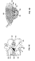
- FIGS. 1A and 1B illustrate a cross-sectional anatomical view of a vertebra and associated disc and a lateral view of a portion of a lumbar and thoracic spine, respectively. Structures of a typical cervical vertebra (superior aspect) are shown in FIG.
- 1A 104 - lamina; 106 - spinal cord; 108 - dorsal root of spinal nerve; 114 - ventral root of spinal nerve; 116 - posterior longitudinal ligament; 118 - intervertebral disc; 120 - nucleus pulposus; 122 - annulus fibrosus; 124 - anterior longitudinal ligament; 126 - vertebral body; 128 - pedicle; 130 - vertebral artery; 132 - vertebral veins; 134 - superior articular facet; 136 - posterior lateral portion of the annulus; 138 - posterior medial portion of the annulus; and 142 - spinous process.
- FIG. 1A 104 - lamina; 106 - spinal cord; 108 - dorsal root of spinal nerve; 114 - ventral root of spinal nerve; 116 - posterior longitudinal ligament; 118 - intervertebral disc; 120 - nucleus pulposus; 122 - annulus
- FIG. 1A is a lateral aspect of the lower portion of a typical spinal column showing the entire lumbar region and part of the thoracic region and displaying the following structures: 118 - intervertebral disc; 126 - vertebral body; 142 - spinous process; 170 - inferior vertebral notch; 172 - spinal nerve; 174 - superior articular process; 176 - lumbar curvature; and 180 - sacrum.
- FIG. 1D looks down on an instrument introduced by the posterior lateral approach.
- U.S. Patent No. 5,433,739 discloses placement of an RF electrode in an interior region of the disc approximately at the center of the disc. RF power is applied, and heat then putatively spreads out globally throughout the disc.
- the '739 patent teaches the use of a rigid shaft which includes a sharpened distal end that penetrates through the annulus fibrosus and into the nucleus pulposus.
- the shaft has to be rigid enough to permit the distal end of the RF electrode to pierce the annulus fibrosus, and the ability to maneuver its distal end within the nucleus pulposus is limited.
- a somewhat more flexible shaft is disclosed.
- neither embodiment of the devices of the '739 patent permits access to the posterior, posterior lateral and posterior medial region of the disc, nor do they provide for focal delivery of therapy to a selected local region within the disc or precise temperature control at the annulus.
- the '739 patent teaches the relief of pain by globally heating the disc. There is no disclosure of treating an annular tear or fissure.
- U.S. Patent No. 5,201,729 discloses the use of an optical fiber that is introduced into a nucleus pulposus.
- the distal end of a stiff optical fiber shaft extends in a lateral direction relative to a longitudinal axis of an introducer. This prevents delivery of coherent energy into the nucleus pulposus in the direction of the longitudinal axis of the introducer.
- the device of the '729 patent is unable to gain close proximity to selected portion(s) of the annulus (i.e., posterior, posterior medial and central posterior) requiring treatment or to precisely control the temperature at the annulus. No use in treating an annular fissure is disclosed.
- EP-A-0 682 910 discloses a tissue treatment instrument according to the first part of claim 1.
- the instrument has a guiding device with an outer positioning guided tube and a flexible guide tube contained within it.
- the flexible guided tube has a proximal end piece that can be bent by means of an actuation device and can be rotated by means of a rotating device.
- disc abnormalities such as disc degeneration at locations previously not accessible via percutaneous approaches and without major surgical intervention or substantial destruction to the disc.
- an externally guidable intervertebral disc treatment apparatus for treating disease in an intervertebral disc in need thereof, said intervertebral disc having a nucleus pulposus, an annulus fibrosus, and an inner wall of said annulus fibrosus, said nucleus pulposus having a first diameter in a disc plane between opposing sections of said inner wall of said annulus fibrosus, said externally guidable intervertebral disc treatment apparatus comprising:
- An embodiment of this invention can provide an intervertebral disc apparatus that includes an introducer with an introducer lumen and a catheter.
- the catheter can be at least partially positioned in the introducer lumen and includes an intradiscal section and an energy delivery device coupled to the intradiscal section.
- the intradiscal section can be configured to be advanceable through a nucleus pulposus of the intervertebral disc and positionable adjacent to a selected site of an inner wall of an annulus fibrosis.
- the energy delivery device can be configured to deliver sufficient energy to heat at least a portion of the intervertebral disc without substantially removing intervertebral disc material positioned adjacent to the energy delivery device.
- an externally guidable intervertebral disc apparatus for manipulation of disc tissue present at a preselected location of an intervertebral disc, the disc having a nucleus pulposus, an annulus fibrosis, and an inner wall of the annulus fibrosis, the nucleus pulposus having a first diameter and a disc playing between opposing sections of the inner wall, proximity to the nucleus being provided by an introducer comprising an internal introducer humen with an opening at a terminus of the introducer, comprising a catheter having a distal end and a proximal end having a longitudinal access, the catheter being adapted to slidably advance through the introducer lumen, the catheter having an intradiscal section at the distal end of the catheter, the intradiscal section being extendable through the opening of the introducer and having sufficient rigidity to be advanceable through the nucleus pulposus of the disc and around the inner wall of the annulus fibrosis under a force
- Embodiments of this invention are suitable for manipulating a disc tissue with a fissure or tear in an intervertebral disc, the disc having a nucleus pulposus and an annulus fibrosus, and the annulus having an inner wall of the annulus fibrosus.
- Embodiments of this invention are suitable for manipulating disc tissue at a preselected location of an intervertebral disc.
- Embodiments of this invention are suitable for treating an intervertebral fissure by placing an energy source adjacent to the fissure and providing sufficient energy to the fissure to raise the temperature to at least about 45-70°C and for a sufficient time to cause the collagen to weld.
- the present invention provides a method and apparatus for treating intervertebral disc disorders by the application of controlled heating to a localized region of an intervertebral disc.
- Such disorders include but are not limited to (i) degenerative discs which have tears or fissures in the annulus fibrosis, particularly fissures of the annulus fibrosis, which may or may not be accompanied with contained or escaped extrusions, (ii) contained disc herniations with focal protrusions, and (iii) bulging discs.
- Such disorders include but are not limited to (i) degenerative discs which have tears or fissures in the annulus fibrosis, (ii) contained disc herniations with focal protrusions, and (iii) bulging discs.
- Electromagnetic energy is delivered to a selected section of the disc in an amount which does not create a destructive lesion to the disc, other than at most a change in the water content of the nucleus pulposus. In one embodiment, there is no removal and/or vaporization of disc material positioned adjacent to an energy delivery device positioned in a nucleus pulposus. Sufficient electromechanical energy is delivered to the disc to change its biochemical, neurophysiologic and/or biomechanical properties. Neurophysiologic modifications include denervation of nociceptores in a tear or fissure in the annulus fibrosis.
- Degenerative intervertebral discs with fissures are treated by denervating selected nerves that are embedded in the interior wall of the annulus fibrosis as well as nerves outside of the interior wall including those on the surface of the wall. Electromagnetic energy is used to cauterize granulation tissue which are pain sensitive areas and formed in the annulus fibrosis wall. Electromagnetic energy is also used to break down selected enzyme systems and neurotransmitters that generate pain within the disc. Generally, these enzymes and neurotransmitters only work within a small bandwidth of both pH and temperature.
- Electromagnetic energy is applied to shrink collagen in the annulus fibrosis and/or nucleus pulposus. This reduces the redundancy in the disc roll that is created in a degenerative disc. Delivery of electromagnetic energy to the nucleus pulposis removes some water and permits the nucleus pulposis to withdraw. This reduces a "pushing out" effect that created a contained herniation. Combinations of shrinking the disc, shrinking of the nucleus pulposis by reducing water content, as well as tightening up the annulus fibrosis wall creates a rejuvenation of the disc. Reducing the pressure in the disc and tightening the annulus fibrosis produces a favorable biomechanical effect. Application of electromagnetic energy locally increases the stiffness of the disc.
- the annulus fibrosis is comprised primarily of fibrosis-like material and the nucleus pulposis is comprised primarily of an amorphous colloidal gel.
- the distinction between the annulus fibrosis and the nucleus pulposis becomes more difficult to distinguish when a patient is 30 years old or greater. There is often a transition zone between the annulus fibrosis and the nucleus pulposis made of fibrosis-like material and amorphous colloidal gel.
- the inner wall of the annulus fibrosis includes the young wall comprised primarily of fibrosis-like material as well as the transition zone which includes both fibrous-like material and amorphous colloidal gels (hereinafter collectively referred to as "inner wall of the annulus fibrosis").
- an apparatus of the invention is in the form of an externally guidable intervertebral disc apparatus for accessing and manipulating disc tissue present at a selected location of an intervertebral disc having a nucleus pulposus and an annulus fibrosus, the annulus having an inner wall.
- a temperature-controlled energy delivery element combined with the navigational control of the inventive catheter, provides preferential, localized heating to treat the fissure.
- the nucleus pulposus can be considered as having a given diameter in a disc plane between opposing sections of the inner wall. This nucleus pulposus diameter measurement allows instrument sizes (and parts of instruments) designed for one size disc to be readily converted to sizes suitable for an instrument designed for a different size of disc.
- the operational portion of the apparatus of the invention is brought to a location in or near the disc's fissure using techniques and apparatuses typical of percutaneous interventions.
- the term "introducer" is used to describe this aid to the method.
- An introducer has an internal introducer lumen with a distal opening at a terminus of the introducer to allow insertion (and manipulation) of the operational parts of the apparatus into (and in) the interior of a disc.
- the operational part of the apparatus comprises an elongated element referred to as a catheter, various parts of which are located by reference to a distal end and a proximal end at opposite ends of its longitudinal axis.
- the proximal end is the end closest to the external environment surrounding the body being operated upon (which may still be inside the body in some embodiments if the catheter is attached to a handle insertable into the introducer).
- the distal end of the catheter is intended to be located inside the disc under conditions of use.
- the catheter is not necessarily a traditional medical catheter (i.e., an elongate hollow tube for admission or removal of fluids from an internal body cavity) but is a defined term for the purposes of this specification.
- Catheter has been selected as the operant word to describe this part of the apparatus, as the inventive apparatus is a long, flexible tube which transmits energy and/or material from a location external to the body to a location internal to the disc being accessed upon, such as a collagen solution and heat to the annular fissure.
- material can be transported in the other direction to remove material from the disc, such as removing material by aspiration to decrease pressure which is keeping the fissure open and aggravating the symptoms due to the fissure.
- the catheter is adapted to slidably advance through the introducer lumen, the catheter having an intradiscal section at the distal end of the catheter, the intradiscal section being extendible through the distal opening at the terminus of the introducer into the disc.
- a typical distance of extension is at least one-half the diameter of the nucleus pulposus, preferably in the range of one-half to one and one-half times the circumference of the nucleus.
- the intradiscal portion of the catheter is manufactured with sufficient rigidity to avoid collapsing upon itself while being advanced through the nucleus pulposus and navigated around the inner wall of the annulus fibrosus.
- the intradiscal portion has insufficient rigidity to puncture the annulus fibrosus under the same force used to advance the catheter through the nucleus pulposus and around the inner wall of the annulus fibrosus.
- Absolute penetration ability will vary with sharpness and stiffness of the tip of the catheter, but in all cases a catheter of the present invention will advance more readily through the nucleus pulposus than through the annulus fibrosus.
- the intradiscal section of the catheter further has differential bending ability in two orthogonal directions at right angles to the longitudinal axis. This causes the catheter to bend along a desired plane (instead of at random). Also when a torsional (twisting) force is applied to the proximal end of the catheter to re-orient the distal end of the catheter, controlled advancement of the catheter in the desired plane is possible.
- a further component of the catheter is a functional element located in the intradiscal section for diagnosis or for adding energy and adding and/or removing material at the selected location of the disc where the annular tear is to be treated.
- the apparatus allows the functional element to be controllably guided by manipulation of the proximal end of the catheter into a selected location for localized treatment of the annular fissure.
- the method of the invention which involves manipulating disc tissue at the annular fissure, is easily carried out with an apparatus of the invention.
- An introducer is provided that is located in a patient's body so that its proximal end is external to the body and the distal opening of its lumen is internal to the body and (1) internal to the annulus fibrosus or (2) adjacent to an annular opening leading to the nucleus pulposus, such as an annular tear or trocar puncture that communicates with the nucleus pulposus.
- the catheter is then slid into position in and through the introducer lumen so that the functional element in the catheter is positioned at the selected location of the disc by advancing or retracting the catheter in the introducer lumen and optionally twisting the proximal end of the catheter to precisely navigate the catheter.
- the distal portion of the catheter will curve along the inner wall of the annulus fibrosus as it is navigated and is selectively guided to an annular tear at selected location(s) in the disc. Energy is applied and/or material is added or removed at the selected location of the disc via the functional element.
- the annulus fibrosus is comprised primarily of tough fibrous material, while the nucleus pulposus is comprised primarily of an amorphous colloidal gel. There is a transition zone between the annulus fibrosus and the nucleus pulposus made of both fibrous-like material and amorphous colloidal gel. The border between the annulus fibrosus and the nucleus pulposus becomes more difficult to distinguish as a patient ages, due to degenerative changes. This process may begin as early as 30 years of age.
- the inner wall of the annulus fibrosus can include the young wall comprised primarily of fibrous material as well as the transition zone which includes both fibrous material and amorphous colloidal gels (hereafter collectively referred to as the "inner wall of the annulus fibrosus"). Functionally, that location at which there is an increase in resistance to catheter penetration and which is sufficient to cause bending of the distal portion of the catheter into a radius less than that of the internal wall of the annulus fibrosus is considered to be the "inner wall of the annulus fibrosus.”
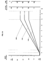
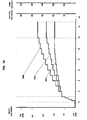
- stages 1-5 degenerative disc disease
- Adams et al. "The Stages of Disc Degeneration as Revealed by Discograms," J. Bone and Joint Surgery, 68 , 36-41 (1986).
- the methods of instrument navigation described herein would probably not be able to distinguish between the nucleus and the annulus in degenerative disease of grade 5.
- most treatment is expected to be performed in discs in stages 3 and 4, as stages 1 and 2 are asymptomatic in most patients, and stage 5 may require disc removal and fusion.
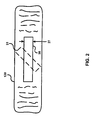
- a disc plane 30 of the intervertebral disc is generally a plane of some thickness 27 within the nucleus pulposus 120 orthogonal to the axis formed by the spinal column (i.e., such a disc plane is substantially horizontal in a standing human, corresponding to the "flat" surface of a vertebra).
- a oblique plane 31 extends along any tilted orientation relative to axial plane 30; however, when the plane is tilted 90°, such a plane would be substantially vertical in a standing human and is referred to as a cephalo-caudal plane. Reference is made to such planes to describe catheter movements with respect to the disc plane.
- disc plane 30 has a thickness no greater than the thickness of the intervertebral disc, preferably a thickness no greater than 75% of a thickness of the intervertebral disc, and more preferably a thickness no greater than 50% of a thickness of the intervertebral disc.
- Movement of the intradiscal portion 16 of catheter 14 is confined within a disc plane by the physical and mechanical properties of the intradiscal portion 16 during advancement of the catheter when the bending plane of the catheter is aligned with the disc plane, until some additional force is applied to the catheter by the physician.
- a twisting force (which can be applied mechanically, electrically, or by any other means) acting on the proximal end of the catheter changes the forces acting on the distal end of the catheter so that the plane of the catheter bend can be angled relative to the disc plane as the catheter is advanced.
- the physician can cause the distal end of the catheter to move up or down, depending on the direction of the twist.
- a device of the invention can be prepared in a number of different forms and can consist (for example) of a single instrument with multiple internal parts or a series of instruments that can be replaceably and sequentially inserted into a hollow fixed instrument (such as a needle) that guides the operational instruments to a selected location in or adjacent to an annular fissure.
- a hollow fixed instrument such as a needle
- the present invention is directed to navigation of an instrument through the nucleus pulposus, particularly to the moveable distal portion of the probe, and not to the instrument or instruments used to access the nucleus pulposus, the general term "introducer" is used to refer to the instrument that provides access to the nucleus.
- the form of the introducer is not a material part of the present invention and can vary.
- the introducer in its simplest form, can consist of a hollow needle-like device (optionally fitted with an internal removable obturator or trocar to prevent clogging during initial insertion, variously known as a stylet, obturator, or trocar, depending on its shape and other functions) or a combination of a simple exterior cannula that fits around a trocar.
- a hollow tube the needle or exterior cannula after removal of the obturator or trocar, respectively
- the hollow introducer acts as a guide for introducing instrumentation.
- obturator any instrument that acts to seal off the interior of the body from the external environment after withdrawal of the trocar.
- obturators are well known in the art.
- a particularly preferred introducer is a 17- or 18-gauge, thin-wall needle with a matched obturator, which after insertion is replaced with a catheter of the present invention.
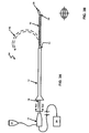
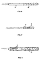
- FIGS. 3A and 3B illustrate one embodiment of a catheter 14 of the invention as it would appear inserted into an introducer 12.
- the apparatus shown is not to scale, as an exemplary apparatus (as will be clear from the device dimensions below) would be relatively longer and thinner; the proportions used in FIG. 3A were selected for easier viewing by the reader.
- the distal portion of an intervertebral apparatus operates inside an introducer 12 having an internal introducer lumen 13.
- a flexible, movable catheter 14 is at least partially positionable in the introducer lumen 13.
- Catheter 14 includes a distal end section 16 referred to as the intradiscal section, which is designed to be the portion of the catheter that will be pushed out of the introducer lumen and into the nucleus pulposus, where movement of the catheter will be controlled to bring operational portions of the catheter into the selected location(s) with regard to the annular tear.
- the intradiscal section is designed to be the portion of the catheter that will be pushed out of the introducer lumen and into the nucleus pulposus, where movement of the catheter will be controlled to bring operational portions of the catheter into the selected location(s) with regard to the annular tear.
- dashed lines are used to illustrate bending of the intradiscal portion of the catheter as it might appear under use, as discussed in detail later in the specification.
- FIG. 3B shows an end view of handle 11 at the proximal end of the catheter, with the handle 11 having an oval shape to indicate the plane of bending, also discussed in detail later in the specification. Other sections and properties of catheter 14 are described later.
- the outer diameter of catheter 14 is in the range of 0.2 to 5 mm
- the total length of catheter 14 (including the portion inside the introducer) is in the range of 10 to 60 cm
- the length of introducer 12 is in the range of 5 to 50 cm.
- the catheter has a diameter of 1 mm, an overall length of 30 cm, and an introduced length of 15 cm (for the intradiscal section). With an instrument of this size, a physician can insert the catheter for a distance sufficient to reach selected location(s) in the nucleus of a human intervertebral disc
- FIG. 4 illustrates the anatomy of an intervertebral disc and shows an apparatus of the invention inserted into a disc. Structures of the disc are identified and described by these anatomical designations: the posterior lateral inner annulus 136, posterior medial inner annulus 138, annulus fibrosus 122/nucleus pulposus 120 interface, the annulus/dural interface 146, annulus/posterior longitudinal ligament interface 148, anterior lateral inner annulus 150, and the anterior medial inner annulus 152.
- the mechanical characteristics of intradiscal section 16 of catheter 14 are selected to have (1) sufficient column strength along the longitudinal axis of the catheter to avoid collapse of the catheter and (2) different flexural strengths along the two axes orthogonal to the longitudinal axis to allow controlled bending of the catheter. These parameters make the catheter conformable and guidable along inner wall 22 of an annulus fibrosus 122 to reach selected location(s), such as the posterior medial annulus 138.
- the necessary design features can be selected (in an interrelated fashion) by first providing the intradiscal section of the catheter with sufficient column strength to be advanceable through normal human nucleus pulposus and around the inner wall of the annulus fibrosus without collapse.
- column strength refers to bending sufficient to inhibit further advancement at the tip. Advancement of the tip is restricted by 1) sliding through the normal gelatinous nucleus pulposus, 2) contacting denser clumps of nucleus pulposus, and 3) curving and advancing along the inner wall of the annulus.
- Column strength can be increased in many ways known in the art, including but not limited to selecting materials (e.g., metal alloy or plastic) with a high resistance to bending from which to form the catheter, forming the structure of the catheter with elements that add stiffening (such as bracing), and increasing the thickness of the structural materials. Column strength can be decreased to favor bending by selecting the opposite characteristics (e.g., soft alloys, hinging, and thin structural elements).
- selecting materials e.g., metal alloy or plastic
- elements that add stiffening such as bracing
- Column strength can be decreased to favor bending by selecting the opposite characteristics (e.g., soft alloys, hinging, and thin structural elements).
- the catheter When the catheter collapses, the physician feels an abrupt decrease in resistance. At that time, the catheter forms one or more loops or kinks between the tip of the introducer and the distal tip of the catheter.
- the tip 28 of intradiscal section 16 is biased or otherwise manufactured so that it forms a pre-bent segment prior to contact with the annulus fibrosus as shown in FIG. 3A.
- the bent tip will cause the intradiscal section to tend to continue to bend the catheter in the same direction as the catheter is advanced.
- This enhanced curving of a pre-bent catheter is preferred for a catheter that is designed to reach a posterior region of the nucleus pulposus; however, such a catheter must have sufficient column strength to prevent the catheter from collapsing back on itself
- the intradiscal section not only must allow bending around the relatively stronger annulus fibrosus in one direction, but also resist bending in the orthogonal direction to the plane in which bending is designed to occur.
- the bending stiffness of the intradiscal section as measured in Taber stiffness units should be in the range of 2-400 units (in a 0-10,000 unit range) in the desired bending plane, preferably 3-150 units. In preferred embodiments, stiffness is in the range of 4-30 units in the desired bending plane. In all cases, the bending stiffness preferably is 2-20 times higher for bending in the orthogonal direction.
- the column or compressive strength of the intradiscal section (force required to buckle a segment whose length is 25 times its diameter) is in the range of 0.05 to 4 kg, preferably 0.05 to 2 kg. In the most preferred embodiments, it is in the range of 0.1 to 1 kg. In the proximal shaft section (i.e., the part of the catheter proximal to the intradiscal section), this strength is in the range of 0.1 to 25 kg, preferably 0.2 to 7 kg. In the most preferred embodiments, it is in the range of 0.7 to 4 kg.
- intradiscal section 16 is guidable and can reach the posterior, the posterior lateral, and the posterior medial regions of the posterior wall of the annulus fibrosus, as well as other selected section(s) on or adjacent to inner wall 22.
- intradiscal section 16 is first positioned in the nucleus pulposus 120 by means of the introducer.
- introducer 12 pierces annulus fibrosus 122 and is advanced through the wall of the annulus fibrosus into the nucleus pulposus. In such embodiments, introducer 12 is then extended a desired distance into nucleus pulposus 120. Catheter 14 is advanced through a distal end of introducer 12 into nucleus pulposus 120. Advancement of the catheter 14, combined with increased resistance to advancement at the annulus fibrosus, causes the tip of the intradiscal section to bend relative to the longitudinal axis of introducer 12 when the intradiscal section contacts the inner wall of the annulus fibrosus 122.
- Catheter 14 is navigated along inner wall 22 of annulus fibrosus 122 to selected site(s) of inner wall 22 or within nucleus pulposus 120.
- intradiscal section 16 can be positioned in or adjacent to a fissure or tear 44 of annulus fibrosus 122.
- the distal portion 28 of intradiscal section 16 is designed to be incapable of piercing the annulus fibrosus 122.
- the inability of distal portion 28 to pierce the annulus can be the result of either shape of the tip 29 or flexibility of distal portion 28, or both.
- the tip 29 is considered sufficiently blunt when it does not penetrate the annulus fibrosus but is deflected back into the nucleus pulposus or to the side around the inner wall of the when the tip 29 is advanced.
- the tip can be made with a freely rotating ball. This embodiment provides not only a blunt surface but also a rolling contact to facilitate navigation.
- an introducer 12 pierces the skin and reaches an exterior of annulus fibrosus 122.
- a rigid and sharp trocar is then advanced through introducer 12, to pierce annulus fibrosus 122 and enter the disc.
- the trocar is then removed, and catheter 14 is advanced through a distal end of introducer 12, following the path created by the trocar in annulus fibrosus 122 beyond the end of the introducer.
- the introducer is outside the annulus fibrosus 122 and only the catheter with its guidable distal portion 16 is present inside the disc.
- the physician can manipulate the proximal portion 15 of the catheter to move the distal portion of the catheter to a selected location for treating a fissure of the annulus fibrosus 122.
- Catheter 14 is not always pre-bent as shown in FIG. 3A, but optionally can include a biased distal portion 28 if desired.
- Pre-bent or “biased” means that a portion of the catheter (or other structural element under discussion) is made of a spring-like material that is bent in the absence of external stress but which, under selected stress conditions (for example, while the catheter is inside the introducer), is linear.
- Such a biased distal portion can be manufactured from either spring metal or superelastic memory material (such as Tinel® nickel-titanium alloy, Raychem Corp., Menlo Park CA).
- the introducer (at least in the case of a spring-like material for forming the catheter) is sufficiently strong to resist the bending action of the bent tip and maintain the biased distal portion in alignment as it passes through the introducer.
- a catheter with a biased distal portion 28 encourages advancement of intradiscal section 16 substantially in the direction of the bend relative to other lateral directions as shown by the bent location of intradiscal section 16 indicated by dashed lines in FIG. 3A. Biasing the catheter tip also further decreases likelihood that the tip 29 will be forced through the annulus fibrosus under the pressure used to advance the catheter.
- a catheter tip In addition to biasing a catheter tip prior to insertion into an introducer, a catheter tip can be provided that is deflected by mechanical means, such as a wire attached to one side of the tip that deflects the tip in the desired direction upon application of force to the proximal end of the deflection wire.
- mechanical means such as a wire attached to one side of the tip that deflects the tip in the desired direction upon application of force to the proximal end of the deflection wire.
- Any device in which bending of the tip of a catheter of the invention is controlled by the physician is “actively steerable.”
- other methods of providing a bending force at the tip can be used, such as hydraulic pressure and electromagnetic force (such as heating a shaped memory alloy to cause it to contract). Any of a number of techniques can be used to provide selective bending of the catheter in one lateral direction.
- a guiding mandrel 32 can be included both to add rigidity to the catheter and to inhibit movement of catheter 14 in the inferior and superior directions while positioned and aligned in the disc plane of a nucleus pulposus 120. This aids the functions of preventing undesired contact with a vertebra and facilitating navigation.
- the mandrel can be flattened to encourage bending in a plane (the "plane of the bend") orthogonal to the "flat" side of the mandrel.
- "Flat" here is a relative term, as the mandrel can have a D-shaped cross-section, or even an oval or other cross-sectional shape without a planar face on any part of the structure.
- the minimum ratio is 1.25:1 ("thickest" to "thinnest" cross-sectional dimensions along at least a portion of the intradiscal section).
- the maximum ratio is 20:1, with the preferred ratio being between 1.5:1 and 16:3, more preferably between 2:1 and 3.5: 1.
- a catheter of the present invention is designed with sufficient torsional strength (resistance to twisting) to prevent undesired directional movement of the catheter.
- Mandrels formed from materials having tensile strengths in the range set forth in the examples of this specification provide a portion of the desired torsional strength. Other materials can be substituted so long as they provide the operational functions described in the examples and desired operating parameters.
- mandrel can provide a significant portion of the column strength, selective flexibility, and torsional strength of a catheter
- other structural elements of the catheter also contribute to these characteristics. Accordingly, it must be kept in mind that it is the characteristics of the overall catheter that determine suitability of a particular catheter for use in the methods of the invention.
- a mandrel that does not have sufficient torsional strength when acting alone can be combined with another element, such as anti-twisting outer sheath 40 or inserting/advancing a second mandrel, to provide a catheter of the invention.
- components inside the catheter such as a heating element or potting compound, can be used to strengthen the catheter or provide directional flexibility at the locations of these elements along the catheter.
- the guiding mandrel 32 be flattened along its entire length. Different mandrels can be designed for different sized discs, both because of variations in disc sizes from individual to individual and because of variations in size from disc to disc in one patient.
- the bendable portion of the mandrel is preferably sufficient to allow intradiscal portion 16 of the catheter to navigate at least partially around the circumference of the inner wall of the annulus fibrosus (so that the operational functions of the catheter can be carried out at desired location(s) along the inner wall of the annulus fibrosus). Shorter bendable sections are acceptable for specialized instruments. In most cases, a flattened distal portion of the mandrel of at least 10 mm, preferably 25 mm, is satisfactory. The flattened portion can extend as much as the entire length of the mandrel, with some embodiments being flattened for less than 15 cm, in other cases for less than 10 cm, of the distal end of the guide mandrel.
- the guide mandrel or other differential bending control element is maintained in a readily determinable orientation by a control element located at the proximal end of the catheter.
- the orientation of the direction of bending and its amount can be readily observed and controlled by the physician.
- One possible control element is simply a portion of the mandrel that extends out of the proximal end of the introducer and can be grasped by the physician, with a shape being provided that enables the physician to determine the orientation of the distal portion by orientation of the portion in the hand.
- a flattened shape can be provided that mimics the shape at the distal end (optionally made larger to allow better control in the gloved hand of the physician, as in the handle 11 of FIG. 3B).
- More complex proximal control elements capable of grasping the proximal end of the mandrel or other bending control element can be used if desired, including but not limited to electronic, mechanical, and hydraulic controls for actuation by the physician.
- the guide mandrel can also provide the function of differential flexibility by varying the thickness in one or more dimensions (for example, the "thin” dimension, the “thick” dimension, or both) along the length of the mandrel.
- a guide mandrel that tapers (becomes gradually thinner) toward the distal tip of the mandrel will be more flexible and easier to bend at the tip than it is at other locations along the mandrel.
- a guide mandrel that has a thicker or more rounded tip than more proximal portions of the mandrel will resist bending at the tip but aid bending at more proximal locations. Thickening (or thinning) can also occur in other locations along the mandrel.
- Control of the direction of bending can be accomplished by making the mandrel more round, i.e., closer to having I : 1 diameter ratios; flatter in different sections of the mandrel; or by varying the absolute dimensions (increasing or decreasing the diameter).
- Such control over flexibility allows instruments to be designed that minimize bending in some desired locations (such as the location of connector of an electrical element to avoid disruption of the connection) while encouraging bending in other locations (e.g., between sensitive functional elements).
- a catheter that is uniformly flexible along its entire length is variably flexibility along its entire length, or has alternating more flexible and less flexible segment(s), is readily obtained simply by manufacturing the guide mandrel with appropriate thickness at different distances and in different orientations along the length of the mandrel.
- Such a catheter will have two or more different radii of curvature in different segments of the catheter under the same bending force.
- the most distal 3 to 40 mm of a guide mandrel is thinner relative to central portions of the intradiscal section to provide greater flexibility, with the proximal 10 to 40 mm of the intradiscal section being thicker and less flexible to add column strength and facilitate navigation.
- the actual dimensions of the guide mandrel will vary with the stiffness and tensile strength of the material used to form the mandrel.
- the mandrel will be formed from a metal (elemental or an alloy) or plastic that will be selected so that the resulting catheter will have characteristics of stiffness and bending that fall within the stated limits. Additional examples of ways to vary the stiffness and tensile strength include transverse breaks in a material, advance of the material so that it "doubles up,” additional layers of the same or different material, tensioning or relaxing tension on the catheter, and applying electricity to a memory metal.
- guiding mandrel is combined with at least a portion of the catheter 14 to form a structure which provides the functions of both, a wall/mandrel 41.
- the wall/mandrel 41 of catheter 14 can be varied in dimensions as described in the previous section of this specification directed to a separate mandrel, with the same resulting changes in function.
- changing the thickness of the wall/mandrel 41 that functions as the mandrel portion changes the flexibility and preferred direction of bending of the catheter.
- the wall/mandrel 41 will be thinner than other portions of the catheter wall 33 so that wall/mandrel 41 controls bending.
- wall/mandrel 41 can be formed of a different material than the other portions 33 of the catheter walls (i.e., one with a lower tensile and/or flexural strength) in order to facilitate bending.
- thermal energy delivery device lumen 34 can receive any of a variety of different couplings from an energy source 20 to a thermal energy delivery device (functional element) further along the catheter, including but not limited to a wire or other connector between thermal energy elements.
- hollow lumen(s) 36 for delivery or removal of a fluid or solid connectors for application of a force to a mechanical element can be present, so no limitation should be placed on the types of energy, force, or material transporting elements present in the catheter.
- the purpose of the inventive catheter is to repair tears or fissures in a disc by operation of the instrument at the tear location adjacent to or inside the disc, a functional element is provided in or on the catheter to carry out that purpose.
- Non-limiting examples of functional elements include any element capable of aiding diagnosis, delivering energy, or delivering or removing a material from a location adjacent the element's location in the catheter, such as an opening in the catheter for delivery of a fluid (e.g., dissolved collagen to seal the fissure) or for suction, a thermal energy delivery device (heat source), a mechanical grasping tool for removing or depositing a solid, a cutting tool (which includes all similar operations, such as puncturing), a sensor for measurement of a function (such as electrical resistance, temperature, or mechanical strength), or a functional element having a combination of these functions.
- a fluid e.g., dissolved collagen to seal the fissure
- a thermal energy delivery device heat source
- a mechanical grasping tool for removing or depositing a solid
- a cutting tool which includes all similar operations, such as puncturing
- a sensor for measurement of a function such as electrical resistance, temperature, or mechanical strength
- the functional element can be at varied locations in the intradiscal portion of the catheter, depending on its intended use. Multiple functional elements can be present, such as multiple functional elements of different types (e.g., a heat source and a temperature sensor) or multiple functional elements of the same type (e.g., multiple heat sources spaced along the intradiscal portion).
- multiple functional elements of different types e.g., a heat source and a temperature sensor
- multiple functional elements of the same type e.g., multiple heat sources spaced along the intradiscal portion.
- thermal energy delivery device 18 One of the possible functional elements present on intradiscal section 16 is a thermal energy delivery device 18.
- thermal energy delivery device 18 A variety of different types of thermal energy can be delivered including but not limited to resistive heat, radio frequency (RF), coherent and incoherent light, microwave, ultrasound and liquid thermal jet energies.
- thermal energy delivery device 18 is positioned proximal to the distal portion of intradiscal section 16 so that there is no substantial delivery of energy at the distal portion, which can then perform other functions without being constrained by being required to provide energy (or resist the resulting heat).
- Infusion lumen 36 is configured to transport a variety of different mediums including but not limited to electrolytic solutions (such as normal saline), contrast media (such as Conray meglumine iothalamate), pharmaceutical agents, disinfectants, filling or binding materials such as collagens or cements, chemonucleolytic agents and the like, from a reservoir exterior to the patient to a desired location within the interior of a disc (i.e., the fissure).
- electrolytic solutions such as normal saline
- contrast media such as Conray meglumine iothalamate
- pharmaceutical agents such as disinfectants, filling or binding materials such as collagens or cements, chemonucleolytic agents and the like
- infusion lumen 36 can be used as an aspiration lumen to remove nucleus material or excess liquid or gas (naturally present, present as the result of a liquefying operation, or present because of prior introduction) from the interior of a disc.
- the infusion lumen is sometimes referred to as an irrigation lumen.
- Infusion lumen 36 can be coupled to medium reservoir 21 through the catheter (see FIG. 3B).
- sensor lumens 42 Included in the particular embodiment shown in this figure is one or more sensor lumens 42.
- An example is a wire connecting a thermal sensor at a distal portion of the catheter to control elements attached to a connector in the proximal handle 11 of the catheter.
- an optional energy directing device 43 including but not limited to a thermal reflector, an optical reflector, thermal insulator, or electrical insulator.
- Energy directing device 43 is configured to limit thermal and/or electromagnetic energy delivery to a selected site of the disc and to leave other sections of the disc substantially unaffected.
- Energy directing device 43 can be positioned on an exterior surface of catheter intradiscal section 16 and/or catheter 14 as well as in an internal portion of the catheter intradiscal section 16 and/or catheter 14. For example, the energy can be directed to the walls of the fissure to cauterize granulation tissue and to shrink the collagen component of the annulus, while the nucleus is shielded from excess heat.
- catheter intradiscal section 16 and/or distal portion 28 are positionable to selected site(s) around and/or adjacent to inner wall 22 of annulus fibrosus 122 for the delivery of therapeutic and/or diagnostic agents including but not limited to, electromagnetic energy, electrolytic solutions, contrast media, pharmaceutical agents, disinfectants, collagens, cements, chemonucleolytic agents and thermal energy.
- Intradiscal section 16 is navigational and can reach the posterior, the posterior lateral, the posterior medial, anterior lateral, and anterior medial regions of the annulus fibrosus, as well as selected section(s) on or adjacent to inner wall 22.
- intradiscal section 16 is positioned along the posterior lateral wall of the intervertebral disc, along the anterior lateral wall of the intervertebral disc, or along the anterior medial wall of the intervertebral disc, as it is steerable and can be positioned at any of the above-mentioned sites. In a preferred embodiment, intradiscal section 16 is positioned adjacent to the entire posterior wall of the disc. Sufficient thermal energy can then be delivered, for example, to selectively heat the posterior annulus to cauterize granulation tissue and shrink the collagen component of the wall around and adjacent to fissure 44 without undue damage to other portions of the intervertebral disc, particularly the nucleus. These actions help close the fissure in the annulus.
- intradiscal section 16 and/or distal portion 28 delivers electromagnetic energy to heat tissue and thereby reduce pain at a selected site, (e.g., to any portion of annulus fibrosis 122), especially along the posterior wall of the annulus fibrosis.
- a selected site e.g., to any portion of annulus fibrosis 122
- intradiscal section 16 and/or distal portion 28 delivers thermal energy to reduce pain at a selected site (e.g., any portion of annulus fibrosis 122), without ablation or removal of any disc material adjacent to intradiscal section 16 of catheter 14 and with or without removal of water vapor from the disc but without charring the nucleus.
- Intradiscal section 16 also can heat the collagen components of the annulus, thereby shrinking the annulus, with or without desiccating local tissue.
- intradiscal section 16 and/or distal portion 28 delivers RF energy to reduce pain at a selected site (e.g., to any portion of annulus fibrosis 24 and/or nucleus pulposis 26), especially along the posterior wall of the annulus fibrosis.
- a selected site e.g., to any portion of annulus fibrosis 24 and/or nucleus pulposis 26
- markings 38 are visible on the portion of the catheter that is located during normal operation outside the body being acted upon, particularly for embodiments in which the proximal end of the catheter is designed to be directly manipulated by the hand of the physician. Advancement of the catheter into the introducer will advance the markings into the introducer, thereby showing how far the catheter has been advanced into the nucleus.
- a visible marking 38 can be positioned on an exterior surface of the catheter or can be present on an interior surface and visible through a transparent outer covering or sheath. Preferred are visible markings every centimeter to aid the physician in estimating the catheter tip advancement.
- visible markings can also be used to show twisting motions of the catheter to indicate the orientation of the bending plane of the distal portion of the catheter. It is preferred, however, to indicate the distal bending plane by the shape and feel of the proximal end of the catheter assembly.
- the catheter can be attached to or shaped into a handle 11 that fits the hand of the physician and also indicates the orientation of the distal bending plane. Both the markings and the handle shape thus act as control elements to provide control over the orientation of the bending plane; other control elements, such as plungers or buttons that act on mechanical, hydrostatic, electrical, or other types of controls, can be present in more complex embodiments of the invention.
- a radiographically opaque marking device can be included in the distal portion of the catheter (such as in the tip or at spaced locations throughout the intradiscal portion) so that advancement and positioning of the intradiscal section can be directly observed by radiographic imaging.
- radiographically opaque markings are preferred when the intradiscal section is not clearly visible by radiographic imaging, such as when the majority of the catheter is made of plastic instead of metal.
- a radiographically opaque marking can be any of the known (or newly discovered) materials or devices with significant opacity.
- Examples include but are not limited to a steel mandrel sufficiently thick to be visible on fluoroscopy, a tantalum/polyurethane tip, a gold-plated tip, bands of platinum, stainless steel or gold, soldered spots of gold and polymeric materials with radiographically opaque filler such as barium sulfate.
- a resistive heating element or an RF electrode(s) may provide sufficient radio-opacity in some embodiments to serve as a marking device.
- a sheath 40 can optionally be positioned around catheter 14.
- Sheath 40 provides a flexible surface that is smooth and provides for easy introduction into a selected area within the disc.
- Sheath 40 can be made of a variety of different materials including but not limited to polyester, rayon, polyimide, polyurethane, polyethylene, polyamide and silicone. When visible markings are present to indicate the advancement of the catheter, either the sheath carries the markings, or the sheath is clear to reveal markings underneath.
- thermal energy delivery device 18 is a resistive heating device.
- the thermal energy delivery device 18 can be a band or a coil.
- a heating coil 46 is positioned around an exterior of catheter 14.
- the heating element 46 need not be in the shape of a coil.
- the heating element can be in the form of a thin flexible circuit which is mountable on or in substantially one side of the intradiscal portion of the catheter.
- Heating element 46 is powered by a direct current source 20 (and less preferably a source of alternating current).
- Heating element is made of a material that acts as a resistor. Suitable materials include but are not limited to stainless steel, nickel/chrome alloys, platinum, and the like.
- the heating element is inside the intradiscal section of catheter 14 (FIG. 8).
- the resistive material is electrically insulated and substantially no current escapes into the body. With increasing levels of current, element 46 heats to greater temperature levels. Additionally, a circuit can be completed substantially entirely at intradiscal section 16 and a controllable delivery of thermal energy is achieved. In one embodiment, 2 watts pass through heating element 46 to produce a temperature of about 55°C in a selected target such as fissure 44, 3 watts produces 65°C, 4 watts produces 75°C, and so on
- thermal energy delivery device 18 is a radio frequency electrode, such as a band or coil.
- RF electrode 46 is positioned on an exterior of catheter 14.
- RF electrode 46 is powered by an RF generator.
- the electrode is made of suitable materials including but not limited to stainless steel or platinum.
- the RF electrode is located on intradiscal section of catheter 14. Increasing levels of current conducted into disc tissue heat that tissue to greater temperature levels.
- a circuit can be completed substantially entirely at intradiscal section 16 (bipolar device) or by use of a second electrode attached to another portion of the patient's body (monopolar device). In either case, a controllable delivery of RF energy is achieved.
- sufficient energy is delivered to the intervertebral disc to heat and shrink the collagen component of the annulus but not ablate tissue adjacent to catheter 14.
- the amount of thermal energy delivered to the tissue is a function of (i) the amount of current passing through heating element 46, (ii) the length, shape, and/or size of heating element 46, (iii) the resistive properties of heating j element 46, (iv) the gauge of heating element 46, and (v) the use of cooling fluid to control temperature. All of these factors can be varied individually or in combination to provide the desired level of heat.
- Power supply 20 associated with heating element 46 may be battery based.
- Catheter 14 can be sterilized and may be disposable.
- a thermal sensor 48 may be positioned in an interior location of catheter 14. In another embodiment, thermal sensor 48 is positioned on an exterior surface of catheter 14. A thermal sensor can be used to control the delivery of energy to thermal energy delivery device 18. A potting material can be used to fix the position of thermal sensor 48 and provide a larger area from which to average the measured temperature. Thermal sensor 48 is of conventional design, including but not limited to a thermistor; T type thermocouple with a copper-constantan junction; J type, E type, and K type thermocouples; fiber optics; resistive wires; IR detectors; and the like. Optionally, there may be a lumen 42 for the thermal sensor connection.
- sheath 40 may be used to cover resistive heating element 46.
- a plurality of resistive heating elements 46 can be used (FIG. 9) in a catheter of the invention.
- thermal energy delivery device 18 comprises one or more resistive heating elements 46 coupled to a resistive heating energy source.
- Resistive heating elements 46 are positioned along intradiscal section 16 at locations where they controllably deliver thermal energy to selected structures, including granulation tissue in a fissure 44 and the annulus surrounding the fissure. Resistive heating elements 46 can be segmented and multiplexed so that only certain resistive heating elements, or combinations of resistive heating elements, are activated at any one particular time.
- Thermal sensor 48 can be positioned between resistive heating elements 46 and/or at an exterior or interior location of catheter 14. In the embodiment illustrated in FIG. 10, catheter 14 can be prepared with a wound helical structural element 42 to increase flexibility and minimize kinking.
- multiple, spaced-apart structural elements 46 are shown which could have (for example) ports through which a material is delivered.
- catheter 14 including but not limited to a substantially smooth surface (and specifically including the devices using an internal guide mandrel as previously described).
- a sheath can be provided over the heating element, and the guiding mandrel inside the coil can be encapsulated in silicone potting material. The tubing flexibility and the silicone potting material prevent kinking.
- sheath 40 can be positioned around catheter 14 and also around resistive heating elements 46 to afford a substantially smooth surface. Resistive heating elements 46 can be at least partially covered by a thermally insulating material, for example, along one side of the catheter, to selectively heat disc tissue on the opposite side.
- One electrode occupies a portion of the side of the distal end and the other electrode is the distal-most tip of the RF probe.
- the electrodes are operated independently to provide different tissue temperatures.
- the side electrode has a smaller area than the end electrode. If the side electrode receives the same power as the end electrode, it will provide more concentrated current and thus will produce more thermal energy (within a given unit volume). The end electrode will provide gentler, less concentrated current and will produce less thermal energy (within a given unit volume), for example, to shrink collagen in the annulus without denaturing said collagen.
- thermal energy delivery device 18 is a resistive heating element 46. It will be appreciated that the embodiments illustrated in FIGS. 10 and 11 are readily adaptable to other thermal energy delivery sources (e.g., for radio frequency energy, the resistive heating element is replaced with insulated RF probe(s) and the energy source is an RF generator).
- the temperature of the tissue or of element 46 (FIG. 10) is monitored by sensors 48, and the output power of energy source 20 adjusted accordingly.
- the physician can, if desired, override control system 52.
- a microprocessor can be included and incorporated in the closed or open loop system to switch power on and off, as well as to modulate the power.
- the closed loop system utilizes a microprocessor to serve as a controller 54 which acts to monitor the temperature and adjust the power accordingly.
- Alternatives to the microprocessor are, for example, analog control circuitry and a logic controller.
- a tissue adjacent to resistive heating elements 46 can be maintained at a desired temperature for a selected period of time without aberrant high temperature fluctuations.
- Each resistive heating element 46 can be connected to separate control and power supply resources, which generate an independent output for each resistive heating element 46.
- a desired thermal output can be achieved by maintaining a selected energy at resistive heating elements 46 for a selected length of time.
- resistive heating element 46 When a resistive heating element 46 is used, current delivered through resistive heating element 46 can be measured by current sensor 56. Alternatively, when an RF electrode is used, the current delivered through the electrode can also be measured by the current sensor 56. Voltage can be measured by voltage sensor 58. Resistance and power are then calculated at power calculation device 60. These values can then be displayed at user interface and display 62. Signals representative of power and resistance values are received by a controller 54.
- a control signal is generated by controller 54 that is related to the current and voltages.
- the control signal is used by power circuits 66 to adjust the power output in an appropriate amount in order to maintain the desired temperature delivered at respective resistive heating elements 46.
- temperatures detected at sensors 48 provide feedback for maintaining a selected power.
- the actual temperatures are measured at temperature measurement device 68, and the temperatures are displayed at user interface and display 62.
- a control signal is generated by controller 54 that is related to the actually measured temperature and a desired temperature.
- the control signal is used by power circuits 66 to adjust the power output in an appropriate amount in order to maintain the desired temperature delivered at the respective sensor 48.
- a multiplexer can be included to measure current, voltage, and temperature at the sensors 48, 56 and 58, so that appropriate energy can be delivered to resistive heating elements 46.
- Controller 54 can be a digital or analog controller or a computer with software.
- controller 54 When controller 54 is a computer, it can include a CPU coupled through a system bus. Included in this system can be a keyboard, a disc drive or other non-volatile memory system, a display, and other peripherals, as are known in the art. Also coupled to the bus can be a program memory and a data memory.
- User interface and display 62 includes operator controls and a display. Controller 54 can be coupled to imaging systems well known in the art.
- controller 54 uses the output of current sensor 56 and voltage sensor 58 to maintain a selected power level at resistive heating elements 46.
- a predetermined profile of power, temperature or energy to be delivered can be incorporated in controller 54.
- Circuitry, software, and feedback to controller 54 result in process control and in the maintenance of the selected power that is independent of changes in voltage or current.
- Control can include (i) the selected power and (ii) the duty cycle (wattage and on-off times). These process variables are controlled and varied while maintaining the desired delivery of power independent of changes in voltage or current, based on temperatures monitored at sensors 48.
- Analog amplifier 70 can be a conventional differential amplifier circuit for use with sensors 48, 56 and 58.
- the output of analog amplifier 70 is sequentially connected by an analog multiplexer 72 to the input of A/D converter 74.
- the output of analog amplifier 70 is a voltage which represents the respective sensed parameters.
- Digitized amplifier output voltages are supplied by A/D converter 74 to microprocessor 54.
- Microprocessor 54 may be a type 68HCII available from Motorola. However, it will be appreciated that any suitable microprocessor or general purpose digital or analog computer can be used for the parameters of temperature, voltage or current.
- Microprocessor 54 sequentially receives and stores digital representations of temperature. Each digital value received by microprocessor 54 corresponds to different parameters.
- Calculated power and temperature values can be indicated on user interface and display 62. Alternatively, or in addition to the numerical indication of power, calculated power values can be compared by microprocessor 54 with power limits. When the values exceed predetermined power or temperature values, a warning can be given on user interface and display 62, and additionally, the delivery of electromagnetic energy can be reduced, modified or interrupted. A control signal from microprocessor 54 can modify the power level supplied by energy source 20.
- the materials that make up the various parts of an apparatus of the invention have the following characteristics: Component Tensile Strength in MPa % Elongation Conductivity cal/cm 2 /cm/ sec/°C Resistivity n ⁇ *m Melt temp. °C Geometry (height, width, and/or dia.) in mm Mandrel 600-2000 5-100 N/A N/A N/A height 0.2-2.3 width 0.05-0.5 Heating Element 300 min. 20 (min.) .025-0.2 500-1500* N/A 0.05-0.5 dia.
- the minimum ratio of heating element resistivity to conductor wire resistivity is 6:1; the preferred minimum ratio of guiding mandrel height to guiding mandrel width is 2:1.
- Tensile strength and % elongation can be measured according to ASTME8 (tension test of metallic materials). Conductivity and resistivity can be determined by procedures to be found in ASTM Vol. 2.03 for electrothermal properties.
- the guidable apparatus described herein can be used in methods to treat local areas within a disc.
- a particularly preferred embodiment of a catheter of the invention can be prepared using a covering sheath of polyimide with an outside diameter of 1 mm and a wall thickness of 0.05 mm. Such a sheath provides a significant fraction of the stiffness and torsional strength appropriate for the catheter.
- a heating coil of insulated nickel/chromium wire Internal to the polyimide sheath and in the intradiscal section of the catheter is a heating coil of insulated nickel/chromium wire that has an outside diameter that matches the interior diameter of the polyimide sheath. This heating coil provides both heat and additional stiffness to the assembly.
- a 0.1 mm-walled, 304 stainless-steel, metallic band whose outer diameter matches the inner diameter of the sheath, the distal band having a hemispherical end that exits the end of the polyimide sheath and creates a blunt tip 29 at the end of the catheter.
- These bands provide enhanced radio-opacity for fluoroscopic visualization, as well as some of the stiffness of the assembled apparatus.
- Proximal to the proximal metallic band and internal to the sheath is an additional polyimide tube 47 that increases the stiffness of the catheter in the region that transitions from the intradiscal section containing the coil to the rigid proximal section.
- Proximal to the second polyimide tube and internal to the sheath is a 304 stainless steel (fully hard) hypodermic tube with an outside diameter matching the inside diameter of the polyimide sheath and a wall thickness of 0.1 mm.
- This combination provides the rigidity needed for a physician to advance the distal portion of the device inside a nucleus pulposus and provides tactile force feedback from the tip to the physician.
- a guiding mandrel that extends from a proximal handle to the catheter tip.
- this mandrel is 0.15 mm by 0.5 mm and formed from 304 stainless steel. In another embodiment, it is a 0.3 mm diameter 304 stainless steel wire, with the distal 2.5 cm flattened to 0.2 mm by 0.5 mm.
- thermocouple potted with cyanoacrylate adhesive into a polyimide sheath and located alongside the mandrel.
- the thermocouple wire travels through the coil and hypodermic tube to the handle at the proximal end of the apparatus.
- Two copper conductor wires (36 gauge insulated with polyimide) are soldered to the heating coil and pass through the hypodermic tube and handle to the proximal handle's electrical connector, which allows a power supply and feedback controls to be connected to electrical elements in the catheter.
- One embodiment has the handle fitted with a 1-3 meter cable extension ending in an electrical connector to eliminate the need for a connector in the handle. This design reduces weight (from connector elements) on the proximal end and increases the physician's tactile feedback during device manipulation.
- the entire inside of the catheter in one embodiment is encapsulated with a silicone material which removes air (which would insulate the heat created by the heating coil) and helps support the polyimide sheath to prevent collapse (i.e., increases stiffness).
- a silicone material which removes air (which would insulate the heat created by the heating coil) and helps support the polyimide sheath to prevent collapse (i.e., increases stiffness).
- another embodiment uses an epoxy which remains flexible after curing. Strain relief is provided between the catheter body and the handle with an elastomeric boot.
- the distal end of the catheter is pre-bent 15-30° off the longitudinal axis of the catheter at about 5-10 mm from the distal tip.
- the catheter in one embodiment carries visible markings 38 on the hypodermic tube (with the markings being visible through the polyimide sheath) to indicate distance of insertion of the catheter into an introducer and/or distance that the distal end of the catheter extends out of the introducer into a disc.
- the catheter is also marked both visually and with tactile relief on its handle to indicate the direction of bending of the pre-bent tip and biased stiffness.
- the guidable apparatus described herein can be used in any of a number of methods to treat annular fissures. Specific methods that can be carried out with an apparatus of the invention will now be described.
- Discs with fissures can be treated non-destructively with or without the removal of nucleus tissue other than limited desiccation of the nucleus pulposus which reduces its water content.
- Degenerative discs with tears can also be treated.
- Fissures can also be ameliorated by shrinking the collagen component of the surrounding annulus to bring the sides closer to their normal position. Thermal shrinkage of collagen also facilitates ingrowth of collagen which increases annular stiffness.
- Fissures can also be repaired with sealants such as a filler (non-adhesive material that blocks the opening) and/or bonding material (adhesives or cements) which help seal the tear.
- the fissure can also be treated with global heating of the disc. Most of the heat will be directed toward the fissure, but the remainder of the disc will also receive some heat.
- Degenerative discs with circumferential bulges can be treated non-destructively without desiccation or charring of tissues. Such bulges can be ameliorated by shrinking the collagen component of the annulus. To do that, the disc adjacent to the fissure is typically to a temperature in the range of about 45-70°C. Thermal shrinkage of collagen also facilitates ingrowth of more collagen, which further increases annular stiffness. If necessary, the area of the bulge can be reinforced with filler (non-adhesive material that blocks the opening), bonding material (adhesives) or other such sealants.
- filler and/or sealants and/or bonding materials such as collagen, albumin, and a mixture of fibrinogen and thrombin (fibrogen cements) are delivered to the fissure.
- Collagen from a variety of sources can be used (e.g., bovine extracted collagen from Semex Medical, Frazer PA, or human recombinant collagen from Collagen Corp., Palo Alto, CA).
- bovine extracted collagen from Semex Medical, Frazer PA, or human recombinant collagen from Collagen Corp., Palo Alto, CA.
- the collagen is injected dissolved or as a fine slurry, after which it gradually thickens (or may be heated) in the fissure, where the injected collagen provides a matrix for collagen disposition by the body.
- a variety of different materials can also be delivered to the fissure, including but not limited to electrolyte and/or irrigating solutions (i.e., normal saline 5% glucose, etc.), contrast media (e.g., Conray meglumine iothalamate), pharmaceutical agents (such as the steroid methylprednisolone sodium succinate available from Pharmacia & Upjohn, Kalamazoo, MI, and nonsteroidal anti-inflammatory drugs), chemonucleolytic enzyme (e.g., chymopapain), hydrogel (such as disclosed in U.S. Patent No. 4,478,822), osteoinductive substances (e.g., BMP, see U.S. Patent No.
- electrolyte and/or irrigating solutions i.e., normal saline 5% glucose, etc.
- contrast media e.g., Conray meglumine iothalamate
- pharmaceutical agents such as the steroid methylprednisolone sodium succinate available from Pharma
- chondrocyte inductive substance e.g., TGF- ⁇
- the materials are delivered via the catheter and/or introducer to the disc.
- the delivery method uses the apparatus described above, especially when delivery to the posterior, posterior lateral, or posterior medial region of the disc is desired.
- the materials may be administered simultaneously or sequentially, such as beginning with an electrolytic solution (which helps the physician view the pathology) and following with products to seal a fissure.
- the materials are delivered in an amount sufficient to decrease the extent of the fissure at least partially, preferably to fill the fissure completely.
- the delivered material can be fixed in position with an adhesive, with a hydrogel that is liquid at room temperature but gels at body temperature, with naturally occurring processes (such as interaction of fibrinogen and thrombin) within the disc, or by heating the disc as described in more detail below.
- a combination of thrombin and fibrinogen is injected at the fissure, after which it coagulates and forms a seal over the fissure.
- a kit with appropriate syringes and other equipment is available from Micromedics, Inc., Eagan, MN. Frozen fibrinogen solution is thawed in its plastic bag and then dispensed to a small med cup.
- Thrombin is reconstituted with sterile water in the "slow gel" concentration (100 units/ml) for tissue bonding. For example, 100 ml is added to a vial containing 10,000 units. Thrombin solution is withdrawn from the vial and dispensed to a second med cup.
- the two syringes are filled equally, one with each solution. Then the syringe tips are each twisted into an applicator that mixes the solutions before passing them to an administration tube.
- the syringes are fitted into the dual syringe holder and the plunger link, which helps the practitioner administer equal amounts of thrombin and fibrinogen. Then the practitioner connects the administration tube to the proximal end of the inventive catheter, depresses the plungers and dispenses the sealant solution to the fissure. The thrombin and fibrinogen react and form a natural seal over the fissure.
- Chymopapain can be injected through the subject catheter, particularly near a herniation of the disc. This may be desired because the intradiscal pressure is excessive. Chymopapain splits side chains off proteoglycan molecules, thereby decreasing their ability to hold water and their volume. The disc gradually loses water and decreases in size. A typical dose is 0.75 to 1.0 ml (2000 pKat/ml).
- thermal energy e.g., RF or resistive
- RF or resistive is delivered to a selected section of the disc in an amount that does not create a destructive lesion to the disc, other than at most a change in the water content of the nucleus pulposus.
- Sufficient thermal energy is delivered to the disc to change its biochemical and/or biomechanical properties without structural degradation of tissue.
- Neurophysiologic modifications include denervation of pain receptors in a fissure in the annulus fibrosis and inactivation of neurotransmitters. Heat-sensitive enzymes also are inactivated.
- Degenerative intervertebral discs with fissures are treated by denervating nerves embedded in the anterior wall of the annulus fibrosis as well as nerves in and outside the annulus. Electromagnetic energy is used to ablate granulation tissue which is pain sensitive and forms the annulus fibrosis wall.
- Heat produced by RF electromagnetic energy is also used to break down selected enzyme systems and neurotransmitters that generate pain within the disc.
- these enzymes such as cytokines, phospholipase A2 and prostaglandin E2
- neurotransmitters only work within small ranges of pH and temperature. Therefore, the application of heat inactivates some of these proteins.
- Electromagnetic energy is applied to heat and shrink the collagen component of the annulus fibrosis. This reduces the redundancy in the disc roll that is created in a degenerative disc. This also reduces a "pushing out” effect that created a contained herniation.
- the tightening and stiffening of the annulus fibrosis helps the disc function more normally. Tightening the annulus fibrosis may help stabilize the spine and relieve pain. Careful application of electromagnetic energy locally increases the stiffness of the disc in appropriate locations without overheating and harming other parts of the disc.
- Resistive heating is delivered to a selected section of the disc in an amount which does not create the destructive legion to the disc, other than at most a change in the water content of the nucleus pulposis.
- Sufficient thermal energy is delivered to change to the discs biochemical and/or biomechanical properties without structural degradation of tissue.
- Neurophysiologic modifications include denervation of nociceptores in a tear or fissure in the annulus fibrosis and inactivation of neurotransmitters. Heat-sensitive enzymes also are inactivated.
- Degenerative intervertebral discs with fissures are treated by denervating nerves embedded in the interior wall of the annulus fibrosis as well as nerves in the annulus and its exterior surface. Resistive heating is used to selective cauterize granulation tissue which is pain sensitive and forms in a tear or fissure.
- Controlled thermal energy also breaks down heat-sensitive enzyme systems and neurotransmitters that generate pain both within the disc and external to the disc when they migrate out through a fissure.
- these enzymes and neurotransmitters only work within small ranges of pH and temperature at or near normal pH and temperature. Therefore, the application of heat inactivates some of these proteins.
- Controlled thermal energy is applied to heat and shrink the collagen component of the annulus fibrosis. This reduces the redundancy in the disc roll that is created in a degenerative disc. Delivery of heat to the nucleus pulposis may optionally be used to remove some water (i.e., desiccate the nucleus) and permit the nucleus pulposis to withdraw. This reduces a "pushing out" effect that created a contained herniation.
- the combination of shrinking on the nucleus pulposis by desiccation and tightening up the annulus fibrosis wall rejuvenates the disc. Reducing the pressure in the disc and tightening the annulus fibrosis helps the spine and relieve pain.
- Application of controlled heat locally increases the stiffness of the disc in that local, which degree of stiffness can be selected to advantage using the fine temperature and positional control afforded by the present invention.
- Thermal energy is used to cauterize granulation tissue which is pain sensitive and forms in a long-standing tear or fissure. Additionally or alternatively, thermal energy is used to seal at least a part of the fissure.
- the disc material adjacent to the fissure is typically heated to a temperature in the range of 45-70°C which is sufficient to shrink and weld collagen. This temperature is sufficient to shrink the collagen component of the annulus and strengthen the annulus. If the roll is fully circumferential, heat can be applied at successive locations around the circumference. Otherwise, the catheter is positioned and heat is applied to particular areas in need of treatment. In one method, tissue is heated to a temperature of at least 50°C for times of approximately one, two, three minutes, or longer, as needed to shrink the tissue back into place.
- Global heating of the disc also can be used to cauterize the granulation tissue and seal the fissure.
- the heating element is positioned away from the annulus but energy radiates to the annulus to raise the temperature of the tissue around the fissure. This global heating method can help seal a large area or multiple fissures simultaneously.
- FIG. 13 shows a catheter 1300 and cannula 1302.
- Catheter 1300 comprises a handle 1304, an orientation indicator 1310, a stem 1312, a heater portion 1314 and a tip 1316.
- Handle 1304 includes buckle detector 1308 and heater delivery and control circuitry 1306.
- the catheter is shown partially within a tubular cannula 1302.
- the tubular cannula includes a hub portion 1320, a stem 1326 an a tip 1328.
- the hub includes a visual orientation indicator 1322 and a stem mount 1324.
- Indicator 1310 on the handle 1304 of the catheter 1300 indicates the direction of curvature of tip 1316 as well as the preferred axis of deflection of the heater 1314 portion of the catheter.
- Visual depth indicators on the stem 1312 of the catheter 1300 indicate the extent to which the catheter protrudes from the tip 1328 of the cannula 1302.
- Visual indicator 1322 on the hub 1320 of cannula 1302 indicates the orientation of the opening in the tip 1328 of the cannula 1302. It is this opening on the tip 1328 of the cannula from which the catheter extends within the surgical site.
- the catheter has sufficient column strength to be advanceable through a nucleus pulposus of an intervertebral disc and to be navigable along an inner wall of an annulus fibrosus. It can be advantageous for the catheter to include an intradiscal section that has a low enough flexural strength in an axial plane of the intervertebral disc, and a sufficient flexural strength in oblique and cephalo-caudal planes to be constrained within the axial plane of the intervertebral disc.
- FIGS. 14A-D show a sequence of operations corresponding to the therapeutic delivery of heat to the nucleus pulposus 120 of a spinal disc.
- the cannula/introducer 1302 is introduced through a patient's back along a path which intercepts a selected disc.
- the insertion of the cannula into the appropriate location may be accomplished with x-ray imaging which allows visualization of the cannula tip 1328 with respect to the selected spinal disc.
- the tip of the cannula pierces the disc and extends the desired distance into the nucleus pulposus 120.
- Visual indicator 1322 on hub 1320 of the cannula shows the orientation of the opening in the tip 1328.
- the catheter is inserted through the hub 1320 of the cannula 1302. Depth markings on the stem 1312 of the catheter indicate to the surgeon the point at which the tip 1316 and heater portions 1314 of the catheter have reached the nucleus pulposus.
- FIG. 14C and D the insertion of the catheter continues causing the tip 1316 to traverse the interior walls of the annulus fibrosus placing the heated end portion of the catheter in contact with an arcuate portion of the interior wall of the disc.
- heat can be delivered to a specific surgical site, i.e. a fissure or rupture.
- material may be delivered to and/or removed from the areas of the nucleus pulposus 120 in contact with the catheter.
- FIGS. 15A-E are detailed views of the cannula 1302.
- FIG. 15A shows a top view of the cannula with the needle opening at the tip 1328 aligned with visual needle opening indicator 1322 which is part of hub 1320.
- FIG. 15B shows a side view of cannula 1302.
- FIG. 15C shows an end view of hub 1320.
- a tactile indication of the orientation of the needle opening on the tip 1328 is provided by a recessed portion of the hub in which the visual indicator 1322 resides.
- FIG. 15D shows a cross-sectional view of the interior of hub 1320.
- the hub is tubular in cross-section and has three interior sections.
- the first section 1510 has a large diameter opening into which the catheter is introduced.
- the opening is .175 inches inside diameter and has a gradually tapering length of 3.3 inches. This geometry is such that it can accomodate a taperer luer from a syringe.
- the next section 1508 is of equivalent length, i.e..29 inches and tapers over its length to a diameter equal to the inside diameter of the cannula stem 1326.
- the cannula stem has a .058 outside diameter and a .0475 inside diameter.
- the remaining portion of the hub 1506 has a inside diameter of .044 inches. And an outside diameter of .145 inches.
- the stem 1326 may be press fit or adhesively or thermally bonded within section 1506 of the cannula hub 1320.
- the stem is preferably fabricated from stainless steel.
- Other biocompatible materials such as platinum are also a suitable material for the cannula.
- the cannula must be rigid enough to avoid buckling when the tip 1328 is inserted into the surgical site.
- the relatively long length of the cannula stem 1326, i.e. six inches requires that the cannula stem 1326 be fabricated from a rigid material.
- FIG. 15E shows the details of the tip 1328 of the cannula.
- the tip has an opening 1504 which is approximately .275 inches in length.
- the opening is on one side of the stem 1326.
- the interior surface of the cannula tip is curved on an 75 inch radius. This curvature initiates the bending of the catheter as it is extended through the opening in the cannula tip 1328.
- the opening extends vertically from one side of the stem to approximately the midpoint of the stem over a distance of approximately .029 inches.
- the length of the opening along the cannula stem midsection is approximately .275 inches.
- At the end of the opening furthest from the tip of the cannula all interior surfaces of the opening are radiused in order not to abrade the catheter as it is inserted and retracted from the cannula.
- FIG. 16A-B and 17 show a stylette which is inserted into the cannula prior to insertion of the cannula into the surgical site.
- the stylette fills the tubular core of the cannula preventing material contamination of the cannula during insertion into the surgical site.
- the stylette 1600 includes a orientation indicator 1602, a stem 1604 and a tip 1606. In operation the stylette is inserted into the cannula and the orientation indicator 1602 locks into the recess 1322 (see FIG. 15C) of the cannula hub 1320. This causes the tip of the stylette to be aligned with the tip of the cannula.
- FIG. 17 shows the stylette and cannula tips.
- the cannula stem 1326 and tip 1328 are shown in phantom line weight.
- the stylette tip 1606 has a sloped outer surface which complements the radius on the tip of the cannula.
- the stylette and cannula form a needle point for piercing through the body to the nucleus pulposus in a spinal disc.
- FIG. 18 is a detailed diagram of the catheter 1300 shown in FIG. 13.
- the catheter includes a handle 1304, a visual orientation indicator 1310, a stem 1312 with depth indicators, a heater portion 1314 and a tip 1316.
- the stem is divided into a proximal section 1800, a transition section 1802 and a distal-heater section 1804.
- the catheter is in an embodiment approximately 12 inches from handle 1304 to tip 1316.
- the catheter is No. 3 French (.038 inch) diameter.
- the heater section is two inches long starting from the tip.
- FIGS. 19A-C show cross-sectional views at respectively the proximal section, the transition section and the distal heater section shown in FIG. 18.
- FIG. 19A is a cross-sectional view of the proximal section A-A shown in FIG. 18.
- the proximal cross-section 1800 includes an outer polyimide sheath 1802, a stainless steel tube 1804, a stainless steel core 1806, thermocouple conductors 1810, and electrical conductors 1808.
- the proximal section has no preferred bending axis since its moment of inertia is determined primarily by the rigid stainless steel tube and core members 1804 and 1806. Thus the proximal section of the catheter resists both bending and buckling as the catheter is inserted into the lumen.
- FIG. 19B shows the transition cross-section 1802 of the catheter 1300. This view is taken along lines B-B shown in FIG. 18.
- the stainless steel tube found in FIG. 19A has been replaced with a relatively flexible polyimide tube 1830. This is housed within outer polyimide sheath 1802. Both of these tubes are flexible. Nevertheless the transition section has a preferred bending axis 1840. Which is orthogonal to the longitudinal axis 1842 of the stainless steel cross-member 1834. This cross-member provides the needed resistance to deflection along axis 1842 while allowing deflection along axis 1840.
- FIG. 19C is a cross-section taken at the distal heater section of the catheter about C-C in FIG. 18.
- Outer polyimide sheath 1802 wraps around a resistive heating coil 1870.
- a stainless steel cross-member 1842 provides the needed resistance to deflection along axis 1842.
- Axis 1842 in an embodiment coincides with the plane of the opening in the tip 1328 of the cannula 1302.
- the axis on which it deflects 1840 is orthogonal to the plane of the opening.
- the heater can be extended into the nucleus pulposus 120 (see FIGS. 14A-D) without contacting the bony members above or below each disc.
- FIG. 20 shows a cross-sectional view of the distal-heater section of catheter 1300.
- the catheter in this embodiment is elliptical in shape. This particular configuration has two benefits not found in the above discussed embodiments.
- the elliptical shape of both the outer polyamide sheath 1802-0 and the heater coil 1870-0 enhances the resistance to deflection along the major axis of the ellipse which coincides with the longitudinal axis 1842 of the stainless steel.
- the deflection along axis 1840 is enhanced by aligning the minor axis of the ellipse parallel to deflection axis 1840.
- the catheter and cannula lumen have complementary elliptical shapes the catheter aligns itself within the cannula lumen with the major axis of both parts aligned.
- visual indicator 1310 see FIG. 18 since the catheter 1300 is slidably held within cannula 1302 in an arcuate orientation in which the major elliptical axes of both the cannula and catheter are parallel.
- FIG. 21 shows a cross-sectional profile of the distal-heater section 1804 of the catheter 1300.
- the distal-heater section 1804 is divided into two semicylindrical compartments by the member 1834.
- the heater 2100 sweeps out an arcuate portion equal to approximately half of the interior diameter of polyamide outer sheath 1804.
- the opposing arcuate segment of the outer polyamide sheath contains a reflective surface 2102 which tends to insulate the side of the distal-heater section opposite the arcuate heater 2100.
- heat is generated on only one side of the distal-heater section. This has the advantage of allowing nerves or tissues on the reflective side 2101 of the distal-heater section to be shielded from the heater section 2100.
- FIG. 22 shows an alternate embodiment of the split-tip distal-heater design discussed above in connection with FIG. 21.
- Stainless steel core member 1834 divides polyamide outer sheath 1802 into a heated and an unheated portion.
- the heater portion contains arcuate heater 2100 which sweeps out an arcuate segment of approximately 160° on the inside of polyamide outer sheath 1802.
- the insulated side of the distal-heater portion 1804 contains both a reflective surface 2102 and/or an insulator 2200 which fills up the void on the insulated half of the distal-heater portion.
- FIGS. 23-25 show alternate embodiments for controlling deflection of the transition 1802 and distal-heater portions 1804 of the catheter 1300 (see FIG. 18).
- heater coil 1870 is positioned within polyamide outer sheath 1802. Bending along axis 1840 is brought about by draw cable 2300 which is fastened to the distal portion of stainless steel core 1834 and which extends along the length of catheter 1300 to the catheter handle 1304 (see FIG. 18). As cable 2300 is drawn out of handle 1304 stainless steel core 1834 is caused to bend in order to relieve the tension created by the cable.
- the catheter can also be guided by retracting cable 2300.
- FIG. 24 discloses an alternate embodiment for causing deflection about axis 1840 of the catheter 1300 (see FIG. 18).
- a bimetallic core member is created by the lamination of dissimilar metals 2400 and 2402 one to another.
- Each metal has a different coefficient of expansion within the temperature range provided by heater coil 1870. As the heat is delivered to the heater coil, the metal with the higher expansion coefficient induces bending toward the metal with the lesser expansion coefficient along the deflection axis 1840.
- FIG. 25 shows an alternate embodiment for generating deflection on axis 1840.
- a piezoelectric crystal 2500 is laminated to stainless steel core 1834.
- the piezoelectric crystal is connected electrically to circuitry within handle 1304 (see FIG. 18).
- the circuitry is capable of generating a voltage which when applied to piezoelectric crystal 2500 causes that crystal to contract or expand with the resultant deflection of stainless steel core 1834 in either direction along axis 1840.
- any of the deflection embodiments discussed above in connection with FIGS. 23-25 provides an extra degree of control for assisting the surgeon to place the distal-heater portion in the desired portion of the spinal disk. This can be useful when, for example, a disk has degenerated sufficiently that the normal guiding action of the interior wall of the spinal disk is no longer present.
- FIG. 26 shows an embodiment similar to that shown in FIG. 25 in which a piezoelectric crystal 2600 is laminated to stainless steel core 1834.
- voltage may either be delivered to or generated by the piezoelectric crystal 2600.
- Piezoelectric crystals have the property that when a voltage is applied to them they elongate and/or contract and have the additional property that when they are compressed or stretched they also generate a voltage.
- a piezoelectric crystal may be used both to deflect as well as to monitor deflection of the distal-heater portion.
- the surgeon can be provided with a warning signal when a piezoelectric crystal 2600 undergoes compression as a result of the deflection of stainless steel core member 1834. This can be useful in determining the onset of a buckling condition in the distal-heater portion of the catheter 1300 (see FIG. 18).
- FIG. 27 shows an alternate method for determining the onset of catheter buckling.
- a piezoelectric crystal 2700 is contained within handle 1304. Specifically the piezoelectric crystal 2700 acts as a thrust bearing between a proximal end of 2704 of catheter stem 1312 and a shoulder 2702 within the handle.
- the piezoelectric crystal is electrically connected to buckle detection circuitry 1308 within handle 1304.
- buckle detection circuitry 1308 within handle 1304.
- FIG. 27 also shows a heater generation and control circuit 1306 connected to the thermal couple and heater wires 1808-1810. This circuitry will be described in greater detail in connection with FIGS. 30-35.
- FIGS. 28A-B are side and cross-sectional views of a catheter 2800 suitable for material delivery and removal.
- the catheter includes a handle 2802, dual lumen connectors 2804-2806, stem 2808 and tip 2810. Two openings 2812 and 2814 in the distal portion of the catheter allow for material delivery and/or removal.
- FIG. 28B is a cross-sectional view of the catheter shown in FIG. 28A taken along lines A-A.
- a polyimide outer sheath 2850A contains a stainless steel core 1834.
- the stainless steel core 1834 is held within polyimide outer sheath 2850A by polyimide interior walls 2850B-C.
- Two lumens 2852-2854 are defined between the polyimide outer sheath 2850A and respectively walls 2850B-C.
- Lumen 2852 connects opening 2814 to connector 2804.
- Lumen 2854 connects opening 2812 to connector 2806.
- the lumens can be used to deliver biocompatible materials for repairing a fissure or aperture.
- lumens can be used to deliver heated fluid for therapeutic benefit.
- lumens 2852 and 2854 can be used to flush out and remove decayed material from the nucleus pulposus.
- lumens 2852 and 2854 can be used to deliver an antiseptic to the nucleus pulposus.
- FIGS. 29A-B show alternate embodiments of a catheter which combines one or more lumens with a heater coil.
- a heater coil 1870 is contained within an outer polyimide sheath 1802.
- a lumen 2900 is contained in the annulus defined between heater coil 1870 and stainless steel core 1834 .
- the combination of a lumen with the heater coil allows a number of desirable features.
- the lumen can be used to deliver material, to aspirate material or to induce cooling.
- heater coil 1870 is contained within outer polyimide sheath 1804.
- Two lumens 2902 and 2904 are contained within the annulus defined by stainless steel core 1834 and heater 1870. These lumens can be used as discussed above in connection with FIG. 29A to aspirate, to deliver and to remove material and to cool a surgical site.
- a piezoelectric crystal 2910 can be laminated either to the interior wall of the heater coil or to the stainless steel core 1834 to monitor bending or to generate deflection.
- the catheters can have a wide range of physical properties.
- the compressive strength of the catheter is an important property.
- the compressive strength of various sections of a catheter representing an embodiment of the invention were determined by preparing a 1 1/8 inch length strip sample of the section of interest with 1/16 of an inch fixed at each end (total length of section that was unconstrained under compression was 1 inch). The samples were compressed at a rate of 5 inches per minute.
- the buckling force of the heater and the transitions at the heater were approximately 1.4 pounds.
- a good range of buckling force for the heater is 1-2 pounds.
- a good range of buckling force for an ideal transition is from 1-2 pounds at the heater to 4-5 pounds at proximal shaft.
- the buckling force of the proximal shaft was approximately 17.5 pounds.
- a good range of buckling force for the proximal shaft is 10-25 pounds.
- the moment of inertia-stiffness of the catheter is another important physical property.
- a 3 inch length strip was bent in a standard Taber Stiffness Tester on a 10-100 scale.
- the stiffness of the flexible plane of the heater and transition sections was approximately 21 (Taber stiffness units).
- a good range of stiffness for the flexible plane of the heater and transition sections is 15-30 (Taber stiffness units).
- the stiffness of the rigid plane of heater section was approximately 95 (Taber stiffness units).
- a good range of stiffness for the rigid plane of the heater section is 4-10 times stiffer than the corresponding flexible plane.
- Possible materials for the outer sheath of the catheter include polyimide, polyamide, fluropolymer, and silicone. Possible materials for the inertia element (center spine of the device) include stainless steel, Nitinol, and fiber reinforced nylon. Possible materials for the heater coil include nickel chromium alloys (e.g., 80/20 Nichrom), iron/nickel/chromium alloys, stainless steel, and platinum. Possible materials for the marking bands and tip include stainless steel, platinum, and gold. Possible materials for the proximal shaft include stainless steel, aluminum, and fiber reinforced ABS. Possible materials for the introducer cannula include stainless steel. Possible materials for the introducer hub include barium sulfate doped K-resin.
- the heater is made from 80Ni-20Cr wire. It can be advantageous for the heater to be located along one side of the intradiscal section.
- FIG. 30 shows an analog circuit for temperature delivery and control. This circuit is suitable for delivery and control of heat in a surgical instrument such as that described and discussed above.
- the circuit includes a preheat slope generator 3000, a preheat terminator 3004, an offset heat slope generator 3006, a preheat and offset summer 3002, a difference amplifier 3008, a thermocouple 3014, a thermocouple amplifier 3012, a heater 3016, a DC-DC converter 3010, transistors 3018, 3026, resistors 3032 - 3034, capacitor 3030, resetable delay off-timer 3020, start/stop switch 3036, low battery detector 3022, battery 3024, and DC-DC converter 3028.
- the pre-heat slope generator 3000 includes an op-amp U6 in an integrating configuration.
- the preheat termination detector 3004 includes an op-amp U7A wired as a comparator.
- the offset heat slope generator 3006 includes an op-amp U1 in an integrating configuration. And a single pole three throw switch 3038.
- the preheat and offset summer 3002 includes an op-amp U5A in a summing configuration.
- the output of the preheat slope generator 3000 is connected as an input to both the preheat termination detector 3004 and the preheat and offset summer 3002.
- the output of the preheat termination detector 3004 is connected to the input of the offset heat slope generator 3006.
- the output of the offset heat slope generator 3006 is connected to an input of the preheat and offset summer 3002.
- the output of the preheat and offset summer 3002 is connected to the set point input of the difference amp 3008.
- the thermocouple 3014 is connected to the input of the thermocouple amplifier 3012.
- the output of the thermocouple amplifier 3012 is connected to the control input of the difference amplifier 3008.
- the error output of the difference amp 3008 is connected to the control input of the DC-DC boost converter 3010.
- the high voltage output of the DC-DC converter 3010 is connected to the heater 3016.
- the low voltage input of the DC-DC converter 3010 is connected to the drain of transistor 3018.
- the source of transistor 3018 is connected to the positive terminal of the battery 3024.
- the positive terminal of the battery 3024 is connected to the input of the low battery detector and display 3022.
- the normally open start/stop switch 3036 connects the positive terminal of the battery 3024 to the toggle input of the delay off timer 3020.
- the output of the delay off timer 3020 is connected to the gate of transistor 3026 and via an RC delay circuit to the gate of transistor 3018.
- the source of transistor 3026 is connected to the positive terminal of battery 3024 and the drain of transistor 3026 is connected to the supply input of the DC-DC converter 3028.
- the outputs of the DC-DC converter 3028 are connected to all the devices within the circuit to supply power to those devices.
- low battery detector and display 3022 continuously monitors and displays the status of battery 3024.
- start/stop switch 3036 When start/stop switch 3036 is activated the output of the resettable delay off timer is toggled from between either an off state or an on state. In the on state the duration of the on condition is fifteen minutes in this embodiment. At the end of fifteen minutes, the on state automatically transitions to an off state. In the on state, the output of the delay off circuit 3020 close circuits first transistor 3026, then transistor 3018. When transistor 3026 is closed circuit, the DC-DC converter 3028 supplies operational power to all the components within the circuit. After the RC delay, transistor 3018 is also close circuited with the result that power from battery 3024 is provided to DC-DC converter 3010. Initially a zero error condition at the control input of the DC-DC converter 3010 results in no power being applied to heater 3016. Thus initially no power is delivered by the heater at the tip of the surgical instruments such as those discussed above.
- the preheat slope generator 3000 Upon activation of the DC-DC converter 3028, the preheat slope generator 3000 ramps over the course of one minute its output from a zero voltage to an output of approximately 1.25 volts.
- the output of the preheat slope generator is supplied as an input to the preheat termination detector 3004.
- the preheat termination detector 3004 is configured to transition its normally high voltage output to a low voltage condition when its input from the preheat slope generator reaches 1.25 volts.
- the output of the preheat termination detector 3004 is connected to the gate of transistor M1.
- the source and drain of transistor M1 can short the input to the output of integrating op-amp U1 which is part of the off set heat slope generator 3006.
- op-amp U1 When the voltage on the gate of transistor M1 is driven low by the output of preheat termination detector 3004, op-amp U1 begins integrating. The output of op-amp U 1 ramps from 0 volts to 5 volts over the course of an eleven minute time frame. A series configuration of resistors forming a voltage ladder is connected to the output of op-amp U1. Thus at the end of eleven minutes, voltages of 75, 1.5, and 2.25 volts are available at a corresponding one of each of the 3 input terminals of the 3 pole single throw switch 3038. This switch allows a user to select a low, medium or high temperature level for the heater 3016.
- the other input of the preheat and offset summer is connected to the output of the preheat slope generator 3000. Both of the voltages from the preheat slope generator and the offset heat slope generator are added by the summer 3002.
- the output of the summer is provided as a target voltage to the set point input of the difference amplifier 3008.
- the difference amplifier 3008 outputs a error voltage proportional to the difference between the output of amplifier 3012 and the output of the preheat and offset summer 3002. This error condition drives the control input of the DC-DC boost converter 3010.
- the boost converter delivers more or less power to heater 3016 depending on the error condition.
- the output of the boost converter 3010 can be configured to deliver a linear, proportional, integral or derivative of the error condition as an output to the heater.
- the boost converter 3010 can supply power to a heater either in the form of a DC current or an RF current. In the latter case, the heater can be configured either in a monopolar arrangement with the corresponding pad or in a bipolar arrangement with more than one tip on the surgical instrument.
- the control circuitry discussed above delivers voltages and temperatures such as those shown in FIG. 31.
- FIG. 31 a graph with signal profiles is shown.
- the output of the preheat and offset summer 3002 corresponds to one of signal lines 3108 - 3112. These voltages represent the sum of the output of the preheat slope generator 3000 and any one of the outputs of switch 3038.
- the output of the preheat and offset summer 3002 is 0 volts.
- the output is 1.25 volts.
- FIG. 31 also shows alternate Y axis for output voltages and corresponding temperatures in degrees Fahrenheit.
- the output voltages are the voltages delivered by the DC-DC converter 3010 to the heater 3016 in the resistive heat delivery embodiment.
- the temperatures in degree Fahrenheit are the temperatures measured by the thermocouple 3014 at each of the output voltages just discussed.
- FIG. 32 shows an alternate embodiment of the heat delivery and control device. This embodiment is identical in many respects to that shown in FIG. 30 with the exception of the omission of preheat slope generator 3000, preheat and offset summer 3002 and preheat termination detector 3004. This circuit, therefore, delivers heat without the preheat feature discussed above in connection with FIG. 30.
- Heat slope generator 3006 is connected to an input of the difference amp 3008.
- the thermocouple 3014 is connected to the input of the thermocouple amplifier 3012.
- the output of the thermocouple amplifier 3012 is connected to the control input of the difference amplifier 3008.
- the error output of the difference amp 3008 is connected to the control input of the DC-DC boost converter 3010.
- the high voltage output of the DC-DC converter 3010 is connected to the heater 3016.
- the low voltage input of the DC-DC converter 3010 is connected to the drain of transistor 3018.
- the source of transistor 3018 is connected to the positive terminal of the battery 3024.
- the positive terminal of the battery 3024 is connected to the input of the low battery detector and display 3022.
- And to the supply input of the delay off timer 3020 The normally open start/stop switch 3036 connects the positive terminal of the battery 3024 to the toggle input of the delay off timer 3020.
- An output of the delay off timer 3020 is connected to the gate of transistor M1.
- Transistor M1 shorts the negative input to the output of integrating op-amp U1 within heat slope generator 3006.
- the voltage supplied by resettable delay off timer to the gate of transistor M 1 is a low voltage level which open circuits transistor M1 thereby enabling integration to be performed by op-amp U1.
- the output of the op-amp U 1 ramps from a 0 volt to a 3.5 volt state over a 12 minute interval. This output is supplied to one of the 3 inputs of single pole three throw switch 3038.
- the other 2 inputs of switch 3038 are connected to different nodes of a combination of series resistor which form a voltage divider. Thus 3 different voltage levels are provided from a single output from the op-amp U1 at each of the inputs of switch 3038. In response to a user low medium or high switch setting, a low medium or high set point is delivered to the set point input of difference amp 3008.
- FIG. 33 shows the signal profiles associated with the heat delivery and control circuitry of FIG. 32.
- the output voltage of the integrating op-amp U1 which is part of the heat slope generator 3006 is 0 volts.
- the DC-DC converter 3010 When the user initiates heat delivery by start/stop button 3036, power is delivered to the dual buck converter 3028 and after a delay interval, to the DC-DC converter 3010. A low voltage is delivered to the gate of transistor M1 thereby initiating the integration within heat slope generator 3006.
- the resettable delay off timer 3020 shorts the input to the output of the heat slope generator thereby terminating the integration process and shuts down the operation of the circuit.
- the only remaining active component is the low battery detector and display 3022 and delay off timer.
- FIG. 33 Shown in FIG. 33 is the output voltage supplied to the heater 3036 by the DC-DC converter 3010.
- the temperatures in degrees Fahrenheit as measured by thermocouple 3014 are shown with corresponding output voltages.
- FIG. 34 shows an alternate embodiment of the heat generation and detection circuitry of the current invention.
- the circuitry includes a digital section 3398, a difference amp 3008, a DC-DC converter 3010, a thermocouple 3014, a thermocouple amplifier 3012, a heater 3016, a DC-DC converter 3028, a transistor 3018, a delay off timer 3020, a start/stop switch 3036, a low battery detector and display 3022 and a battery 3024.
- the digital signal generator 3398 includes an oscillator 3400, a counter 3402, a end of treatment decoder 3050, a memory 3404, a digital-2-analog converter 3406, a selector switch 3038, and an encoder 3408.
- the oscillator 3400 is connected to the input of up counter 3402.
- the up counter 3402 has outputs which increment up through a range of memory addresses in response to the input from the oscillator.
- the counter outputs are connected to the least significant address input bits A0-A5 of the memory 3404 and to the inputs of end or treatment decoder 3050.
- the output of the end of treatment decoder is connected to the toggle input of flip-flop 3020.
- the most significant address input bits A6-A7 of memory 3404 are connected to the outputs of encoder 3408.
- the inputs of encoder 3408 are connected to low medium high selector switch 3038.
- the data outputs of memory 3404 are connected to the digital inputs ofD/A converter 3406.
- the output of D/A converter 3406 is connected to the set point input of the difference amp 3008.
- the control voltage input of the difference amp is connected to the output of thermocouple amplifier 3012.
- the input of thermocouple amplifier 3012 is connected to thermocouple 3014.
- the error output of the difference amp 3008 is connected to the control input of the DC-DC boost converter 3010.
- the high voltage output of the boost converter is connected to the heater 3016.
- the supply voltage input of the boost converter 3010 is connected to the drain of transistor 3018.
- the source of transistor 3018 is connected to the positive terminal of the battery 3024.
- the gate of transistor 3018 is connected through an R/C delay to the output of the delay off timer 3020.
- the output of the delay off timer is also connected to both a power on LED and an input of the dual buck DC-DC converter 3028.
- the outputs of the dual buck DC-DC converter are connected to the voltage supply inputs of the various circuit components.
- the toggle input of the delay off timer 3020 is connected via an R/C delay to the push button start/stop switch 3036.
- the input of the start/stop switch is connected to the positive terminal of battery 3024.
- the positive terminal of the battery 3024 is also connected to the input of the low battery detector and display 3022.
- RAM 3404 in the example shown contains 8 address input bits coding 256 rows of memory. Each row of memory in the example shown contains one byte of data. Memory is divided into four ranges of 64 rows each. Each of these ranges is selected by the output of encoder 3408. Within any range there are 64 rows. Once the user has selected a specific range, the low medium high selector switch 3038, the oscillator 3400 increments the counter 3402 at approximately 14 second increments across all the addresses within a selected range. Each range of addresses contains a data value corresponding to the desired voltage level at each fourteen second increment within the fifteen minute heat delivery interval. Any temperature profiles can be stored in memory 3404. Memory 3404 may be one-time programmable or reprogrammable.
- the voltage values stored in Memory 3404 can follow linear, exponential, integral or derivative profiles. Furthermore, as more rows are added to the memory, a higher resolution of the signal profiles can be provided.
- the following table shows an example of the contents of memory 3404. Each column represents a different address range. Each row represents a sequential addresses within any of the three ranges. A specific address range is selected by the user via switch 3038 which causes encoder 3408 to select a specific address range on address lines A6-7 of memory 3404.
- Memory 3404 is in an embodiment programmable non-volatile memory such as EEPROM. Address 0-63 Address 64-127 Address 128-191 SECONDS TP1 (deg. C) TP2 (deg. C) TP3 (deg.
- flip-flop 3020 enables both the DC-DC converters 3028 and 3010. Power is therefore provided to all components in the circuit as indicated by the power on LED shown connected to the output of the flip-flop 3020.
- the counter 3402 begins up incrementing through the selected address range within memory 3404.
- the outputs of memory 3404 generate at fourteen second intervals a new digital value to the inputs of the digital-2-analog converter 3406. These outputs are provided to the set point of the difference amp 3008.
- the difference amp 3008 outputs an error signal proportional to the difference between the set point temperature and the control voltage from the thermocouple 3014.
- the error signal is provided to the input of the DC-DC boost converter 3010. This causes more or less heat to be delivered to the heater 3016.
- the last address on bits O1-05 is 11111 binary.
- end of treatment decoder 3450 provides an output signal which causes flip-flop 3020 to toggle to the off state thereby shutting off the heat delivery to the catheter heater.
- the flip-flop 3020 removes power from the boost converter 3010 by open circuiting transistor 3018. Additionally, power is removed from the DC-DC converter 3028 thereby ceasing power to supply to all circuit components with the exception of the low battery detector and display 3022.
- converter 3010 and heater 3016 may alternately be configured as a R/F control and supply.
- FIG. 35 shows a graph of voltage and temperature versus time for the three voltage ranges discussed above in connection with FIG. 34.
- FIG. 35 Also shown in FIG. 35 are the output voltages from the boost converter 3010 supplied to the resistance heater 3016. The temperature in degree Fahrenheit measured by the thermocouple 3014 at each of these output voltages is also indicated.
Landscapes
- Health & Medical Sciences (AREA)
- Life Sciences & Earth Sciences (AREA)
- Engineering & Computer Science (AREA)
- Veterinary Medicine (AREA)
- Biomedical Technology (AREA)
- Heart & Thoracic Surgery (AREA)
- Animal Behavior & Ethology (AREA)
- General Health & Medical Sciences (AREA)
- Public Health (AREA)
- Surgery (AREA)
- Anesthesiology (AREA)
- Hematology (AREA)
- Biophysics (AREA)
- Pulmonology (AREA)
- Molecular Biology (AREA)
- Nuclear Medicine, Radiotherapy & Molecular Imaging (AREA)
- Otolaryngology (AREA)
- Medical Informatics (AREA)
- Plasma & Fusion (AREA)
- Physics & Mathematics (AREA)
- Neurology (AREA)
- Neurosurgery (AREA)
- Mechanical Engineering (AREA)
- Prostheses (AREA)
- Materials For Medical Uses (AREA)
- Harvester Elements (AREA)
Claims (56)
- Ein extern führbarer Behandlungsapparat für Intervertebralscheiben zur Behandlung von Erkrankungen einer dessen bedürftigen Intervertebralscheibe, wobei die Intervertebralscheibe einen Nucleus pulposus (120), einen Annulus fibrosus (122) und eine innere Wand des Annulus fibrosus aufweist, wobei der Nucleus pulposus einen ersten Durchmesser in einer Scheibenebene (30) zwischen gegenüberliegenden Teilbereichen der inneren Wand des Annulus fibrosus aufweist, wobei der extern führbare Behandlungsapparat für Intervertebralscheiben Folgendes beinhaltet:einen Katheter (14) mit einem distalen Ende (28), einem proximalen Ende, einer Längsachse und einem intradiskalen Teilbereich (16) an dem distalen Ende; undmindestens eine Energieliefervorrichtung (29), die sich an dem intradiskalen Teilbereich (16) zum Anwenden von Energie auf den Annulus fibrosus befindet, wobei die Nähe zum Nucleus pulposus durch eine Führungskanüle (12) bereitgestellt wird, die ein internes Führungskanülenlumen (13) mit einer Öffnung an einem Terminus der Führungskanüle (12) aufweist;dadurch gekennzeichnet, dass:mindestens ein Abschnitt des intradiskalen Teilbereichs (16) eine differentielle Biegefähigkeit in zwei orthogonalen Richtungen im rechten Winkel zu der Längsachse aufweist und die differentielle Biegefähigkeit durch ein Strukturelement (32) mit unterschiedlichen Dicken in zwei orthogonalen Richtungen im rechten Winkel zu der Längsachse gesteuert wird,und dass der intradiskale Teilbereich:wobei der intradiskale Teilbereich eine Biegesteifigkeit von 2 bis 400 Taber-Steifigkeitseinheiten (0,196 bis 39,2 Millinewtonmeter) in einer gewünschten Biegeebene, die einer ersten der orthogonalen Richtungen entspricht, aufweist, wobei die Biegesteifigkeit des intradiskalen Teilbereichs in der anderen orthogonalen Richtung 2 bis 20 mal die Biegesteifigkeit des intradiskalen Teilbereichs in der ersten orthogonalen Richtung beträgt und wobei die Knick- oder Druckfestigkeit des intradiskalen Teilbereichs, d. h. die zum Ausknicken eines Segments, dessen Länge 25 mal sein Durchmesser ist, erforderliche Kraft, in dem Bereich von 0,05 bis 4 kg liegt.i) in die Intervertebralscheibe ausgestreckt werden kann und eine ausreichende Unnachgiebigkeit aufweist, um unter einer längs auf das proximale Ende angewendeten Kraft durch den Nucleus pulposus und um die innere Wand des Annulus fibrosus vorgeschoben werden zu können,ii) eine ausreichende Flexibilität aufweist, um zu der inneren Wand konform zu sein,iii) eine ausreichende Biegefestigkeit in andere Richtungen aufweist, um der inneren Wand zu folgen, undiv) keine ausreichende Penetrationsfähigkeit aufweist, um unter der angewendeten Kraft durch den Annulus fibrosus hinaus vorgeschoben werden zu können,
- Apparat gemäß Anspruch 1, wobei das Strukturelement (32) von einem Steuerelement (11), das sich an dem proximalen Ende des Katheters (14) befindet, in einer relativ zu dem Katheter (14) fixierten Ausrichtung gehalten wird.
- Apparat gemäß Anspruch 1 oder Anspruch 2, der ferner die Führungskanüle (12) beinhaltet, wobei die Führungskanüle in der Lage ist, den Annulus fibrosus zu punktieren.
- Apparat gemäß einem der vorhergehenden Ansprüche, wobei der intradiskale Teilbereich (16) eine Länge aufweist, die mindestens eine Hälfte des ersten Durchmessers des Nucleus pulposus beträgt.
- Apparat gemäß einem der vorhergehenden Ansprüche, wobei der intradiskale Teilbereich (16) einen distalen Abschnitt aufweist, der so konfiguriert ist, das er den Annulus fibrosus nicht durchsticht.
- Apparat gemäß einem der vorhergehenden Ansprüche, wobei der intradiskale Teilbereich (16) einen distalen Abschnitt mit einer stumpfen Spitze umfasst.
- Apparat gemäß einem der vorhergehenden Ansprüche, wobei der intradiskale Teilbereich (16) einen distalen Abschnitt mit einer Rollkugelspitze umfasst.
- Apparat gemäß einem der vorhergehenden Ansprüche, wobei der intradiskale Teilbereich (16) einen distalen Abschnitt aufweist, der eine Spitze umfasst, die weniger unnachgiebig ist als ein proximaler Abschnitt des intradiskalen Teilbereichs.
- Apparat gemäß einem der vorhergehenden Ansprüche, wobei der intradiskale Teilbereich (16) einen Spitzenabschnitt (29) mit Richtungsvorspannung umfasst.
- Apparat gemäß einem der vorhergehenden Ansprüche, wobei die Energieliefervorrichtung (29) eine thermische Energieliefervorrichtung (18) umfasst.
- Apparat gemäß Anspruch 10, wobei die thermische Energieliefervorrichtung (18) eine Heizwiderstandselektrode ist.
- Apparat gemäß 10, wobei eine thermische Energiequelle (20) durch den Katheter (14) betriebsfähig an der thermischen Energieliefervorrichtung (18) angeschlossen ist.
- Apparat gemäß Anspruch 12, wobei die thermische Energieliefervorrichtung (18) eine Mikrowellensonde ist und die thermische Energiequelle eine Mikrowellenquelle ist.
- Apparat gemäß Anspruch 12, wobei die thermische Energieliefervorrichtung (18) eine Glasfaser ist und die thermische Energiequelle ein Laser ist.
- Apparat gemäß Anspruch 12, wobei die thermische Energieliefervorrichtung (18) ein Ultraschallemitter ist und die thermische Energiequelle ein Ultraschallgenerator ist.
- Apparat gemäß Anspruch 12, wobei die thermische Energieliefervorrichtung (18) eine Hochfrequenzelektrode (46) ist und die thermische Energiequelle (20) ein Hochfrequenzgenerator ist.
- Apparat gemäß einem der vorhergehenden Ansprüche, wobei mindestens ein Abschnitt des intradiskalen Teilbereichs (16) des Katheters (14) aktiv lenkbar sein kann.
- Apparat gemäß einem der vorhergehenden Ansprüche, wobei mindestens ein Abschnitt des Katheters (14) radiologisch undurchlässig ist.
- Apparat gemäß einem der vorhergehenden Ansprüche, wobei der intradiskale Teilbereich (16) mindestens einen Sensor (48, 56, 58) umfasst, der zum Überwachen von mindestens einem Parameter, welcher aus der Gruppe ausgewählt ist, die aus Temperatur, Leistung und Spannung besteht, in der Lage ist und der dadurch zum Steuern des Heizens des Annulus fibrosus in der Lage ist.
- Apparat gemäß einem der vorhergehenden Ansprüche, wobei der intradiskale Teilbereich (16) des Katheters (14) eine gewundene, spiralförmige Stützstruktur umfasst.
- Apparat gemäß einem der vorhergehenden Ansprüche, wobei der intradiskale Teilbereich (16) des Katheters (14) so konfiguriert ist, dass er mindestens zwei Krümmungsradien aufweist, wenn er durch den Nucleus pulposus vorgeschoben wird.
- Apparat gemäß einem der vorhergehenden Ansprüche, wobei der Katheter (14) ein Spüllumen umfasst, dass sich von einem proximalen Ende des Katheters zu dem intradiskalen Teilbereich (16) erstreckt.
- Apparat gemäß einem der vorhergehenden Ansprüche, der ferner eine ovale äußere Hülle beinhaltet, die den Abschnitt mit einer differentiellen Biegefähigkeit umgibt.
- Apparat gemäß Anspruch 23, der ferner eine ovale Hohlnadel beinhaltet, die die ovale äußere Hülle umgibt und die differentielle Biegefähigkeit des Katheters (14) in einer relativ zu der ovalen Hohlnadel fixierten Ausrichtung aufrechterhält.
- Apparat gemäß einem der vorhergehenden Ansprüche, wobei der intradiskale Teilbereich (16) in einen geheizten Abschnitt und einen ungeheizten Abschnitt getrennt ist und sich die mindestens eine Energieliefervorrichtung (29) in dem geheizten Abschnitt befindet.
- Apparat gemäß Anspruch 25, der ferner eine reflektierende Oberfläche in dem ungeheizten Abschnitt beinhaltet.
- Apparat gemäß Anspruch 25, wobei die mindestens eine Energieliefervorrichtung (29) ein bogenförmiges Heizgerät umfasst.
- Apparat gemäß einem der Ansprüche 25 bis 27, wobei der ungeheizte Abschnitt Isolierung umfasst, um die Menge an Wärme, die von dem ungeheizten Abschnitt geliefert wird, zu reduzieren.
- Apparat gemäß einem der vorhergehenden Ansprüche, wobei der intradiskale Teilbereich (16) einen aktiven Ablenker umfasst, der angepasst ist, um das distale Ende abzulenken.
- Apparat gemäß Anspruch 29, wobei der aktive Ablenker ein Zugkabel umfasst.
- Apparat gemäß Anspruch 29, wobei der aktive Ablenker einen piezoelektrischen Schaltkreis umfasst.
- Apparat gemäß Anspruch 31, wobei der piezoelektrlsche Schaltkreis in einem passiven Modus als Ausknickdetektor arbeitet.
- Apparat gemäß Anspruch 29, wobei der aktive Ablenker eine differentielle, thermische Ausdehnungsanordnung umfasst.
- Apparat gemäß Anspruch 29, wobei der aktive Ablenker eine Legierung mit Formgedächtnis umfasst.
- Apparat gemäß einem der vorhergehenden Ansprüche, wobei sich in dem Katheter (14) mindestens ein Lumen (34, 36) befindet.
- Apparat gemäß Anspruch 35, wobei das mindestens eine Lumen ein erstes Lumen (34), das sich in dem Katheter (14) befindet, und ein zweites Lumen (36), das sich in dem Katheter (14) befindet, umfasst.
- Apparat gemäß Anspruch 35 oder Anspruch 36, der ferner eine Energieliefervorrichtung (29) beinhaltet, die sich in dem intradiskalen Teilbereich (16) befindet.
- Apparat gemäß einem der Ansprüche 35 bis 37, der ferner ein Thermoelement beinhaltet, das sich in dem intradiskalen Teilbereich (16) befindet.
- Apparat gemäß einem der Ansprüche 35 bis 37, der ferner einen piezoelektrischen Schaltkreis beinhaltet, der sich in dem intradiskalen Teilbereich (16) befindet.
- Apparat gemäß einem der vorhergehenden Ansprüche, wobei sich eine Ausknickerkennungsanordnung (1308) an dem proximalen Ende befindet.
- Apparat gemäß Anspruch 40, wobei die Ausknickerkennungsanordnung (1308) einen Piezokristall umfasst, der in einem Handgriff (1304) enthalten ist, wobei der Piezokristall als Drucklager zwischen dem proximalen Ende des Katheters und einer Schulter, die sich in dem Handgriff (1304) befindet, fungiert.
- Apparat gemäß einem der vorhergehenden Ansprüche, wobei ein Schaltkreis (1306) zum Zuführen von Energie und Steuern der Temperatur mit der mindestens einen Energieliefervorrichtung (29) verbunden ist.
- Apparat gemäß einem der vorhergehenden Ansprüche, der ferner Folgendes beinhaltet:ein Mittel (11) zum Anwenden einer Kraft in Längsrichtung auf das proximale Ende des Katheters (14), die ausreicht, um den intradiskalen Teilbereich (16) durch einen Nucleus pulposus und um eine innere Wand eines Annulus fibrosus vorzuschieben, wobei die Kraft aber nicht ausreicht, um den intradiskalen Teilbereich (16) den Annulus fibrosus punktieren zu lassen, wodurch die Energieliefervorrichtung (29) an einer ausgewählten Stelle des Annulus positioniert wird; undein Mittel (1306) zum Bewirken, dass die Energieliefervorrichtung (29) der ausgewählten Stelle ausreichend Energie zuführt, um die Intervertebralscheibe zu behandeln.
- Apparat gemäß Anspruch 43, wobei das Mittel (11) zum Anwenden der Kraft ein Mittel zum Vorschieben des Katheters (14) und zum Verdrehen des proximalen Endes des Katheters (14) umfasst.
- Apparat gemäß Anspruch 43, wobei das Mittel zum Bewirken ein Mittel zum Koppeln von Hochfrequenzenergie aus der Energieliefervorrichtung (29) mit der gewählten Stelle umfasst.
- Apparat gemäß Anspruch 43, wobei das Mittel (11) zum Anwenden der Kraft die Energieliefervorrichtung (29) effektiv an einer Position des Annulus fibrosus lokalisiert, die aus der Gruppe, welche aus posterior lateral, posterior medial und anterior medial besteht, ausgewählt ist.
- Apparat gemäß Anspruch 43, der ferner Folgendes beinhaltet: ein Mittel zum Bereitstellen einer Führungskanüle (12) mit einem proximalen Ende und einem distalen Ende, die auch ein Führungskanülenlumen (13) mit einer distalen Öffnung an einem Terminus der Führungskanüle aufweist;
ein Mittel zum Einsetzen der Führungskanüle (12), so dass das distale Ende der Führungskanüle (12) im Inneren des Annulus oder neben der Wölbung liegt; und
ein Mittel zum gleitenden Positionieren des Katheters (14) in dem Führungskanülenlumen (13), wobei die Schritte des Bereitstellens einer Führungskanüle (12), des Einsetzens der Führungskanüle (12) und des gleitenden Positionierens des Katheters (14) alle vor dem Schritt des Anwendens der Kraft durchgeführt werden. - Apparat gemäß Anspruch 43, wobei das Mittel zum Bewirken, dass die Energieliefervorrichtung (29) ausreichend Energie zuführt, ein Mittel zum Hinzugeben von zum Schrumpfen und Versteifen einer Kollagenkomponente des Annulus fibrosus ausreichender Energie umfasst.
- Apparat gemäß Anspruch 43, wobei das Mittel zum Bereitstellen eines Katheters (14) ein Mittel zum Bereitstellen eines Katheters (14) mit einem zum Liefern oder Absaugen eines Materials fähigen Lumen ist.
- Apparat gemäß Anspruch 49, das ferner ein Mittel zum Platzieren eines Materials in der Intervertebralscheibe beinhaltet.
- Apparat gemäß Anspruch 50, wobei das Mittel zum Platzieren des Materials ein Mittel zum Platzieren mindestens eines Angehörigen der Gruppe, die aus Folgendem besteht, in der Intervertebralscheibe umfasst: Spüllösungen, Kontrastmedien, pharmazeutische Wirkstoffe, Chemonukleolyse-Enzyme, Hydrogel, osteoinduktive Substanzen, Chondrozyten induktive Substanzen, Zemente, Klebstoffe, Kollagen, Fibrinogen und Thrombin.
- Apparat gemäß Anspruch 51, der ferner ein Mittel zum Heizen des Materials zum Abdichten des Materials am Platz beinhaltet.
- Apparat gemäß einem der Ansprüche 43 bis 52, der ferner einen Schaltkreis (1306) zum Zuführen von Energie und Steuern der Temperatur, der mit der mindestens einen Energieliefervorrichtung (29) verbunden ist, beinhaltet.
- Apparat gemäß einem der vorhergehenden Ansprüche, wobei die Biegesteifigkeit des intradiskalen Teilbereichs in der gewünschten Biegeebene 3 bis 150 Taber-Einheiten (0,294 bis 14,7 Millinewtonmeter) beträgt.
- Apparat gemäß Anspruch 54, wobei die Biegesteifigkeit des intradiskalen Teilbereichs in der gewünschten Biegeebene 4 bis 30 Taber-Einheiten (0,392 bis 2,94 Millinewtonmeter) beträgt.
- Apparat gemäß einem der vorhergehenden Ansprüche, wobei die Knick- oder Druckfestigkeit in dem Bereich von 0,05 bis 2 kg und am besten in dem Bereich von 0,1 bis 1 kg liegt.
Priority Applications (4)
| Application Number | Priority Date | Filing Date | Title |
|---|---|---|---|
| AU49960/97A AU4996097A (en) | 1996-10-23 | 1997-10-22 | Method and apparatus for treating intervertebral discs |
| EP04076458A EP1459692A1 (de) | 1996-10-23 | 1997-10-22 | Verfahren und vorrichtung zur behandlung von zwischenwirbelscheiben |
| CA002269282A CA2269282A1 (en) | 1996-10-23 | 1997-10-22 | Method and apparatus for treating intervertebral discs |
| EP04076457A EP1459691A1 (de) | 1996-10-23 | 1997-10-22 | Verfahren und vorrichtung zur behandlung von zwischenwirbelscheiben |
Applications Claiming Priority (33)
| Application Number | Priority Date | Filing Date | Title |
|---|---|---|---|
| US2960296P | 1996-10-23 | 1996-10-23 | |
| US2960096P | 1996-10-23 | 1996-10-23 | |
| US2973596P | 1996-10-23 | 1996-10-23 | |
| US2973496P | 1996-10-23 | 1996-10-23 | |
| US29735P | 1996-10-23 | ||
| US29600P | 1996-10-23 | ||
| US29602P | 1996-10-23 | ||
| US29734P | 1996-10-23 | ||
| US4594197P | 1997-05-08 | 1997-05-08 | |
| US4600197P | 1997-05-08 | 1997-05-08 | |
| US4600297P | 1997-05-08 | 1997-05-08 | |
| US46002P | 1997-05-08 | ||
| US45941P | 1997-05-08 | ||
| US46001P | 1997-05-08 | ||
| US4784897P | 1997-05-28 | 1997-05-28 | |
| US4782097P | 1997-05-28 | 1997-05-28 | |
| US4781897P | 1997-05-28 | 1997-05-28 | |
| US4784197P | 1997-05-28 | 1997-05-28 | |
| US47818P | 1997-05-28 | ||
| US47820P | 1997-05-28 | ||
| US47841P | 1997-05-28 | ||
| US47848P | 1997-05-28 | ||
| US08/881,693 US6007570A (en) | 1996-08-13 | 1997-06-24 | Apparatus with functional element for performing function upon intervertebral discs |
| US881525 | 1997-06-24 | ||
| US08/881,527 US5980504A (en) | 1996-08-13 | 1997-06-24 | Method for manipulating tissue of an intervertebral disc |
| US881693 | 1997-06-24 | ||
| US08/881,694 US6095149A (en) | 1996-08-13 | 1997-06-24 | Method for treating intervertebral disc degeneration |
| US08/881,692 US6073051A (en) | 1996-08-13 | 1997-06-24 | Apparatus for treating intervertebal discs with electromagnetic energy |
| US881527 | 1997-06-24 | ||
| US881692P | 1997-06-24 | ||
| US881694 | 1997-06-24 | ||
| US08/881,525 US6122549A (en) | 1996-08-13 | 1997-06-24 | Apparatus for treating intervertebral discs with resistive energy |
| PCT/US1997/019189 WO1998017190A2 (en) | 1996-10-23 | 1997-10-22 | Method and apparatus for treating intervertebral discs |
Related Child Applications (1)
| Application Number | Title | Priority Date | Filing Date |
|---|---|---|---|
| EP04076457A Division EP1459691A1 (de) | 1996-10-23 | 1997-10-22 | Verfahren und vorrichtung zur behandlung von zwischenwirbelscheiben |
Publications (2)
| Publication Number | Publication Date |
|---|---|
| EP1006885A2 EP1006885A2 (de) | 2000-06-14 |
| EP1006885B1 true EP1006885B1 (de) | 2006-09-20 |
Family
ID=27585787
Family Applications (1)
| Application Number | Title | Priority Date | Filing Date |
|---|---|---|---|
| EP97912882A Expired - Lifetime EP1006885B1 (de) | 1996-10-23 | 1997-10-22 | Vorrichtung zur behandlung von zwischenwirbelscheiben |
Country Status (5)
| Country | Link |
|---|---|
| EP (1) | EP1006885B1 (de) |
| JP (1) | JP2002515793A (de) |
| AT (1) | ATE339917T1 (de) |
| DE (1) | DE69736719T2 (de) |
| WO (1) | WO1998017190A2 (de) |
Cited By (35)
| Publication number | Priority date | Publication date | Assignee | Title |
|---|---|---|---|---|
| US7738969B2 (en) | 2004-10-15 | 2010-06-15 | Baxano, Inc. | Devices and methods for selective surgical removal of tissue |
| US7738968B2 (en) | 2004-10-15 | 2010-06-15 | Baxano, Inc. | Devices and methods for selective surgical removal of tissue |
| US7857813B2 (en) | 2006-08-29 | 2010-12-28 | Baxano, Inc. | Tissue access guidewire system and method |
| US7887538B2 (en) | 2005-10-15 | 2011-02-15 | Baxano, Inc. | Methods and apparatus for tissue modification |
| US7918849B2 (en) | 2004-10-15 | 2011-04-05 | Baxano, Inc. | Devices and methods for tissue access |
| US7938830B2 (en) | 2004-10-15 | 2011-05-10 | Baxano, Inc. | Powered tissue modification devices and methods |
| US7959577B2 (en) | 2007-09-06 | 2011-06-14 | Baxano, Inc. | Method, system, and apparatus for neural localization |
| US8048080B2 (en) | 2004-10-15 | 2011-11-01 | Baxano, Inc. | Flexible tissue rasp |
| US8062298B2 (en) | 2005-10-15 | 2011-11-22 | Baxano, Inc. | Flexible tissue removal devices and methods |
| US8062300B2 (en) | 2006-05-04 | 2011-11-22 | Baxano, Inc. | Tissue removal with at least partially flexible devices |
| US8092456B2 (en) | 2005-10-15 | 2012-01-10 | Baxano, Inc. | Multiple pathways for spinal nerve root decompression from a single access point |
| US8192436B2 (en) | 2007-12-07 | 2012-06-05 | Baxano, Inc. | Tissue modification devices |
| US8221397B2 (en) | 2004-10-15 | 2012-07-17 | Baxano, Inc. | Devices and methods for tissue modification |
| US8257356B2 (en) | 2004-10-15 | 2012-09-04 | Baxano, Inc. | Guidewire exchange systems to treat spinal stenosis |
| US8366712B2 (en) | 2005-10-15 | 2013-02-05 | Baxano, Inc. | Multiple pathways for spinal nerve root decompression from a single access point |
| US8394102B2 (en) | 2009-06-25 | 2013-03-12 | Baxano, Inc. | Surgical tools for treatment of spinal stenosis |
| US8398641B2 (en) | 2008-07-01 | 2013-03-19 | Baxano, Inc. | Tissue modification devices and methods |
| US8409206B2 (en) | 2008-07-01 | 2013-04-02 | Baxano, Inc. | Tissue modification devices and methods |
| US8419653B2 (en) | 2005-05-16 | 2013-04-16 | Baxano, Inc. | Spinal access and neural localization |
| US8430881B2 (en) | 2004-10-15 | 2013-04-30 | Baxano, Inc. | Mechanical tissue modification devices and methods |
| US8568416B2 (en) | 2004-10-15 | 2013-10-29 | Baxano Surgical, Inc. | Access and tissue modification systems and methods |
| US8613745B2 (en) | 2004-10-15 | 2013-12-24 | Baxano Surgical, Inc. | Methods, systems and devices for carpal tunnel release |
| RU2503422C2 (ru) * | 2008-10-13 | 2014-01-10 | ТАЙКО ХЕЛСКЕА ГРУП эЛПи | Устройства и способы манипулирования стержнем катетера |
| US8801626B2 (en) | 2004-10-15 | 2014-08-12 | Baxano Surgical, Inc. | Flexible neural localization devices and methods |
| US8845639B2 (en) | 2008-07-14 | 2014-09-30 | Baxano Surgical, Inc. | Tissue modification devices |
| US9101386B2 (en) | 2004-10-15 | 2015-08-11 | Amendia, Inc. | Devices and methods for treating tissue |
| US9247952B2 (en) | 2004-10-15 | 2016-02-02 | Amendia, Inc. | Devices and methods for tissue access |
| US9314253B2 (en) | 2008-07-01 | 2016-04-19 | Amendia, Inc. | Tissue modification devices and methods |
| WO2016061702A1 (en) * | 2014-10-24 | 2016-04-28 | Parent Theresa | Hemodialysis double lumen needle angio catheter |
| US9456829B2 (en) | 2004-10-15 | 2016-10-04 | Amendia, Inc. | Powered tissue modification devices and methods |
| US11857184B2 (en) | 2021-04-30 | 2024-01-02 | Cilag Gmbh International | Surgical instrument comprising a rotation-driven and translation-driven tissue cutting knife |
| US11896221B2 (en) | 2017-06-28 | 2024-02-13 | Cilag GmbH Intemational | Surgical cartridge system with impedance sensors |
| US11918275B2 (en) | 2021-04-30 | 2024-03-05 | Cilag Gmbh International | Electrosurgical adaptation techniques of energy modality for combination electrosurgical instruments based on shorting or tissue impedance irregularity |
| US11944295B2 (en) | 2021-04-30 | 2024-04-02 | Cilag Gmbh International | Surgical instrument comprising end effector with longitudinal sealing step |
| EP4164508B1 (de) * | 2021-04-30 | 2024-04-03 | Cilag GmbH International | Schaftsystem für ein chirurgisches instrument |
Families Citing this family (54)
| Publication number | Priority date | Publication date | Assignee | Title |
|---|---|---|---|---|
| US6461357B1 (en) | 1997-02-12 | 2002-10-08 | Oratec Interventions, Inc. | Electrode for electrosurgical ablation of tissue |
| US6126682A (en) | 1996-08-13 | 2000-10-03 | Oratec Interventions, Inc. | Method for treating annular fissures in intervertebral discs |
| US7069087B2 (en) * | 2000-02-25 | 2006-06-27 | Oratec Interventions, Inc. | Apparatus and method for accessing and performing a function within an intervertebral disc |
| WO1998034551A1 (en) | 1997-02-12 | 1998-08-13 | Oratec Interventions, Inc. | Method and apparatus for the treatment of strabismus |
| JP2002506672A (ja) | 1998-03-19 | 2002-03-05 | オーレイテック インターヴェンションズ インコーポレイテッド | 手術部位にエネルギーを給送するためのカテーテル |
| US20060247665A1 (en) | 1999-05-28 | 2006-11-02 | Ferree Bret A | Methods and apparatus for treating disc herniation and preventing the extrusion of interbody bone graft |
| US20070038231A1 (en) | 1999-05-28 | 2007-02-15 | Ferree Bret A | Methods and apparatus for treating disc herniation and preventing the extrusion of interbody bone graft |
| US7273497B2 (en) | 1999-05-28 | 2007-09-25 | Anova Corp. | Methods for treating a defect in the annulus fibrosis |
| US6156036A (en) | 1999-06-11 | 2000-12-05 | Alcon Laboratories, Inc. | Surgical handpiece tip |
| US7717961B2 (en) | 1999-08-18 | 2010-05-18 | Intrinsic Therapeutics, Inc. | Apparatus delivery in an intervertebral disc |
| US7972337B2 (en) | 2005-12-28 | 2011-07-05 | Intrinsic Therapeutics, Inc. | Devices and methods for bone anchoring |
| WO2002054978A2 (en) | 1999-08-18 | 2002-07-18 | Intrinsic Orthopedics Inc | Devices and method for nucleus pulposus augmentation and retention |
| US8323341B2 (en) | 2007-09-07 | 2012-12-04 | Intrinsic Therapeutics, Inc. | Impaction grafting for vertebral fusion |
| US7896872B2 (en) * | 1999-12-21 | 2011-03-01 | Philip Michael Finch | Apparatus for thermal treatment of an intervertebral disc |
| US6740090B1 (en) * | 2000-02-16 | 2004-05-25 | Trans1 Inc. | Methods and apparatus for forming shaped axial bores through spinal vertebrae |
| US20030191474A1 (en) * | 2000-02-16 | 2003-10-09 | Cragg Andrew H. | Apparatus for performing a discectomy through a trans-sacral axial bore within the vertebrae of the spine |
| DE60020171T2 (de) | 2000-09-07 | 2006-01-26 | Sherwood Services Ag | Gerät zur behandlung von bandscheiben |
| IT1315053B1 (it) * | 2000-11-10 | 2003-01-27 | Thermo Med 2000 Kft | Ago-elettrodo con filamento attivo a radiofrequenza |
| US6757565B2 (en) | 2002-02-08 | 2004-06-29 | Oratec Interventions, Inc. | Electrosurgical instrument having a predetermined heat profile |
| US7294127B2 (en) | 2002-03-05 | 2007-11-13 | Baylis Medical Company Inc. | Electrosurgical tissue treatment method |
| US8882755B2 (en) | 2002-03-05 | 2014-11-11 | Kimberly-Clark Inc. | Electrosurgical device for treatment of tissue |
| US6896675B2 (en) | 2002-03-05 | 2005-05-24 | Baylis Medical Company Inc. | Intradiscal lesioning device |
| US8518036B2 (en) | 2002-03-05 | 2013-08-27 | Kimberly-Clark Inc. | Electrosurgical tissue treatment method |
| US8808284B2 (en) * | 2008-09-26 | 2014-08-19 | Relievant Medsystems, Inc. | Systems for navigating an instrument through bone |
| US7276060B2 (en) | 2004-02-26 | 2007-10-02 | Alcon, Inc. | Surgical handpiece tip |
| US7452351B2 (en) * | 2004-04-16 | 2008-11-18 | Kyphon Sarl | Spinal diagnostic methods and apparatus |
| JP5001833B2 (ja) * | 2004-04-23 | 2012-08-15 | フォレスト,レナード・エドワード | 椎間板の治療又は除去のための装置及び方法 |
| JP4652852B2 (ja) * | 2005-03-07 | 2011-03-16 | 幹男 上村 | 手術用器具および手術用器具セット |
| US8195296B2 (en) | 2006-03-03 | 2012-06-05 | Ams Research Corporation | Apparatus for treating stress and urge incontinence |
| US20090157091A1 (en) * | 2006-04-04 | 2009-06-18 | Ams Research Corporation | Apparatus for Implanting Neural Stimulation Leads |
| US9232938B2 (en) | 2006-06-13 | 2016-01-12 | Anova Corp. | Method and apparatus for closing fissures in the annulus fibrosus |
| US8834496B2 (en) | 2006-06-13 | 2014-09-16 | Bret A. Ferree | Soft tissue repair methods and apparatus |
| US8160710B2 (en) | 2006-07-10 | 2012-04-17 | Ams Research Corporation | Systems and methods for implanting tissue stimulation electrodes in the pelvic region |
| US20100049289A1 (en) | 2007-07-10 | 2010-02-25 | Ams Research Corporation | Tissue anchor |
| US9427573B2 (en) | 2007-07-10 | 2016-08-30 | Astora Women's Health, Llc | Deployable electrode lead anchor |
| US9161773B2 (en) | 2008-12-23 | 2015-10-20 | Benvenue Medical, Inc. | Tissue removal tools and methods of use |
| US8470043B2 (en) | 2008-12-23 | 2013-06-25 | Benvenue Medical, Inc. | Tissue removal tools and methods of use |
| US9539433B1 (en) | 2009-03-18 | 2017-01-10 | Astora Women's Health, Llc | Electrode implantation in a pelvic floor muscular structure |
| US8979838B2 (en) | 2010-05-24 | 2015-03-17 | Arthrocare Corporation | Symmetric switching electrode method and related system |
| US9220887B2 (en) | 2011-06-09 | 2015-12-29 | Astora Women's Health LLC | Electrode lead including a deployable tissue anchor |
| US9119639B2 (en) | 2011-08-09 | 2015-09-01 | DePuy Synthes Products, Inc. | Articulated cavity creator |
| WO2013036399A2 (en) | 2011-09-08 | 2013-03-14 | Ams Research Corporation | Implantable electrode assembly |
| EP2836147B1 (de) | 2012-04-11 | 2019-12-25 | Vad, Vijay | Verabreichungssystem für knorpelreparatur, -konservierung und -wachstum durch stimulierung der knochen-knorpel-zwischenschicht |
| US9439693B2 (en) | 2013-02-01 | 2016-09-13 | DePuy Synthes Products, Inc. | Steerable needle assembly for use in vertebral body augmentation |
| US10076384B2 (en) | 2013-03-08 | 2018-09-18 | Symple Surgical, Inc. | Balloon catheter apparatus with microwave emitter |
| US9913728B2 (en) | 2013-03-14 | 2018-03-13 | Quandary Medical, Llc | Spinal implants and implantation system |
| US10314605B2 (en) | 2014-07-08 | 2019-06-11 | Benvenue Medical, Inc. | Apparatus and methods for disrupting intervertebral disc tissue |
| WO2016075536A2 (en) * | 2014-11-14 | 2016-05-19 | Medtronic Ardian Luxembourg S.A.R.L. | Catheter apparatuses for modulation of nerves in communication with the pulmonary system and associated systems and methods |
| US10022243B2 (en) | 2015-02-06 | 2018-07-17 | Benvenue Medical, Inc. | Graft material injector system and method |
| DE102016116871A1 (de) * | 2016-09-08 | 2018-03-08 | Phenox Gmbh | Vorrichtung und Verfahren zur Vorbeugung und Behandlung eines Vasospasmus |
| KR101903427B1 (ko) * | 2016-12-09 | 2018-10-02 | (주) 레보메드 | 골수채취기 및 이를 이용한 골수채취방법 |
| US10758286B2 (en) | 2017-03-22 | 2020-09-01 | Benvenue Medical, Inc. | Minimal impact access system to disc space |
| US11583327B2 (en) | 2018-01-29 | 2023-02-21 | Spinal Elements, Inc. | Minimally invasive interbody fusion |
| WO2019178575A1 (en) | 2018-03-16 | 2019-09-19 | Benvenue Medical, Inc. | Articulated instrumentation and methods of using the same |
Citations (1)
| Publication number | Priority date | Publication date | Assignee | Title |
|---|---|---|---|---|
| DE4222121C1 (de) * | 1992-07-06 | 1993-09-30 | Kernforschungsz Karlsruhe | Steuerbares Gerät |
Family Cites Families (27)
| Publication number | Priority date | Publication date | Assignee | Title |
|---|---|---|---|---|
| US29735A (en) | 1860-08-21 | Improvement in seed-planters | ||
| US47848A (en) | 1865-05-23 | Improvement in friction-matches | ||
| US29602A (en) | 1860-08-14 | Gas-pipe gutter | ||
| US47820A (en) | 1865-05-23 | Improved railroad chair and coupling | ||
| US29734A (en) | 1860-08-21 | Improvement in corn-planters | ||
| US46001A (en) | 1865-01-24 | Improvement in horse-rakes | ||
| US29600A (en) | 1860-08-14 | Herrmann jury | ||
| US4478822A (en) | 1983-05-16 | 1984-10-23 | Merck & Co., Inc. | Drug delivery system utilizing thermosetting gels |
| US4590934A (en) * | 1983-05-18 | 1986-05-27 | Jerry L. Malis | Bipolar cutter/coagulator |
| US4727874A (en) * | 1984-09-10 | 1988-03-01 | C. R. Bard, Inc. | Electrosurgical generator with high-frequency pulse width modulated feedback power control |
| DE3511107A1 (de) * | 1985-03-27 | 1986-10-02 | Fischer MET GmbH, 7800 Freiburg | Vorrichtung zur bipolaren hochfrequenzkoagulation von biologischem gewebe |
| US4716887A (en) * | 1985-04-11 | 1988-01-05 | Telectronics N.V. | Apparatus and method for adjusting heart/pacer rate relative to cardiac pCO2 to obtain a required cardiac output |
| DE3643362A1 (de) * | 1986-12-18 | 1988-06-23 | Frimberger Erintrud | Sonde zur einfuehrung in den menschlichen oder tierischen koerper, insbesondere papillotom |
| US4838859A (en) * | 1987-05-19 | 1989-06-13 | Steve Strassmann | Steerable catheter |
| JP2552310B2 (ja) * | 1987-12-02 | 1996-11-13 | オリンパス光学工業株式会社 | 外科用切除器具 |
| US5507751A (en) * | 1988-11-09 | 1996-04-16 | Cook Pacemaker Corporation | Locally flexible dilator sheath |
| JPH03146069A (ja) * | 1989-11-02 | 1991-06-21 | Olympus Optical Co Ltd | 結石溶解装置 |
| US5201729A (en) | 1990-01-12 | 1993-04-13 | Laserscope | Method for performing percutaneous diskectomy using a laser |
| US5364839A (en) | 1990-06-18 | 1994-11-15 | Genetics Institute, Inc. | Osteoinductive pharmaceutical formulations |
| AU660444B2 (en) * | 1991-02-15 | 1995-06-29 | Ingemar H. Lundquist | Torquable catheter and method |
| US5318525A (en) * | 1992-04-10 | 1994-06-07 | Medtronic Cardiorhythm | Steerable electrode catheter |
| US5683082A (en) * | 1992-08-04 | 1997-11-04 | Kabushiki Kaisha Ace Denken | Gaming system controlling termination of playing and degree of playing difficulty |
| US5630837A (en) * | 1993-07-01 | 1997-05-20 | Boston Scientific Corporation | Acoustic ablation |
| US5415633A (en) * | 1993-07-28 | 1995-05-16 | Active Control Experts, Inc. | Remotely steered catheterization device |
| US5433739A (en) | 1993-11-02 | 1995-07-18 | Sluijter; Menno E. | Method and apparatus for heating an intervertebral disc for relief of back pain |
| DE4417637A1 (de) * | 1994-05-19 | 1995-11-23 | Rudolf Dr Med Bertagnoli | Instrument zur perkutanen Behandlung von Gewebeteilen |
| EP0729730A1 (de) * | 1995-03-01 | 1996-09-04 | Gilbert M. Dr. Aust | Chirurgisches Instrument |
-
1997
- 1997-10-22 AT AT97912882T patent/ATE339917T1/de not_active IP Right Cessation
- 1997-10-22 EP EP97912882A patent/EP1006885B1/de not_active Expired - Lifetime
- 1997-10-22 DE DE69736719T patent/DE69736719T2/de not_active Expired - Lifetime
- 1997-10-22 WO PCT/US1997/019189 patent/WO1998017190A2/en active IP Right Grant
- 1997-10-22 JP JP51963898A patent/JP2002515793A/ja active Pending
Patent Citations (1)
| Publication number | Priority date | Publication date | Assignee | Title |
|---|---|---|---|---|
| DE4222121C1 (de) * | 1992-07-06 | 1993-09-30 | Kernforschungsz Karlsruhe | Steuerbares Gerät |
Cited By (55)
| Publication number | Priority date | Publication date | Assignee | Title |
|---|---|---|---|---|
| US7738969B2 (en) | 2004-10-15 | 2010-06-15 | Baxano, Inc. | Devices and methods for selective surgical removal of tissue |
| US7740631B2 (en) | 2004-10-15 | 2010-06-22 | Baxano, Inc. | Devices and methods for tissue modification |
| US9247952B2 (en) | 2004-10-15 | 2016-02-02 | Amendia, Inc. | Devices and methods for tissue access |
| US8192435B2 (en) | 2004-10-15 | 2012-06-05 | Baxano, Inc. | Devices and methods for tissue modification |
| US9463041B2 (en) | 2004-10-15 | 2016-10-11 | Amendia, Inc. | Devices and methods for tissue access |
| US7918849B2 (en) | 2004-10-15 | 2011-04-05 | Baxano, Inc. | Devices and methods for tissue access |
| US7938830B2 (en) | 2004-10-15 | 2011-05-10 | Baxano, Inc. | Powered tissue modification devices and methods |
| US9456829B2 (en) | 2004-10-15 | 2016-10-04 | Amendia, Inc. | Powered tissue modification devices and methods |
| US7963915B2 (en) | 2004-10-15 | 2011-06-21 | Baxano, Inc. | Devices and methods for tissue access |
| US8048080B2 (en) | 2004-10-15 | 2011-11-01 | Baxano, Inc. | Flexible tissue rasp |
| US9345491B2 (en) | 2004-10-15 | 2016-05-24 | Amendia, Inc. | Flexible tissue rasp |
| US9320618B2 (en) | 2004-10-15 | 2016-04-26 | Amendia, Inc. | Access and tissue modification systems and methods |
| US8568416B2 (en) | 2004-10-15 | 2013-10-29 | Baxano Surgical, Inc. | Access and tissue modification systems and methods |
| US7738968B2 (en) | 2004-10-15 | 2010-06-15 | Baxano, Inc. | Devices and methods for selective surgical removal of tissue |
| US10052116B2 (en) | 2004-10-15 | 2018-08-21 | Amendia, Inc. | Devices and methods for treating tissue |
| US8221397B2 (en) | 2004-10-15 | 2012-07-17 | Baxano, Inc. | Devices and methods for tissue modification |
| US8257356B2 (en) | 2004-10-15 | 2012-09-04 | Baxano, Inc. | Guidewire exchange systems to treat spinal stenosis |
| US9101386B2 (en) | 2004-10-15 | 2015-08-11 | Amendia, Inc. | Devices and methods for treating tissue |
| US8801626B2 (en) | 2004-10-15 | 2014-08-12 | Baxano Surgical, Inc. | Flexible neural localization devices and methods |
| US8652138B2 (en) | 2004-10-15 | 2014-02-18 | Baxano Surgical, Inc. | Flexible tissue rasp |
| US8647346B2 (en) | 2004-10-15 | 2014-02-11 | Baxano Surgical, Inc. | Devices and methods for tissue modification |
| US8617163B2 (en) | 2004-10-15 | 2013-12-31 | Baxano Surgical, Inc. | Methods, systems and devices for carpal tunnel release |
| US8579902B2 (en) | 2004-10-15 | 2013-11-12 | Baxano Signal, Inc. | Devices and methods for tissue modification |
| US8430881B2 (en) | 2004-10-15 | 2013-04-30 | Baxano, Inc. | Mechanical tissue modification devices and methods |
| US8613745B2 (en) | 2004-10-15 | 2013-12-24 | Baxano Surgical, Inc. | Methods, systems and devices for carpal tunnel release |
| US8419653B2 (en) | 2005-05-16 | 2013-04-16 | Baxano, Inc. | Spinal access and neural localization |
| US8092456B2 (en) | 2005-10-15 | 2012-01-10 | Baxano, Inc. | Multiple pathways for spinal nerve root decompression from a single access point |
| US9492151B2 (en) | 2005-10-15 | 2016-11-15 | Amendia, Inc. | Multiple pathways for spinal nerve root decompression from a single access point |
| US7887538B2 (en) | 2005-10-15 | 2011-02-15 | Baxano, Inc. | Methods and apparatus for tissue modification |
| US8062298B2 (en) | 2005-10-15 | 2011-11-22 | Baxano, Inc. | Flexible tissue removal devices and methods |
| US9125682B2 (en) | 2005-10-15 | 2015-09-08 | Amendia, Inc. | Multiple pathways for spinal nerve root decompression from a single access point |
| US8366712B2 (en) | 2005-10-15 | 2013-02-05 | Baxano, Inc. | Multiple pathways for spinal nerve root decompression from a single access point |
| US8062300B2 (en) | 2006-05-04 | 2011-11-22 | Baxano, Inc. | Tissue removal with at least partially flexible devices |
| US8585704B2 (en) | 2006-05-04 | 2013-11-19 | Baxano Surgical, Inc. | Flexible tissue removal devices and methods |
| US9351741B2 (en) | 2006-05-04 | 2016-05-31 | Amendia, Inc. | Flexible tissue removal devices and methods |
| US7857813B2 (en) | 2006-08-29 | 2010-12-28 | Baxano, Inc. | Tissue access guidewire system and method |
| US8551097B2 (en) | 2006-08-29 | 2013-10-08 | Baxano Surgical, Inc. | Tissue access guidewire system and method |
| US8845637B2 (en) | 2006-08-29 | 2014-09-30 | Baxano Surgical, Inc. | Tissue access guidewire system and method |
| US8303516B2 (en) | 2007-09-06 | 2012-11-06 | Baxano, Inc. | Method, system and apparatus for neural localization |
| US7959577B2 (en) | 2007-09-06 | 2011-06-14 | Baxano, Inc. | Method, system, and apparatus for neural localization |
| US9463029B2 (en) | 2007-12-07 | 2016-10-11 | Amendia, Inc. | Tissue modification devices |
| US8663228B2 (en) | 2007-12-07 | 2014-03-04 | Baxano Surgical, Inc. | Tissue modification devices |
| US8192436B2 (en) | 2007-12-07 | 2012-06-05 | Baxano, Inc. | Tissue modification devices |
| US9314253B2 (en) | 2008-07-01 | 2016-04-19 | Amendia, Inc. | Tissue modification devices and methods |
| US8398641B2 (en) | 2008-07-01 | 2013-03-19 | Baxano, Inc. | Tissue modification devices and methods |
| US8409206B2 (en) | 2008-07-01 | 2013-04-02 | Baxano, Inc. | Tissue modification devices and methods |
| US8845639B2 (en) | 2008-07-14 | 2014-09-30 | Baxano Surgical, Inc. | Tissue modification devices |
| RU2503422C2 (ru) * | 2008-10-13 | 2014-01-10 | ТАЙКО ХЕЛСКЕА ГРУП эЛПи | Устройства и способы манипулирования стержнем катетера |
| US8394102B2 (en) | 2009-06-25 | 2013-03-12 | Baxano, Inc. | Surgical tools for treatment of spinal stenosis |
| WO2016061702A1 (en) * | 2014-10-24 | 2016-04-28 | Parent Theresa | Hemodialysis double lumen needle angio catheter |
| US11896221B2 (en) | 2017-06-28 | 2024-02-13 | Cilag GmbH Intemational | Surgical cartridge system with impedance sensors |
| US11857184B2 (en) | 2021-04-30 | 2024-01-02 | Cilag Gmbh International | Surgical instrument comprising a rotation-driven and translation-driven tissue cutting knife |
| US11918275B2 (en) | 2021-04-30 | 2024-03-05 | Cilag Gmbh International | Electrosurgical adaptation techniques of energy modality for combination electrosurgical instruments based on shorting or tissue impedance irregularity |
| US11944295B2 (en) | 2021-04-30 | 2024-04-02 | Cilag Gmbh International | Surgical instrument comprising end effector with longitudinal sealing step |
| EP4164508B1 (de) * | 2021-04-30 | 2024-04-03 | Cilag GmbH International | Schaftsystem für ein chirurgisches instrument |
Also Published As
| Publication number | Publication date |
|---|---|
| EP1006885A2 (de) | 2000-06-14 |
| WO1998017190A2 (en) | 1998-04-30 |
| DE69736719T2 (de) | 2007-09-20 |
| WO1998017190A3 (en) | 1998-10-22 |
| ATE339917T1 (de) | 2006-10-15 |
| WO1998017190A8 (en) | 1999-04-22 |
| DE69736719D1 (de) | 2006-11-02 |
| JP2002515793A (ja) | 2002-05-28 |
Similar Documents
| Publication | Publication Date | Title |
|---|---|---|
| EP1006885B1 (de) | Vorrichtung zur behandlung von zwischenwirbelscheiben | |
| US6290715B1 (en) | Method for delivering energy adjacent the inner wall of an intervertebral disc | |
| US8082043B2 (en) | Method for treating intervertebral disc degeneration | |
| US7896909B2 (en) | Method for treating intervertebral discs | |
| US6007570A (en) | Apparatus with functional element for performing function upon intervertebral discs | |
| US7449019B2 (en) | Intervertebral decompression | |
| EP1459692A1 (de) | Verfahren und vorrichtung zur behandlung von zwischenwirbelscheiben | |
| WO1998017190A9 (en) | Method and apparatus for treating intervertebral discs | |
| AU2001243264B2 (en) | Apparatus and method for accessing and performing a function within an intervertebral disc | |
| AU2001243264A1 (en) | Apparatus and method for accessing and performing a function within an intervertebral disc | |
| CA2438913A1 (en) | Intervertebral decompression |
Legal Events
| Date | Code | Title | Description |
|---|---|---|---|
| PUAI | Public reference made under article 153(3) epc to a published international application that has entered the european phase |
Free format text: ORIGINAL CODE: 0009012 |
|
| 17P | Request for examination filed |
Effective date: 19990520 |
|
| AK | Designated contracting states |
Kind code of ref document: A2 Designated state(s): AT BE CH DE DK ES FI FR GB GR IE IT LI LU MC NL PT SE |
|
| 17Q | First examination report despatched |
Effective date: 20030826 |
|
| GRAP | Despatch of communication of intention to grant a patent |
Free format text: ORIGINAL CODE: EPIDOSNIGR1 |
|
| RTI1 | Title (correction) |
Free format text: APPARATUS FOR TREATING INTERVERTEBRAL DISCS |
|
| GRAS | Grant fee paid |
Free format text: ORIGINAL CODE: EPIDOSNIGR3 |
|
| GRAA | (expected) grant |
Free format text: ORIGINAL CODE: 0009210 |
|
| AK | Designated contracting states |
Kind code of ref document: B1 Designated state(s): AT BE CH DE DK ES FI FR GB GR IE IT LI LU MC NL PT SE |
|
| PG25 | Lapsed in a contracting state [announced via postgrant information from national office to epo] |
Ref country code: NL Free format text: LAPSE BECAUSE OF FAILURE TO SUBMIT A TRANSLATION OF THE DESCRIPTION OR TO PAY THE FEE WITHIN THE PRESCRIBED TIME-LIMIT Effective date: 20060920 Ref country code: LI Free format text: LAPSE BECAUSE OF FAILURE TO SUBMIT A TRANSLATION OF THE DESCRIPTION OR TO PAY THE FEE WITHIN THE PRESCRIBED TIME-LIMIT Effective date: 20060920 Ref country code: IT Free format text: LAPSE BECAUSE OF FAILURE TO SUBMIT A TRANSLATION OF THE DESCRIPTION OR TO PAY THE FEE WITHIN THE PRE;WARNING: LAPSES OF ITALIAN PATENTS WITH EFFECTIVE DATE BEFORE 2007 MAY HAVE OCCURRED AT ANY TIME BEFORE 2007. THE CORRECT EFFECTIVE DATE MAY BE DIFFERENT FROM THE ONE RECORDED.SCRIBED TIME-LIMIT Effective date: 20060920 Ref country code: FI Free format text: LAPSE BECAUSE OF FAILURE TO SUBMIT A TRANSLATION OF THE DESCRIPTION OR TO PAY THE FEE WITHIN THE PRESCRIBED TIME-LIMIT Effective date: 20060920 Ref country code: CH Free format text: LAPSE BECAUSE OF FAILURE TO SUBMIT A TRANSLATION OF THE DESCRIPTION OR TO PAY THE FEE WITHIN THE PRESCRIBED TIME-LIMIT Effective date: 20060920 Ref country code: BE Free format text: LAPSE BECAUSE OF FAILURE TO SUBMIT A TRANSLATION OF THE DESCRIPTION OR TO PAY THE FEE WITHIN THE PRESCRIBED TIME-LIMIT Effective date: 20060920 Ref country code: AT Free format text: LAPSE BECAUSE OF FAILURE TO SUBMIT A TRANSLATION OF THE DESCRIPTION OR TO PAY THE FEE WITHIN THE PRESCRIBED TIME-LIMIT Effective date: 20060920 |
|
| REG | Reference to a national code |
Ref country code: GB Ref legal event code: FG4D |
|
| REG | Reference to a national code |
Ref country code: CH Ref legal event code: EP |
|
| PG25 | Lapsed in a contracting state [announced via postgrant information from national office to epo] |
Ref country code: IE Free format text: LAPSE BECAUSE OF NON-PAYMENT OF DUE FEES Effective date: 20061023 |
|
| PG25 | Lapsed in a contracting state [announced via postgrant information from national office to epo] |
Ref country code: MC Free format text: LAPSE BECAUSE OF NON-PAYMENT OF DUE FEES Effective date: 20061031 |
|
| REG | Reference to a national code |
Ref country code: IE Ref legal event code: FG4D |
|
| REF | Corresponds to: |
Ref document number: 69736719 Country of ref document: DE Date of ref document: 20061102 Kind code of ref document: P |
|
| PG25 | Lapsed in a contracting state [announced via postgrant information from national office to epo] |
Ref country code: SE Free format text: LAPSE BECAUSE OF FAILURE TO SUBMIT A TRANSLATION OF THE DESCRIPTION OR TO PAY THE FEE WITHIN THE PRESCRIBED TIME-LIMIT Effective date: 20061220 Ref country code: DK Free format text: LAPSE BECAUSE OF FAILURE TO SUBMIT A TRANSLATION OF THE DESCRIPTION OR TO PAY THE FEE WITHIN THE PRESCRIBED TIME-LIMIT Effective date: 20061220 |
|
| PG25 | Lapsed in a contracting state [announced via postgrant information from national office to epo] |
Ref country code: ES Free format text: LAPSE BECAUSE OF FAILURE TO SUBMIT A TRANSLATION OF THE DESCRIPTION OR TO PAY THE FEE WITHIN THE PRESCRIBED TIME-LIMIT Effective date: 20061231 |
|
| RAP2 | Party data changed (patent owner data changed or rights of a patent transferred) |
Owner name: ORATEC INTERVENTIONS, INC |
|
| NLT2 | Nl: modifications (of names), taken from the european patent patent bulletin |
Owner name: ORATEC INTERVENTIONS, INC Effective date: 20070103 |
|
| NLV1 | Nl: lapsed or annulled due to failure to fulfill the requirements of art. 29p and 29m of the patents act | ||
| PG25 | Lapsed in a contracting state [announced via postgrant information from national office to epo] |
Ref country code: PT Free format text: LAPSE BECAUSE OF FAILURE TO SUBMIT A TRANSLATION OF THE DESCRIPTION OR TO PAY THE FEE WITHIN THE PRESCRIBED TIME-LIMIT Effective date: 20070312 |
|
| ET | Fr: translation filed | ||
| REG | Reference to a national code |
Ref country code: CH Ref legal event code: PL |
|
| PLBE | No opposition filed within time limit |
Free format text: ORIGINAL CODE: 0009261 |
|
| STAA | Information on the status of an ep patent application or granted ep patent |
Free format text: STATUS: NO OPPOSITION FILED WITHIN TIME LIMIT |
|
| 26N | No opposition filed |
Effective date: 20070621 |
|
| PG25 | Lapsed in a contracting state [announced via postgrant information from national office to epo] |
Ref country code: GR Free format text: LAPSE BECAUSE OF FAILURE TO SUBMIT A TRANSLATION OF THE DESCRIPTION OR TO PAY THE FEE WITHIN THE PRESCRIBED TIME-LIMIT Effective date: 20061221 |
|
| PG25 | Lapsed in a contracting state [announced via postgrant information from national office to epo] |
Ref country code: LU Free format text: LAPSE BECAUSE OF NON-PAYMENT OF DUE FEES Effective date: 20061022 |
|
| PGFP | Annual fee paid to national office [announced via postgrant information from national office to epo] |
Ref country code: GB Payment date: 20101028 Year of fee payment: 14 Ref country code: IT Payment date: 20101028 Year of fee payment: 14 |
|
| PGFP | Annual fee paid to national office [announced via postgrant information from national office to epo] |
Ref country code: DE Payment date: 20101029 Year of fee payment: 14 |
|
| PGFP | Annual fee paid to national office [announced via postgrant information from national office to epo] |
Ref country code: FR Payment date: 20111103 Year of fee payment: 15 |
|
| GBPC | Gb: european patent ceased through non-payment of renewal fee |
Effective date: 20121022 |
|
| REG | Reference to a national code |
Ref country code: FR Ref legal event code: ST Effective date: 20130628 |
|
| PG25 | Lapsed in a contracting state [announced via postgrant information from national office to epo] |
Ref country code: GB Free format text: LAPSE BECAUSE OF NON-PAYMENT OF DUE FEES Effective date: 20121022 Ref country code: DE Free format text: LAPSE BECAUSE OF NON-PAYMENT OF DUE FEES Effective date: 20130501 |
|
| REG | Reference to a national code |
Ref country code: DE Ref legal event code: R119 Ref document number: 69736719 Country of ref document: DE Effective date: 20130501 |
|
| PG25 | Lapsed in a contracting state [announced via postgrant information from national office to epo] |
Ref country code: IT Free format text: LAPSE BECAUSE OF NON-PAYMENT OF DUE FEES Effective date: 20121022 Ref country code: FR Free format text: LAPSE BECAUSE OF NON-PAYMENT OF DUE FEES Effective date: 20121031 |