EP1005925B1 - Verfahren und Vorrichtung zur Verringerung und Beseitigung von Schwingungen in einem Walzgerüst - Google Patents
Verfahren und Vorrichtung zur Verringerung und Beseitigung von Schwingungen in einem Walzgerüst Download PDFInfo
- Publication number
- EP1005925B1 EP1005925B1 EP99118168A EP99118168A EP1005925B1 EP 1005925 B1 EP1005925 B1 EP 1005925B1 EP 99118168 A EP99118168 A EP 99118168A EP 99118168 A EP99118168 A EP 99118168A EP 1005925 B1 EP1005925 B1 EP 1005925B1
- Authority
- EP
- European Patent Office
- Prior art keywords
- rolls
- working rolls
- torque
- working
- mixture
- Prior art date
- Legal status (The legal status is an assumption and is not a legal conclusion. Google has not performed a legal analysis and makes no representation as to the accuracy of the status listed.)
- Revoked
Links
Images


Classifications
-
- B—PERFORMING OPERATIONS; TRANSPORTING
- B21—MECHANICAL METAL-WORKING WITHOUT ESSENTIALLY REMOVING MATERIAL; PUNCHING METAL
- B21B—ROLLING OF METAL
- B21B37/00—Control devices or methods specially adapted for metal-rolling mills or the work produced thereby
- B21B37/007—Control for preventing or reducing vibration, chatter or chatter marks
-
- B—PERFORMING OPERATIONS; TRANSPORTING
- B21—MECHANICAL METAL-WORKING WITHOUT ESSENTIALLY REMOVING MATERIAL; PUNCHING METAL
- B21B—ROLLING OF METAL
- B21B27/00—Rolls, roll alloys or roll fabrication; Lubricating, cooling or heating rolls while in use
- B21B27/06—Lubricating, cooling or heating rolls
- B21B27/10—Lubricating, cooling or heating rolls externally
-
- B—PERFORMING OPERATIONS; TRANSPORTING
- B21—MECHANICAL METAL-WORKING WITHOUT ESSENTIALLY REMOVING MATERIAL; PUNCHING METAL
- B21B—ROLLING OF METAL
- B21B35/00—Drives for metal-rolling mills, e.g. hydraulic drives
- B21B35/02—Drives for metal-rolling mills, e.g. hydraulic drives for continuously-operating mills
- B21B35/04—Drives for metal-rolling mills, e.g. hydraulic drives for continuously-operating mills each stand having its own motor or motors
-
- B—PERFORMING OPERATIONS; TRANSPORTING
- B21—MECHANICAL METAL-WORKING WITHOUT ESSENTIALLY REMOVING MATERIAL; PUNCHING METAL
- B21B—ROLLING OF METAL
- B21B45/00—Devices for surface or other treatment of work, specially combined with or arranged in, or specially adapted for use in connection with, metal-rolling mills
- B21B45/02—Devices for surface or other treatment of work, specially combined with or arranged in, or specially adapted for use in connection with, metal-rolling mills for lubricating, cooling, or cleaning
- B21B45/0239—Lubricating
- B21B45/0242—Lubricants
Definitions
- This invention concerns a method to reduce and eliminate vibrations in a rolling stand, and the device which achieves the method, as set forth in the respective main claims.
- the invention is applied in the rolling of strip, sheet and wide plate in processes which employ rolling stands, for example four-high stands comprising pairs of working rolls associated with respective back-up rolls, and where the working rolls are driven by means of transmission elements connected to the drive means by a kinematic chain.
- the invention is also applied in two-high rolling stands which do not have back-up rolls, or five-high or six-high rolling stands or similar.
- rolling stands In rolling trains for plane products, such as strip, sheet and wide plate, the state of the art includes rolling stands, generally four-high, arranged in sequence, which progressively reduce the thickness of the product in transit.
- each rolling stand normally causes a reduction in thickness of a value between 30% and 50% compared with the thickness at inlet; the reduction limit is defined by the maximum value of the angle at which the rolled stock enters, the maximum rolling torque which can be applied and by the maximum rolling force.
- the final thickness of the product is then defined either in a reversible finishing rolling mill for sheet or strip (for example of the steckel type), or in a finishing train with stands in tandem, wherein the percentages of reduction can generally be between 65% and 15% compared with the thickness at inlet.
- Motion is normally supplied to the working rolls of each rolling stand, particularly in finishing stands, but very often nowadays in roughing stands too, by means of transmission elements, known as spindles, which are moved by a single drive means though appropriate assemblies to reduce and double the motion.
- the rolled stock comes to be drawn irregularly and jerkily, which can cause damage and surface markings of the rolled stock and the rolling rolls.
- a first cause is the different temperature of the two faces of the rolled stock and/or the different surface temperature of the working rolls.
- a second cause is the different roughness of the working rolls.
- Both the first and the second cause can be determined, for example, by the formation of pools of water on the upper face of the rolled stock due to inappropriate maintenance conditions.
- Another cause is a different diameter of the working rolls, caused by different wear on one roll and the other or by grinding operations not carried out correctly.
- a further cause is an inaccurate centering of the rolled stock with respect to the median plane of the rolls.
- a further cause is a non-uniform metallic structure of the two faces of the rolled stock.
- vibrations may also be caused by irregularities in the transmission of the motion which, in turn, cause torsional vibrations of the kinematic chain.
- Vibrations are also caused in the bearings and the chocks of the working rolls.
- the frequencies of vibration are generally syntonised with the 1st, 2nd or 3rd torsional frequency of the kinematic chain.
- the state of the art also includes the use of systems to cool the rolls using fluids, particularly water, which is sprayed onto the surface of the rolls by appropriate collectors and nozzles.
- fluids particularly water
- nozzles In order to have a more efficient heat exchange, normally there are greater deliveries of water in proximity with the area where the rolled product exits from the stand.
- the spraying means comprise, or cooperate with, protection means which prevent the formation of pools of water on the upper face of the rolled stock passing through.
- the cooling means have a part function of making uniform the surface temperature of the working rolls, but they have a very limited effect (which in any case cannot be controlled) on the other shortcomings which make the torque uneven and consequently generate vibrations in the stand.
- One of these techniques provides to vary the lubrication and surface finishing of the rolls.
- This document teaches an empirical method which provides to adopt a posteriori corrections and strategies, after having detected the presence of torsional vibrations, to reduce or cancel said vibrations.
- the document therefore does not teach any connection between the dis-uniform torque transmitted by the spindles to the working rolls and the lubrication conditions in order to reduce or cancel the vibrations and oscillations in the rolling force.
- BE-A-890.928 also provides to act on the lubrication of the rolls to reduce the vibrations, but does not provide any indication concerning a measurement of the dis-uniform torque transmitted to the rolls as a basic element to establish the correction of the lubrication conditions.
- US-A-3.134.279 discloses a method of controlling a cold rolling mill for thin strip in which, to eliminate the scratching of a strip being rolled, the difference between the respective values of the torque transmitted to the work rolls is detected and the lubrication for the two sides of the strip is adjusted to reduce the torque difference towards zero.
- the scratching of the surface of a strip occurs because of unequal lubrication on the two sides of the strip, which causes unequal torques being transmitted to and by the two work rolls, with the result that the strip is reduced unequally on its two sides, and either slip occurs between at least one strip surface and its contacting work roll, or dissimilar amounts of slip occur at the surfaces of the two work rolls.
- the problem to eliminate the scratching on a surface of a strip being rolled is typical of a cold rolling mill where the reduction percentage with every pass between the rolls has normally a value of 30% at maximum and the rolling pressure exerted by the rolls is never more than a determined value, which is much lower compared with what happens in a hot rolling mill.
- This problem is not related with the problem of reduce or eliminate the vibrations in stand of a rolling mill.
- the purpose of the invention is to achieve a method which will reduce to a minimum and even eliminate the vibrations of the working rolls in a rolling stand caused by the differences in the resistant torque of one working roll compared with the other.
- the disturbances to the rolling process arriving from the mechanical and electric parts and from the process itself have no effect inasmuch as they are unable to generate instantaneous differences in torque between the two working rolls such as to make the rolling process unstable with horizontal movements of the rolling rolls and with horizontal components of the rolling force transmitted to the rolled stock.
- the purpose of the invention is to compensate these torque differences and ensure in every situation the regularity and uniformity of the rolling torque of the two working rolls.
- a further purpose is to achieve a device suitable to monitor substantially continuously the values of torque transmitted to each of the two rolls and to intervene substantially instantaneously and selectively during the rolling cycle, in the event of a difference in the torque values, in order to restore proper conditions and to eliminate the vibrations and oscillations caused by this difference.
- the invention provides to use means, arranged at a desired position on the kinematic chain between the motor and the rolls, suitable to measure the real value of torque delivered to each of the working rolls.
- These means are preferably arranged at a position near the rolls, preferentially in correspondence with the spindles, so as to guarantee the maximum sensitivity in measuring the differences in torque between one roll and the other.
- the invention also provides means suitable to deliver on command and selectively onto the surface of each of the working rolls a jet of fluid, advantageously water, together with a desired percentage quantity of a lubricating element, advantageously oil or other similar substance.
- the delivery means cooperate with the back-up rolls and the mixture containing the desired quantity of oil is transferred through contact from each of the back-up rolls to the relative working roll.
- the delivery means are associated with means to adjust the percentage of oil contained in the lubricating mixture sprayed onto the rolls; these adjusting means are selectively conditioned according to signals arriving from the torque measuring means associated with one roll and the other.
- the average percentage value is the percentage value of oil which reduces wear on the working rolls; once this value has been exceeded there is no tangible reduction in wear, whereas for lower percentages the wear is considerably increased.
- the percentage of oil delivered with the water is zero when there is a condition of stable or uniform torque; when the measuring means detect a non-uniform, torque, a percentage of oil is delivered to the working roll which has a greater torque than the other working roll.
- the invention provides processing means suitable to receive the information from the torque measuring means and to condition the means to adjust the percentage of oil to be added to the water delivered to the working rolls according to a ratio which is pre-set according to the value of the difference in torque transmitted to the two working rolls.
- the presence of a mixture with a variable percentage of oil on the contact surface between the working roll and the rolled stock allows to compensate differences in torque inasmuch as it allows, for example, to reduce the friction between the rolls and the rolled stock when there is a greater torque, thus reducing the value of the torque; or, vice versa, to increase the friction, when there is a lower torque, and thus increase the value of the torque.
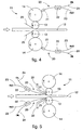
- the rolling train 10 shown partly and in diagram form in Fig. 1 comprises, as an example, four rolling stands 11, in this case four-high stands 11a, 11b, 11c and lid, arranged in sequence so as to perform progressive reductions in the thickness of a strip or plate 12 passing through.
- the invention is applied in the same way to roughing trains with 1 or 2 reversible or non-reversible stands, to pre-finishing trains with 1 or 2 non-reversible stands, to finishing trains with from 3 to 7 stands, to reversible finishing stands of the single type or of the tandem type such as is known in the state of the art by the name of steckel mill, inserted in any rolling line for plane products.
- Each stand 11 comprises, in this case, a pair of working rolls 13 and a mating pair of back-up rolls 14.
- Motion is supplied to the working rolls 13 (Fig. 2) by means of a single drive means 26 which, by means of reduction gear boxes indicated in their entirety by the reference number 15, transmits motion to respective spindles 16 associated with the respective rotation shafts 17 of the rolls 13.
- the motion command is of the twin-drive type, that is to say, with two independent motors 26, each of which commands a relative working roll 13, with or without intermediate reducers 15 and by means of the spindles 16.
- the invention provides means 18 to measure, continuously or at pre-set intervals; the actual torque transferred to each working roll 13 by the respective command means during the rolling cycle.
- the means 18 consist of detector elements 118 included in cooperation with the spindles 16.
- the means 18 consist of a control device 218 which acquires, processes and compares the electrical sizes of each independent motor 26.
- the means 18 are connected to a processing unit 19 suitable to compare the torque values to detect a possible difference, and to condition, if there is a difference and according to the entity thereof, the delivery of a mixture of water and lubricant, advantageously oil, in correspondence with the surface of the rolls.
- the processing unit 19 is provided to vary the percentage of oil in the mixture delivered, selectively for every roll, by increasing the percentage to the roll with the greater torque and/or reducing the percentage of oil to the roll with the lesser torque.
- the processing unit 19 (Figs. 2 and 3) is suitable to send command signals to delivery means 20 arranged in proximity with the surface of the respective rolls, the working rolls 13 and the back-up rolls 14.
- the delivery means 20 comprise at least a nozzle 21 to deliver the water-oil mixture and means 22 to adjust the percentage of oil in the mixture; the conduits of water and oil, respectively 23 and 24, flow into the means 22.
- the adjustment means 22 may consist of a proportional valve, a Venturi system or other appropriate mixing system able to vary substantially instantaneously the percentage of oil in the mixture according to the commands sent by the processing unit 19.
- the delivery nozzle 21 co-operates with the surface of a relative back-up roll 14 and the mixture delivered is transferred through contact to the surface of the relative working roll 13.
- a shutter 25 which prevents the formation of pools of mixture on the upper face of the rolled stock 12.
- the mixture is delivered directly onto the surface of the working rolls 13, in proximity with the area where the rolled stock 12 enters, by a delivery nozzle 21 assembled on a protective shutter 25, which also protects the nozzle 21 from knocking against the rolled stock.
- the invention functions in this way:
- the water-oil mixture delivered by the nozzles 21 to each of the two rolls 12 contains an equal percentage of oil, which can also be nil, or equal to the optimum percentage suitable to reduce wear on the working rolls without needlessly increasing the consumption of oil.
- the processing unit 19 When the processing unit 19, according to the measurements made by the measuring means 18, detects a difference in torque between the two working rolls 13 which exceeds a first pre-set threshold, percentage or absolute, it acts selectively on one or on both the adjustment means 22 to cause an increase in the percentage of oil delivered to the working roll 13 with the greater torque, and/or a reduction in the percentage of oil delivered to the working roll 13 with a lesser torque.
- This adjustment is continued until the measuring means 18 detect that a condition of substantially equal torque is restored, for example with a value of difference in torque below a second threshold which is lower than the first threshold; when this condition has been reached, the percentage of oil in the respective mixtures remains stabilised until a new condition of difference in torque occurs.
Landscapes
- Engineering & Computer Science (AREA)
- Mechanical Engineering (AREA)
- Metal Rolling (AREA)
- Cage And Drive Apparatuses For Elevators (AREA)
- Bending Of Plates, Rods, And Pipes (AREA)
- Spinning Or Twisting Of Yarns (AREA)
- Auxiliary Devices For Machine Tools (AREA)
- Lift-Guide Devices, And Elevator Ropes And Cables (AREA)
- Automatic Disk Changers (AREA)
- Vibration Prevention Devices (AREA)
- Moving Of Heads (AREA)
Claims (16)
- Verfahren zur Verringerung und Beseitigung von Schwingungen in einem Heisswalzgerüst (11) für flaches Walzgut (12) wie einen Strang oder ein Blech, wobei das Walzgerüst mittels einer kinematische Kette mit Antriebsmitteln (26) gekoppelte Arbeitswalzen (13) aufweist, wobei Mittel zum Zuführen einer Mischung aus Wasser und Schmiermittel zu der Oberfläche jeder der Arbeitswalzen (13) vorhanden sind, wobei das Verfahren dadurch gekennzeichnet ist, dass es entlang der kinematischen Kette die Messung des wirksamen Wertes des auf jede der Arbeitswalzen (13) übertragenen Drehmomentes und die gezielte Änderung des Anteils an Schmiermittel in jeder der Arbeitswalzen (13) zugeführten Mischung in Abhängigkeit einer gemessenen Differenz von den Arbeitswalzen (13) übertragenen Drehmoments bereitstellt, um die an den Walzen (13) auftretenden und durch die Drehmomentsdifferenz verursachten oszillierenden Horizontalkräfte zu beseitigen, wobei das Verfahren zum Erhöhen des Anteils an Schmiermittel in der Mischung führt, die derjenigen Arbeitswalze (13) zugeführt wird, welche ein größeres wirksames Drehmoment als die andere Arbeitswalze (13) aufweist, oder zum Erniedrigen des Anteils an Schmiermittel in der Mischung führt, die derjenigen Arbeitswalze (13) zugeführt wird, welche ein geringeres wirksames Drehmoment als die andere Arbeitswalze (13) aufweist.
- Verfahren nach Anspruch 1, dadurch gekennzeichnet, dass bei idealen Walzbedingungen, das heißt mit perfekter und symmetrischer Reibung, Walzenabrieb, Temperatur, gerade durchlaufendem Walzgut (12) und damit unter Bedingungen von im wesentlichen gleichen Drehmoment der beiden Arbeitswalzen (13), der Anteil von in der Mischung enthaltenem Schmiermittel, die zugeführt wird, für beide Arbeitswalzen (13) gleich ist.
- Verfahren nach Anspruch 2, dadurch gekennzeichnet, dass bei idealen Walzbedingungen, das heißt mit perfekter und symmetrischer Reibung, Walzenabrieb, Temperatur, gerade durchlaufendem Walzgut (12) und damit unter Bedingungen von im wesentlichen gleichen Drehmoment der beiden Arbeitswalzen (13), der Anteil von in der Mischung enthaltenem Schmiermittel, die zugeführt wird, für beide Arbeitswalzen (13) Null ist.
- Verfahren nach einem der vorangehenden Ansprüche, angewendet bei einem vier Walzen aufweisenden Walzgerüst mit jeweils mit einer Stützwalze (14) zusammenarbeitenden Arbeitswalzen (13), dadurch gekennzeichnet, dass es ein Zuführen der Wasser-Schmiermittel-Mischung in Abhängigkeit der Oberfläche der Stützwalzen (14) schafft.
- Verfahren nach Anspruch 1, dadurch gekennzeichnet, dass es zusammen oder im Wechsel mit der Änderung des Anteils von Schmiermittel in der Mischung, die den Arbeitswalzen (13) zugeführt wird, weiterhin in Abhängigkeit der Differenz des den Walzen (13) übertragenen Drehmoments die gezielte Änderung des Typs des Schmiermittels schafft.
- Vorrichtung für ein Heisswalzgerüst für flaches Walzgut (12) wie einen Strang oder ein Blech, wobei das Walzgerüst (11) Arbeitswalzen (13) aufweist, die mittels einer kinematischen Kette, die über mit der Drehwelle (17) der Arbeitswalzen (13) verbundene Transmissionselemente (16) verfügt, mit Antriebsmitteln (26) gekoppelt sind, und wobei Zuführmittel (20) vorhanden sind, um der Oberfläche jeder der Arbeitswalzen (13) eine Mischung aus Wasser und Schmiermittel zuzuführen, wobei die Vorrichtung dadurch gekennzeichnet ist, dass sie Messmittel (18) aufweist, die dazu eingerichtet sind, den wirksamen Wert des auf jede der Arbeitswalzen (13) übertragenen Drehmoments zu messen, und über Verarbeitungsmittel (19) verfügt, die dazu eingerichtet sind, die von den Messmittetn (18) einlaufenden Signale aufzunehmen, eine mögliche Differenz zwischen den Werten des auf jede der Arbeitswalzen (13) übertragenen Drehmoments zu berechnen und die Mittel (20) zum Zuführen der Mischung aus Wasser und Schmiermittel auf die Oberfläche der Arbeitswalzen (13) einzustellen, um den Anteil des in der Mischung enthaltenen Schmiermittels in Abhängigkeit der Differenz in den Drehmomentswerten zur Beseitigung der an den Walzen (13) auftretenden und durch die Drehmomentsdifferenz verursachten Horizontalkräfte zu verändern.
- Vorrichtung nach Anspruch 6, dadurch gekennzeichnet, dass die Antriebsmittel (26) für beide Arbeitswalzen (13) die gleichen sind und dass die Messmittel (18) aus Detektorelementen (118) bestehen, die an einer beliebigen Position entlang der kinematischen Kette zwischen den Antriebsmitteln (26) und der jeweiligen Arbeitswalze (13) angeordnet sind.
- Vorrichtung nach Anspruch 6 und 7, dadurch gekennzeichnet, dass die Transmissionselemente (16) aus Spindeln bestehen und dass die Detektorelemente (118) unter Zusammenwirken mit jeder der Spindeln (16) angeordnet sind.
- Vorrichtung nach Anspruch 6, dadurch gekennzeichnet, dass die Antriebsmittel (26) für die beiden Arbeitswalzen (13) unabhängig voneinander sind und dass die Messmittel (18) aus einer Steuervorrichtung (218) bestehen, die die elektrischen Größen von jedem der unabhängigen Antriebsmittel (26) aufnehmen, verarbeiten und vergleichen.
- Vorrichtung nach den Ansprüchen 6 bis 9, dadurch gekennzeichnet, dass die zuführmittel (20) wenigstens eine Zuführdüse (21), die mit der Oberfläche der jeweiligen Arbeitswalze (13) zusammenwirkt, und Mittel (22) aufweisen, um den Anteil von in der zugeführten Mischung enthaltenem Schmiermittel einzustellen, wobei die Einstellmittel (22) durch die Verarbeitungsmittel (19) beeinflusst sind.
- Vorrichtung nach den Ansprüchen 6 bis 10, dadurch gekennzeichnet, dass die Zuführdüse (21) an einem Verschluss (25) angeordnet ist, der nahe des Bereiches angeordnet ist, in dem das Walzgut (12) in das Gerüst (11) einläuft, und dazu eingerichtet ist, sowohl das Bilden von Mischungsablagerungen auf der Oberseite des Walzgutes (12) als auch von möglichen Schlägen gegen das Walzgut (12) selbst zu verhindern.
- Vorrichtung nach den Ansprüchen 6 bis 11, dadurch gekennzeichnet, dass das Walzgerüst (11) des Typs mit vier Walzen mit mit jeder der Arbeitswalzen (13) zusammenwirkenden Stützwalzen (14) ist und dass die Zuführdüsen (21) im Zusammenwirken mit der Oberfläche jeder der Stützwalzen (14) vorhanden sind.
- Vorrichtung nach den Ansprüchen 6 bis 12, dadurch gekennzeichnet, dass das Walzgerüst (11) von einer Vorwalzstraße (10) mit einem oder zwei reversibel oder nicht reversibel arbeitenden Gerüsten umfasst ist.
- Vorrichtung nach den Ansprüchen 6 bis 12, dadurch gekennzeichnet, dass das Walzgerüst (11) von einer Zwischenwaizstraße (10) mit einem oder zwei reversibel oder nicht reversibel arbeitenden Gerüsten umfasst ist.
- Vorrichtung nach den Ansprüchen 6 bis 12, dadurch gekennzeichnet, dass das Walzgerüst (11) von einer Fertigwalzstraße (10) mit drei bis sieben Gerüsten umfasst ist.
- Vorrichtung nach Anspruch 6, dadurch gekennzeichnet, dass die Zuführmittel (20) auch dazu eingerichtet sind, selektiv auf die Oberfläche der Arbeitswalzen (13) verschiedene Arten von Schmiermittel zuzuführen, wobei das zuzuführende Schmiermittel in Abhängigkeit der Differenz der durch die Messmittel (18) detektierten Drehmomentswerte ausgewählt ist.
Applications Claiming Priority (2)
| Application Number | Priority Date | Filing Date | Title |
|---|---|---|---|
| ITUD980157 | 1998-09-14 | ||
| IT1998UD000157A IT1302766B1 (it) | 1998-09-14 | 1998-09-14 | Procedimento di riduzione ed eliminazione delle vibrazioni inuna gabbia di laminazione e relativo dispositivo |
Publications (2)
| Publication Number | Publication Date |
|---|---|
| EP1005925A1 EP1005925A1 (de) | 2000-06-07 |
| EP1005925B1 true EP1005925B1 (de) | 2002-12-04 |
Family
ID=11422742
Family Applications (1)
| Application Number | Title | Priority Date | Filing Date |
|---|---|---|---|
| EP99118168A Revoked EP1005925B1 (de) | 1998-09-14 | 1999-09-13 | Verfahren und Vorrichtung zur Verringerung und Beseitigung von Schwingungen in einem Walzgerüst |
Country Status (8)
| Country | Link |
|---|---|
| US (1) | US6276183B1 (de) |
| EP (1) | EP1005925B1 (de) |
| AT (1) | ATE228895T1 (de) |
| AU (1) | AU749934B2 (de) |
| CA (1) | CA2343834A1 (de) |
| DE (1) | DE69904283T2 (de) |
| IT (1) | IT1302766B1 (de) |
| WO (1) | WO2000015363A1 (de) |
Families Citing this family (8)
| Publication number | Priority date | Publication date | Assignee | Title |
|---|---|---|---|---|
| DE102004060341B3 (de) * | 2004-12-15 | 2006-07-13 | Siemens Ag | Walzgerüst |
| WO2008136146A1 (ja) * | 2007-05-01 | 2008-11-13 | Toshiba Mitsubishi-Electric Industrial Systems Corporation | 圧延ロール電動機の駆動装置 |
| KR101249168B1 (ko) * | 2009-12-18 | 2013-03-29 | 주식회사 포스코 | 냉간압연에서의 품질이상 예지 시스템과 그 방법 |
| DE102011090098A1 (de) | 2011-12-29 | 2013-07-04 | Sms Siemag Ag | Verfahren und Vorrichtung zum Walzen von Walzgut sowie Verwendung eines Kühlschmierstoffes |
| CN110756593B (zh) * | 2018-07-26 | 2020-10-27 | 宝山钢铁股份有限公司 | 一种抑制冷连轧机组振动的张力制度优化方法 |
| EP4098377A4 (de) * | 2020-03-10 | 2023-11-08 | Nippon Steel Corporation | Biegevorrichtung, ausrüstung zur herstellung von kanaldielen, biegeverfahren und verfahren zur herstellung von kanaldielen |
| JP7020530B1 (ja) * | 2020-10-29 | 2022-02-16 | Jfeスチール株式会社 | 冷間圧延設備、冷間圧延方法、及び金属板の製造方法 |
| CN120838835B (zh) * | 2025-09-23 | 2026-01-06 | 江苏甬金金属科技有限公司 | 一种具有防偏移功能的芯片支架用高镍不锈钢冷轧设备 |
Family Cites Families (11)
| Publication number | Priority date | Publication date | Assignee | Title |
|---|---|---|---|---|
| DE890928C (de) * | 1949-11-01 | 1954-09-20 | Junghans Geb Ag | Chronograph ohne Saeulenrad und Zaehlrad |
| US3134279A (en) * | 1961-05-26 | 1964-05-26 | Davy & United Eng Co Ltd | Rolling mills |
| LU82911A1 (fr) * | 1980-11-04 | 1982-06-30 | Centre Rech Metallurgique | Perfectionnements aux procedes de conduite des laminoirs |
| JPS61206512A (ja) * | 1985-03-08 | 1986-09-12 | Nippon Kokan Kk <Nkk> | 冷間圧延におけるチヤタリング防止装置 |
| JPS61269903A (ja) * | 1985-05-24 | 1986-11-29 | Kawasaki Steel Corp | 圧延機のロ−ルスリツプ防止方法 |
| JPH01245905A (ja) * | 1988-03-25 | 1989-10-02 | Kobe Steel Ltd | 圧延機の冷却液噴射装置 |
| FR2682896B1 (fr) * | 1991-10-29 | 1995-07-07 | Lorraine Laminage | Dispositif de refroidissement et de lubrification d'une piece metallique soumise a des contraintes thermiques et mecaniques elevees. |
| JP3098354B2 (ja) * | 1993-06-02 | 2000-10-16 | 新日本製鐵株式会社 | 圧延機の振動防止方法 |
| EP0638375B1 (de) * | 1993-07-13 | 1996-11-13 | Siemens Aktiengesellschaft | Verfahren und Vorrichtung zur Ratterüberwachung bei Zwillingsantrieben von Walzgerüsten |
| DE4408289A1 (de) * | 1994-03-11 | 1995-09-14 | Siemens Ag | Walzwerk, insbesondere Kaltwalzwerk |
| JP3615813B2 (ja) * | 1994-12-28 | 2005-02-02 | 株式会社日立製作所 | 作業ロールクロス圧延機のロール間潤滑油供給システム |
-
1998
- 1998-09-14 IT IT1998UD000157A patent/IT1302766B1/it active IP Right Grant
-
1999
- 1999-09-13 AT AT99118168T patent/ATE228895T1/de not_active IP Right Cessation
- 1999-09-13 CA CA002343834A patent/CA2343834A1/en not_active Abandoned
- 1999-09-13 EP EP99118168A patent/EP1005925B1/de not_active Revoked
- 1999-09-13 DE DE69904283T patent/DE69904283T2/de not_active Revoked
- 1999-09-13 AU AU54404/99A patent/AU749934B2/en not_active Ceased
- 1999-09-13 WO PCT/IB1999/001535 patent/WO2000015363A1/en not_active Ceased
- 1999-09-14 US US09/395,157 patent/US6276183B1/en not_active Expired - Fee Related
Also Published As
| Publication number | Publication date |
|---|---|
| DE69904283T2 (de) | 2003-05-28 |
| CA2343834A1 (en) | 2000-03-23 |
| EP1005925A1 (de) | 2000-06-07 |
| AU5440499A (en) | 2000-04-03 |
| ITUD980157A1 (it) | 2000-03-14 |
| ATE228895T1 (de) | 2002-12-15 |
| WO2000015363A1 (en) | 2000-03-23 |
| DE69904283D1 (de) | 2003-01-16 |
| US6276183B1 (en) | 2001-08-21 |
| IT1302766B1 (it) | 2000-09-29 |
| AU749934B2 (en) | 2002-07-04 |
Similar Documents
| Publication | Publication Date | Title |
|---|---|---|
| EP0451874B2 (de) | Vier-Walzen-Walzwerk | |
| EP1195205A2 (de) | Walzwerkseinstellsystem zur Profil- und Planheitsregelung | |
| US5448901A (en) | Method for controlling axial shifting of rolls | |
| EP0743107B1 (de) | Verbesserungen in oder in Verband mit einer Einrichtung zum Kreuzen oder axialen Verschieben von Walzen | |
| CA2712013C (en) | Rolling mill and rolling method for flat products of steel | |
| EP1005925B1 (de) | Verfahren und Vorrichtung zur Verringerung und Beseitigung von Schwingungen in einem Walzgerüst | |
| EP0555882B1 (de) | Tandemwalzsystem und Walzenschrägwalzwerk | |
| US6076388A (en) | Rolling mill, hot rolling system, rolling method and rolling mill revamping method | |
| AU2009222686B2 (en) | Rolling mill and rolling method for flat products of steel | |
| US5666837A (en) | Rolling mill and method of using the same | |
| EP1042084B1 (de) | Verfahren und vorrichtung zur beseitigung des spiels zwischen den einbaustücken und den jeweiligen stützblöcken in quartowalzgerüsten | |
| JP3249313B2 (ja) | 圧延機及び圧延機の圧延方法並びに圧延機の使用方法 | |
| EP0110556A2 (de) | Walzverfahren für ein Duo-Warmwalzwerk und Schmalbanderzeugnis | |
| JP3291219B2 (ja) | 圧延方法、圧延機、および圧延設備 | |
| WO2020235199A1 (ja) | 圧延機、並びに圧延方法及びワークロールの運用方法 | |
| JPH057081B2 (de) | ||
| EP1127627B1 (de) | Verfahren zum warmfertigwalzen von stabstahl | |
| JP2002035808A (ja) | クロス圧延機およびクロス圧延方法 | |
| SU774641A1 (ru) | Устройство автоматического устранени проскальзывани рабочих валков относительно опорных | |
| RU2467813C1 (ru) | Способ продольной прокатки полос | |
| EP0111865A2 (de) | Walzwerk mit verschiedenen Umfangsgeschwindigkeiten | |
| Ammerling | Energy saving in 3-roll mills for wire rod and bar | |
| JPH0131962B2 (de) | ||
| JP2002086204A (ja) | 冷間タンデム圧延における板幅制御方法 |
Legal Events
| Date | Code | Title | Description |
|---|---|---|---|
| PUAI | Public reference made under article 153(3) epc to a published international application that has entered the european phase |
Free format text: ORIGINAL CODE: 0009012 |
|
| AK | Designated contracting states |
Kind code of ref document: A1 Designated state(s): AT BE CH CY DE DK ES FI FR GB GR IE IT LI LU MC NL PT SE |
|
| AX | Request for extension of the european patent |
Free format text: AL;LT;LV;MK;RO;SI |
|
| 17P | Request for examination filed |
Effective date: 20001128 |
|
| AKX | Designation fees paid |
Free format text: AT BE CH CY DE DK ES FI FR GB GR IE IT LI LU MC NL PT SE |
|
| AXX | Extension fees paid |
Free format text: SI PAYMENT 20001128 |
|
| 17Q | First examination report despatched |
Effective date: 20010223 |
|
| GRAG | Despatch of communication of intention to grant |
Free format text: ORIGINAL CODE: EPIDOS AGRA |
|
| GRAG | Despatch of communication of intention to grant |
Free format text: ORIGINAL CODE: EPIDOS AGRA |
|
| GRAH | Despatch of communication of intention to grant a patent |
Free format text: ORIGINAL CODE: EPIDOS IGRA |
|
| GRAH | Despatch of communication of intention to grant a patent |
Free format text: ORIGINAL CODE: EPIDOS IGRA |
|
| GRAA | (expected) grant |
Free format text: ORIGINAL CODE: 0009210 |
|
| AK | Designated contracting states |
Kind code of ref document: B1 Designated state(s): AT BE CH CY DE DK ES FI FR GB GR IE IT LI LU MC NL PT SE |
|
| AX | Request for extension of the european patent |
Free format text: SI PAYMENT 20001128 |
|
| PG25 | Lapsed in a contracting state [announced via postgrant information from national office to epo] |
Ref country code: NL Free format text: LAPSE BECAUSE OF FAILURE TO SUBMIT A TRANSLATION OF THE DESCRIPTION OR TO PAY THE FEE WITHIN THE PRESCRIBED TIME-LIMIT Effective date: 20021204 Ref country code: LI Free format text: LAPSE BECAUSE OF FAILURE TO SUBMIT A TRANSLATION OF THE DESCRIPTION OR TO PAY THE FEE WITHIN THE PRESCRIBED TIME-LIMIT Effective date: 20021204 Ref country code: GR Free format text: LAPSE BECAUSE OF FAILURE TO SUBMIT A TRANSLATION OF THE DESCRIPTION OR TO PAY THE FEE WITHIN THE PRESCRIBED TIME-LIMIT Effective date: 20021204 Ref country code: FI Free format text: LAPSE BECAUSE OF FAILURE TO SUBMIT A TRANSLATION OF THE DESCRIPTION OR TO PAY THE FEE WITHIN THE PRESCRIBED TIME-LIMIT Effective date: 20021204 Ref country code: CH Free format text: LAPSE BECAUSE OF FAILURE TO SUBMIT A TRANSLATION OF THE DESCRIPTION OR TO PAY THE FEE WITHIN THE PRESCRIBED TIME-LIMIT Effective date: 20021204 Ref country code: BE Free format text: LAPSE BECAUSE OF FAILURE TO SUBMIT A TRANSLATION OF THE DESCRIPTION OR TO PAY THE FEE WITHIN THE PRESCRIBED TIME-LIMIT Effective date: 20021204 |
|
| REF | Corresponds to: |
Ref document number: 228895 Country of ref document: AT Date of ref document: 20021215 Kind code of ref document: T |
|
| REG | Reference to a national code |
Ref country code: GB Ref legal event code: FG4D |
|
| REG | Reference to a national code |
Ref country code: CH Ref legal event code: EP |
|
| REG | Reference to a national code |
Ref country code: IE Ref legal event code: FG4D |
|
| REF | Corresponds to: |
Ref document number: 69904283 Country of ref document: DE Date of ref document: 20030116 |
|
| PG25 | Lapsed in a contracting state [announced via postgrant information from national office to epo] |
Ref country code: SE Free format text: LAPSE BECAUSE OF FAILURE TO SUBMIT A TRANSLATION OF THE DESCRIPTION OR TO PAY THE FEE WITHIN THE PRESCRIBED TIME-LIMIT Effective date: 20030304 Ref country code: DK Free format text: LAPSE BECAUSE OF FAILURE TO SUBMIT A TRANSLATION OF THE DESCRIPTION OR TO PAY THE FEE WITHIN THE PRESCRIBED TIME-LIMIT Effective date: 20030304 |
|
| PG25 | Lapsed in a contracting state [announced via postgrant information from national office to epo] |
Ref country code: PT Free format text: LAPSE BECAUSE OF FAILURE TO SUBMIT A TRANSLATION OF THE DESCRIPTION OR TO PAY THE FEE WITHIN THE PRESCRIBED TIME-LIMIT Effective date: 20030305 |
|
| ET | Fr: translation filed | ||
| NLV1 | Nl: lapsed or annulled due to failure to fulfill the requirements of art. 29p and 29m of the patents act | ||
| REG | Reference to a national code |
Ref country code: CH Ref legal event code: PL |
|
| PG25 | Lapsed in a contracting state [announced via postgrant information from national office to epo] |
Ref country code: ES Free format text: LAPSE BECAUSE OF FAILURE TO SUBMIT A TRANSLATION OF THE DESCRIPTION OR TO PAY THE FEE WITHIN THE PRESCRIBED TIME-LIMIT Effective date: 20030627 |
|
| PLBQ | Unpublished change to opponent data |
Free format text: ORIGINAL CODE: EPIDOS OPPO |
|
| PLBI | Opposition filed |
Free format text: ORIGINAL CODE: 0009260 |
|
| PLAQ | Examination of admissibility of opposition: information related to despatch of communication + time limit deleted |
Free format text: ORIGINAL CODE: EPIDOSDOPE2 |
|
| PLBI | Opposition filed |
Free format text: ORIGINAL CODE: 0009260 |
|
| PG25 | Lapsed in a contracting state [announced via postgrant information from national office to epo] |
Ref country code: LU Free format text: LAPSE BECAUSE OF NON-PAYMENT OF DUE FEES Effective date: 20030913 Ref country code: GB Free format text: LAPSE BECAUSE OF NON-PAYMENT OF DUE FEES Effective date: 20030913 Ref country code: CY Free format text: LAPSE BECAUSE OF FAILURE TO SUBMIT A TRANSLATION OF THE DESCRIPTION OR TO PAY THE FEE WITHIN THE PRESCRIBED TIME-LIMIT Effective date: 20030913 |
|
| PG25 | Lapsed in a contracting state [announced via postgrant information from national office to epo] |
Ref country code: IE Free format text: LAPSE BECAUSE OF NON-PAYMENT OF DUE FEES Effective date: 20030915 |
|
| PG25 | Lapsed in a contracting state [announced via postgrant information from national office to epo] |
Ref country code: MC Free format text: LAPSE BECAUSE OF NON-PAYMENT OF DUE FEES Effective date: 20030930 |
|
| PLAX | Notice of opposition and request to file observation + time limit sent |
Free format text: ORIGINAL CODE: EPIDOSNOBS2 |
|
| 26 | Opposition filed |
Opponent name: SMS DEMAG AG Effective date: 20030822 |
|
| 26 | Opposition filed |
Opponent name: SIEMENS AG, ABTEILUNG CT IP I&S Effective date: 20030904 Opponent name: SMS DEMAG AG Effective date: 20030822 |
|
| GBPC | Gb: european patent ceased through non-payment of renewal fee |
Effective date: 20030913 |
|
| REG | Reference to a national code |
Ref country code: IE Ref legal event code: MM4A |
|
| PLBP | Opposition withdrawn |
Free format text: ORIGINAL CODE: 0009264 |
|
| RDAF | Communication despatched that patent is revoked |
Free format text: ORIGINAL CODE: EPIDOSNREV1 |
|
| PGFP | Annual fee paid to national office [announced via postgrant information from national office to epo] |
Ref country code: FR Payment date: 20050831 Year of fee payment: 7 |
|
| PGFP | Annual fee paid to national office [announced via postgrant information from national office to epo] |
Ref country code: AT Payment date: 20050914 Year of fee payment: 7 |
|
| PGFP | Annual fee paid to national office [announced via postgrant information from national office to epo] |
Ref country code: DE Payment date: 20050926 Year of fee payment: 7 |
|
| RDAG | Patent revoked |
Free format text: ORIGINAL CODE: 0009271 |
|
| STAA | Information on the status of an ep patent application or granted ep patent |
Free format text: STATUS: PATENT REVOKED |
|
| 27W | Patent revoked |
Effective date: 20050908 |
|
| PGFP | Annual fee paid to national office [announced via postgrant information from national office to epo] |
Ref country code: IT Payment date: 20060930 Year of fee payment: 8 |
|
| PLAB | Opposition data, opponent's data or that of the opponent's representative modified |
Free format text: ORIGINAL CODE: 0009299OPPO |