EP1004816B1 - Luminaire with internal supporting plate which can be mounted on one of two different levels - Google Patents
Luminaire with internal supporting plate which can be mounted on one of two different levels Download PDFInfo
- Publication number
- EP1004816B1 EP1004816B1 EP19990402863 EP99402863A EP1004816B1 EP 1004816 B1 EP1004816 B1 EP 1004816B1 EP 19990402863 EP19990402863 EP 19990402863 EP 99402863 A EP99402863 A EP 99402863A EP 1004816 B1 EP1004816 B1 EP 1004816B1
- Authority
- EP
- European Patent Office
- Prior art keywords
- plate
- lighting unit
- base
- unit according
- fixing sleeves
- Prior art date
- Legal status (The legal status is an assumption and is not a legal conclusion. Google has not performed a legal analysis and makes no representation as to the accuracy of the status listed.)
- Expired - Lifetime
Links
Images


Classifications
-
- F—MECHANICAL ENGINEERING; LIGHTING; HEATING; WEAPONS; BLASTING
- F21—LIGHTING
- F21S—NON-PORTABLE LIGHTING DEVICES; SYSTEMS THEREOF; VEHICLE LIGHTING DEVICES SPECIALLY ADAPTED FOR VEHICLE EXTERIORS
- F21S8/00—Lighting devices intended for fixed installation
- F21S8/02—Lighting devices intended for fixed installation of recess-mounted type, e.g. downlighters
-
- F—MECHANICAL ENGINEERING; LIGHTING; HEATING; WEAPONS; BLASTING
- F21—LIGHTING
- F21V—FUNCTIONAL FEATURES OR DETAILS OF LIGHTING DEVICES OR SYSTEMS THEREOF; STRUCTURAL COMBINATIONS OF LIGHTING DEVICES WITH OTHER ARTICLES, NOT OTHERWISE PROVIDED FOR
- F21V15/00—Protecting lighting devices from damage
- F21V15/01—Housings, e.g. material or assembling of housing parts
-
- F—MECHANICAL ENGINEERING; LIGHTING; HEATING; WEAPONS; BLASTING
- F21—LIGHTING
- F21V—FUNCTIONAL FEATURES OR DETAILS OF LIGHTING DEVICES OR SYSTEMS THEREOF; STRUCTURAL COMBINATIONS OF LIGHTING DEVICES WITH OTHER ARTICLES, NOT OTHERWISE PROVIDED FOR
- F21V23/00—Arrangement of electric circuit elements in or on lighting devices
Definitions
- the present invention relates generally to the luminaires of the kind comprising a base, which has a bottom, and a plate, which, for the support of various constituents, intervenes at a distance from this bottom, the base comprising, for the maintenance of this plate, securing means suitable for such maintenance.
- portholes which include, also, to close the assembly, and, preferably, to close this together tightly, a cover or a cover, which, of course, is at least partly translucent.
- the base may have, in addition to its bottom, a side wall, and, thus forming itself a box body, a simple cover is enough to close it.
- the base can essentially be reduced to its bottom, and, to close the assembly, a cover is then implemented, in the general shape of a bell, which presents by itself the necessary side wall.
- this light source can be either a fluorescent source or a source incandescent.
- a source incandescent light requires, above the plate, a volume higher than that satisfied with a fluorescent light source, and conversely, she is satisfied with a lower volume below this platinum.
- the present invention generally relates to a provision which, by allowing a standardization of the manufacturing, leads advantageously to a reduction of these costs.
- a luminaire of the kind comprising a base, which has a bottom, and a plate, which, for the support of various constituents, intervenes at a distance from this bottom, the base comprising, for the maintenance of this plate, means of securing specific to a such support, this luminaire being generally characterized in that the base includes securing means at two different levels by compared to its background.
- the document EP-A-0 199 230 describes a lighting device comprising two compartments in each of which is fixed a printed guide card in a guide groove.
- the means of subjugation provided on the base have, at a distance from each other, in a preferred form of the invention, at least two fixing chimneys, and, for access to the means for securing the lower level, the plate comprises, jointly, at a distance from each other, in correspondence with these fixing chimneys, two recesses.
- the luminaire 10 comprises, in particular, a base 11, which has a bottom 12, and a plate 13, which, for the support of various constituents, and, in particular, for that of a light source 14A, 14B, as shown schematically in broken lines in Figures 6 and 8, intervenes at a distance from the bottom 12, the base 11 comprising, for the maintenance of this plate, and according to arrangements described in more detail later, means subjugation 15A, 15B specific to such maintenance.
- the base 11 will only be partially described in the following.
- the base 11 comprises, in addition to its bottom 12, and, in practice, integrally with it, a side wall 16, which, at its outlet, forms, peripherally, projecting outwards, a ledge 18.
- This base 11 thus generally forms a box body.
- the side wall 16 of the base 11 forms, along of its periphery, in recess from its current part 19, at distance from its outlet, a bench 20, which projects towards the inside of the base 11, and which, in practice, extends to the bottom 12 thereof.
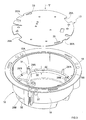
- the base 11 has, in plan, a generally circular outline.
- the plate 13 has, moreover, itself, a generally circular contour.
- this plate 13 is substantially complementary to that of the main part 19 of the side wall 16 of the base 11, this running part 19 of the side wall 16 being the portion of the latter which extends between the bench seat 20 and its outlet.
- the luminaire 10 comprises, also, in addition to the base 11 and the plate 13, a cover 22, which closes the base 11, and which, of course, is at least partly translucent.
- this cover 22 comprises, in its central zone, a verrine 23, which forms a diffuser, and, at its periphery, around of this verrine 23, for its fixing to the base 11, a crown 24, which forms hubcap.
- the crown 24 of this cover 22 presents, from place to place, wells 25, for the passage of screws 26 suitable for its attachment to the rim 18 of the base 11, the wells 27 opening out correspondence to the surface of this rim 18 for the screwing of these screws 26.
- the base 11 comprises means 15A, 15B at two levels NA, NB different from its background 12.
- the means of subjugation 15A include, at a distance from each other, in the embodiments shown, at least two fixing chimneys 28A, and, for access to securing means 15B of the lower NB level, the plate 13 includes, at a distance from each other, in correspondence with these chimneys fixing 28A, two recesses 29A.
- the fixing chimneys 28A of the upper level NA intervene in the vicinity of the side wall 16 of the base 11, and the corresponding recesses 29A of the plate 13 are notches which act on the periphery of this plate 13.
- the means of subjugation 15A also include, in the embodiments shown, distance from each other, and distance from the fixing chimneys 28A, at at least two support ribs 28'A, and, for access to the means 15B of the lower NB level, the plate 13 comprises, at distance from each other, in correspondence with these support ribs 28'A, two recesses 29'A.
- the support ribs 28'A alternate with the fixing chimneys 28A.
- the fixing chimneys 28A of the upper level NA make projection on this bench 20, and, more precisely, on the upper surface 30 thereof, towards the outlet of the base 11, and it is the same for the support ribs 28'A.
- the chimneys 28A fasteners are arranged at a slight distance from the main part 19 of the side wall 16, and they are each connected thereto by a rib of stiffening 31 which extends substantially perpendicular to this part side 19 of the side wall 16.
- the ribs 28'A support each extend substantially perpendicular to the part current 19 of the side wall 16, from the latter, and over the entire width of the bench 20.
- the means of securing 15B also, at a distance from each other, in the embodiment shown, at least two fixing chimneys 28B.
- these fixing chimneys 28A, 28B are arranged in positions diametrically opposite one with respect to the other at each of the levels NA, NB, and, from one level NA, NB to the other, they are arranged in a cross.
- the fixing chimneys 28A, 28B are 90 ° two by two.
- the fixing chimneys 28B of the lower NB level are at least partially engaged in the bench seat 20, or, more precisely, in the side 32 of this bench seat 20.
- the fixing chimneys 28B of the lower NB level extend from the bottom 12 of the base 11, and they protrude slightly on the bench 20, and, more precisely, on the upper surface 30 of this, in the direction of the outlet of this base 11.
- the fixing chimneys 28A of the higher level NA and the fixing chimneys 28B of the lower NB level are preferably established along the same circumference C, which corresponds, substantially, with the outline of the sidewall 32 of the bench seat 20, FIG. 4.
- the plate 13 has two holes 33, which are established along a circumference C 'of the same diameter as the circumference C along from which these fixing chimneys 28A, 28B are established, and which are arranged in diametrically opposite positions relative to each other.
- the holes 33 of the plate 13 are elongated in keyholes.
- the means of subjugation 15B also, at a distance from each other, in the forms of embodiment shown, at least two support ribs 28'B.
- the support ribs 28'B each extend substantially perpendicular to the main part 19 side wall 16, from the latter, over the entire width of the bench 20, and the fixing chimneys 28B are themselves each connected to this main part 19 of the side wall 16 of the base 11 by a stiffening rib 34 which extends substantially radially with respect to to base 11.
- the plate 13 includes, for reasons which have not been explained here, other days that the only recesses 29A, 29'A and that the only holes 33.
- the light source 14A to be used is a light source fluorescent.
- ballast 36 As is known, must be associated with such a light source 14A fluorescent, in addition to a 35A terminal block, a ballast 36, which is relatively bulky.
- this fluorescent light source 14A is installed on the upper surface of the plate 13, as shown schematically in lines interrupted in Figure 6.
- terminal block 35A and ballast 36 are installed on the lower surface of this plate 13, as also shown diagrammatically in lines interrupted in this figure 6.
- the plate 13 thus equipped, at least, with such a 14A fluorescent light source, 35A terminal block and 36 ballast, is located at the higher NA level in the base 11.
- the corresponding fixing screws can advantageously be installed in advance in the chimneys of fixing 28A, without however being entirely screwed into them, and, after have been engaged on these fixing screws by the rounded part of its holes 33, the plate 13 is, as shown diagrammatically by the arrow F in FIG. 7, pivoted around the axis A of the assembly at an angle sufficient for it to engage under the head of these fixing screws by the elongated part of these holes 33.
- the light source 14B to be used is a light source incandescent.
- this light source 14B is located on the upper surface of the plate 13, and, on the lower surface thereof, is installed a 35B terminal block.
- the plate 13 thus equipped with such a source luminous 14B incandescent and this 35B terminal block is installed on the NB level lower in the base 11.
- the angular extension of the recesses 29A, 29'A of the plate 13 is, by construction, sufficient for that the fixing chimneys 28A of the securing means 15A of the upper level NA and the supporting ribs 28'A associated with these chimneys fixing 28A do not oppose this pivoting of the plate 13.
- the plate 13 intervenes, each time, globally transversely in the base 11, that is to say globally perpendicular to the axis A of the assembly, substantially parallel to the bottom 12 of this base 11.
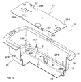
- the base 11 a in plan, a generally rectangular contour, and it is the same for the plate 13.
- the base 11 has two fixing chimneys 28A, only one of which is visible in FIG. 10, two fixing chimneys 28B, only one of which is also visible in this figure 10, two support ribs 28'A and two support ribs 28'B.
- the plate 13 has, at its periphery, two recesses 29A, in this case notches, one of which occurs in a corner area, two recesses 29'A, and two holes 33.
- the plate 13 is shown in the position for which it is capable of being located at the lower NB level, not shown, of the base 11, its holes 33 appearing in line with the fixing chimneys 28B of it, however that its recesses 29A are to the right of fixing chimneys 28A, and that its recesses 29'A are in line with support ribs 28'A.
Description
La présente invention concerne d'une manière générale les luminaires du genre comportant un socle, qui présente un fond, et une platine, qui, pour le support de divers constituants, intervient à distance de ce fond, le socle comportant, pour le maintien de cette platine, des moyens d'assujettissement propres à un tel maintien.The present invention relates generally to the luminaires of the kind comprising a base, which has a bottom, and a plate, which, for the support of various constituents, intervenes at a distance from this bottom, the base comprising, for the maintenance of this plate, securing means suitable for such maintenance.
Elle vise plus particulièrement, mais non nécessairement exclusivement, ceux de ces luminaires, alors communément appelés hublots, qui comportent, également, pour refermer l'ensemble, et, préférentiellement, pour refermer cet ensemble de manière étanche, un couvercle ou un capot, qui, bien entendu, est au moins en partie translucide.More specifically, but not necessarily exclusively, it those of these lights, then commonly called portholes, which include, also, to close the assembly, and, preferably, to close this together tightly, a cover or a cover, which, of course, is at least partly translucent.
Par exemple, et cela est le cas pour les luminaires à encastrer, le socle peut comporter, outre son fond, une paroi latérale, et, formant ainsi par lui-même un corps de boíte, un simple couvercle suffit à le refermer.For example, and this is the case for recessed luminaires, the base may have, in addition to its bottom, a side wall, and, thus forming itself a box body, a simple cover is enough to close it.
En variante, et cela peut être le cas pour un luminaire à disposer en saillie, le socle peut se réduire pour l'essentiel à son fond, et, pour refermer l'ensemble, il est alors mis en oeuvre un capot, en forme générale de cloche, qui présente par lui-même la paroi latérale nécessaire.Alternatively, and this may be the case for a luminaire to be arranged in protruding, the base can essentially be reduced to its bottom, and, to close the assembly, a cover is then implemented, in the general shape of a bell, which presents by itself the necessary side wall.
Le problème, en l'espèce, est que, dans l'un et l'autre cas, le couvercle fermant le hublot, le volume disponible tant en dessous de la platine qu'au-dessus de celle-ci est limité, et bien déterminé.The problem here is that in either case the cover closing the window, the volume available both below the deck and above of it is limited, and well determined.
Or, pour un volume global donné pour l'ensemble, la répartition à faire entre le volume libre sous la platine et le volume libre au-dessus de celle-ci est différente suivant la nature de la source lumineuse mise en oeuvre, cette source lumineuse pouvant être soit une source fluorescente, soit une source incandescente.Now, for a given overall volume for the whole, the distribution to be made between the free volume under the turntable and the free volume above it is different depending on the nature of the light source used, this light source can be either a fluorescent source or a source incandescent.
En effet, les constituants à mettre en oeuvre dans l'un et l'autre cas sont différents, et donc, aussi, leur encombrement, et les contraintes d'échauffement à respecter sont également différentes. Indeed, the constituents to be used in both cases are different, and therefore, too, their size, and the constraints are also different.
En pratique, les autres conditions étant égales par ailleurs, une source lumineuse incandescente nécessite, au-dessus de la platine, un volume supérieur à celui dont se satisfait une source lumineuse fluorescente, et, à l'inverse, elle se satisfait, elle, d'un volume inférieur en dessous de cette platine.In practice, the other conditions being equal, a source incandescent light requires, above the plate, a volume higher than that satisfied with a fluorescent light source, and conversely, she is satisfied with a lower volume below this platinum.
Pour répondre à de telles conditions, il est usuel, à ce jour, de prévoir deux réalisations différentes, l'une propre à la mise en oeuvre d'une source lumineuse incandescente, l'autre propre à ia mise en oeuvre d'une source lumineuse fluorescente, au détriment des coûts de fabrication et de gestion de ces réalisations.To meet such conditions, it is customary, to date, to provide two different realizations, one specific to the implementation of a source incandescent light, the other specific to the implementation of a source fluorescent light, at the expense of manufacturing and management costs these achievements.
La présente invention a d'une manière générale pour objet une disposition qui, en permettant une standardisation des fabrications, conduit avantageusement à une réduction de ces coûts.The present invention generally relates to a provision which, by allowing a standardization of the manufacturing, leads advantageously to a reduction of these costs.
De manière plus précise, elle a pour objet un luminaire du genre comportant un socle, qui présente un fond, et une platine, qui, pour le support de divers constituants, intervient à distance de ce fond, le socle comportant, pour le maintien de cette platine, des moyens d'assujettissement propres à un tel maintien, ce luminaire étant d'une manière générale caractérisé en ce que le socle comporte des moyens d'assujettissement à deux niveaux différents par rapport à son fond.More specifically, it relates to a luminaire of the kind comprising a base, which has a bottom, and a plate, which, for the support of various constituents, intervenes at a distance from this bottom, the base comprising, for the maintenance of this plate, means of securing specific to a such support, this luminaire being generally characterized in that the base includes securing means at two different levels by compared to its background.
Grâce à une telle disposition, qui permet de faire varier de manière inverse le volume disponible au-dessus de la platine et le volume disponible en dessous de celle-ci, un même socle, et une même platine, conviennent avantageusement tant à la mise en oeuvre d'une source lumineuse incandescente qu'à la mise en oeuvre d'une source lumineuse fluorescente, en permettant, à chaque fois, de respecter dans les meilleures conditions les contraintes d'échauffement et d'encombrement liées à chacune de ces sources lumineuses.Thanks to such an arrangement, which makes it possible to vary so reverse the volume available above the deck and the volume available in below it, the same base, and the same plate, are suitable advantageously both when using a light source incandescent than when using a fluorescent light source, allowing, each time, to respect in the best conditions the heating and space constraints linked to each of these sources bright.
Il suffit, en effet, pour une source lumineuse incandescente, de fixer la platine au niveau inférieur, et, pour une source lumineuse fluorescente, de la fixer au niveau supérieur. It suffices, in fact, for an incandescent light source, to fix the platinum on the lower level, and, for a fluorescent light source, attach to the upper level.
Le document EP-A-0 199 230 décrit un appareil d'éclairage comportant deux compartiments dans chacun desquels est fixée une carte imprimée guidée dans une rainure de guidage.The document EP-A-0 199 230 describes a lighting device comprising two compartments in each of which is fixed a printed guide card in a guide groove.
Il ressort des figures 1, 5, 6 de ce document que, pour chaque compartiment, deux rainures de guidage sont prévues.It appears from Figures 1, 5, 6 of this document that, for each compartment, two guide grooves are provided.
Toutefois, la raison pour laquelle deux rainures sont prévues n'est pas dévoilée par le document EP-A-0 199 230 dans lequel, en tout état de cause, les problèmes définis plus haut ne se posent pas.However, the reason why two grooves are provided is not disclosed by document EP-A-0 199 230 in which, in any event, the problems defined above do not arise.
Pour le niveau supérieur, au moins, les moyens d'assujettissement prévus sur le socle comportent, à distance l'une de l'autre, suivant une forme préférée de réalisation de l'invention, au moins deux cheminées de fixation, et, pour accès aux moyens d'assujettissement du niveau inférieur, la platine comporte, conjointement, à distance l'un de l'autre, en correspondance avec ces cheminées de fixation, deux évidements.At least for the higher level, the means of subjugation provided on the base have, at a distance from each other, in a preferred form of the invention, at least two fixing chimneys, and, for access to the means for securing the lower level, the plate comprises, jointly, at a distance from each other, in correspondence with these fixing chimneys, two recesses.
Par suite, pour faire passer la platine du niveau supérieur au niveau inférieur, il suffit de la faire pivoter sur elle-même autour d'un axe perpendiculaire à son plan, pour que les évidements qu'elle comporte lui permettent de s'engager sur les cheminées de fixation du niveau supérieur et d'atteindre ainsi les moyens d'assujettissement prévus par ailleurs en attente pour elle au niveau inférieur.As a result, to move the deck from the upper level to the level lower, just rotate it around itself about a perpendicular axis to his plan, so that the recesses it contains allow him to enter the upper level fixing chimneys and thus reach the means of subjugation provided otherwise waiting for it at the level inferior.
Les caractéristiques et avantages de l'invention ressortiront d'ailleurs de la
description qui va suivre, à titre d'exemple, en référence aux dessins
schématiques annexés sur lesquels :
Tel qu'illustré sur ces figures, et de manière connue en soi, le luminaire
10 suivant l'invention comporte, notamment, un socle 11, qui présente un
fond 12, et une platine 13, qui, pour le support de divers constituants, et, en
particulier, pour celui d'une source lumineuse 14A, 14B, tel que schématisé en
traits interrompus sur les figures 6 et 8, intervient à distance de ce fond 12, le
socle 11 comportant, pour le maintien de cette platine, et suivant des
dispositions décrites plus en détail ultérieurement, des moyens
d'assujettissement 15A, 15B propres à un tel maintien.As illustrated in these figures, and in a manner known per se, the
Le socle 11 ne sera que partiellement décrit dans ce qui suit.The
Plus précisément, seuls en seront décrits les éléments nécessaires à la compréhension de l'invention.More precisely, only the elements necessary for the understanding of the invention.
S'agissant, dans les formes de réalisation représentées, d'un luminaire
10, de type hublot, destiné à être encastré, le socle 11 comporte, en sus de
son fond 12, et, en pratique, d'un seul tenant avec celui-ci, une paroi latérale
16, qui, à son débouché, forme, périphériquement, en saillie vers l'extérieur,
un rebord 18.As, in the embodiments shown, a luminaire
10, of porthole type, intended to be built-in, the
Ce socle 11 forme ainsi globalement un corps de boíte.This
Dans les formes de réalisation représentées, et pour des raisons qui
n'ont pas à être explicitées ici, la paroi latérale 16 du socle 11 forme, le long
de son pourtour, en décrochement par rapport à sa partie courante 19, à
distance de son débouché, une banquette 20, qui fait saillie vers l'intérieur du
socle 11, et qui, en pratique, s'étend jusqu'au fond 12 de celui-ci.In the embodiments shown, and for reasons which
need not be explained here, the
Dans la forme de réalisation plus particulièrement représentée sur les
figures 1 à 9, le socle 11 a, en plan, un contour globalement circulaire.In the embodiment more particularly represented on the
Figures 1 to 9, the
La platine 13 a, en outre, elle-même, un contour globalement circulaire.The
Plus précisément, le contour de cette platine 13 est sensiblement
complémentaire de celui de la partie courante 19 de la paroi latérale 16 du
socle 11, cette partie courante 19 de la paroi latérale 16 étant la portion de
celle-ci qui s'étend entre la banquette 20 et son débouché.More specifically, the outline of this
Dans les formes de réalisation représentées, le luminaire 10 comporte,
également, en sus du socle 11 et de la platine 13, un couvercle 22, qui ferme
le socle 11, et qui, bien entendu, est au moins en partie translucide.In the embodiments shown, the
Ce couvercle 22 n'a été représenté sur les figures que pour la forme de
réalisation des figures 1 à 9.This
Par exemple, et tel que représenté, ce couvercle 22 comporte, dans sa
zone centrale, une verrine 23, qui forme diffuseur, et, à sa périphérie, autour
de cette verrine 23, pour sa fixation au socle 11, une couronne 24, qui forme
enjoliveur.For example, and as shown, this
Par exemple, et tel que représenté, la couronne 24 de ce couvercle 22
présente, de place en place, des puits 25, pour le passage de vis 26 propres à
sa fixation au rebord 18 du socle 11, des puits 27 débouchant en
correspondance à la surface de ce rebord 18 pour le vissage de ces vis 26.For example, and as shown, the
Suivant l'invention, le socle 11 comporte des moyens
d'assujettissement 15A, 15B à deux niveaux NA, NB différents par rapport à
son fond 12.According to the invention, the
Pour le niveau NA supérieur, au moins, les moyens d'assujettissement
15A comportent, à distance l'une de l'autre, dans les formes de réalisation
représentées, au moins deux cheminées de fixation 28A, et, pour accès aux
moyens d'assujettissement 15B du niveau NB inférieur, la platine 13
comporte, à distance l'un de l'autre, en correspondance avec ces cheminées
de fixation 28A, deux évidements 29A.For the higher NA level, at least, the means of
Dans les formes de réalisation représentées, les cheminées de fixation
28A du niveau NA supérieur interviennent au voisinage de la paroi latérale 16
du socle 11, et les évidements 29A correspondants de la platine 13 sont des
encoches qui interviennent à la périphérie de cette platine 13.In the embodiments shown, the
Pour le niveau NA supérieur, au moins, les moyens d'assujettissement
15A comportent, également, dans les formes de réalisation représentées, à
distance l'une de l'autre, et à distance des cheminées de fixation 28A, au
moins deux nervures d'appui 28'A, et, pour accès aux moyens
d'assujettissement 15B du niveau NB inférieur, la platine 13 comporte, à
distance l'un de l'autre, en correspondance avec ces nervures d'appui 28'A,
deux évidements 29'A.For the higher NA level, at least, the means of
Comme les cheminées de fixation 28A, les nervures d'appui 28'A du
niveau NA supérieur interviennent, en pratique, au voisinage de la paroi latérale
16 du socle 11, et les évidements 29'A correspondants de la platine 13 sont,
comme précédemment, des encoches qui interviennent à la périphérie de cette
platine 13.Like the
Dans les formes de réalisation représentées, les nervures d'appui 28'A
alternent avec les cheminées de fixation 28A.In the embodiments shown, the support ribs 28'A
alternate with the
Elles affleurent en outre à niveau avec le débouché de celles-ci.They are also flush with the outlet of these.
Lorsque, comme en l'espèce, la paroi latérale 16 du socle 11 forme une
banquette 20, les cheminées de fixation 28A du niveau NA supérieur font
saillie sur cette banquette 20, et, plus précisément, sur la surface supérieure
30 de celle-ci, en direction du débouché du socle 11, et il en est de même
pour les nervures d'appui 28'A.When, as in this case, the
En pratique, dans les formes de réalisation représentées, les cheminées
de fixation 28A sont disposées à légère distance de la partie courante 19 de la
paroi latérale 16, et elles sont chacune reliées à celle-ci par une nervure de
rigidification 31 qui s'étend sensiblement perpendiculairement à cette partie
courante 19 de la paroi latérale 16.In practice, in the embodiments shown, the
De même, dans les formes de réalisation représentées, les nervures
d'appui 28'A s'étendent chacune sensiblement perpendiculairement à la partie
courante 19 de la paroi latérale 16, à compter de celle-ci, et sur toute la
largeur de la banquette 20.Likewise, in the embodiments shown, the ribs
28'A support each extend substantially perpendicular to the part
current 19 of the
Pour le niveau NB inférieur, les moyens d'assujettissement 15B
comportent, également, à distance l'une de l'autre, dans la forme de réalisation
représentée, au moins deux cheminées de fixation 28B. For the lower NB level, the means of securing 15B
also, at a distance from each other, in the embodiment
shown, at least two
Dans les formes de réalisation représentées, seules deux cheminées de
fixation 28A, 28B sont prévues, tant pour le niveau NA supérieur que pour le
niveau NB inférieur.In the embodiments shown, only two chimneys of
Dans la forme de réalisation plus particulièrement représentée sur les
figures 1 à 9, ces cheminées de fixation 28A, 28B sont disposées en positions
diamétralement opposées l'une par rapport à l'autre à chacun des niveaux NA,
NB, et, d'un niveau NA, NB à l'autre, elles sont disposées en croix.In the embodiment more particularly represented on the
Figures 1 to 9, these
Autrement dit, dans cette forme de réalisation, les cheminées de fixation
28A, 28B sont à 90° deux à deux.In other words, in this embodiment, the fixing
En outre, dans cette forme de réalisation, les cheminées de fixation 28B
du niveau NB inférieur sont au moins en partie engagées dans la banquette 20,
ou, plus précisément, dans le flanc 32 de cette banquette 20.Furthermore, in this embodiment, the fixing
Par exemple, et tel que représenté, elles s'étendent sensiblement pour
moitié de part et d'autre de ce flanc 32.For example, and as shown, they extend substantially to
half on either side of this
En pratique, les cheminées de fixation 28B du niveau NB inférieur
s'étendent à compter du fond 12 du socle 11, et elles font légèrement saillie
sur la banquette 20, et, plus précisément, sur la surface supérieure 30 de
celle-ci, en direction du débouché de ce socle 11.In practice, the fixing
Lorsque, comme représenté sur les figures 1 à 9, le socle 11 a un
contour circulaire, les cheminées de fixation 28A du niveau NA supérieur et les
cheminées de fixation 28B du niveau NB inférieur sont préférentiellement
établies le long d'une même circonférence C, qui correspond, sensiblement,
avec le contour du flanc 32 de la banquette 20, figure 4.When, as shown in Figures 1 to 9, the
Corollairement, pour le passage de vis de fixation, non représentées,
propres à coopérer avec les cheminées de fixation 28A ou avec les cheminées
de fixation 28B, la platine 13 présente deux perçages 33, qui sont établis le
long d'une circonférence C' de même diamètre que la circonférence C le long
de laquelle sont établies ces cheminées de fixation 28A, 28B, et qui sont
disposés en positions diamétralement opposées l'un par rapport à l'autre.As a corollary, for the passage of fixing screws, not shown,
suitable for cooperating with the fixing
Dans les formes de réalisation représentées, les perçages 33 de la
platine 13 sont allongés en trou de serrure. In the embodiments shown, the
Lorsque, comme représenté sur les figures 1 à 9, le socle 11 a un
contour circulaire, ces perçages 33 sont ainsi allongés circonférentiellement,
suivant la circonférence C' de la platine 13.When, as shown in Figures 1 to 9, the
Par exemple, et tel que représenté, ils s'étendent sensiblement en croix
par rapport aux évidements 29A, et ils sont chacun respectivement
relativement proches des évidements 29'A.For example, and as shown, they extend substantially in a cross
with respect to the
Enfin, pour le niveau NB inférieur, les moyens d'assujettissement 15B
comportent, également, à distance l'une de l'autre, dans les formes de
réalisation représentées, au moins deux nervures d'appui 28'B.Finally, for the lower NB level, the means of
Comme précédemment, ces nervures d'appui 28'B alternent avec les
cheminées de fixation 28B.As before, these support ribs 28'B alternate with the
fixing
Elles affleurent en outre à niveau avec le débouché de celles-ci.They are also flush with the outlet of these.
Comme précédemment, également, les nervures d'appui 28'B
s'étendent chacune sensiblement perpendiculairement à la partie courante 19
de la paroi latérale 16, à compter de celle-ci, sur toute la largeur de la
banquette 20, et les cheminées de fixation 28B sont elles-mêmes chacune
reliées à cette partie courante 19 de la paroi latérale 16 du socle 11 par une
nervure de rigidification 34 qui s'étend sensiblement radialement par rapport
au socle 11.As before, also, the support ribs 28'B
each extend substantially perpendicular to the
Enfin, dans les formes de réalisation représentées, la platine 13
comporte, pour des raisons qui n'ont pas été explicitées ici, d'autres ajours
que les seuls évidements 29A, 29'A et que les seuls perçages 33.Finally, in the embodiments shown, the
On supposera, tout d'abord, en référence aux figures 6 et 7, que la
source lumineuse 14A à mettre en oeuvre est une source lumineuse
fluorescente.We will assume, first of all, with reference to Figures 6 and 7, that the
Ainsi qu'on le sait, doivent être associés, à une telle source lumineuse
14A fluorescente, outre un bornier 35A, un ballast 36, qui est relativement
volumineux.As is known, must be associated with such a
Bien entendu, cette source lumineuse 14A fluorescente est implantée
sur la surface supérieure de la platine 13, tel que schématisé en traits
interrompus sur la figure 6. Of course, this fluorescent
Corollairement, le bornier 35A et le ballast 36 sont implantés sur la
surface inférieure de cette platine 13, tel qu'également schématisé en traits
interrompus sur cette figure 6.As a corollary,
D'autres constituants peuvent conjointement être prévus sur l'une ou
l'autre des surfaces de la platine 13 si nécessaire.Other constituents can be jointly provided on one or
the other of the surfaces of the
Suivant l'invention, la platine 13 ainsi équipée, au moins, d'une telle
source lumineuse 14A fluorescente, d'un bornier 35A et d'un ballast 36, est
implantée au niveau NA supérieur dans le socle 11.According to the invention, the
Elle est, pour ce faire, appliquée contre les cheminées de fixation 28A et
les nervures d'appui 28'A des moyens d'assujettissement 15A
correspondants, suivant une orientation pour laquelle ses perçages 33 sont
chacun respectivement en regard des cheminées de fixation 28A, figure 7.To do this, it is applied against the fixing
Il suffit, ensuite, pour assurer son assujettissement au socle 11,
d'engager à vissage des vis de fixation dans les cheminées de fixation 28A, au
travers de ses perçages 33.It suffices, then, to ensure its subjection to the
Dans la pratique, les vis de fixation correspondantes peuvent
avantageusement être mises en place par avance dans les cheminées de
fixation 28A, sans cependant être entièrement vissées dans celles-ci, et, après
avoir été engagée sur ces vis de fixation par la partie arrondie de ses perçages
33, la platine 13 est, tel que schématisé par la flèche F sur la figuré 7, pivotée
autour de l'axe A de l'ensemble d'un angle suffisant pour qu'elle s'engage
sous la tête de ces vis de fixation par la partie allongée de ces perçages 33.In practice, the corresponding fixing screws can
advantageously be installed in advance in the chimneys of
fixing 28A, without however being entirely screwed into them, and, after
have been engaged on these fixing screws by the rounded part of its
Il suffit, ensuite, de serrer les vis de fixation.Then just tighten the fixing screws.
On supposera, maintenant, en référence aux figures 8 et 9, que la
source lumineuse 14B à mettre en oeuvre est une source lumineuse
incandescente.We will now assume, with reference to Figures 8 and 9, that the
Comme précédemment, cette source lumineuse 14B est implantée sur la
surface supérieure de la platine 13, et, sur la surface inférieure de celle-ci, est
implanté un bornier 35B. As before, this
Suivant l'invention, la platine 13 ainsi équipée d'une telle source
lumineuse 14B incandescente et de ce bornier 35B est implantée au niveau NB
inférieur dans le socle 11.According to the invention, the
Elle est, pour ce faire, engagée, par ses évidements 29A, sur les
cheminées de fixation 28A, et, par ses évidements 29'A, sur les nervures
d'appui 28'A associées à ces cheminées de fixation 28A, jusqu'à venir reposer
sur les cheminées de fixation 28B et sur les nervures d'appui 28'B du niveau
NB inférieur, tel que représenté sur la figure 8.To do this, it is engaged, by its
Ses perçages 33 se présentent alors chacun respectivement au droit des
cheminées de fixation 28B.Its
Si, comme précédemment, ces cheminées de fixation 28B ont été
équipées par avance de vis de fixation, il est procédé, également, comme
précédemment, à un pivotement de la platine 13 autour de l'axe A de
l'ensemble, suivant la flèche F de la figure 9, avant le serrage final de ces vis
de fixation.If, as before, these fixing
Ainsi qu'il est aisé de le comprendre, l'extension angulaire des
évidements 29A, 29'A de la platine 13 est, par construction, suffisante, pour
que les cheminées de fixation 28A des moyens d'assujettissement 15A du
niveau NA supérieur et les nervures d'appui 28'A associées à ces cheminées
de fixation 28A ne s'opposent pas à ce pivotement de la platine 13.As is easy to understand, the angular extension of the
Ainsi qu'on le notera, la platine 13 intervient, à chaque fois, globalement
transversalement dans le socle 11, c'est-à-dire globalement
perpendiculairement à l'axe A de l'ensemble, sensiblement parallèlement au
fond 12 de ce socle 11.As will be noted, the
Dans la forme de réalisation représentée sur la figure 10, le socle 11 a,
en plan, un contour globalement rectangulaire, et il en est de même pour la
platine 13.In the embodiment shown in FIG. 10, the base 11 a,
in plan, a generally rectangular contour, and it is the same for the
Pour le reste, les dispositions sont similaires à celles précédemment décrites, et, sur cette figure 10, les mêmes références ont été utilisées pour désigner les mêmes éléments. For the rest, the provisions are similar to those previously described, and, in this figure 10, the same references have been used for designate the same elements.
En particulier, le socle 11 présente deux cheminées de fixation 28A,
dont une seule est visible sur la figure 10, deux cheminées de fixation 28B,
dont une seule est également visible sur cette figure 10, deux nervures d'appui
28'A et deux nervures d'appui 28'B.In particular, the
Corollairement, la platine 13 comporte, à sa périphérie, deux évidements
29A, en l'espèce des encoches, dont une intervient dans une zone d'angle,
deux évidements 29'A, et deux perçages 33.As a corollary, the
Mais ceux-ci, qui sont, comme précédemment, en trou de serrure, sont
allongés sensiblement parallèlement aux côtés longitudinaux de la platine 13.But these, which are, as before, in keyholes, are
elongated substantially parallel to the longitudinal sides of the
Sur la figure 10, la platine 13 est représentée dans la position pour
laquelle elle est apte à être implantée au niveau NB inférieur, non représenté,
du socle 11, ses perçages 33 se présentant au droit des cheminées de fixation
28B de celui-ci, cependant que ses évidements 29A sont au droit des
cheminées de fixation 28A, et que ses évidements 29'A sont au droit des
nervures d'appui 28'A.In FIG. 10, the
Pour son implantation au niveau NA supérieur, non représenté, il suffit
de la faire pivoter de 180° autour d'un axe perpendiculaire à son plan, avant
de la mettre en place dans le socle 11.For its establishment at the higher NA level, not shown, it suffices
to rotate it 180 ° around an axis perpendicular to its plane, before
to put it in place in the
Ses perçages 33 se présentent alors en effet au droit des cheminées de
fixation 28A.Its
Bien entendu, la présente invention ne se limite pas aux formes de réalisation représentées, mais englobe toute variante d'exécution.Of course, the present invention is not limited to the forms of shown, but includes any variant.
On ne sortirait, d'ailleurs, pas non plus, du domaine de l'invention, si le socle du luminaire se réduisait pour l'essentiel à son fond, et si, en correspondance, il était substitué à un simple couvercle un capot comportant une paroi latérale.We would not go beyond the scope of the invention either, if the the base of the luminaire was essentially reduced to its bottom, and if, in correspondence, it was substituted for a simple cover a cover comprising a side wall.
Claims (16)
- A lighting unit comprising a base (11) which has a bottom (12), and a plate (13) which, for carrying various components, is disposed at a distance from said bottom (12), the base (11) comprising for holding said plate (13), fastening means (15A, 15B) at two different levels (NA, NB) with respect to its bottom (12), characterised in that, for the upper level (NA), at least, the fastening means (15A) comprise at a spacing from each other at least two fixing sleeves (28A) and, for access to the fastening means (15B) of the lower level (NB), the plate (13) comprises at a spacing from each other and in corresponding relationship with the fixing sleeves (28A), two openings (29A).
- A lighting unit according to claim 1 characterised in that, the base (11) having a side wall (16), the fixing sleeves (28) of the upper level (NA) are disposed in the vicinity of said side wall (16) and the corresponding openings (29A) of the plate (13) are notches which are disposed at the periphery of said plate (13).
- A lighting unit according to either one of claims 1 and 2 characterised in that, for the upper level (NA), at least, the fastening means (15A) comprise at a spacing from each other and at a spacing from the fixing sleeves (28A) at least two support ribs (28'A) and, for access to the fastening means (15B) of the lower level (NB), the plate (13) comprises at a spacing from each other and in corresponding relationship with said support ribs (28'A) two openings (29'A).
- A lighting unit according to claims 2 and 3 in combination characterised in that the support ribs (28'A) of the upper level (NA) are disposed in the vicinity of the side wall (16) of the base (11) and the corresponding openings (29'A) of the plate (13) are notches which are disposed at the periphery of said plate (13).
- A lighting unit according to either one of claims 3 and 4 characterised in that the support ribs (28'A) alternate with the fixing sleeves (28A).
- A lighting unit according to any one of claims 1 to 5 characterised in that, for the lower level (NB), the fastening means (15B) also comprise at a spacing from each other two fixing sleeves (28B).
- A lighting unit according to claim 6 characterised in that there are only two fixing sleeves (28A, 28B), both for the upper level (NA) and for the lower level (NB).
- A lighting unit according to claim 7 characterised in that, the base (11) being of a circular contour, the fixing sleeves (28A, 28B) are disposed in crossed relationship from one level (NA, NB) to the other.
- A lighting unit according to any one of claims 6 to 8 characterised in that, the base (11) having a side wall (16) and said side wall (16) forming along its periphery at a spacing from its opening a ledge (20) in set-back relationship with respect to its general portion (19), the fixing sleeves (28A) of the upper level (NA) project on said ledge (20).
- A lighting unit according to claim 9 characterised in that the fixing sleeves (28B) of the lower level (NB) project slightly on the ledge (20).
- A lighting unit according to any one of claims 6 to 10 characterised in that, the base (11) being of a circular contour, the fixing sleeves (28A) of the upper level (NA) and the fixing sleeves (28B) of the lower level (NB) are disposed along the same circumference (C).
- A lighting unit according to any one of claims 1 to 11 characterised in that the plate (13) has two apertures (33) for passing fixing screws.
- A lighting unit according to claims 11 and 12 in combination characterised in that the apertures (33) in the plate (13) are disposed along a circumference (C') of the same diameter as the circumference (C) along which the fixing sleeves (28A, 28B) are established, and they are disposed in mutually diametrally opposite positions.
- A lighting unit according to either one of claims 12 and 13 characterised in that the apertures (33) in the plate (13) are elongated in a keyhole shape.
- A lighting unit according to any one of claims 1 to 14 characterised in that, for the lower level (NB), the fastening means (15B) also comprise at least two support ribs (28'B) at a spacing from each other.
- A lighting unit according to any one of claims 1 to 15 characterised in that, the base (11) having a side wall (16), it also comprises a cover (22) which closes said base (11) and which is at least in part translucent.
Applications Claiming Priority (2)
| Application Number | Priority Date | Filing Date | Title |
|---|---|---|---|
| FR9814821A FR2786255B1 (en) | 1998-11-25 | 1998-11-25 | INTERNAL PLATINUM LUMINAIRE WHICH MAY BE AVAILABLE ON BOTH DIFFERENT LEVELS |
| FR9814821 | 1998-11-25 |
Publications (2)
| Publication Number | Publication Date |
|---|---|
| EP1004816A1 EP1004816A1 (en) | 2000-05-31 |
| EP1004816B1 true EP1004816B1 (en) | 2002-08-07 |
Family
ID=9533155
Family Applications (1)
| Application Number | Title | Priority Date | Filing Date |
|---|---|---|---|
| EP19990402863 Expired - Lifetime EP1004816B1 (en) | 1998-11-25 | 1999-11-18 | Luminaire with internal supporting plate which can be mounted on one of two different levels |
Country Status (3)
| Country | Link |
|---|---|
| EP (1) | EP1004816B1 (en) |
| DE (1) | DE69902431T2 (en) |
| FR (1) | FR2786255B1 (en) |
Families Citing this family (2)
| Publication number | Priority date | Publication date | Assignee | Title |
|---|---|---|---|---|
| DE202008004325U1 (en) * | 2008-03-29 | 2009-08-06 | W + W Aufzugkomponenten Gmbh U. Co. Kg | Luminaire, in particular for elevator cars |
| DE102017203200A1 (en) | 2017-02-28 | 2018-08-30 | Zumtobel Lighting Gmbh | Luminaire tub for forming a luminaire housing |
Family Cites Families (4)
| Publication number | Priority date | Publication date | Assignee | Title |
|---|---|---|---|---|
| US2313131A (en) * | 1941-02-26 | 1943-03-09 | Michael Angelo Elias | Lighting fixture |
| ATE59893T1 (en) * | 1985-04-16 | 1991-01-15 | Ceag Licht & Strom | LIGHT, ESPECIALLY EMERGENCY LIGHT. |
| FR2617946B1 (en) * | 1987-07-08 | 1991-10-11 | Perche Ets | RECESSED LIGHTING PROJECTOR |
| DE4207733A1 (en) * | 1992-03-11 | 1993-09-16 | Zumtobel Licht | FOCAL ADJUSTMENT OF A LAMP IN A HOUSING |
-
1998
- 1998-11-25 FR FR9814821A patent/FR2786255B1/en not_active Expired - Fee Related
-
1999
- 1999-11-18 EP EP19990402863 patent/EP1004816B1/en not_active Expired - Lifetime
- 1999-11-18 DE DE1999602431 patent/DE69902431T2/en not_active Expired - Fee Related
Also Published As
| Publication number | Publication date |
|---|---|
| EP1004816A1 (en) | 2000-05-31 |
| DE69902431T2 (en) | 2002-12-12 |
| FR2786255A1 (en) | 2000-05-26 |
| FR2786255B1 (en) | 2001-04-27 |
| DE69902431D1 (en) | 2002-09-12 |
Similar Documents
| Publication | Publication Date | Title |
|---|---|---|
| FR2614752A1 (en) | ELECTRIC APPARATUS BASE THAT CAN BE PLACED IN A CONDUCTOR PASSAGE CHUTE | |
| FR2515785A1 (en) | ROAD LIGHTING APPARATUS FOR MOUNTING ON A LIGHT PYLONE | |
| EP1004816B1 (en) | Luminaire with internal supporting plate which can be mounted on one of two different levels | |
| EP1094581A1 (en) | Passage accessory for channel | |
| EP1260763B1 (en) | Assembly for mounting a self-supporting spotlight on a tensioned ceiling | |
| FR2804744A1 (en) | PROJECTOR FOR MOTOR VEHICLE WITH ADJUSTABLE REFLECTOR | |
| FR2859319A1 (en) | RECESSING BOX WITH MOUNTING RING | |
| EP1004820A1 (en) | Luminaire with a seal between the cover and the base | |
| FR2664365A1 (en) | Cover for suspension casing for lamp, and corresponding casing | |
| EP1071182B1 (en) | Insulated housing for an apparatus to be supported on a duct | |
| EP0539293B1 (en) | Round light | |
| FR2806792A3 (en) | TIGHTENING DEVICE FOR LEVEL | |
| EP0721245B1 (en) | Apparatus support for a box partly embedded in a conduit, and method for carrying out the same | |
| EP0580484B1 (en) | Electrical apparatus with indicator | |
| WO2023012090A1 (en) | Light module intended for being attached to a light device of a motor vehicle | |
| EP1104064A1 (en) | Housing with cover latching arrangement and cover retention system, particularly for electrical equipment | |
| EP3966497B1 (en) | Signaling module housing for motor vehicles and vehicle equipped with said module | |
| FR2701539A1 (en) | Lighting or signalling device for a motor vehicle, having improved lamp mounting means | |
| FR2780487A1 (en) | Light fitting subassembly, comprises a mounting plate and bulb attachment for mounting a lighting unit within a housing | |
| EP2006155A1 (en) | Device for tamper-proof attachment of a part in a cut-out made in a structure | |
| FR2739174A1 (en) | MOTOR VEHICLE PROJECTOR | |
| FR2733300A1 (en) | Bulkhead light | |
| FR2765660A1 (en) | Quick release protective cage for emergency lighting | |
| FR2786256A1 (en) | PORTLIGHT TYPE LIGHT, WITH TANGENTIAL CABLE ENTRY (S) | |
| FR2721378A1 (en) | Cover for lamp fitting suspension housing |
Legal Events
| Date | Code | Title | Description |
|---|---|---|---|
| PUAI | Public reference made under article 153(3) epc to a published international application that has entered the european phase |
Free format text: ORIGINAL CODE: 0009012 |
|
| AK | Designated contracting states |
Kind code of ref document: A1 Designated state(s): DE GB IT |
|
| AX | Request for extension of the european patent |
Free format text: AL;LT;LV;MK;RO;SI |
|
| 17P | Request for examination filed |
Effective date: 20000706 |
|
| AKX | Designation fees paid |
Free format text: DE GB IT |
|
| 17Q | First examination report despatched |
Effective date: 20010612 |
|
| GRAG | Despatch of communication of intention to grant |
Free format text: ORIGINAL CODE: EPIDOS AGRA |
|
| GRAG | Despatch of communication of intention to grant |
Free format text: ORIGINAL CODE: EPIDOS AGRA |
|
| GRAH | Despatch of communication of intention to grant a patent |
Free format text: ORIGINAL CODE: EPIDOS IGRA |
|
| GRAH | Despatch of communication of intention to grant a patent |
Free format text: ORIGINAL CODE: EPIDOS IGRA |
|
| GRAA | (expected) grant |
Free format text: ORIGINAL CODE: 0009210 |
|
| AK | Designated contracting states |
Kind code of ref document: B1 Designated state(s): DE GB IT |
|
| REG | Reference to a national code |
Ref country code: GB Ref legal event code: FG4D Free format text: NOT ENGLISH |
|
| REF | Corresponds to: |
Ref document number: 69902431 Country of ref document: DE Date of ref document: 20020912 |
|
| GBT | Gb: translation of ep patent filed (gb section 77(6)(a)/1977) |
Effective date: 20020830 |
|
| PLBE | No opposition filed within time limit |
Free format text: ORIGINAL CODE: 0009261 |
|
| STAA | Information on the status of an ep patent application or granted ep patent |
Free format text: STATUS: NO OPPOSITION FILED WITHIN TIME LIMIT |
|
| 26N | No opposition filed |
Effective date: 20030508 |
|
| PGFP | Annual fee paid to national office [announced via postgrant information from national office to epo] |
Ref country code: GB Payment date: 20041105 Year of fee payment: 6 |
|
| PGFP | Annual fee paid to national office [announced via postgrant information from national office to epo] |
Ref country code: DE Payment date: 20041109 Year of fee payment: 6 |
|
| PG25 | Lapsed in a contracting state [announced via postgrant information from national office to epo] |
Ref country code: IT Free format text: LAPSE BECAUSE OF NON-PAYMENT OF DUE FEES Effective date: 20051118 Ref country code: GB Free format text: LAPSE BECAUSE OF NON-PAYMENT OF DUE FEES Effective date: 20051118 |
|
| PG25 | Lapsed in a contracting state [announced via postgrant information from national office to epo] |
Ref country code: DE Free format text: LAPSE BECAUSE OF NON-PAYMENT OF DUE FEES Effective date: 20060601 |
|
| GBPC | Gb: european patent ceased through non-payment of renewal fee |
Effective date: 20051118 |