EP1004550A1 - Verre réfléchissant la chaleur et fenêtre à double vitrage avec ce verre - Google Patents
Verre réfléchissant la chaleur et fenêtre à double vitrage avec ce verre Download PDFInfo
- Publication number
- EP1004550A1 EP1004550A1 EP99123220A EP99123220A EP1004550A1 EP 1004550 A1 EP1004550 A1 EP 1004550A1 EP 99123220 A EP99123220 A EP 99123220A EP 99123220 A EP99123220 A EP 99123220A EP 1004550 A1 EP1004550 A1 EP 1004550A1
- Authority
- EP
- European Patent Office
- Prior art keywords
- glass
- glass plate
- heat
- reflecting
- coating film
- Prior art date
- Legal status (The legal status is an assumption and is not a legal conclusion. Google has not performed a legal analysis and makes no representation as to the accuracy of the status listed.)
- Withdrawn
Links
- 239000011521 glass Substances 0.000 title claims abstract description 338
- 239000011248 coating agent Substances 0.000 claims abstract description 86
- 238000000576 coating method Methods 0.000 claims abstract description 86
- 239000010703 silicon Substances 0.000 claims abstract description 63
- 229910052710 silicon Inorganic materials 0.000 claims abstract description 60
- 239000010408 film Substances 0.000 claims description 115
- UQSXHKLRYXJYBZ-UHFFFAOYSA-N Iron oxide Chemical compound [Fe]=O UQSXHKLRYXJYBZ-UHFFFAOYSA-N 0.000 claims description 82
- VYPSYNLAJGMNEJ-UHFFFAOYSA-N Silicium dioxide Chemical compound O=[Si]=O VYPSYNLAJGMNEJ-UHFFFAOYSA-N 0.000 claims description 51
- XOLBLPGZBRYERU-UHFFFAOYSA-N tin dioxide Chemical compound O=[Sn]=O XOLBLPGZBRYERU-UHFFFAOYSA-N 0.000 claims description 47
- 229910001887 tin oxide Inorganic materials 0.000 claims description 47
- GWEVSGVZZGPLCZ-UHFFFAOYSA-N Titan oxide Chemical compound O=[Ti]=O GWEVSGVZZGPLCZ-UHFFFAOYSA-N 0.000 claims description 40
- 229910052814 silicon oxide Inorganic materials 0.000 claims description 36
- JEIPFZHSYJVQDO-UHFFFAOYSA-N iron(III) oxide Inorganic materials O=[Fe]O[Fe]=O JEIPFZHSYJVQDO-UHFFFAOYSA-N 0.000 claims description 32
- 239000010409 thin film Substances 0.000 claims description 32
- KKCBUQHMOMHUOY-UHFFFAOYSA-N Na2O Inorganic materials [O-2].[Na+].[Na+] KKCBUQHMOMHUOY-UHFFFAOYSA-N 0.000 claims description 20
- OGIDPMRJRNCKJF-UHFFFAOYSA-N titanium oxide Inorganic materials [Ti]=O OGIDPMRJRNCKJF-UHFFFAOYSA-N 0.000 claims description 20
- 238000000034 method Methods 0.000 claims description 16
- 239000006103 coloring component Substances 0.000 claims description 13
- 239000000203 mixture Substances 0.000 claims description 12
- PNEYBMLMFCGWSK-UHFFFAOYSA-N aluminium oxide Inorganic materials [O-2].[O-2].[O-2].[Al+3].[Al+3] PNEYBMLMFCGWSK-UHFFFAOYSA-N 0.000 claims description 9
- 229910052681 coesite Inorganic materials 0.000 claims description 9
- 229910052593 corundum Inorganic materials 0.000 claims description 9
- 229910052906 cristobalite Inorganic materials 0.000 claims description 9
- 239000000377 silicon dioxide Substances 0.000 claims description 9
- 229910052682 stishovite Inorganic materials 0.000 claims description 9
- 229910052905 tridymite Inorganic materials 0.000 claims description 9
- 229910001845 yogo sapphire Inorganic materials 0.000 claims description 9
- 239000011261 inert gas Substances 0.000 claims description 8
- 238000007789 sealing Methods 0.000 claims description 2
- 238000002834 transmittance Methods 0.000 abstract description 13
- 230000002411 adverse Effects 0.000 abstract description 4
- IJGRMHOSHXDMSA-UHFFFAOYSA-N Atomic nitrogen Chemical compound N#N IJGRMHOSHXDMSA-UHFFFAOYSA-N 0.000 description 66
- XUIMIQQOPSSXEZ-UHFFFAOYSA-N Silicon Chemical compound [Si] XUIMIQQOPSSXEZ-UHFFFAOYSA-N 0.000 description 58
- 239000007789 gas Substances 0.000 description 40
- 229910052757 nitrogen Inorganic materials 0.000 description 33
- 230000003287 optical effect Effects 0.000 description 29
- 239000000463 material Substances 0.000 description 20
- 235000019646 color tone Nutrition 0.000 description 19
- 238000010438 heat treatment Methods 0.000 description 19
- QVGXLLKOCUKJST-UHFFFAOYSA-N atomic oxygen Chemical compound [O] QVGXLLKOCUKJST-UHFFFAOYSA-N 0.000 description 18
- 239000001301 oxygen Substances 0.000 description 18
- 229910052760 oxygen Inorganic materials 0.000 description 18
- 239000004615 ingredient Substances 0.000 description 17
- 229910052751 metal Inorganic materials 0.000 description 17
- 239000002184 metal Substances 0.000 description 17
- BLRPTPMANUNPDV-UHFFFAOYSA-N Silane Chemical compound [SiH4] BLRPTPMANUNPDV-UHFFFAOYSA-N 0.000 description 16
- VGGSQFUCUMXWEO-UHFFFAOYSA-N Ethene Chemical compound C=C VGGSQFUCUMXWEO-UHFFFAOYSA-N 0.000 description 14
- 239000005977 Ethylene Substances 0.000 description 14
- 238000005229 chemical vapour deposition Methods 0.000 description 14
- YMLFYGFCXGNERH-UHFFFAOYSA-K butyltin trichloride Chemical compound CCCC[Sn](Cl)(Cl)Cl YMLFYGFCXGNERH-UHFFFAOYSA-K 0.000 description 13
- XLYOFNOQVPJJNP-UHFFFAOYSA-N water Chemical compound O XLYOFNOQVPJJNP-UHFFFAOYSA-N 0.000 description 13
- 239000000758 substrate Substances 0.000 description 12
- -1 e.g. Inorganic materials 0.000 description 9
- 239000006060 molten glass Substances 0.000 description 9
- 239000011669 selenium Substances 0.000 description 9
- 239000005368 silicate glass Substances 0.000 description 9
- HUAUNKAZQWMVFY-UHFFFAOYSA-M sodium;oxocalcium;hydroxide Chemical compound [OH-].[Na+].[Ca]=O HUAUNKAZQWMVFY-UHFFFAOYSA-M 0.000 description 9
- XKRFYHLGVUSROY-UHFFFAOYSA-N Argon Chemical compound [Ar] XKRFYHLGVUSROY-UHFFFAOYSA-N 0.000 description 8
- RTAQQCXQSZGOHL-UHFFFAOYSA-N Titanium Chemical compound [Ti] RTAQQCXQSZGOHL-UHFFFAOYSA-N 0.000 description 8
- XLOMVQKBTHCTTD-UHFFFAOYSA-N Zinc monoxide Chemical compound [Zn]=O XLOMVQKBTHCTTD-UHFFFAOYSA-N 0.000 description 8
- 239000003638 chemical reducing agent Substances 0.000 description 8
- 238000002844 melting Methods 0.000 description 8
- 230000008018 melting Effects 0.000 description 8
- NDLPOXTZKUMGOV-UHFFFAOYSA-N oxo(oxoferriooxy)iron hydrate Chemical compound O.O=[Fe]O[Fe]=O NDLPOXTZKUMGOV-UHFFFAOYSA-N 0.000 description 8
- 230000001105 regulatory effect Effects 0.000 description 8
- 238000005507 spraying Methods 0.000 description 8
- 229910001220 stainless steel Inorganic materials 0.000 description 8
- 239000010935 stainless steel Substances 0.000 description 8
- 239000010936 titanium Substances 0.000 description 8
- 229910052719 titanium Inorganic materials 0.000 description 8
- 238000000151 deposition Methods 0.000 description 7
- 230000000694 effects Effects 0.000 description 7
- YXFVVABEGXRONW-UHFFFAOYSA-N Toluene Chemical compound CC1=CC=CC=C1 YXFVVABEGXRONW-UHFFFAOYSA-N 0.000 description 6
- CETPSERCERDGAM-UHFFFAOYSA-N ceric oxide Chemical compound O=[Ce]=O CETPSERCERDGAM-UHFFFAOYSA-N 0.000 description 6
- 229910000422 cerium(IV) oxide Inorganic materials 0.000 description 6
- 229910000428 cobalt oxide Inorganic materials 0.000 description 6
- IVMYJDGYRUAWML-UHFFFAOYSA-N cobalt(ii) oxide Chemical compound [Co]=O IVMYJDGYRUAWML-UHFFFAOYSA-N 0.000 description 6
- QDOXWKRWXJOMAK-UHFFFAOYSA-N dichromium trioxide Chemical compound O=[Cr]O[Cr]=O QDOXWKRWXJOMAK-UHFFFAOYSA-N 0.000 description 6
- VXUYXOFXAQZZMF-UHFFFAOYSA-N titanium(IV) isopropoxide Chemical compound CC(C)O[Ti](OC(C)C)(OC(C)C)OC(C)C VXUYXOFXAQZZMF-UHFFFAOYSA-N 0.000 description 6
- 229910052787 antimony Inorganic materials 0.000 description 5
- WATWJIUSRGPENY-UHFFFAOYSA-N antimony atom Chemical compound [Sb] WATWJIUSRGPENY-UHFFFAOYSA-N 0.000 description 5
- 230000008021 deposition Effects 0.000 description 5
- XEEYBQQBJWHFJM-UHFFFAOYSA-N iron Substances [Fe] XEEYBQQBJWHFJM-UHFFFAOYSA-N 0.000 description 5
- 230000005855 radiation Effects 0.000 description 5
- YCKRFDGAMUMZLT-UHFFFAOYSA-N Fluorine atom Chemical compound [F] YCKRFDGAMUMZLT-UHFFFAOYSA-N 0.000 description 4
- 229910052782 aluminium Inorganic materials 0.000 description 4
- 229910052786 argon Inorganic materials 0.000 description 4
- 230000000052 comparative effect Effects 0.000 description 4
- 238000004031 devitrification Methods 0.000 description 4
- GNTDGMZSJNCJKK-UHFFFAOYSA-N divanadium pentaoxide Chemical compound O=[V](=O)O[V](=O)=O GNTDGMZSJNCJKK-UHFFFAOYSA-N 0.000 description 4
- 229910052731 fluorine Inorganic materials 0.000 description 4
- 239000011737 fluorine Substances 0.000 description 4
- 150000002736 metal compounds Chemical class 0.000 description 4
- 229910044991 metal oxide Inorganic materials 0.000 description 4
- 150000004706 metal oxides Chemical class 0.000 description 4
- JKQOBWVOAYFWKG-UHFFFAOYSA-N molybdenum trioxide Chemical compound O=[Mo](=O)=O JKQOBWVOAYFWKG-UHFFFAOYSA-N 0.000 description 4
- 239000005361 soda-lime glass Substances 0.000 description 4
- 239000000126 substance Substances 0.000 description 4
- 239000011787 zinc oxide Substances 0.000 description 4
- VYZAMTAEIAYCRO-UHFFFAOYSA-N Chromium Chemical compound [Cr] VYZAMTAEIAYCRO-UHFFFAOYSA-N 0.000 description 3
- 239000003513 alkali Substances 0.000 description 3
- XAGFODPZIPBFFR-UHFFFAOYSA-N aluminium Chemical compound [Al] XAGFODPZIPBFFR-UHFFFAOYSA-N 0.000 description 3
- 239000011449 brick Substances 0.000 description 3
- 239000005357 flat glass Substances 0.000 description 3
- 238000004519 manufacturing process Methods 0.000 description 3
- 238000001579 optical reflectometry Methods 0.000 description 3
- 239000002210 silicon-based material Substances 0.000 description 3
- POILWHVDKZOXJZ-ARJAWSKDSA-M (z)-4-oxopent-2-en-2-olate Chemical compound C\C([O-])=C\C(C)=O POILWHVDKZOXJZ-ARJAWSKDSA-M 0.000 description 2
- 229910000906 Bronze Inorganic materials 0.000 description 2
- OKTJSMMVPCPJKN-UHFFFAOYSA-N Carbon Chemical compound [C] OKTJSMMVPCPJKN-UHFFFAOYSA-N 0.000 description 2
- CURLTUGMZLYLDI-UHFFFAOYSA-N Carbon dioxide Chemical compound O=C=O CURLTUGMZLYLDI-UHFFFAOYSA-N 0.000 description 2
- RYGMFSIKBFXOCR-UHFFFAOYSA-N Copper Chemical compound [Cu] RYGMFSIKBFXOCR-UHFFFAOYSA-N 0.000 description 2
- PXHVJJICTQNCMI-UHFFFAOYSA-N Nickel Chemical compound [Ni] PXHVJJICTQNCMI-UHFFFAOYSA-N 0.000 description 2
- BUGBHKTXTAQXES-UHFFFAOYSA-N Selenium Chemical compound [Se] BUGBHKTXTAQXES-UHFFFAOYSA-N 0.000 description 2
- ATJFFYVFTNAWJD-UHFFFAOYSA-N Tin Chemical compound [Sn] ATJFFYVFTNAWJD-UHFFFAOYSA-N 0.000 description 2
- 229910021627 Tin(IV) chloride Inorganic materials 0.000 description 2
- DTQVDTLACAAQTR-UHFFFAOYSA-N Trifluoroacetic acid Chemical compound OC(=O)C(F)(F)F DTQVDTLACAAQTR-UHFFFAOYSA-N 0.000 description 2
- QCWXUUIWCKQGHC-UHFFFAOYSA-N Zirconium Chemical compound [Zr] QCWXUUIWCKQGHC-UHFFFAOYSA-N 0.000 description 2
- 238000010521 absorption reaction Methods 0.000 description 2
- YRKCREAYFQTBPV-UHFFFAOYSA-N acetylacetone Chemical compound CC(=O)CC(C)=O YRKCREAYFQTBPV-UHFFFAOYSA-N 0.000 description 2
- HSFWRNGVRCDJHI-UHFFFAOYSA-N alpha-acetylene Natural products C#C HSFWRNGVRCDJHI-UHFFFAOYSA-N 0.000 description 2
- VSCWAEJMTAWNJL-UHFFFAOYSA-K aluminium trichloride Chemical compound Cl[Al](Cl)Cl VSCWAEJMTAWNJL-UHFFFAOYSA-K 0.000 description 2
- 230000004888 barrier function Effects 0.000 description 2
- 230000015572 biosynthetic process Effects 0.000 description 2
- 239000010974 bronze Substances 0.000 description 2
- 229910052799 carbon Inorganic materials 0.000 description 2
- KOPOQZFJUQMUML-UHFFFAOYSA-N chlorosilane Chemical compound Cl[SiH3] KOPOQZFJUQMUML-UHFFFAOYSA-N 0.000 description 2
- 229910052802 copper Inorganic materials 0.000 description 2
- 239000010949 copper Substances 0.000 description 2
- KUNSUQLRTQLHQQ-UHFFFAOYSA-N copper tin Chemical compound [Cu].[Sn] KUNSUQLRTQLHQQ-UHFFFAOYSA-N 0.000 description 2
- RJGHQTVXGKYATR-UHFFFAOYSA-L dibutyl(dichloro)stannane Chemical compound CCCC[Sn](Cl)(Cl)CCCC RJGHQTVXGKYATR-UHFFFAOYSA-L 0.000 description 2
- PKKGKUDPKRTKLJ-UHFFFAOYSA-L dichloro(dimethyl)stannane Chemical compound C[Sn](C)(Cl)Cl PKKGKUDPKRTKLJ-UHFFFAOYSA-L 0.000 description 2
- MROCJMGDEKINLD-UHFFFAOYSA-N dichlorosilane Chemical compound Cl[SiH2]Cl MROCJMGDEKINLD-UHFFFAOYSA-N 0.000 description 2
- 235000014113 dietary fatty acids Nutrition 0.000 description 2
- JDTCYQUMKGXSMX-UHFFFAOYSA-N dimethyl(methylsilyl)silane Chemical compound C[SiH2][SiH](C)C JDTCYQUMKGXSMX-UHFFFAOYSA-N 0.000 description 2
- SBOSGIJGEHWBKV-UHFFFAOYSA-L dioctyltin(2+);dichloride Chemical compound CCCCCCCC[Sn](Cl)(Cl)CCCCCCCC SBOSGIJGEHWBKV-UHFFFAOYSA-L 0.000 description 2
- PZPGRFITIJYNEJ-UHFFFAOYSA-N disilane Chemical compound [SiH3][SiH3] PZPGRFITIJYNEJ-UHFFFAOYSA-N 0.000 description 2
- 125000002534 ethynyl group Chemical group [H]C#C* 0.000 description 2
- 239000000194 fatty acid Substances 0.000 description 2
- 229930195729 fatty acid Natural products 0.000 description 2
- 238000007496 glass forming Methods 0.000 description 2
- 238000010348 incorporation Methods 0.000 description 2
- 229910003437 indium oxide Inorganic materials 0.000 description 2
- PJXISJQVUVHSOJ-UHFFFAOYSA-N indium(iii) oxide Chemical compound [O-2].[O-2].[O-2].[In+3].[In+3] PJXISJQVUVHSOJ-UHFFFAOYSA-N 0.000 description 2
- 229910052742 iron Inorganic materials 0.000 description 2
- 150000002739 metals Chemical class 0.000 description 2
- 239000007800 oxidant agent Substances 0.000 description 2
- 230000003647 oxidation Effects 0.000 description 2
- 238000007254 oxidation reaction Methods 0.000 description 2
- TWNQGVIAIRXVLR-UHFFFAOYSA-N oxo(oxoalumanyloxy)alumane Chemical compound O=[Al]O[Al]=O TWNQGVIAIRXVLR-UHFFFAOYSA-N 0.000 description 2
- 238000000053 physical method Methods 0.000 description 2
- 239000000843 powder Substances 0.000 description 2
- 239000000047 product Substances 0.000 description 2
- 238000007670 refining Methods 0.000 description 2
- 238000002310 reflectometry Methods 0.000 description 2
- AFCAKJKUYFLYFK-UHFFFAOYSA-N tetrabutyltin Chemical compound CCCC[Sn](CCCC)(CCCC)CCCC AFCAKJKUYFLYFK-UHFFFAOYSA-N 0.000 description 2
- HPGGPRDJHPYFRM-UHFFFAOYSA-J tin(iv) chloride Chemical compound Cl[Sn](Cl)(Cl)Cl HPGGPRDJHPYFRM-UHFFFAOYSA-J 0.000 description 2
- XJDNKRIXUMDJCW-UHFFFAOYSA-J titanium tetrachloride Chemical compound Cl[Ti](Cl)(Cl)Cl XJDNKRIXUMDJCW-UHFFFAOYSA-J 0.000 description 2
- VEDJZFSRVVQBIL-UHFFFAOYSA-N trisilane Chemical compound [SiH3][SiH2][SiH3] VEDJZFSRVVQBIL-UHFFFAOYSA-N 0.000 description 2
- 229930195735 unsaturated hydrocarbon Natural products 0.000 description 2
- 229910052726 zirconium Inorganic materials 0.000 description 2
- XBIUWALDKXACEA-UHFFFAOYSA-N 3-[bis(2,4-dioxopentan-3-yl)alumanyl]pentane-2,4-dione Chemical compound CC(=O)C(C(C)=O)[Al](C(C(C)=O)C(C)=O)C(C(C)=O)C(C)=O XBIUWALDKXACEA-UHFFFAOYSA-N 0.000 description 1
- MGWGWNFMUOTEHG-UHFFFAOYSA-N 4-(3,5-dimethylphenyl)-1,3-thiazol-2-amine Chemical compound CC1=CC(C)=CC(C=2N=C(N)SC=2)=C1 MGWGWNFMUOTEHG-UHFFFAOYSA-N 0.000 description 1
- ZOXJGFHDIHLPTG-UHFFFAOYSA-N Boron Chemical compound [B] ZOXJGFHDIHLPTG-UHFFFAOYSA-N 0.000 description 1
- UGFAIRIUMAVXCW-UHFFFAOYSA-N Carbon monoxide Chemical compound [O+]#[C-] UGFAIRIUMAVXCW-UHFFFAOYSA-N 0.000 description 1
- VOPWNXZWBYDODV-UHFFFAOYSA-N Chlorodifluoromethane Chemical compound FC(F)Cl VOPWNXZWBYDODV-UHFFFAOYSA-N 0.000 description 1
- KRHYYFGTRYWZRS-UHFFFAOYSA-N Fluorane Chemical compound F KRHYYFGTRYWZRS-UHFFFAOYSA-N 0.000 description 1
- GYHNNYVSQQEPJS-UHFFFAOYSA-N Gallium Chemical compound [Ga] GYHNNYVSQQEPJS-UHFFFAOYSA-N 0.000 description 1
- QAOWNCQODCNURD-UHFFFAOYSA-L Sulfate Chemical compound [O-]S([O-])(=O)=O QAOWNCQODCNURD-UHFFFAOYSA-L 0.000 description 1
- NINIDFKCEFEMDL-UHFFFAOYSA-N Sulfur Chemical compound [S] NINIDFKCEFEMDL-UHFFFAOYSA-N 0.000 description 1
- QAOWNCQODCNURD-UHFFFAOYSA-N Sulfuric acid Chemical class OS(O)(=O)=O QAOWNCQODCNURD-UHFFFAOYSA-N 0.000 description 1
- NRTOMJZYCJJWKI-UHFFFAOYSA-N Titanium nitride Chemical compound [Ti]#N NRTOMJZYCJJWKI-UHFFFAOYSA-N 0.000 description 1
- HCHKCACWOHOZIP-UHFFFAOYSA-N Zinc Chemical compound [Zn] HCHKCACWOHOZIP-UHFFFAOYSA-N 0.000 description 1
- ISKQADXMHQSTHK-UHFFFAOYSA-N [4-(aminomethyl)phenyl]methanamine Chemical compound NCC1=CC=C(CN)C=C1 ISKQADXMHQSTHK-UHFFFAOYSA-N 0.000 description 1
- CQQXCSFSYHAZOO-UHFFFAOYSA-L [acetyloxy(dioctyl)stannyl] acetate Chemical compound CCCCCCCC[Sn](OC(C)=O)(OC(C)=O)CCCCCCCC CQQXCSFSYHAZOO-UHFFFAOYSA-L 0.000 description 1
- UKLDJPRMSDWDSL-UHFFFAOYSA-L [dibutyl(dodecanoyloxy)stannyl] dodecanoate Chemical compound CCCCCCCCCCCC(=O)O[Sn](CCCC)(CCCC)OC(=O)CCCCCCCCCCC UKLDJPRMSDWDSL-UHFFFAOYSA-L 0.000 description 1
- XQBCVRSTVUHIGH-UHFFFAOYSA-L [dodecanoyloxy(dioctyl)stannyl] dodecanoate Chemical compound CCCCCCCCCCCC(=O)O[Sn](CCCCCCCC)(CCCCCCCC)OC(=O)CCCCCCCCCCC XQBCVRSTVUHIGH-UHFFFAOYSA-L 0.000 description 1
- 238000005299 abrasion Methods 0.000 description 1
- 230000001133 acceleration Effects 0.000 description 1
- 230000009471 action Effects 0.000 description 1
- 239000000654 additive Substances 0.000 description 1
- 230000000996 additive effect Effects 0.000 description 1
- SMZOGRDCAXLAAR-UHFFFAOYSA-N aluminium isopropoxide Chemical compound [Al+3].CC(C)[O-].CC(C)[O-].CC(C)[O-] SMZOGRDCAXLAAR-UHFFFAOYSA-N 0.000 description 1
- VMPVEPPRYRXYNP-UHFFFAOYSA-I antimony(5+);pentachloride Chemical compound Cl[Sb](Cl)(Cl)(Cl)Cl VMPVEPPRYRXYNP-UHFFFAOYSA-I 0.000 description 1
- 238000010420 art technique Methods 0.000 description 1
- 230000008901 benefit Effects 0.000 description 1
- DAMJCWMGELCIMI-UHFFFAOYSA-N benzyl n-(2-oxopyrrolidin-3-yl)carbamate Chemical compound C=1C=CC=CC=1COC(=O)NC1CCNC1=O DAMJCWMGELCIMI-UHFFFAOYSA-N 0.000 description 1
- 230000005540 biological transmission Effects 0.000 description 1
- 229910052797 bismuth Inorganic materials 0.000 description 1
- JCXGWMGPZLAOME-UHFFFAOYSA-N bismuth atom Chemical compound [Bi] JCXGWMGPZLAOME-UHFFFAOYSA-N 0.000 description 1
- 238000007664 blowing Methods 0.000 description 1
- 229910052796 boron Inorganic materials 0.000 description 1
- RJCQBQGAPKAMLL-UHFFFAOYSA-N bromotrifluoromethane Chemical compound FC(F)(F)Br RJCQBQGAPKAMLL-UHFFFAOYSA-N 0.000 description 1
- YHWCPXVTRSHPNY-UHFFFAOYSA-N butan-1-olate;titanium(4+) Chemical compound [Ti+4].CCCC[O-].CCCC[O-].CCCC[O-].CCCC[O-] YHWCPXVTRSHPNY-UHFFFAOYSA-N 0.000 description 1
- 229920005549 butyl rubber Polymers 0.000 description 1
- 229910002092 carbon dioxide Inorganic materials 0.000 description 1
- 239000001569 carbon dioxide Substances 0.000 description 1
- 229910002091 carbon monoxide Inorganic materials 0.000 description 1
- 230000008859 change Effects 0.000 description 1
- 239000007795 chemical reaction product Substances 0.000 description 1
- 239000003795 chemical substances by application Substances 0.000 description 1
- 229910052804 chromium Inorganic materials 0.000 description 1
- 239000011651 chromium Substances 0.000 description 1
- 229910017052 cobalt Inorganic materials 0.000 description 1
- 239000010941 cobalt Substances 0.000 description 1
- GUTLYIVDDKVIGB-UHFFFAOYSA-N cobalt atom Chemical compound [Co] GUTLYIVDDKVIGB-UHFFFAOYSA-N 0.000 description 1
- 239000003086 colorant Substances 0.000 description 1
- 238000004040 coloring Methods 0.000 description 1
- 230000000295 complement effect Effects 0.000 description 1
- 150000001875 compounds Chemical class 0.000 description 1
- 238000001816 cooling Methods 0.000 description 1
- 230000007547 defect Effects 0.000 description 1
- 239000002274 desiccant Substances 0.000 description 1
- JGFBRKRYDCGYKD-UHFFFAOYSA-N dibutyl(oxo)tin Chemical compound CCCC[Sn](=O)CCCC JGFBRKRYDCGYKD-UHFFFAOYSA-N 0.000 description 1
- 239000012975 dibutyltin dilaurate Substances 0.000 description 1
- YNLAOSYQHBDIKW-UHFFFAOYSA-M diethylaluminium chloride Chemical compound CC[Al](Cl)CC YNLAOSYQHBDIKW-UHFFFAOYSA-M 0.000 description 1
- UTUAUBOPWUPBCH-UHFFFAOYSA-N dimethylsilylidene(dimethyl)silane Chemical compound C[Si](C)=[Si](C)C UTUAUBOPWUPBCH-UHFFFAOYSA-N 0.000 description 1
- 230000003292 diminished effect Effects 0.000 description 1
- 239000012789 electroconductive film Substances 0.000 description 1
- 230000002708 enhancing effect Effects 0.000 description 1
- 229910052733 gallium Inorganic materials 0.000 description 1
- 229910000040 hydrogen fluoride Inorganic materials 0.000 description 1
- 229910052738 indium Inorganic materials 0.000 description 1
- APFVFJFRJDLVQX-UHFFFAOYSA-N indium atom Chemical compound [In] APFVFJFRJDLVQX-UHFFFAOYSA-N 0.000 description 1
- 230000002401 inhibitory effect Effects 0.000 description 1
- 238000007733 ion plating Methods 0.000 description 1
- 230000031700 light absorption Effects 0.000 description 1
- WPBNNNQJVZRUHP-UHFFFAOYSA-L manganese(2+);methyl n-[[2-(methoxycarbonylcarbamothioylamino)phenyl]carbamothioyl]carbamate;n-[2-(sulfidocarbothioylamino)ethyl]carbamodithioate Chemical compound [Mn+2].[S-]C(=S)NCCNC([S-])=S.COC(=O)NC(=S)NC1=CC=CC=C1NC(=S)NC(=O)OC WPBNNNQJVZRUHP-UHFFFAOYSA-L 0.000 description 1
- VASIZKWUTCETSD-UHFFFAOYSA-N manganese(II) oxide Inorganic materials [Mn]=O VASIZKWUTCETSD-UHFFFAOYSA-N 0.000 description 1
- ZEIWWVGGEOHESL-UHFFFAOYSA-N methanol;titanium Chemical compound [Ti].OC.OC.OC.OC ZEIWWVGGEOHESL-UHFFFAOYSA-N 0.000 description 1
- 230000004048 modification Effects 0.000 description 1
- 238000012986 modification Methods 0.000 description 1
- 238000000465 moulding Methods 0.000 description 1
- 230000007935 neutral effect Effects 0.000 description 1
- 229910052759 nickel Inorganic materials 0.000 description 1
- JCXJVPUVTGWSNB-UHFFFAOYSA-N nitrogen dioxide Inorganic materials O=[N]=O JCXJVPUVTGWSNB-UHFFFAOYSA-N 0.000 description 1
- 230000001590 oxidative effect Effects 0.000 description 1
- SOQBVABWOPYFQZ-UHFFFAOYSA-N oxygen(2-);titanium(4+) Chemical group [O-2].[O-2].[Ti+4] SOQBVABWOPYFQZ-UHFFFAOYSA-N 0.000 description 1
- 230000008569 process Effects 0.000 description 1
- 239000002994 raw material Substances 0.000 description 1
- 238000003303 reheating Methods 0.000 description 1
- 229910000077 silane Inorganic materials 0.000 description 1
- 229910052709 silver Inorganic materials 0.000 description 1
- 239000004332 silver Substances 0.000 description 1
- 125000006850 spacer group Chemical group 0.000 description 1
- 230000002269 spontaneous effect Effects 0.000 description 1
- 238000004544 sputter deposition Methods 0.000 description 1
- WWNBZGLDODTKEM-UHFFFAOYSA-N sulfanylidenenickel Chemical compound [Ni]=S WWNBZGLDODTKEM-UHFFFAOYSA-N 0.000 description 1
- 229910052717 sulfur Inorganic materials 0.000 description 1
- 239000011593 sulfur Substances 0.000 description 1
- VXKWYPOMXBVZSJ-UHFFFAOYSA-N tetramethyltin Chemical compound C[Sn](C)(C)C VXKWYPOMXBVZSJ-UHFFFAOYSA-N 0.000 description 1
- JTGNPNLBCGBCMP-UHFFFAOYSA-N tetraoctylstannane Chemical compound CCCCCCCC[Sn](CCCCCCCC)(CCCCCCCC)CCCCCCCC JTGNPNLBCGBCMP-UHFFFAOYSA-N 0.000 description 1
- 150000003606 tin compounds Chemical class 0.000 description 1
- JMXKSZRRTHPKDL-UHFFFAOYSA-N titanium ethoxide Chemical compound [Ti+4].CC[O-].CC[O-].CC[O-].CC[O-] JMXKSZRRTHPKDL-UHFFFAOYSA-N 0.000 description 1
- SOBXOQKKUVQETK-UHFFFAOYSA-H titanium(3+);trisulfate Chemical compound [Ti+3].[Ti+3].[O-]S([O-])(=O)=O.[O-]S([O-])(=O)=O.[O-]S([O-])(=O)=O SOBXOQKKUVQETK-UHFFFAOYSA-H 0.000 description 1
- JLTRXTDYQLMHGR-UHFFFAOYSA-N trimethylaluminium Chemical compound C[Al](C)C JLTRXTDYQLMHGR-UHFFFAOYSA-N 0.000 description 1
- 229910052720 vanadium Inorganic materials 0.000 description 1
- GPPXJZIENCGNKB-UHFFFAOYSA-N vanadium Chemical compound [V]#[V] GPPXJZIENCGNKB-UHFFFAOYSA-N 0.000 description 1
- 238000007740 vapor deposition Methods 0.000 description 1
- 230000008016 vaporization Effects 0.000 description 1
- 238000009834 vaporization Methods 0.000 description 1
- 229910052725 zinc Inorganic materials 0.000 description 1
- 239000011701 zinc Substances 0.000 description 1
Images
Classifications
-
- C—CHEMISTRY; METALLURGY
- C03—GLASS; MINERAL OR SLAG WOOL
- C03C—CHEMICAL COMPOSITION OF GLASSES, GLAZES OR VITREOUS ENAMELS; SURFACE TREATMENT OF GLASS; SURFACE TREATMENT OF FIBRES OR FILAMENTS MADE FROM GLASS, MINERALS OR SLAGS; JOINING GLASS TO GLASS OR OTHER MATERIALS
- C03C4/00—Compositions for glass with special properties
- C03C4/08—Compositions for glass with special properties for glass selectively absorbing radiation of specified wave lengths
- C03C4/082—Compositions for glass with special properties for glass selectively absorbing radiation of specified wave lengths for infrared absorbing glass
-
- C—CHEMISTRY; METALLURGY
- C03—GLASS; MINERAL OR SLAG WOOL
- C03C—CHEMICAL COMPOSITION OF GLASSES, GLAZES OR VITREOUS ENAMELS; SURFACE TREATMENT OF GLASS; SURFACE TREATMENT OF FIBRES OR FILAMENTS MADE FROM GLASS, MINERALS OR SLAGS; JOINING GLASS TO GLASS OR OTHER MATERIALS
- C03C17/00—Surface treatment of glass, not in the form of fibres or filaments, by coating
- C03C17/22—Surface treatment of glass, not in the form of fibres or filaments, by coating with other inorganic material
-
- C—CHEMISTRY; METALLURGY
- C03—GLASS; MINERAL OR SLAG WOOL
- C03C—CHEMICAL COMPOSITION OF GLASSES, GLAZES OR VITREOUS ENAMELS; SURFACE TREATMENT OF GLASS; SURFACE TREATMENT OF FIBRES OR FILAMENTS MADE FROM GLASS, MINERALS OR SLAGS; JOINING GLASS TO GLASS OR OTHER MATERIALS
- C03C17/00—Surface treatment of glass, not in the form of fibres or filaments, by coating
- C03C17/34—Surface treatment of glass, not in the form of fibres or filaments, by coating with at least two coatings having different compositions
- C03C17/3411—Surface treatment of glass, not in the form of fibres or filaments, by coating with at least two coatings having different compositions with at least two coatings of inorganic materials
- C03C17/3429—Surface treatment of glass, not in the form of fibres or filaments, by coating with at least two coatings having different compositions with at least two coatings of inorganic materials at least one of the coatings being a non-oxide coating
- C03C17/3482—Surface treatment of glass, not in the form of fibres or filaments, by coating with at least two coatings having different compositions with at least two coatings of inorganic materials at least one of the coatings being a non-oxide coating comprising silicon, hydrogenated silicon or a silicide
-
- C—CHEMISTRY; METALLURGY
- C03—GLASS; MINERAL OR SLAG WOOL
- C03C—CHEMICAL COMPOSITION OF GLASSES, GLAZES OR VITREOUS ENAMELS; SURFACE TREATMENT OF GLASS; SURFACE TREATMENT OF FIBRES OR FILAMENTS MADE FROM GLASS, MINERALS OR SLAGS; JOINING GLASS TO GLASS OR OTHER MATERIALS
- C03C3/00—Glass compositions
- C03C3/04—Glass compositions containing silica
- C03C3/076—Glass compositions containing silica with 40% to 90% silica, by weight
- C03C3/083—Glass compositions containing silica with 40% to 90% silica, by weight containing aluminium oxide or an iron compound
- C03C3/085—Glass compositions containing silica with 40% to 90% silica, by weight containing aluminium oxide or an iron compound containing an oxide of a divalent metal
- C03C3/087—Glass compositions containing silica with 40% to 90% silica, by weight containing aluminium oxide or an iron compound containing an oxide of a divalent metal containing calcium oxide, e.g. common sheet or container glass
-
- C—CHEMISTRY; METALLURGY
- C03—GLASS; MINERAL OR SLAG WOOL
- C03C—CHEMICAL COMPOSITION OF GLASSES, GLAZES OR VITREOUS ENAMELS; SURFACE TREATMENT OF GLASS; SURFACE TREATMENT OF FIBRES OR FILAMENTS MADE FROM GLASS, MINERALS OR SLAGS; JOINING GLASS TO GLASS OR OTHER MATERIALS
- C03C2217/00—Coatings on glass
- C03C2217/20—Materials for coating a single layer on glass
- C03C2217/28—Other inorganic materials
- C03C2217/282—Carbides, silicides
Definitions
- the present invention relates to a heat-reflecting glass which has a low visible light reflectance and is suitable for use in windows of buildings, motor vehicles or other vehicles, and a double-glazing unit using the same.
- Heat-reflecting glasses have recently come to be extensively used in buildings, motor vehicles and other vehicles, etc., for the purposes of reducing the load of air cooling or enabling persons irradiated with sunlight to feel less hot.
- Double-glazing units comprising two or more glass plates separated by an air layer and thus having enhanced heat insulating performance also have been used in windows of buildings.
- double-glazing units containing a glass plate having a coating film formed on a surface thereof for enhancing heat insulating performance are also known.
- Such heat-reflecting glasses comprise an ordinary glass plate and, formed on a surface thereof, a coating film such as a multilayered film comprising tin oxide and chromium metal or a multilayered film of titanium oxide or nitride.
- a coating film such as a multilayered film comprising tin oxide and chromium metal or a multilayered film of titanium oxide or nitride.
- the light interference effect of the coating film is utilized to heighten the reflectance on the surface.
- the heat-reflecting glasses serve to thus reflect solar energy and inhibit the inflow of solar radiation energy into buildings, motor vehicles, or other vehicles.
- JP-B-7-29402 discloses a silicon-coated glass which has enhanced reflectivity due to the high refractive index of the coating film and is capable of inhibiting the inflow of solar radiation energy into the room.
- Such heat-reflecting glasses attain a high infrared-shielding effect due to the heightened reflectance.
- high visible light reflectance results in glittering reflections of sunlight, which constitutes a nuisance to the neighborhood buildings and houses.
- the multilayered films comprising, e.g., chromium metal show insufficient adhesion to the substrate and have so poor weatherability that they are apt to deteriorate in the air by the action of heat, light, moisture, gas, etc. Namely, none of those conventional coating films has a sufficient life.
- window glasses having an electroconductive coating film e.g., a layer of a metal such as silver or a tin oxide layer
- window glasses reflect electromagnetic television waves or the like to cause the so-called ghost phenomenon.
- one object of the present invention is to provide a heat-reflecting glass which has low visible light reflectivity and high infrared-shielding properties and is free from drawbacks of prior art techniques, such as a reflected light nuisance to the neighborhood, low weatherability, and electromagnetic wave reflectivity.
- Another object of the present, invention is to provide a double-glazing unit using the heat-reflecting glass.
- the present invention has been achieved to eliminate the above-described problems.
- a heat-reflecting glass comprising a glass plate consisting essentially of, in % by weight,
- a preferred embodiment of the above heat-reflecting glass is the heat-reflecting glass which has a visible light reflectance of 20% or lower when examined with the CIE standard illuminant C from the uncoated side of the glass plate and giving a greenish reflected color tone when viewed from the uncoated side of the glass plate.
- a heat-reflecting glass comprising a glass plate consisting essentially of, in % by weight,
- a heat-reflecting glass comprising a glass plate consisting essentially of, in % by weight,
- Preferred embodiments of the above three heat-reflecting glasses are as follows.
- the heat-reflecting glass wherein a thin film having a refractive index of from 1.8 to 2.6 and a thickness of from 20 to 120 nm is formed between the glass plate and the coating film.
- the above heat-reflecting glass wherein the thin film comprises tin oxide or titanium oxide.
- the heat-reflecting glass wherein a thin film having a refractive index of from 1.45 to 2.6 and a thickness of from 10 to 100 nm is formed on the coating film.
- the above heat-reflecting glass wherein the thin film comprises silicon oxide, tin oxide or titanium oxide.
- the heat-reflecting glass wherein the coating film is formed on the glass plate surface and the thin film is formed on the glass plate surface and/or the coating film, by a pyrolytic method.
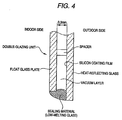
- a double-glazing unit which comprises two glass plates disposed so as to face each other and separated by an air layer, inert gas layer or vacuum layer formed by sealing the edges of the glass plates, at least one of the glass plates comprising the above-described heat-reflecting glass.
- a preferred embodiment of the above double-glazing unit is that the heat-reflecting glass is used as an outdoor-side glass plate, and the coating film formed on a surface of the heat-reflecting glass faces the air, inert gas or vacuum layer.
- low visible light reflectivity is realized by using a regulated film constitution while utilizing the high infrared-shielding and insulating properties of silicon, and highly durable glasses are obtained by forming the coating film by a pyrolytic method.
- the present invention is characterized in that glasses which are excellent in infrared-shielding properties and appearance and respectively give greenish, bronzy and grayish reflected color tones can be realized by regulating the coloring components of the substrate glass.
- a double-glazing unit having higher heat-shielding performance is obtained by applying any of these heat-reflecting glasses to a double-glazing unit structure.
- an heat-reflecting glass which has such low visible light reflectivity that its visible light reflectance is 25% or lower, preferably 20% or lower, in the case of giving a greenish reflected color tone, and is 15% or lower in the case of giving a bronzy or grayish reflected color tone.
- this heat-reflecting glass as at least one of the glass plates of a double-glazing unit, higher solar heat shielding performance can be imparted to the double-glazing unit.
- the glass substrates for use in the present invention are made of a glass which comprises basic glass compositions for a soda-lime silicate glass and coloring components.
- the glass substrate is intended to have a greenish tone
- the glass contains, as the coloring components, from 0.40 to 1.30 wt% total iron oxide in terms of Fe 2 O 3 , wherein the amount of FeO in terms of Fe 2 O 3 is from 20 to 35 wt% of the total iron oxide amount in terms of Fe 2 O 3 , from 0 to 0.85 wt% TiO 2 , and from 0 to 20 ppm CoO.
- the glass substrate contains, as the coloring components, from 0.15 to 0.25 wt% total iron oxide in terms of Fe 2 O 3 , wherein the amount of FeO in terms of Fe 2 O 3 is from 20 to 30 wt% of the total iron oxide amount in terms of Fe 2 O 3 , from 8 to 25 ppm Se, and from 12 to 50 ppm CoO.
- the glass substrate is intended to have a grayish tone
- the glass contains, as the coloring components, from 0.15 to 0.25 wt% total iron oxide in terms of Fe 2 O 3 , wherein the amount of FeO in terms of Fe 2 O 3 is from 20 to 30 wt% of the total iron oxide amount in terms of Fe 2 O 3 , from 5 to 23 ppm Se, and from 14 to 60 ppm CoO.
- SiO 2 is the main component forming a glass skeleton. If the content of SiO 2 is lower than 65%, the glass has reduced durability. If the content thereof exceeds 80%, the glass is difficult to melt. Consequently, the content of SiO 2 should be from 65 to 80%.
- Al 2 O 3 which is not an essential ingredient, serves to improve the durability of the glass. If the content of Al 2 O 3 exceeds 5%, the glass is difficult to melt. Consequently, the content of Al 2 O 3 should be 5% or lower, and is preferably from 0.1 to 2%.
- B 2 O 3 which is not an essential ingredient, is used for improving the durability of the glass and also as a melting aid. If the content thereof exceeds 5%, troubles arise in glass forming due to vaporization of B 2 O 3 , etc. Consequently, the content of B 2 O 3 should be 5% or lower.
- MgO and CaO are used for improving the durability of the glass and for regulating the devitrification temperature and viscosity of the glass during molding. If the content of MgO, which is not an essential ingredient, exceeds 10%, the glass has an elevated devitrification temperature. Consequently, the content of MgO should be 10% or lower. If the content of CaO is lower than 5% or exceeds 15%, the glass has an elevated devitrification temperature. Consequently the content of CaO should be from 5 to 15%. Furthermore, if the total content of MgO and CaO is lower than 5%, the glass has reduced durability. If the total content thereof exceeds 15%, the glass has an elevated devitrification temperature. Consequently, the total content of MgO and CaO should be from 5 to 15%.
- Na 2 O and K 2 O are used as glass melting accelerators. If the content of Na 2 O is lower than 10% or if the total content of Na 2 O and K 2 O is lower than 10%, the effect of melting acceleration is poor. If the content of Na 2 O exceeds 18% or if the total content of Na 2 O and K 2 O exceeds 20%, the glass has reduced durability. Therefore, the content of Na 2 O should be from 10 to 18%, and the total content of Na 2 O and K 2 O should be 10 to 20%.
- the proportion of K 2 O, which is not an essential ingredient, should be 5% or lower because it necessitates a higher material cost than Na 2 O.
- iron oxide is present in the forms of Fe 2 O 3 and FeO. If the total iron oxide content in terms of Fe 2 O 3 is below 0.15%, the effect of absorbing ultraviolet and infrared rays is low and a high visible light transmittance results. On the other hand, total contents thereof exceeding 1.30% are undesirable in that during melting, an upper part of the molten glass heats up excessively due to the heat-absorbing effect of FeO, leading to a fear that the resulting radiant heat may raise the temperature of the ceiling bricks of the melting furnace to a temperature above the heat-resistant temperature thereof and the ceiling bricks may thus begin to melt. Consequently, the total iron oxide content in terms of Fe 2 O 3 should be from 0.15 to 1.30%.
- the total iron oxide content in terms of Fe 2 O 3 for respective glass plate colors is preferably from 0.40 to 1.30%, that for a bronzy tone is preferably from 0.15 to 0.25% and that for a grayish tone is preferably from 0.15 to 0.25%.
- the ratio of (the amount of FeO in terms of Fe 2 O 3 ) to (the amount of total iron oxide in terms of Fe 2 O 3 ) is preferably regulated to 0.2 to 0.35 for a greenish tone and 0.2 to 0.3 for a bronzy tone and a grayish tone while maintaining the total iron oxide content within the above range.
- Values of that ratio exceeding 0.35 are undesirable in that the absolute amount of FeO is too large and the temperature of ceiling bricks of the glass melting furnace increases excessively.
- values of that ratio smaller than 0.2 are undesirable in that the glass has a reduced heat absorbing effect.
- TiO 2 in the glass is an ingredient which absorbs ultraviolet rays, although not essential. It further absorbs visible light and thus functions to reduce visible light reflectance. It is therefore preferred to add TiO 2 as a coloring ingredient especially for greenish glasses. However, if the concentration of TiO 2 exceeds 0.85%, the glass excessively absorbs visible rays having shorter wavelengths and hence has not the desired color tone but a yellowish tone. Consequently, the content of TiO 2 in the glass composition for use in the present invention should be 0.85% or lower.
- CoO contributes to obtaining a greenish color tone when coexistent with TiO 2 and further serves to reduce visible light transmittance.
- the color of the glass changes from green to yellowish green or yellow as the addition amount of TiO 2 increases. This color change of the glass toward yellow by the addition of TiO 2 can be inhibited by adding CoO.
- CoO concentrations exceeding 20 ppm are undesirable in that the glass changes to a bluish tone. Consequently, the concentration of CoO for obtaining a greenish tone should be 0 to 20 ppm.
- CoO is an ingredient which, when coexistent with Se, serves to impart a bronzy to grayish tone.
- the content of CoO is preferably from 12 to 50 ppm for obtaining a bronzy tone and from 14 to 60 ppm for obtaining a grayish tone. If the content of CoO is lower than each lower limit, the desired color tone cannot be obtained. If the content thereof exceeds each upper limit, the glass plate has an excessively reduced visible light transmittance.
- Se is an ingredient for obtaining a bronzy or grayish tone due to its pink coloration in combination with the complementary color of CoO.
- the content of Se is preferably from 8 to 25 ppm for obtaining a bronzy tone and from 5 to 23 ppm for obtaining a grayish tone. If the content of Se is lower than each lower limit, the desired color tone cannot be obtained. If the content thereof exceeds each upper limit, the glass plate has an excessively reduced visible light transmittance.
- the glass having a composition within the range according to the present invention may contain NiO and Cr 2 O 3 for the purpose of color tone regulation and may further contain CeO 2 as an ultraviolet absorbing ingredient.
- NiO is an ingredient for obtaining a grayish color tone.
- too high NiO concentrations result in a reduced visible light transmittance. Consequently, the content of NiO is preferably up to 0.005%.
- Cr 2 O 3 is an ingredient for obtaining a greenish color tone.
- the content of Cr 2 O 3 is preferably up to 0.5%, more preferably up to 0.05%.
- CeO 2 is an ultraviolet absorbing ingredient.
- CeO 2 concentrations exceeding 1.0% are undesirable in that the class excessively absorbs visible rays having shorter wavelengths and hence has not the desired greenish tone but a yellowish tone, and that particularly in a bronzy or grayish tone glass, coloration efficiency of Se tends to lower due to oxidation force of CeO 2 , thereby making it difficult to obtain the desired tone.
- high CeO 2 concentrations increase the cost of glass production. Consequently, the content of CeO 2 is preferably up to 1.0%.
- the glass having a composition within the range according to the present invention may contain at least one of ZnO, MnO, V 2 O 5 , and MoO 3 in a total amount of up to 1% and sulfur in an amount of up to 1% in terms of SO 3 , as long as these ingredients are not counter to the spirit of the invention.
- ZnO has the effect of preventing the generation of nickel sulfide, which is apt to generate during glass melting in a reducing atmosphere and is causative of spontaneous breakage.
- MnO, V 2 O 5 , and MoO 3 in the glass each serves as an ultraviolet absorbing ingredient. They can be used also for the fine control of a bronze to neutral grayish tone according to their degree of ultraviolet absorption.
- SO 3 is an ingredient which comes into the glass mainly from a sulfuric acid salt or the like used as a refining agent. When added in a proper amount, SO 3 accelerates the melting and refining of the glass.
- the infrared-shielding performance of each of the glass substrates respectively having the compositions described above is enhanced by forming thereon a coating film mainly comprising silicon.
- the thickness of the silicon coating film in the present invention is determined according to the desired infrared-shielding performance attributable to visible light reflection and the desired color tone of reflected light and reflectance with respect to light incident from the uncoated side of the glass plate.
- the preferred range of the thickness thereof is from 10 to 50 nm.
- the reflectance of the glass plate with respect to light incident thereon from the uncoated side thereof can be reduced by forming, between the glass plate and the silicon coating film, a thin film having a refractive index of from 1.8 to 2.6, which is an intermediate refractive index between that of the soda-lime glass and that of silicon, in a thickness of from 20 to 120 nm; forming a thin film having a refractive index of from 1.45 to 2.6 and a thickness of from 10 to 100 nm on the silicon coating film; or forming the film having a refractive index of from 1.8 to 2.6 and a thickness of from 20 to 120 between the glass plate and the silicon coating film and then forming the thin film having a refractive index of from 1.45 to 2.6 and a thickness of from 10 to 100 nm on the silicon coating film.
- Examples of the material of the thin film having a refractive index of from 1.8 to 2.6, which is an intermediate refractive index between that of the soda-lime glass and that of silicon, formed between the glass plate and the silicon coating film include tin oxide, indium oxide, zinc oxide and titanium oxide. It is, however, preferred to use tin oxide or titanium oxide form the standpoints of transparency, durability, ease of film deposition by CVD, which is a preferred film deposition technique as will be explained later, and the availability of appropriate raw materials.
- the thickness of the thin film formed between the glass plate and the silicon coating film varies depending on the refractive index of the thin and the desired color of reflected light.
- the preferred range of the film thickness in the case of using tin oxide is from 40 to 120 nm, while that in the case of using titanium oxide is from 20 to 50 nm.
- silicon oxide may be deposited to form an alkali barrier layer as long as this barrier layer does not adversely influence optical properties including reflectance and transmittance.
- This silicon oxide layer preferably has a thickness in the range of about from 10 to 30 nm.
- Examples of the material of the thin film having a refractive index of from 1.45 to 2.6 and a thickness of from 10 to 100 nm formed on the silicon coating film include silicon oxide, silicon oxide containing carbon and nitrogen, aluminum oxide, an oxide of metals mainly comprising silicon and aluminum, tin oxide, titanium oxide, zinc oxide and indium oxide.
- silicon oxide, silicon oxide containing carbon and nitrogen, tin oxide, and titanium oxide it is preferred to use any one of silicon oxide, silicon oxide containing carbon and nitrogen, tin oxide, and titanium oxide.
- the kind of thin film to be formed depends on the film constitution and the refractive index of the thin film.
- this coating film is preferably made of tin oxide, silicon oxide, or titanium oxide.
- this coating film is desirably made of silicon oxide.
- the thickness of the thin film directly formed on the silicon coating film is preferably in the range of from 10 to 70 nm in the case of tin oxide, from 40 to 100 nm in the case of silicon oxide, and from 10 to 50 nm in the case of titanium oxide.
- the thickness of the silicon oxide film formed on the tin oxide or titanium oxide film formed on the silicon coating film is preferably in the range of from 40 to 100 nm.
- the oxide thin film directly formed on the silicon coating film serves not only to prevent the oxidation of the silicon coating film and improve the durability thereof but also to prevent the silicon coating film from being deteriorated by alkali ingredients released from the glass.
- the oxide thin film directly coated on the silicon coating film may comprise two or more layers
- film constitutions suitable for achieving these purposes include glass/tin oxide/silicon/tin oxide, glass/tin oxide/silicon/silicon oxide, glass/tin oxide/silicon/titanium oxide, glass/tin oxide/silicon/silicon oxide/tin oxide, glass/titanium oxide/silicon/silicon oxide/tin oxide, glass/silicon/silicon oxide/tin oxide/silicon oxide, glass/silicon oxide/silicon oxide/tin oxide/silicon oxide, and glass/tin oxide/silicon/tin oxide/silicon oxide.
- Tin oxide can give an electroconductive film when deposited so as to contain fluorine or antimony and in a thickness of about 150 nm or larger. However, there is no need of adding these elements since an important factor in the above application is the refractive index of the coating film. Because of this and because the thickness of the tin oxide thin film is 120 nm or smaller in the present invention, the glass having this coating film does not show electrical conductivity which may exert an adverse influence on electromagnetic wave transmittance.
- the heat-reflecting glasses of the present invention if the visible light reflectance of the glass plate, with respect to light incident thereon from the uncoated side thereof, exceeds 25% as a result of the formation of the coating films, the reflected light glitters to constitute a nuisance to the neighborhood. Consequently, the visible light reflectance of the heat-reflecting glasses as measured on the uncoated side of the glass plate is 25% or lower, although the heat-reflecting glasses can have a reduced visible light reflectance with respect to light incident thereon from the uncoated side of the glass plate due to the formation of the coating films, the reflection of visible light can occur on the uncoated surface of the glass plate irrespective of the color tone of the glass. Specifically, the visible light reflectance on the uncoated-side surface of the glass plate is 4% at the most.
- the heat-reflecting glasses having different color tones of the present invention each has a visible light reflectance of 25% or lower with respect to light incident thereon from the uncoated side of the glass plate, they are inhibited from causing a reflected-light nuisance to the neighborhood, while showing heat radiation shielding performance.
- Examples of methods for forming those thin films include physical methods such as vapor deposition in which metals or metal oxides are used, sputtering, and ion plating and chemical methods such as chemical vapor deposition (CVD) in which a gaseous metal compound is blown against a heated glass substrate to form a film, a spraying method in which droplets of a solution of a metal compound are blown against a heated glass plate, and a powder spraying method in which a powder comprising a metal compound is sprayed.
- physical methods such as vapor deposition in which metals or metal oxides are used, sputtering, and ion plating
- chemical methods such as chemical vapor deposition (CVD) in which a gaseous metal compound is blown against a heated glass substrate to form a film
- CVD chemical vapor deposition
- spraying method in which droplets of a solution of a metal compound are blown against a heated glass plate
- a powder spraying method in which a powder comprising a
- the physical film deposition methods have a problem that a highly durable coating film is difficult to obtain although the methods are excellent in evenness of film thickness. Furthermore, the physical methods are less suitable for mass production because they necessitate a procedure in which cut glass plates are washed and then subjected to film deposition in a vacuum apparatus. The chemical methods are superior also in suitability for size increase in glass substrates.
- the spraying method has a drawback that itis difficult to obtain a coating film of a material which is not an oxide, as in the case of forming a silicon film in the present invention, although it has an advantage that film deposition can be conducted at low cost because of the simplicity of the method.
- Another drawback of the spraying method is that evenness of film thickness is difficult to obtain because the control of sprayed droplets and the control of reaction products and products to be discharged, including undecomposed products, are difficult.
- use of the spraying method results in considerable glass distortion. Therefore, CVD is preferred from a comprehensive standpoint.
- a general technique for forming a film of a metal oxide by CVD comprises heating a cut glass and blowing a gaseous compound of the metal against the glass to deposit a metal oxide film thereon.
- a gaseous compound of the metal against the glass to deposit a metal oxide film thereon.
- Film deposition may also be conducted in such a manner that a silicon coating film or the like is formed by CVD and a coating film of a metal oxide, e.g., tin oxide or titanium oxide, is formed thereon by the spraying method.
- a metal oxide e.g., tin oxide or titanium oxide
- silicon materials for a silicon coating film to be formed by CVD include monosilane, disilane, trisilane, monochlorosilane, dichlorosilane, 1,2-dimethylsilane, 1,1,2-trimethyldisilane, and 1,1,2;2-tetramethyldisilane.
- a gas of an unsaturated hydrocarbon such as, e.g., ethylene, acetylene, or toluene may be added for the purposes of improving the alkali resistance of the silicon coating film and regulating the refractive index of the film.
- Examples of silicon materials for silicon oxide to be deposited by CVD include monosilane, disilane, trisilane, monochlorosilane, dichlorosilane, 1,2-dimethylsilane, 1,1,2-trimethyldisilane, and 1,1,2,2-tetramethyldisilane.
- Examples of oxidizing agents include oxygen, water vapor, dry air, carbon dioxide, carbon monoxide, and nitrogen dioxide.
- a gas of an unsaturated hydrocarbon such as, e.g., ethylene, acetylene, or toluene may be added for the purposes of preventing a silane used as a silicon material from oxidizing before it reaches the glass surface, and of regulating the refractive index of the silicon oxide film to be obtained.
- Examples of aluminum materials for aluminum oxide include trimethylaluminum, aluminum triisopropoxide, diethylaluminum chloride, aluminum acetylacetonate, and aluminum chloride.
- titanium materials for titanium oxide to be deposited by CVD include titanium tetrachloride and titanium isopropoxide.
- Examples of tin compound materials usable in CVD include tin tetrachloride, dimethyltin dichloride, dibutyltin dichloride, tetrabutyltin, tetramethyltin, dioctyltin dichloride, and monobutyltin trichloride.
- Examples of oxidizing agents for obtaining tin oxide include oxygen, water vapor, and dry air. Fluorine, antimony, or the like may be incorporated into the tin oxide as long as these additive ingredients do not excessively increase the electrical conductivity of the tin oxide.
- fluorine materials for use in the fluorine incorporation include hydrogen fluoride, trifluoroacetic acid, bromotrifluoromethane, and chlorodifluoromethane.
- antimony materials for use in the antimony incorporation include antimony pentachloride and antimony trichloride.
- titanium materials usable in the spraying method include titanium tetrachloride, titanium tetraethoxide, acetylacetone titanyl, titanous sulfate, titanic sulfate, titanium tetrabutoxide, titanium isopropoxide, titanium methoxide, titanium diisopropoxybisoctylene glycoxide, titanium di-n-propoxybisoctylene glycoxide, titanium (diisopropoxymonooctylene glycoxy)acetylacetonate, titanium (di-n-butoxymonooctylene glycoxy)acetylacetonate, titanium tetraoctylene glycoxide, and titanium di-n-propoxybisacetylacetonate.
- tin materials usable in the spraying method include tin tetrachloride, dibutyltin dichloride, tetrabutyltin, dioctyltin dichloride, dimethyltin dichloride, tetraoctyltin, dibutyltin oxide, dibutyltin dilaurate, dibutyltin fatty acids, monobutyltin fatty acids, monobutyltin trichloride, dibutyltin diacetate, dioctyltin diacetate, and dioctyltin dilaurate.
- Such optional elements include silicon, aluminum, zinc, copper, indium, bismuth, gallium, boron, vanadium, manganese, zirconium, cobalt, iron, chromium, nickel, copper, antimony, and zirconium.
- the double-glazing unit include one in which the two glass plates are disposed apart at a distance of about from 5 to 6 mm to form therebetween an air layer or a layer of an inert gas, e.g., argon, and further include one in which the two glass plates are disposed apart at a distance of 1 mm or shorter to form therebetween a vacuum layer having a pressure of from 10 -2 to 10 -4 Torr.
- an inert gas e.g., argon
- this double-glazing unit is preferably fabricated in such a manner that at least the outer-side glass plate is the heat-reflecting glass and that the at least one silicon coating film formed on one surface of the heat-reflecting glass faces the air layer, layer of an inert gas, e.g., argon, or vacuum layer.
- an inert gas e.g., argon
- solar energy is absorbed by the heat-reflecting glass, disposed as the outer-side glass plate, which uses a glass substrate containing iron which has been regulated with respect to amount and valence.
- the absorbed solar energy is shielded by the at least one silicon coating film formed on that side of the heat-reflecting glass which faces the air layer, layer of an inert gas, e.g., argon, or vacuum layer.
- the air layer, layer of an inert gas, e.g., argon, or vacuum layer formed between the heat-reflecting glass and the indoor-side glass plate reduces the transmittance of the solar energy.
- the inflow of solar energy into the room is inhibited.
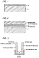
- Fig. 1 is an enlarged sectional view of a heat-reflecting glass according to the present invention.
- This heat-reflecting glass comprises a glass plate 1 and a silicon film 2 formed on one of two main surfaces thereof.
- Fig. 2 is an enlarged sectional view of a heat-reflecting glass obtained in Example 1.
- This heat-reflecting glass comprises a glass plate 1, a tin oxide thin film formed on one of two main surface of the glass plate 1, a silicon coating film 2 formed on the tin oxide coating film, an silicon oxide thin film formed on the silicon thin film and a tin oxide thin film formed on the silicon oxide thin film.
- Ferric oxide, cobalt oxide and a carbonaceous reducing agent were suitably mixed with typical soda-lime silicate glass batch materials. This batch was melted by heating to 1,500°C in an electric furnace. The batch was kept molten for 4 hours, and the resulting molten glass was cast on a stainless-steel plate and annealed to obtain a green glass plate having a thickness of about 8mm. This glass plate was polished so as to have a thickness of 6 mm.
- this glass plate was washed and dried.
- the dried glass plate was placed on the mesh belt of an open type conveying furnace and passed through a heating furnace to heat it to about 570°C.
- a heating furnace to heat it to about 570°C.
- This heated glass plate was formed a tin oxide coating film using a mixed gas composed of monobutyltin trichloride gas, oxygen, water vapor and nitrogen.
- This coated glass was placed in a closed type furnace. The furnace was evacuated with a vacuum pump and the chamber was then filled with nitrogen, during which operation the glass plate was heated to about 600°C. Thereafter, a gas composed of monosilane and ethylene was used to form a silicon coating film, and the coated glass plate was cooled gradually.
- the open type conveying furnace was used again to heat the glass plate to about 570°C. During this heating, the silicon surface was oxidized to give silicon oxide. Thereafter, a mixed gas composed of monobutyltin trichloride gas, oxygen, water vapor and nitrogen was used to form a tin oxide coating film.
- a glass plate having a thickness of 6 mm was obtained in the same manner as in Example 1.
- This glass plate was washed and dried.
- the dried glass plate was placed on the mesh belt of an open type conveying furnace and passed through a heating furnace to heat it to about 570°C.
- On this heated glass plate was formed a titanium oxide coating film using a mixed gas composed off titanium isopropoxide gas, oxygen and nitrogen.
- this coated glass plate was placed in a closed type furnace.
- the furnace was evacuated with a vacuum pump and the chamber was then filled with nitrogen, during which operation the glass plate was heated to about 600°C.
- a gas composed of monosilane and ethylene was used to form a silicon coating film, and the coated glass plate was cooled gradually.
- the open type conveying furnace was used again to heat the glass plate to about 570°C. During this heating, the silicon surface was oxidized to give silicon oxide Thereafter, a mixed gas composed of monobutyltin trichloride gas, oxygen, water vapor and nitrogen was used to form a tin oxide coating film.
- a glass plate having a thickness of 6 mm was obtained in the same manner as in Example 1.
- This glass plate was washed, dried and then placed in a closed type furnace.
- the furnace was evacuated with a vacuum pump and the chamber was then filled with nitrogen, during which operation the glass plate was heated to about 600°C. Thereafter, a gas composed of monosilane and ethylene was used to form a silicon coating film, and the coated glass plate was cooled gradually.
- An open type conveying furnace was used to heat the coated glass plate to about 570°C. During this heating, the silicon surface was oxidized to give silicon oxide. Thereafter, a mixed gas composed of monobutyltin trichloride gas, oxygen, water vapor and nitrogen was used to form a tin oxide coating film.
- the open type conveying furnace was used again to heat this glass plate to about 570°C, and a mixed gas composed of monosilane, oxygen and nitrogen was used to form a silicon oxide coating film.
- a glass plate having a thickness of 6 mm was obtained in the same manner as in Example 1.
- This glass plate was washed and dried.
- the dried glass plate was placed on the mesh belt of an open type conveying furnace and passed through a heating furnace to heat it to about 570°C.
- On this heated glass plate was formed a tin oxide coating film using a mixed gas composed of monobutyltin trichloride gas, oxygen, water vapor and nitrogen.
- this coated glass plate was placed in a closed type furnace.
- the furnace was evacuated with a vacuum pump and the chamber was then filled with nitrogen, during which operation the glass plate was heated to about 600°C.
- a gas composed of monosilane and ethylene was used to form a silicon coating film.
- the furnace was then evacuated again with a vacuum pump and the chamber was filled with nitrogen.
- the coated glass plate was heated to about 570°C, and a mixed gas composed of monobutyltin trichloride gas, oxygen, water vapor and nitrogen was used to form a tin oxide coating film.
- a glass plate having a thickness of 6 mm was obtained in the same manner as in Example 1.
- This glass plate was washed and dried.
- the dried glass plate was placed on the mesh belt of an open type conveying furnace and passed through a heating furnace to heat it to about 570°C.
- On this heated glass plate was formed a tin oxide coating film using a mixed gas composed of monobutyltin trichloride gas, oxygen, water vapor and nitrogen.
- this coated glass plate was placed in a closed type furnace.
- the furnace was evacuated with a vacuum pump and the chamber was then filled with nitrogen, during which operation the glass plate was heated to about 600°C.
- a gas composed of monosilane and ethylene was used to form a silicon coating film.
- the furnace was then evacuated again with a vacuum pump and the chamber was filled with nitrogen.
- the coated glass plate was heated to about 570°C, and a mixed gas composed of monosilane, ethylene, oxygen and nitrogen was used to form a silicon oxide coating film.
- a glass plate having a thickness of 6 mm was obtained in the same manner as in Example 1.
- This glass plate was washed and dried.
- the dried glass plate was placed on the mesh belt of an open type conveying furnace and passed through a heating furnace to heat it to about 570°C.
- On this heated glass plate was formed a tin oxide coating film using a mixed gas composed of monobutyltin trichloride gas, oxygen, water vapor and nitrogen.
- this coated glass plate was placed in a closed type furnace.
- the furnace was evacuated with a vacuum pump and the chamber was then filled with nitrogen, during which operation the glass plate was heated to about 600°C.
- a gas composed of monosilane and ethylene was used to form a silicon coating film.
- the furnace was then evacuated again with a vacuum pump and the chamber was filled with nitrogen.
- the coated glass plate was heated to about 570°C, and a mixed gas composed of monobutyltin trichloride gas, oxygen, water vapor and nitrogen was used to form a tin oxide coating film.
- the furnace was evacuated again with a vacuum pump and the chamber was filled with nitrogen.
- the glass was heated to about 570°C, and a mixed gas composed of monosilane, ethylene, oxygen, and nitrogen was used to form a silicon oxide coating film.
- Ferric oxide and a carbonaceous reducing agent were suitably mixed with typical soda-lime silicate glass batch materials. This batch was melted by heating to 1,500°C in an electric furnace. The batch was kept molten for 4 hours, and the resulting molten glass was cast on a stainless-steel plate and annealed to obtain a green glass plate having a thickness of about 8 mm. This glass plate was polished so as to have a thickness of 6 mm.
- this glass plate was washed and dried, and was then coated in the same manner as in Example 7.
- Ferric oxide, titanium oxide and a carbonaceous reducing agent were suitably mixed with typical soda-lime silicate glass batch materials. This batch was melted by heating to 1,500°C in an electric furnace. The batch was kept molten for 4 hours, and the resulting molten glass was cast on a stainless-steel plate and annealed to obtain a green glass plate having a thickness of about 8mm. This glass plate was polished so as to have a thickness of 6 mm.
- this glass plate was washed and dried, and was then coated in the same manner as in Example 7.
- Ferric oxide, selenium metal, cobalt oxide and a carbonaceous reducing agent were suitably mixed with typical soda-lime silicate glass batch materials. This batch was melted by heating to 1,500°C in an electric furnace. The batch was kept molten for 4 hours, and the resulting molten glass was cast on a stainless-steel plate and annealed to obtain a bronze glass plate having a thickness of about 8 mm. This glass plate was polished so as to have a thickness of 6 mm.
- this glass plate was washed and dried, and was then coated in the same manner as in Example 1.
- Ferric oxide, Selenium metal, cobalt oxide and a carbonaceous reducing agent were suitably mixed with typical soda-lime silicate glass batch materials. This batch was melted by heating to 1,500°C in an electric furnace. The batch was kept molten for 4 hours, and the resulting molten glass was cast on a stainless-steel plate and annealed to obtain a gray glass plate having a thickness of about 8 mm. This glass plate was polished so as to have a thickness of 6 mm.
- this glass plate was washed and dried, and was then coated in the same manner as in Example 7.
- Ferric oxide, cobalt oxide and a carbonaceous reducing agent were suitably mixed with typical soda-lime silicate glass batch materials. This batch was melted by heating to 1,500°C in an electric furnace. The batch was kept molten for 4 hours, and the resulting molten glass was cast on a stainless-steel plate and annealed to obtain a green glass plate having a thickness of about 8mm. This glass plate was polished so as to have a thickness of 6 mm.
- this glass plate was washed, dried and then placed in a closed type furnace.
- the furnace was evacuated with a vacuum pump and the chamber was then filled with nitrogen, during which operation the glass plate was heated to about 600°C.
- a gas composed of monosilane and ethylene was used to form a silicon coating film, and the coated glass plate was cooled gradually.
- An open type conveying furnace was used to heat the glass plate again to about 570°C. During this heating, the silicon surface was oxidized to give silicon oxide. Thereafter, a mixed gas composed of monobutyltin trichloride gas, oxygen, water vapor and nitrogen was used to form a tin oxide coating film.
- Ferric oxide, cobalt oxide and a carbonaceous reducing agent were suitably mixed with typical soda-lime silicate glass batch materials. This batch was melted by heating to 1,500°C in an electric furnace. The batch was kept molten for 4 hours, and the resulting molten glass was cast on a stainless-steel plate and annealed to obtain a green glass plate having a thickness of about 8 mm. This glass plate was polished so as to have a thickness of 6 mm.
- this glass plate was washed, dried and then placed in a closed type furnace.
- the furnace was evacuated with a vacuum pump and the chamber was then filled with nitrogen, during which operation the glass plate was heated to about 600°C.
- a gas composed of monosilane and ethylene was used to form a silicon coating film, and the coated glass plate was cooled gradually.
- the furnace was then evacuated again with a vacuum pump and the chamber was filled with nitrogen.
- the coated glass plate was heated to about 570°C and a mixed gas composed of monobutyl tin trichloride gas, oxygen, water vapor and nitrogen was used to form a tin oxide coating film.
- Ferric oxide, cobalt oxide and a carbonaceous reducing agent were suitably mixed with typical soda-lime silicate glass batch materials. This batch was melted by heating to 1,500°C in an electric furnace. The batch was kept molten for 4 hours, and the resulting molten glass was cast on a stainless-steel plate and annealed to obtain a green glass plate having a thickness of about 8mm. This glass plate was polished so as to have a thickness of 6 mm.
- this glass plate was washed, dried and then placed in a closed type furnace.
- the furnace was evacuated with a vacuum pump and the chamber was then filled with nitrogen, during which operation the glass plate was heated to about 600°C.
- a gas composed of monosilane and ethylene was used to form a silicon coating film, and the coated glass plate was cooled gradually.
- the furnace was then evacuated again with a vacuum pump and the chamber was filled with nitrogen.
- the coated glass plate was heated to about 570°C, and a mixed gas composed of monosilane, ethylene, oxygen and nitrogen was used to form a silicon oxide coating film.
- a double-glazing unit was fabricated using the heat-reflecting glass obtained in Example 6 and a 6 mm thick glass plate made of a colorless and transparent soda-lime glass.
- aluminum spacers packed with a drying agent were disposed between the two glass plates along the edges thereof, and these glass plates and spacers wore bonded to each other with butyl rubber.
- the coated side of the heat-reflecting glass faced the air layer, which had a thickness of 6 mm.
- the double-glazing unit obtained had a visible light transmittance of 37.3% and a visible light reflectance of 19.7%, gave a greenish reflected color tone, and had a solar heat gain coefficient of 0.35.
- a double-glazing unit was fabricated in the same manner as in Example 14 using the heat-reflecting glass obtained in Example 11 and a 6 mm-thick glass plate made of a colorless and transparent soda-lime glass.
- the double-glazing unit obtained had a visible light transmittance of 37.7% and a visible light reflectance of 12.3%, gave a greenish reflected color tone, and had a solar heat gain coefficient of 0.31. These properties were obtained through examinations of the pane from the coated-glass side. These optical properties were measured in the same manner as in Example 1.
- heat-reflecting glasses are obtained according to the present invention which have a low visible light reflectance so as not to arouse troubles such as a reflected-light nuisance to the neighborhood, have high heat radiation shielding performance, and do not exert an adverse influence on electromagnetic wave transmission, and which, when viewed from their uncoated side, respectively give reflected lights of beautiful greenish, bronzy and grayish tones.
- a double-glazing unit having higher heat radiation shielding performance is obtained by applying any of these heat-reflecting glasses to a double-glazing unit structure.
Landscapes
- Chemical & Material Sciences (AREA)
- Life Sciences & Earth Sciences (AREA)
- Engineering & Computer Science (AREA)
- Chemical Kinetics & Catalysis (AREA)
- General Chemical & Material Sciences (AREA)
- Geochemistry & Mineralogy (AREA)
- Materials Engineering (AREA)
- Organic Chemistry (AREA)
- Surface Treatment Of Glass (AREA)
- Glass Compositions (AREA)
- Joining Of Glass To Other Materials (AREA)
Applications Claiming Priority (2)
| Application Number | Priority Date | Filing Date | Title |
|---|---|---|---|
| JP33406998 | 1998-11-25 | ||
| JP10334069A JP2000159546A (ja) | 1998-11-25 | 1998-11-25 | 熱線反射ガラス及びこれを用いた複層ガラス |
Publications (1)
| Publication Number | Publication Date |
|---|---|
| EP1004550A1 true EP1004550A1 (fr) | 2000-05-31 |
Family
ID=18273173
Family Applications (1)
| Application Number | Title | Priority Date | Filing Date |
|---|---|---|---|
| EP99123220A Withdrawn EP1004550A1 (fr) | 1998-11-25 | 1999-11-25 | Verre réfléchissant la chaleur et fenêtre à double vitrage avec ce verre |
Country Status (3)
| Country | Link |
|---|---|
| EP (1) | EP1004550A1 (fr) |
| JP (1) | JP2000159546A (fr) |
| CA (1) | CA2290276A1 (fr) |
Cited By (5)
| Publication number | Priority date | Publication date | Assignee | Title |
|---|---|---|---|---|
| WO2001016041A1 (fr) * | 1999-08-31 | 2001-03-08 | Nippon Sheet Glass Co., Ltd. | Feuille de verre transparente protegeant de la chaleur et unite a multiple vitrage dans laquelle est utilisee ladite feuille de verre |
| WO2003073055A1 (fr) * | 2002-02-28 | 2003-09-04 | Shin-Etsu Handotai Co., Ltd. | Systeme de mesure de la temperature, dispositif de chauffage utilisant le systeme, procede de production d'une plaquette a semi-conducteurs, element translucide de protection contre les rayons calorifiques, element reflechissant la lumiere visible, miroir reflechissant utilisant un systeme d'exposition, dispositif a semi-co |
| GB2403731A (en) * | 2003-07-11 | 2005-01-12 | Pilkington Plc | Solar control glazing |
| WO2005007592A3 (fr) * | 2003-07-11 | 2005-08-25 | Pilkington Plc | Vitrage solaire |
| WO2007112426A2 (fr) * | 2006-03-28 | 2007-10-04 | Ppg Industries Ohio, Inc. | verre bleu de faible absorbance solaire, verre bleu avec revêtement réfléchissant solaire, et unité isolante de faible gain thermique solaire |
Families Citing this family (3)
| Publication number | Priority date | Publication date | Assignee | Title |
|---|---|---|---|---|
| JP5433123B2 (ja) * | 2000-09-14 | 2014-03-05 | 旭硝子株式会社 | 合わせガラス |
| EP1671783A1 (fr) * | 2000-09-14 | 2006-06-21 | Asahi Glass Company, Limited | Vitrage feuilleté |
| CN107667011A (zh) * | 2015-06-03 | 2018-02-06 | 美国圣戈班性能塑料公司 | 太阳能控制膜 |
Citations (6)
| Publication number | Priority date | Publication date | Assignee | Title |
|---|---|---|---|---|
| US4019887A (en) * | 1974-06-14 | 1977-04-26 | Pilkington Brothers Limited | Method for coating glass |
| EP0343628A2 (fr) * | 1988-05-24 | 1989-11-29 | Asahi Glass Company Ltd. | Procédé de fabrication d'un substrat en verre pour une cellule solaire |
| EP0616883A2 (fr) * | 1988-07-27 | 1994-09-28 | Saint-Gobain Vitrage International | Vitrage à couche électroconductrice obtenue par pyrolyse de composés en poudre, utilisable en tant que pare-brise pour automobile |
| DE19636301A1 (de) * | 1995-09-06 | 1997-03-13 | Glaverbel | Sehr dunkelgraues Natronkalkglas |
| WO1998020524A1 (fr) * | 1996-11-06 | 1998-05-14 | Pacific Solar Pty. Limited | Formation d'un film cristallin semi-conducteur sur un substrat de verre |
| JPH10152347A (ja) * | 1996-11-20 | 1998-06-09 | Nippon Sheet Glass Co Ltd | 複層ガラス |
-
1998
- 1998-11-25 JP JP10334069A patent/JP2000159546A/ja active Pending
-
1999
- 1999-11-24 CA CA 2290276 patent/CA2290276A1/fr not_active Abandoned
- 1999-11-25 EP EP99123220A patent/EP1004550A1/fr not_active Withdrawn
Patent Citations (6)
| Publication number | Priority date | Publication date | Assignee | Title |
|---|---|---|---|---|
| US4019887A (en) * | 1974-06-14 | 1977-04-26 | Pilkington Brothers Limited | Method for coating glass |
| EP0343628A2 (fr) * | 1988-05-24 | 1989-11-29 | Asahi Glass Company Ltd. | Procédé de fabrication d'un substrat en verre pour une cellule solaire |
| EP0616883A2 (fr) * | 1988-07-27 | 1994-09-28 | Saint-Gobain Vitrage International | Vitrage à couche électroconductrice obtenue par pyrolyse de composés en poudre, utilisable en tant que pare-brise pour automobile |
| DE19636301A1 (de) * | 1995-09-06 | 1997-03-13 | Glaverbel | Sehr dunkelgraues Natronkalkglas |
| WO1998020524A1 (fr) * | 1996-11-06 | 1998-05-14 | Pacific Solar Pty. Limited | Formation d'un film cristallin semi-conducteur sur un substrat de verre |
| JPH10152347A (ja) * | 1996-11-20 | 1998-06-09 | Nippon Sheet Glass Co Ltd | 複層ガラス |
Non-Patent Citations (1)
| Title |
|---|
| PATENT ABSTRACTS OF JAPAN vol. 1998, no. 11 30 September 1998 (1998-09-30) * |
Cited By (10)
| Publication number | Priority date | Publication date | Assignee | Title |
|---|---|---|---|---|
| WO2001016041A1 (fr) * | 1999-08-31 | 2001-03-08 | Nippon Sheet Glass Co., Ltd. | Feuille de verre transparente protegeant de la chaleur et unite a multiple vitrage dans laquelle est utilisee ladite feuille de verre |
| WO2003073055A1 (fr) * | 2002-02-28 | 2003-09-04 | Shin-Etsu Handotai Co., Ltd. | Systeme de mesure de la temperature, dispositif de chauffage utilisant le systeme, procede de production d'une plaquette a semi-conducteurs, element translucide de protection contre les rayons calorifiques, element reflechissant la lumiere visible, miroir reflechissant utilisant un systeme d'exposition, dispositif a semi-co |
| GB2403731A (en) * | 2003-07-11 | 2005-01-12 | Pilkington Plc | Solar control glazing |
| WO2005007592A3 (fr) * | 2003-07-11 | 2005-08-25 | Pilkington Plc | Vitrage solaire |
| US7943246B2 (en) | 2003-07-11 | 2011-05-17 | Pilkington Group Limited | Solar control glazing |
| US8632886B2 (en) | 2003-07-11 | 2014-01-21 | Pilkington Plc | Solar control glazing |
| EP3521015A1 (fr) | 2003-07-11 | 2019-08-07 | Pilkington Group Limited | Vitrage à commande solaire |
| WO2007112426A2 (fr) * | 2006-03-28 | 2007-10-04 | Ppg Industries Ohio, Inc. | verre bleu de faible absorbance solaire, verre bleu avec revêtement réfléchissant solaire, et unité isolante de faible gain thermique solaire |
| WO2007112426A3 (fr) * | 2006-03-28 | 2007-11-22 | Ppg Ind Ohio Inc | verre bleu de faible absorbance solaire, verre bleu avec revêtement réfléchissant solaire, et unité isolante de faible gain thermique solaire |
| US8268741B2 (en) | 2006-03-28 | 2012-09-18 | Ppg Industries Ohio, Inc. | Low solar absorbing blue glass, solar reflecting coated blue glass, and insulating unit having a low solar heat gain |
Also Published As
| Publication number | Publication date |
|---|---|
| JP2000159546A (ja) | 2000-06-13 |
| CA2290276A1 (fr) | 2000-05-25 |
Similar Documents
| Publication | Publication Date | Title |
|---|---|---|
| KR100498219B1 (ko) | 질화규소또는옥시질화물을원료로한적어도하나의얇은층을구비한투명기판과그제조방법및상기기판을이용한창유리조립체의제조방법 | |
| EP0925260B1 (fr) | Verre revetu | |
| US9556068B2 (en) | Coating stack comprising a layer of barrier coating | |
| RU2274616C2 (ru) | Изделие из стекла с солнцезащитным покрытием | |
| KR920005471B1 (ko) | 고온처리용 저복사성 필름 | |
| JP4903995B2 (ja) | 反射型日照調整コーティングされたガラス物 | |
| EP1861339B1 (fr) | Composition de revetement possedant des proprietes solaires | |
| WO2007020792A1 (fr) | Plaque de verre réfléchissant les infrarouges et verre stratifié destiné à une vitre de véhicule | |
| JPH029731A (ja) | 灰色高透過性低放射性物品及びその製法 | |
| EP3004014A2 (fr) | Vitrage faiblement émissif et antisolaire | |
| AU746265B2 (en) | Coated substrate with high reflectance | |
| US6110597A (en) | Coated glass for buildings | |
| EP1004550A1 (fr) | Verre réfléchissant la chaleur et fenêtre à double vitrage avec ce verre | |
| EP1002773A1 (fr) | Verre réfléchissant la chaleur et fenêtre à double vitrage utilisant ce verre | |
| US7005182B1 (en) | Colored glass substrate carrying a coating | |
| EP1053980A1 (fr) | Verre de faible émissivité, articles en verre de faible émissivité et procédé de préparation de verre de faible émissivité | |
| JPH0873242A (ja) | 熱線反射ガラス | |
| JP2000233946A (ja) | 熱線反射ガラス及びこれを用いた複層ガラス | |
| JP2023547100A (ja) | 色ずれを低減したブロッキング層を有する熱処理可能なコーティング | |
| JP3094852B2 (ja) | 車両用熱線遮蔽ガラス | |
| JP3261689B2 (ja) | 高可視光透過性熱線反射ガラス | |
| JPH10152347A (ja) | 複層ガラス | |
| JPH10152345A (ja) | 熱線遮蔽ガラスおよび熱線遮蔽複層ガラス | |
| JP2001139349A (ja) | 透明遮熱ガラスおよびこれを用いた複層ガラス | |
| JPH11292562A (ja) | 透明遮熱ガラス及びこれを用いた複層ガラス |
Legal Events
| Date | Code | Title | Description |
|---|---|---|---|
| PUAI | Public reference made under article 153(3) epc to a published international application that has entered the european phase |
Free format text: ORIGINAL CODE: 0009012 |
|
| AK | Designated contracting states |
Kind code of ref document: A1 Designated state(s): AT BE CH CY DE DK ES FI FR GB GR IE IT LI LU MC NL PT SE |
|
| AX | Request for extension of the european patent |
Free format text: AL;LT;LV;MK;RO;SI |
|
| STAA | Information on the status of an ep patent application or granted ep patent |
Free format text: STATUS: THE APPLICATION HAS BEEN WITHDRAWN |
|
| 18W | Application withdrawn |
Withdrawal date: 20001031 |