EP1003271B1 - Einrichtung zum Schalten von Strömen in einer Statorwicklung einer Generator-Elektromotor-Kombination - Google Patents
Einrichtung zum Schalten von Strömen in einer Statorwicklung einer Generator-Elektromotor-Kombination Download PDFInfo
- Publication number
- EP1003271B1 EP1003271B1 EP99120038A EP99120038A EP1003271B1 EP 1003271 B1 EP1003271 B1 EP 1003271B1 EP 99120038 A EP99120038 A EP 99120038A EP 99120038 A EP99120038 A EP 99120038A EP 1003271 B1 EP1003271 B1 EP 1003271B1
- Authority
- EP
- European Patent Office
- Prior art keywords
- winding
- motor
- generator
- stator
- diode
- Prior art date
- Legal status (The legal status is an assumption and is not a legal conclusion. Google has not performed a legal analysis and makes no representation as to the accuracy of the status listed.)
- Expired - Lifetime
Links
- 238000004804 winding Methods 0.000 title claims description 52
- 239000003990 capacitor Substances 0.000 claims description 10
- 238000013016 damping Methods 0.000 claims description 3
- 230000010355 oscillation Effects 0.000 claims 1
- 239000004020 conductor Substances 0.000 description 3
- 238000010079 rubber tapping Methods 0.000 description 3
- 230000008859 change Effects 0.000 description 2
- 230000006378 damage Effects 0.000 description 2
- 230000001419 dependent effect Effects 0.000 description 2
- 238000010586 diagram Methods 0.000 description 2
- 239000004065 semiconductor Substances 0.000 description 2
- 230000009466 transformation Effects 0.000 description 2
- 238000002485 combustion reaction Methods 0.000 description 1
- 230000008878 coupling Effects 0.000 description 1
- 238000010168 coupling process Methods 0.000 description 1
- 238000005859 coupling reaction Methods 0.000 description 1
- 238000011161 development Methods 0.000 description 1
- 230000018109 developmental process Effects 0.000 description 1
- 238000004146 energy storage Methods 0.000 description 1
- 230000009467 reduction Effects 0.000 description 1
- 230000001960 triggered effect Effects 0.000 description 1
Images

Classifications
-
- H—ELECTRICITY
- H02—GENERATION; CONVERSION OR DISTRIBUTION OF ELECTRIC POWER
- H02K—DYNAMO-ELECTRIC MACHINES
- H02K51/00—Dynamo-electric gears, i.e. dynamo-electric means for transmitting mechanical power from a driving shaft to a driven shaft and comprising structurally interrelated motor and generator parts
-
- Y—GENERAL TAGGING OF NEW TECHNOLOGICAL DEVELOPMENTS; GENERAL TAGGING OF CROSS-SECTIONAL TECHNOLOGIES SPANNING OVER SEVERAL SECTIONS OF THE IPC; TECHNICAL SUBJECTS COVERED BY FORMER USPC CROSS-REFERENCE ART COLLECTIONS [XRACs] AND DIGESTS
- Y02—TECHNOLOGIES OR APPLICATIONS FOR MITIGATION OR ADAPTATION AGAINST CLIMATE CHANGE
- Y02E—REDUCTION OF GREENHOUSE GAS [GHG] EMISSIONS, RELATED TO ENERGY GENERATION, TRANSMISSION OR DISTRIBUTION
- Y02E10/00—Energy generation through renewable energy sources
- Y02E10/70—Wind energy
- Y02E10/72—Wind turbines with rotation axis in wind direction
Definitions
- the invention relates to a device for switching currents in a stator winding of a generator-electric motor combination, wherein the stator winding has at least one winding which is short-circuited by the device or high impedance switchable.
- the generator-motor combination has a housing in which a rotor and a stator of both the generator and the electric motor are arranged, which has a fixed to an input shaft hollow cylindrical generator rotor and a fixed to an output shaft hollow cylindrical motor Rotor, wherein the rotors are axially adjacent to each other and distributed on its inner side in the circumferential direction permanent magnets of alternating polarity, and arranged within the hollow cylindrical rotors hollow cylindrical stator with at least one winding, which depends on the position of the permanent magnets of the two Rotors are connected to each other, has.
- the stator winding is short-circuited or switched to high resistance by mutual switching of power semiconductors of a half-bridge of the known device acting as switching elements, depending on the pole position of the electric motor.
- a disadvantage of the known device is that when switching off the current in the stator winding, the energy stored in the inductance is lost inevitably. In addition, it is disadvantageous that the switching elements are endangered by the extremely high voltage peaks occurring when switching off.
- FIGS. 1 and 2 Before the two exemplary embodiments of a device for switching currents in a stator winding of a generator-electric motor combination illustrated in FIGS. 1 and 2 are explained in more detail, the generator-electric motor illustrated in FIGS. Be explained combination, which is already known from DE 44 08 719 C1, so that to avoid repetition with respect to below not listed features of this generator-electric motor combination explicitly referenced to this document and their technical teaching by this reference to the subject of the present Registration is made.
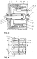
- FIG. 3 shows a schematic representation of a cross section through an exemplary embodiment of the generator-electric motor combination.
- the designated 1 housing leads an input shaft 2 which is connected to a drive machine, not shown.
- This input shaft 2 is supported via a bearing 5 in the housing 1 and carries a designated 6 generator rotor.
- This generator rotor is hollow-cylindrical and has at the outer end of its longitudinal extension inwardly facing permanent magnets 9, which are fixed along the circumference of the generator rotor and have an alternating polarity.
- the output shaft 3 exits from the housing 1.
- This output shaft 3 is supported via a bearing 4 in the housing 1 and is connected to a substantially hollow cylindrical electric motor rotor 7.
- This rotor 7 is deposited via bearings 16, 17 on the input shaft 2 guided deep into the housing.
- the generator rotor 6 and the motor rotor 7 carries at the end of its hollow cylindrical longitudinal extent inwardly facing permanent magnets 8 with alternating polarity.
- the generator rotor 6 spans the electric motor rotor 7 such that the permanent magnets 9 of the generator rotor 6 in the direction of the output shaft 3 behind the permanent magnets 8 of the motor rotor 7 are arranged.
- a stator 12 which is also formed as a hollow cylinder and the input and output shafts 2, 3 comprises.
- a sliding sleeve 13 is arranged, which carries the stator 10 of the electric machine.
- At least one switchable winding 11 is applied, which is in operative connection with the permanent magnets 8, 9 of the rotors 6, 7 of the generator and the electric motor part.
- the stator 10 is displaceable together with the sliding sleeve 13 via a rod 15 coaxial with the input and output shafts 2, 3, wherein the rod 15 passes through an opening 25 in the housing 1 therethrough.
- the axial displaceability of the winding 11 of the stator 10 causes the effective conductor to be varied in the generator and motor parts.
- this variation of the conductor length in the magnetic fields of motor and generator part touches the controllability of the speed and torque ratio of the DC machine according to the invention.
- FIG. 4 the arrangement of the permanent magnets 8, 9 on the generator and electric motor rotors 6, 7 is shown schematically.
- the arrows mark the direction of rotation of the rotors and the winding 11, which is shown only partially, is in a stator position represented, as it corresponds to that according to FIG.
- a switch device 18 in the winding 11 illustrates that this - as described in more detail below - is short-circuited.
- the generator set of magnets is driven by the internal combustion engine with the rotor 6 in the case of short-circuited winding (switch device 18 closed), the movement of the permanent magnets 9 induces a voltage in the winding 11 which results in a current flow in this conductor loop.
- This current causes, if there are permanent magnets of opposite polarity on the rotors 6, 7, a force on the motor rotor 7, which has the same direction as the rotational movement of the drive (generator rotor 6). If there are two poles in the same direction, where does the force act in the opposite direction.
- An essential feature of the invention presented here is therefore to allow the flow of current for the "correct" position of the magnet (switch means 18 closed in Figure 2) and to prevent the "false” position of the permanent magnets (switch means 18 open).
- stator winding must be switched on and off in dependence on the position of the individual poles of the permanent magnets 8, 9, to which the hereinafter described embodiments of the switch device 18 serve.
- the illustrated in Figure 1 first embodiment of the switching device 18 has a first switching element 18a, which consists essentially of a transistor T 1 and a parallel diode D 1 and a transistor T 2 and a diode D 2 connected in parallel, the are switched such that at a defined pole position of the electric motor, the current through a diode D 1 and D 2 and the transistor T 2 and T 1 flows.
- a first switching element 18a which consists essentially of a transistor T 1 and a parallel diode D 1 and a transistor T 2 and a diode D 2 connected in parallel, the are switched such that at a defined pole position of the electric motor, the current through a diode D 1 and D 2 and the transistor T 2 and T 1 flows.
- the at least one winding 11 of the stator 10 is divided by a tap 31 into two partial windings 11a, 11b with an inductance of L 1 or L 2 .
- the preferred case of center tapping is assumed. This does not limit the generality of the following explanations, that it will be readily apparent to those skilled in the art to generalize the described case of center tapping to the more general case of two winding parts 11a and 11b having two dissimilar part inductors.
- a capacitor 32 which is a frequency-dependent resistor and an energy storage, connected.
- the high frequency of the cut-off current caused by the above reasons now causes the capacitor 32 to become low-resistance, so that the winding part 11b is practically disconnected from the winding part 11a.
- the energy contained in the winding part 11b is transformed to the winding part 11a, and the better the coupling of these winding parts 11a, 11b, the better this transformation.
- the current continues to flow after the transformation in the winding part 11a in the same direction, whereby the energy flows from the winding part 11a in the capacitor 32, so that increases the voltage applied thereto.
- the described tapping and the resulting division of the winding 11 into the winding parts 11a, 11b advantageously causes, as a result of the reduced inductance of the winding parts 11a, 11b, the voltage peak at the transistor T 2 to be switched off only a fraction (in the case shown here only 1 / 4) is the otherwise expected voltage spike, so that in an advantageous manner, the risk of damage or destruction of the power semiconductors T 1 , T 2 , D 1 , D 2 is reduced by high voltage spikes.
- the capacitor 32 discharges via the transistor T 1 and the diode D 2 , so that the current in the short-circuit winding 11 runs essentially the same in the right direction.
- FIG. 2 shows a second embodiment of a switching device 18 is shown, which is essentially constructed as the first embodiment shown in Figure 1, so that the same or corresponding parts can be provided with the same reference numerals and need not be described in detail.
- the capacitor 32 in certain states off and on is preceded by a generally designated 40 vibration damping arrangement consisting essentially of a further transistor T 3 , a diode D 3 connected in parallel and a Zener diode connected to the ZD ZD, which for switching the transistor T 3 is used.
- the Zener diode ZD is selected so that the transistor T 3 becomes conductive only when voltage spikes occur, but otherwise it is switched off.
Landscapes
- Engineering & Computer Science (AREA)
- Power Engineering (AREA)
- Control Of Eletrric Generators (AREA)
- Permanent Magnet Type Synchronous Machine (AREA)
- Synchronous Machinery (AREA)
Description
- Die Erfindung betrifft eine Einrichtung zum Schalten von Strömen in einer Statorwicklung einer Generator-Elektromotor-Kombination, wobei die Statorwicklung mindestens eine Wicklung aufweist, die durch die Einrichtung kurzschließbar oder hochohmig schaltbar ist.
- Eine derartige Generator-Elektromotor-Kombination ist aus der deutschen Patentschrift DE 44 08 719 der Anmelderin bekannt. Hierbei ist vorgesehen, daß die Generator-Elektromotor-Kombination ein Gehäuse aufweist, in dem ein Rotor und ein Stator sowohl des Generators als auch des Elektromotors angeordnet sind, die einen an einer Eingangswelle befestigten hohlzylindrischen Generator-Rotor und einen an einer Ausgangswelle befestigten hohlzylindrischen Motor-Rotor aufweist, wobei die Rotoren axial nebeneinander liegen und an ihrer Innenseite in Umfangsrichtung verteilt Permanent-Magnete wechselnder Polarität aufweisen, und die einen innerhalb der hohlzylindrischen Rotoren angeordneten hohlzylindrischen Stator mit wenigstens einer Wicklung, die abhängig von der Stellung der Permanent-Magnete der beiden Rotoren zueinander geschaltet werden, besitzt. Hierbei wird die Statorwicklung je nach gewünschter Kraftrichtung des Elektromotors durch wechselseitiges Schalten von als Schaltelemente fungierenden Leistungshalbleitern einer Halbbrücke der bekannten Einrichtung je nach der Pollage des Elektromotors kurzgeschlossen oder hochohmig geschaltet.
- Nachteilig an der bekannten Einrichtung ist, daß beim Abschalten des Stromes in der Statorwicklung die in der Induktivität gespeicherte Energie zwangsläufig verlorengeht. Außerdem ist nachteilig, daß durch die beim Abschalten entstehenden extrem hohen Spannungsspitzen die Schaltelemente gefährdet werden.
- Es ist daher Aufgabe der vorliegenden Erfindung, eine Einrichtung der eingangs genannten Art derart weiterzubilden, daß zumindest eine Reduzierung der beim Abschalten entstehenden Spannungsspitzen erzielt wird.
- Diese Aufgabe wird erfindungsgemäß durch die kennzeichnenden Merkmale des Anspruchs 1 gelöst.
- Vorteilhafte Weiterbildungen der Erfindung sind Gegenstand der Unteransprüche.
- Weitere Einzelheiten und Vorteile der Erfindung sind dem Ausführungsbeispiel zu entnehmen, daß im folgenden anhand der Figuren beschrieben wird. Es zeigen:
- Figur 1
- ein Blockschaltbild eines ersten Ausführungsbeispiels der Einrichtung,
- Figur 2
- ein Blockschaltbild eines zweiten Ausführungsbeispiels der Einrichtung,
- Figur 3
- eine schematische Querschnittszeichnung durch eine Generator-Elektromotor-Kombination,
- Figur 4
- eine schematische Darstellung der Überdeckung der Statorwicklung über den Permanent-Magneten der Rotoren des Generators und des Elektromotors gemäß Figur 3.
- Bevor nun die beiden in den Figuren 1 und 2 dargestellten Ausführungsbeispiele einer Einrichtung zum Schalten von Strömen in einer Statorwicklung einer Generator-Elektromotor-Kombination näher erläutert werden, soll der besseren Verständlichkeit halber zunächst kurz die in den Figuren 3 und 4 dargestellte Generator-Elektromotor-Kombination erläutert werden, welche bereits aus der DE 44 08 719 C1 bekannt ist, so daß zur Vermeidung von Wiederholungen bezüglich weiter unten nicht aufgeführter Merkmale dieser Generator-Elektromotor-Kombination auf diese Druckschrift explizit bezuggenommen und deren technische Lehre durch diese Bezugnahme zum Gegenstand der vorliegenden Anmeldung gemacht wird.
- In Figur 3 ist in schematischer Darstellung ein Querschnitt durch ein Ausführungsbeispiel der Generator-Elektromotor-Kombination dargestellt. In das mit 1 bezeichnete Gehäuse führt eine Eingangswelle 2, die mit einer nicht dargestellten Antriebsmaschine verbunden ist. Diese Eingangswelle 2 ist über ein Lager 5 in dem Gehäuse 1 abgestützt und trägt einen mit 6 bezeichneten Generator-Rotor. Dieser Generator-Rotor ist hohlzylindrisch ausgebildet und weist an dem äußeren Ende seiner Längsstreckung nach innen weisende Permanent-Magneten 9 auf, die entlang des Umfangs des Generator-Rotors befestigt sind und eine wechselnde Polarität aufweisen.
- Auf der dem Lager 5 gegenüberliegenden Seite des Gehäuses 1 tritt die Ausgangswelle 3 aus dem Gehäuse 1 aus. Diese Ausgangswelle 3 stützt sich über ein Lager 4 in dem Gehäuse 1 ab und ist mit einem im wesentlichen hohlzylindrisch ausgebildeten Elektromotor-Rotor 7 verbunden. Dieser Rotor 7 ist über Lager 16, 17 auf der tief in das Gehäuse geführten Eingangswelle 2 abgelagert. Ebenso wie der Generator-Rotor 6 trägt auch der Motor-Rotor 7 am Ende seiner hohlzylindrischen Längserstreckung nach innen weisende Permanent-Magnete 8 mit wechselnder Polarität.
- Von besonderer Bedeutung für den kurzen Aufbau der Generator-Elektromotor-Kombination ist, daß der Generator-Rotor 6 den Elektromotor-Rotor 7 derart umspannt, daß die Permanent-Magneten 9 des Generator-Rotors 6 in Richtung zur Ausgangswelle 3 hinter den Permanent-Magneten 8 des Motor-Rotors 7 angeordnet sind.
- Von der Innenseite des Gehäuses 1 erstreckt sich in den hohlzylindrischen Raum des Generator- und Motor-Rotors ein Statorträger 12, der ebenfalls hohlzylindrisch ausgebildet ist und die Eingangs- und Ausgangswelle 2, 3 umfaßt. Auf diesem Statorträger 12 ist eine Schiebehülse 13 angeordnet, die den Stator 10 der Elektromaschine trägt.
- Auf dem Stator 10 ist wenigstens eine schaltbare Wicklung 11 aufgebracht, die in Wirkzusammenhang mit den Permanent-Magneten 8, 9 der Rotoren 6, 7 von dem Generator- und dem Elektromotorteil steht.
- Der Stator 10 ist zusammen mit der Schiebehülse 13 über eine Stange 15 koaxial zur Eingangs- und Ausgangswelle 2, 3 verschiebbar, wobei die Stange 15 durch eine Öffnung 25 in dem Gehäuse 1 hindurchdurchragt.
- Die axiale Verschieblichkeit der Wicklung 11 des Stators 10 bewirkt, daß die wirksame Leiterlänger im Generator- und Motorteil variiert werden kann. Auf diese Variation der Leiterlänger in den Magnetfeldern von Motor- und Generatorteil berührt die Steuer- bzw. Regelbarkeit der Drehzahl- und Momentenübersetzung der erfindungsgemäßen Gleichstrom-Maschine.
- In Figur 4 ist die Anordnung der Permanent-Magneten 8, 9 auf den Generator- und Elektromotor-Rotoren 6, 7 schematisch dargestellt. Die Pfeile markieren die Drehrichtung der Rotoren und die nur teilweise dargestellte Wicklung 11 ist in einer Statorposition dargestellt, wie sie der gemäß Figur 1 entspricht. Eine Schalter-Einrichtung 18 in der Wicklung 11 verdeutlicht, daß diese - wie nachstehend noch detailliert beschrieben - kurzschließbar ist.
- Wird der generatorische Magnetensatz mit dem Rotor 6 bei kurzgeschlossener Wicklung (Schalter-Einrichtung 18 geschlossen) vom Verbrennungsmotor angetrieben, so wird durch die Bewegung der Permanent-Magnete 9 eine Spannung in der Wicklung 11 induziert, die in dieser Leiterschleife einen Stromfluß zur Folge hat. Dieser Strom bewirkt, sofern sich auf den Rotoren 6, 7 Permanent-Magnete entgegengesetzter Polarität befinden, eine Kraft auf den Motor-Rotor 7, die die selbe Richtung hat, wie die Drehbewegung des Antriebs (Generator-Rotor 6). Stehen sich jeweils zwei gleichsinnige Pole gegenüber, wo wirkt die Kraft in die entgegengesetzte Richtung.
- Ist die Wicklung 11 permanent kurzgeschlossen, so wirkt bei Drehung der Generator-Seite eine Kraft mit ständig wechselndem Vorzeichen auf den Antrieb. Es kommt daher auch bei abtriebsseitigen Leerlauf keine Drehbewegung zustande. Je nachdem welche Kraftrichtung am Abtrieb, das heißt am Motor-Rotor 7 erwünscht ist, gibt es also immer eine "richtige" und eine "falsche" Stellung der beiden Permanent-Magnet-Sätze zueinander.
- Ein wesentliches Merkmal der hier vorgestellten Erfindung ist es daher, den Stromfluß für die "richtige" Stellung der Magneten zu ermöglichen (Schalter-Einrichtung 18 in Figur 2 geschlossen) und für die "falsche" Stellung der Permanent-Magnete zu unterbinden (Schalter-Einrichtung 18 offen).
- Wie bereits dargelegt und wie in den Figuren 1 und 2 durch das Schaltersymbol für die Schalter-Einrichtung 18 angedeutet wurde, muß die Statorwicklung in Abhängigkeit von der Lage der einzelnen Pole der Permanent-Magnete 8, 9 zueinander ein- und ausgeschaltet werden, wozu die nachstehend beschriebenen Ausführungsbeispiele der Schalter-Einrichtung 18 dienen.
- Das in Figur 1 dargestellte erste Ausführungsbeispiel der Schalter-Einrichtung 18 weist ein erstes Schaltelement 18a, das im wesentlichen aus einen Transistor T1 und eine parallel dazu geschaltete Diode D1 sowie einen Transistor T2 und eine parallel dazu geschaltete Diode D2 auf, die derart geschaltet sind, daß bei einer definierten Pollage des Elektromotors der Strom durch eine Diode D1 bzw. D2 und den Transistor T2 bzw. T1 fließt.
- In Figur 1 wird beipielhaft davon ausgegangen, daß der Transistor T1 leitend ist, wenn die Permanent-Magneten 8 mit ihrem Nordpol den Motor-Rotor 7 beaufschlagen, und daß der Transistor T2 leitend ist, wenn die Südpole der Permanent-Magneten 8 den Motor-Rotor 7 beaufschlagen. In diesem Fall fließt der Strom, bedingt durch die Pollage des Motor-Rotors 7, durch die Diode D1 und den Transistor T2, während bei einer Änderung der Pollage der Strom durch die Diode D2 und den Transistor T1 fließt, was voraussetzt, daß bei einer Änderung der Pollage der Transistor T2 abgeschaltet werden muß. Dies bedingt aufgrund der Induktivität L der Wicklung 11 die bereits eingangs erwähnten extrem hohen Spannungsspitzen, die proportional zur Induktivität L der Kurzschlußwicklung 11 und der zeitlichen Ableitung der Stromänderung am Kollektor des Transistors T2 (T1) sind, so daß also die Spannungsspitzen umso höher sind, je kürzer die Abschaltzeit des Transistors T2 (T1) ist, d. h., je höher die Drehzahl der Generator-Elektromotor-Kombination ist.
- Erfindungsgemäß ist nun vorgesehen, daß die wenigstens eine Wicklung 11 des Stators 10 durch eine Anzapfung 31 in zwei Teilwicklungen 11a, 11b mit einer Induktivität von L1 bzw. L2 aufgeteilt wird. Vorzugsweise ist hierbei vorgesehen, daß die Anzapfung 31 eine Mittenanzapfung ist, durch die die Kurzschlußwicklung 11 in zwei gleiche Wicklungsteile 11a und 11b mit jeweils einer Induktivität von L1 = L2 = L/4 aufgeteilt ist. Im folgenden wird der einfacheren Beschreibung halber von dem bevorzugten Fall der Mittenanzapfung ausgegangen. Diese schränkt die Allgemeingültigkeit der nachfolgenden Erläuterungen nicht ein, daß es dem Fachmann ohne weiteres geläufig ist, den beschriebenen Fall der Mittenanzapfung auf den allgemeineren Fall von zwei Wicklungsteilen 11a und 11b mit zwei ungleichen Teil-Induktivitäten zu verallgemeinern.
- In der Anzapfung 31 ist ein Kondensator 32, der einen frequenzabhängigen Widerstand und einen Energiespeicher darstellt, geschaltet. Die aus vorstehend genannten Gründen hohe Frequenz des Abschaltstroms bewirkt nun, daß der Kondensator 32 niederohmig wird, so daß der Wicklungsteil 11b praktisch vom Wicklungsteil 11a getrennt ist. Die im Wicklungsteil 11b befindliche Energie wird auf den Wicklungsteil 11a transformiert, wobei diese Transformation umso besser ist, je besser die Kopplung dieser Wicklungsteile 11a, 11b ist. Der Strom fließt nach der Transformation im Wicklungsteil 11a in unveränderter Richtung weiter, wodurch die Energie aus dem Wicklungsteil 11a in den Kondensator 32 abfließt, so daß sich an diesem die anliegende Spannung erhöht.
- Durch die beschriebene Anzapfung und die dadurch bewirkte Teilung der Wicklung 11 in die Wicklungsteile 11a, 11b wird vorteilhafterweise bewirkt, daß infolge der reduzierten Induktivität der Wicklungsteile 11a, 11b die Spannungsspitze am abschaltenden Transistor T2 nur einen Bruchteil (in dem hier gezeigten Fall nur 1/4) der ansonsten zu erwartenden Spannungsspitze ist, so daß in vorteilhafter Art und Weise die Gefahr einer Beschädigung oder Zerstörung der Leistungshalbleiter T1 , T2 , D1, D2 durch hohe Spannungsspitzen reduziert wird.
- Wird nun im darauffolgenden Zyklus der Transistor T1 angesteuert, so entlädt sich der Kondensator 32 über den Transistor T1 und die Diode D2, so daß der Strom in der Kurzschlußwicklung 11 im wesentlichen gleich in die richtige Richtung läuft.
- In Figur 2 ist ein zweites Ausführungsbeispiel einer Schalt-Einrichtung 18 dargestellt, welches im wesentlichen wie das in Figur 1 dargestellte erste Ausführungsbeispiel aufgebaut ist, so daß gleiche oder einander entsprechende Teile mit gleichen Bezugszeichen versehen werden können und nicht mehr näher beschrieben werden müssen.
- Der wesentliche Unterschied zwischen den beiden Ausführungsbeispielen besteht darin, daß zur Unterdrückung eventueller Schwingungen, die durch einen LC-Schwingkreis, wie er durch die Kurzschlußwicklung 11 und den Kondensator 32 ausgebildet wird, vorgesehen ist, den Kondensator 32 in bestimmten Zuständen ab- und zuzuschalten. Hierzu ist vorgesehen, daß dem Kondensator 32 in der Anzapfung 31 eine allgemein mit 40 bezeichnete Schwingungsdämpfungsanordnung vorgeschalten ist, die im wesentlichen aus einem weiteren Transistor T3, einer parallel dazu geschalteten Diode D3 und einer mit der Anzapfung 31 verbundenen Zenerdiode ZD besteht, welche zum Schalten des Transistors T3 dient. Die Zenerdiode ZD ist so ausgewählt, daß der Transistor T3 nur beim Auftreten von Spannungsspitzen leitend wird, sonst aber abgeschaltet ist.
-
- 1
- Gehäuse
- 2
- Eingangswelle
- 3
- Ausgangswelle
- 4
- Lager
- 5
- Lager
- 6
- Generator-Rotor
- 7
- Elektromotor-Rotor
- 8
- Permanent-Magnet
- 9
- Permanent-Magnet
- 10
- Stator
- 11
- Wicklung
11a Wicklungsteil
11b Wicklungsteil - 12
- Statorträger
- 13
- Schiebehülse
- 15
- Stange
- 16
- Lager
- 17
- Lager
- 18
- Schalter-Einrichtung
18a Schaltelement - 25
- Öffnung
- 31
- Anzapfung
- 32
- Kondensator
- D1
- Diode
- D2
- Diode
- D3
- Diode
- T1
- Transistor
- T2
- Transistor
- T3
- Transistor
Claims (7)
- Einrichtung zum Schalten von Strömen in einer Statorwicklung einer Generator-Elektromotor-Kombination, wobei die Statorwicklung mindestens eine Wicklung (11) aufweist, die durch die Einrichtung (18) kurzschließbar oder hochohmig schaltbar ist, dadurch gekennzeichnet, daß die Wicklung (11) mit einer Induktivität L durch mindestens eine Anzapfung (31) in zwei Wicklungsteile (11a, 11b) mit einer Induktivität von L1 bzw. L2 aufgeteilt ist, und daß in die Anzapfung (31) ein Kondensator (32) geschaltet ist, der bei einer Beaufschlagung durch einen hochfrequenten Abschaltstrom die beiden Wicklungsteile (11a, 11b) der Wicklung (11) zumindest teilweise elektrisch trennt.
- Einrichtung nach Anspruch 1, dadurch gekennzeichnet, daß die Anzapfung (31) eine Mittenanzapfung ist, durch die die Wicklung (11) in zwei Wicklungsteile (11a,11b) mit einer im wesentlichen gleichen Induktivität L1 = L2 = L/4 aufgeteilt ist.
- Einrichtung nach einem der vorangehenden Ansprüche, dadurch gekennzeichnet, daß die Einrichtung (18) ersten Schaltkondensator (T1) und eine parallel dazugeschaltete erste Diode (D1) und einen zweiten Schaltkondensator (T2) und eine parallel dazugeschaltete zweite Diode (D2) aufweist, wobei bei einer definierten Pollage von Permanent-Magneten (8, 9) der Generator-Elektromotor-Kombination ein Strom (I) durch die erste Diode (D1) und den zweiten Schalttransistor (T2) und bei einer der ersten Pollagen entgegengesetzten zweiten Pollage der Permanent-Magneten (8, 9) durch die zweite Diode (D2) und den ersten Schalttransistor (T1) fließt.
- Einrichtung nach einem der vorangehenden Ansprüche, dadurch gekennzeichnet, daß die Einrichtung (18) eine Schwingungsdämpfungsanordnung (40) zur Unterdrückung von durch die Kurzschlußwicklung (11) und den Kondensator (32) hervorgerufenen Schwingungen aufweist.
- Einrichtung nach Anspruch 6, dadurch gekennzeichnet, daß die Schwingungsdämpfungsanordnung (40) einen dritten Schalttransistor (T3) und eine parallel dazugeschaltete dritte Diode (D3) aufweist, und daß die Ansteuerung des dritten Schalttransistors (T3) durch eine mit der Anzapfung (31) verbundene Zenerdiode (ZD) folgt.
- Generator-Elektromotor-Kombination, gekennzeichnet durch eine Einrichtung (18) für das Schalten von Strömen in ihrer Statorwicklung (11) gemäß einem der Ansprüche 1-5.
- Generator-Elektromotor-Kombination nach Anspruch 7, dadurch gekennzeichnet, daß die Generator-Elektromotor-Kombination ein Gehäuse (1) aufweist, in dem ein Rotor und der Stator sowohl des Generators als auch des Elektromotors angeordnet sind, die einen an einen Eingangswelle (2) befestigten hohlzylindrischen Generator-Rotor (6) und einen an einer Ausgangswelle (3) befestigten hohlzylindrischen Motor-Rotor (7) aufweist, wobei die Rotoren (6, 7) axial nebeneinander liegen und an ihrer Innenseite in Umfangsrichtung verteilt Permanent-Magnete (8, 9) wechselnder Polarität aufweisen, und daß die Generator-Elektromotor-Kombination einen innerhalb der hohlzylindrischen Rotoren (6, 7) angeordneten hohlzylindrischen Stator mit wenigstens einer Wicklung (11), die abhängig von der Stellung der Permanent-Magneten (8, 9) der beiden Rotoren (6, 7) zueinander geschaltet werden, besitzt, wobei die Wicklung (11) je nach gewünschter Kraftrichtung des Elektromotors durch wechselseitiges Schalten durch die Einrichtung (18) je nach Pollage des Elektromotors kurzschließbar oder hochohmig schaltbar ist.
Applications Claiming Priority (2)
| Application Number | Priority Date | Filing Date | Title |
|---|---|---|---|
| DE19853516 | 1998-11-20 | ||
| DE19853516A DE19853516A1 (de) | 1998-11-20 | 1998-11-20 | Einrichtung zum Schalten von Strömen in einer Statorwicklung einer Generator-Elektromotor-Kombination |
Publications (3)
| Publication Number | Publication Date |
|---|---|
| EP1003271A2 EP1003271A2 (de) | 2000-05-24 |
| EP1003271A3 EP1003271A3 (de) | 2001-12-19 |
| EP1003271B1 true EP1003271B1 (de) | 2007-01-10 |
Family
ID=7888414
Family Applications (1)
| Application Number | Title | Priority Date | Filing Date |
|---|---|---|---|
| EP99120038A Expired - Lifetime EP1003271B1 (de) | 1998-11-20 | 1999-10-18 | Einrichtung zum Schalten von Strömen in einer Statorwicklung einer Generator-Elektromotor-Kombination |
Country Status (2)
| Country | Link |
|---|---|
| EP (1) | EP1003271B1 (de) |
| DE (2) | DE19853516A1 (de) |
Families Citing this family (3)
| Publication number | Priority date | Publication date | Assignee | Title |
|---|---|---|---|---|
| DE10237451A1 (de) * | 2002-08-16 | 2004-05-19 | Siemens Ag | Einrichtung und Verfahren zum Schalten von Strömen in einer Statorwicklung einer Generator-Elektromotor-Kombination |
| DE10354604B4 (de) | 2003-11-21 | 2016-10-13 | Gesellschaft für Aufladetechnik und Spindelbau mbH | Stufenlos schaltbares, magnetodynamisches Getriebe |
| DE102004041227A1 (de) * | 2004-08-26 | 2006-03-02 | Volkswagen Ag | Generator-Elektromotor-Kombination |
Family Cites Families (6)
| Publication number | Priority date | Publication date | Assignee | Title |
|---|---|---|---|---|
| DE329303C (de) * | 1920-11-25 | Siemens Schuckertwerke G M B H | Verfahren zum Ausschalten von Wicklungen mit hoher Selbstinduktion | |
| DE1035255B (de) * | 1956-04-30 | 1958-07-31 | Elmeg | Anordnung zur Schnellentkupplung elektromagnetischer Kupplungen |
| DE3435069A1 (de) * | 1984-09-25 | 1986-04-03 | Horst Dipl.-Ing. Kopetzky (FH), 8025 Unterhaching | Schaltungsanordnung zur verhinderung von abschaltspannungsspitzen |
| DD238141A1 (de) * | 1985-06-05 | 1986-08-06 | Stern Radio Berlin Bt Quedlinb | Schaltungsanordnung zum schnellen und verlustarmen umschalten von induktivitaeten |
| DE4408719C1 (de) * | 1994-03-15 | 1995-07-06 | Volkswagen Ag | Generator-Motor-Kombination |
| GB9603181D0 (en) * | 1996-02-15 | 1996-04-17 | Motorola Ltd | Switching circuit for an inductive load |
-
1998
- 1998-11-20 DE DE19853516A patent/DE19853516A1/de not_active Withdrawn
-
1999
- 1999-10-18 EP EP99120038A patent/EP1003271B1/de not_active Expired - Lifetime
- 1999-10-18 DE DE59914143T patent/DE59914143D1/de not_active Expired - Lifetime
Also Published As
| Publication number | Publication date |
|---|---|
| EP1003271A3 (de) | 2001-12-19 |
| EP1003271A2 (de) | 2000-05-24 |
| DE59914143D1 (de) | 2007-02-22 |
| DE19853516A1 (de) | 2000-05-25 |
Similar Documents
| Publication | Publication Date | Title |
|---|---|---|
| DE3010435C2 (de) | ||
| DE69833081T2 (de) | Motor mit innerem Permanentmagnetrotor | |
| DE68914841T2 (de) | Elektrischer motor. | |
| DE3632509C2 (de) | ||
| DE2419432A1 (de) | Kollektorloser gleichstrommotor | |
| EP1380094B1 (de) | Elektromotor, insbesondere elektronisch kommutierter gleichstrommotor | |
| DE3342986C2 (de) | ||
| DE102007025971A1 (de) | Elektrische Maschine mit hybriderregtem Rotor | |
| DE19743314A1 (de) | Bürstenloser Motor mit Permanentmagneten | |
| DE2445765A1 (de) | Elektrischer generator | |
| DE69933250T2 (de) | Elektrische Maschine mit doppelter Erregung, und insbesondere Fahrzeuggenerator | |
| WO2006089605A1 (de) | Verfahren zum betrieb eines zweisträngigen elektronisch kommutierten motors, und motor zur durchführung eines solchen verfahrens | |
| CH667168A5 (de) | Mehrphasige elektrische maschine mit gesteuerter magnetflussdichte. | |
| DE1763722A1 (de) | Elektrischer Generator | |
| EP0986855B1 (de) | Elektronisch kommutierter motor | |
| DE3913501A1 (de) | Kommutatorloser, magnetisch gesteuerter elektromotor | |
| EP0583328B1 (de) | Elektronische steuerschaltung für die speisung von ohmisch-induktiven lasten durch gleichstromimpulse | |
| EP0422539A1 (de) | Elektrische Maschine mit einem Rotor und einem Stator | |
| DE2231590A1 (de) | Permanentmagnet-generator | |
| EP0614263A1 (de) | Einphasiger Reluktanzmotor zum Starten dieses Motors in einer gewünschten Drehrichtung | |
| DE19715943A1 (de) | Verfahren zum Schutzbetrieb für einen geschalteten elektrischen Reluktanzmotor | |
| EP1003271B1 (de) | Einrichtung zum Schalten von Strömen in einer Statorwicklung einer Generator-Elektromotor-Kombination | |
| DE4036565C1 (en) | Electronic drive system using variable reluctance electric motor - slows down variations in magnetic induction of stator by electronic control of winding current | |
| EP0501521B1 (de) | Bürstenloser Gleichstrommotor für niedrige Drehzahlen | |
| DE3012506C2 (de) | Kommutatormotor mit zwei Kommutatoren |
Legal Events
| Date | Code | Title | Description |
|---|---|---|---|
| PUAI | Public reference made under article 153(3) epc to a published international application that has entered the european phase |
Free format text: ORIGINAL CODE: 0009012 |
|
| AK | Designated contracting states |
Kind code of ref document: A2 Designated state(s): AT BE CH CY DE DK ES FI FR GB GR IE IT LI LU MC NL PT SE |
|
| AX | Request for extension of the european patent |
Free format text: AL;LT;LV;MK;RO;SI |
|
| PUAL | Search report despatched |
Free format text: ORIGINAL CODE: 0009013 |
|
| AK | Designated contracting states |
Kind code of ref document: A3 Designated state(s): AT BE CH CY DE DK ES FI FR GB GR IE IT LI LU MC NL PT SE |
|
| AX | Request for extension of the european patent |
Free format text: AL;LT;LV;MK;RO;SI |
|
| RIC1 | Information provided on ipc code assigned before grant |
Free format text: 7H 02K 51/00 A, 7H 02P 17/00 B, 7H 03K 17/0814 B |
|
| 17P | Request for examination filed |
Effective date: 20020619 |
|
| AKX | Designation fees paid |
Free format text: AT BE CH CY DE DK ES FI FR GB GR IE IT LI LU MC NL PT SE |
|
| GRAP | Despatch of communication of intention to grant a patent |
Free format text: ORIGINAL CODE: EPIDOSNIGR1 |
|
| GRAS | Grant fee paid |
Free format text: ORIGINAL CODE: EPIDOSNIGR3 |
|
| GRAA | (expected) grant |
Free format text: ORIGINAL CODE: 0009210 |
|
| AK | Designated contracting states |
Kind code of ref document: B1 Designated state(s): AT BE CH CY DE DK ES FI FR GB GR IE IT LI LU MC NL PT SE |
|
| PG25 | Lapsed in a contracting state [announced via postgrant information from national office to epo] |
Ref country code: NL Free format text: LAPSE BECAUSE OF FAILURE TO SUBMIT A TRANSLATION OF THE DESCRIPTION OR TO PAY THE FEE WITHIN THE PRESCRIBED TIME-LIMIT Effective date: 20070110 Ref country code: IE Free format text: LAPSE BECAUSE OF FAILURE TO SUBMIT A TRANSLATION OF THE DESCRIPTION OR TO PAY THE FEE WITHIN THE PRESCRIBED TIME-LIMIT Effective date: 20070110 Ref country code: FI Free format text: LAPSE BECAUSE OF FAILURE TO SUBMIT A TRANSLATION OF THE DESCRIPTION OR TO PAY THE FEE WITHIN THE PRESCRIBED TIME-LIMIT Effective date: 20070110 Ref country code: DK Free format text: LAPSE BECAUSE OF FAILURE TO SUBMIT A TRANSLATION OF THE DESCRIPTION OR TO PAY THE FEE WITHIN THE PRESCRIBED TIME-LIMIT Effective date: 20070110 |
|
| REG | Reference to a national code |
Ref country code: GB Ref legal event code: FG4D Free format text: NOT ENGLISH |
|
| REG | Reference to a national code |
Ref country code: IE Ref legal event code: FG4D Free format text: LANGUAGE OF EP DOCUMENT: GERMAN |
|
| REF | Corresponds to: |
Ref document number: 59914143 Country of ref document: DE Date of ref document: 20070222 Kind code of ref document: P |
|
| PG25 | Lapsed in a contracting state [announced via postgrant information from national office to epo] |
Ref country code: SE Free format text: LAPSE BECAUSE OF FAILURE TO SUBMIT A TRANSLATION OF THE DESCRIPTION OR TO PAY THE FEE WITHIN THE PRESCRIBED TIME-LIMIT Effective date: 20070410 |
|
| PG25 | Lapsed in a contracting state [announced via postgrant information from national office to epo] |
Ref country code: ES Free format text: LAPSE BECAUSE OF FAILURE TO SUBMIT A TRANSLATION OF THE DESCRIPTION OR TO PAY THE FEE WITHIN THE PRESCRIBED TIME-LIMIT Effective date: 20070421 |
|
| GBT | Gb: translation of ep patent filed (gb section 77(6)(a)/1977) |
Effective date: 20070418 |
|
| PG25 | Lapsed in a contracting state [announced via postgrant information from national office to epo] |
Ref country code: PT Free format text: LAPSE BECAUSE OF FAILURE TO SUBMIT A TRANSLATION OF THE DESCRIPTION OR TO PAY THE FEE WITHIN THE PRESCRIBED TIME-LIMIT Effective date: 20070611 |
|
| NLV1 | Nl: lapsed or annulled due to failure to fulfill the requirements of art. 29p and 29m of the patents act | ||
| REG | Reference to a national code |
Ref country code: IE Ref legal event code: FD4D |
|
| EN | Fr: translation not filed | ||
| PLBE | No opposition filed within time limit |
Free format text: ORIGINAL CODE: 0009261 |
|
| STAA | Information on the status of an ep patent application or granted ep patent |
Free format text: STATUS: NO OPPOSITION FILED WITHIN TIME LIMIT |
|
| 26N | No opposition filed |
Effective date: 20071011 |
|
| BERE | Be: lapsed |
Owner name: VOLKSWAGEN A.G. Effective date: 20071031 |
|
| PG25 | Lapsed in a contracting state [announced via postgrant information from national office to epo] |
Ref country code: IT Free format text: LAPSE BECAUSE OF FAILURE TO SUBMIT A TRANSLATION OF THE DESCRIPTION OR TO PAY THE FEE WITHIN THE PRESCRIBED TIME-LIMIT Effective date: 20070110 Ref country code: GR Free format text: LAPSE BECAUSE OF FAILURE TO SUBMIT A TRANSLATION OF THE DESCRIPTION OR TO PAY THE FEE WITHIN THE PRESCRIBED TIME-LIMIT Effective date: 20070411 Ref country code: FR Free format text: LAPSE BECAUSE OF FAILURE TO SUBMIT A TRANSLATION OF THE DESCRIPTION OR TO PAY THE FEE WITHIN THE PRESCRIBED TIME-LIMIT Effective date: 20070831 |
|
| PG25 | Lapsed in a contracting state [announced via postgrant information from national office to epo] |
Ref country code: MC Free format text: LAPSE BECAUSE OF NON-PAYMENT OF DUE FEES Effective date: 20071031 |
|
| REG | Reference to a national code |
Ref country code: CH Ref legal event code: PL |
|
| PG25 | Lapsed in a contracting state [announced via postgrant information from national office to epo] |
Ref country code: LI Free format text: LAPSE BECAUSE OF NON-PAYMENT OF DUE FEES Effective date: 20071031 Ref country code: CH Free format text: LAPSE BECAUSE OF NON-PAYMENT OF DUE FEES Effective date: 20071031 |
|
| PG25 | Lapsed in a contracting state [announced via postgrant information from national office to epo] |
Ref country code: BE Free format text: LAPSE BECAUSE OF NON-PAYMENT OF DUE FEES Effective date: 20071031 |
|
| PG25 | Lapsed in a contracting state [announced via postgrant information from national office to epo] |
Ref country code: FR Free format text: LAPSE BECAUSE OF FAILURE TO SUBMIT A TRANSLATION OF THE DESCRIPTION OR TO PAY THE FEE WITHIN THE PRESCRIBED TIME-LIMIT Effective date: 20070110 |
|
| PG25 | Lapsed in a contracting state [announced via postgrant information from national office to epo] |
Ref country code: AT Free format text: LAPSE BECAUSE OF NON-PAYMENT OF DUE FEES Effective date: 20071018 |
|
| PG25 | Lapsed in a contracting state [announced via postgrant information from national office to epo] |
Ref country code: CY Free format text: LAPSE BECAUSE OF FAILURE TO SUBMIT A TRANSLATION OF THE DESCRIPTION OR TO PAY THE FEE WITHIN THE PRESCRIBED TIME-LIMIT Effective date: 20070110 |
|
| PG25 | Lapsed in a contracting state [announced via postgrant information from national office to epo] |
Ref country code: LU Free format text: LAPSE BECAUSE OF NON-PAYMENT OF DUE FEES Effective date: 20071018 |
|
| PGFP | Annual fee paid to national office [announced via postgrant information from national office to epo] |
Ref country code: DE Payment date: 20131031 Year of fee payment: 15 Ref country code: GB Payment date: 20131031 Year of fee payment: 15 |
|
| REG | Reference to a national code |
Ref country code: DE Ref legal event code: R119 Ref document number: 59914143 Country of ref document: DE |
|
| GBPC | Gb: european patent ceased through non-payment of renewal fee |
Effective date: 20141018 |
|
| PG25 | Lapsed in a contracting state [announced via postgrant information from national office to epo] |
Ref country code: DE Free format text: LAPSE BECAUSE OF NON-PAYMENT OF DUE FEES Effective date: 20150501 Ref country code: GB Free format text: LAPSE BECAUSE OF NON-PAYMENT OF DUE FEES Effective date: 20141018 |