EP1001224A2 - Chambre de combustion pour une turbine à gaz - Google Patents
Chambre de combustion pour une turbine à gaz Download PDFInfo
- Publication number
- EP1001224A2 EP1001224A2 EP99121873A EP99121873A EP1001224A2 EP 1001224 A2 EP1001224 A2 EP 1001224A2 EP 99121873 A EP99121873 A EP 99121873A EP 99121873 A EP99121873 A EP 99121873A EP 1001224 A2 EP1001224 A2 EP 1001224A2
- Authority
- EP
- European Patent Office
- Prior art keywords
- pilot
- air
- main
- combustor
- tube
- Prior art date
- Legal status (The legal status is an assumption and is not a legal conclusion. Google has not performed a legal analysis and makes no representation as to the accuracy of the status listed.)
- Granted
Links
Images


Classifications
-
- F—MECHANICAL ENGINEERING; LIGHTING; HEATING; WEAPONS; BLASTING
- F23—COMBUSTION APPARATUS; COMBUSTION PROCESSES
- F23L—SUPPLYING AIR OR NON-COMBUSTIBLE LIQUIDS OR GASES TO COMBUSTION APPARATUS IN GENERAL ; VALVES OR DAMPERS SPECIALLY ADAPTED FOR CONTROLLING AIR SUPPLY OR DRAUGHT IN COMBUSTION APPARATUS; INDUCING DRAUGHT IN COMBUSTION APPARATUS; TOPS FOR CHIMNEYS OR VENTILATING SHAFTS; TERMINALS FOR FLUES
- F23L7/00—Supplying non-combustible liquids or gases, other than air, to the fire, e.g. oxygen, steam
-
- F—MECHANICAL ENGINEERING; LIGHTING; HEATING; WEAPONS; BLASTING
- F23—COMBUSTION APPARATUS; COMBUSTION PROCESSES
- F23C—METHODS OR APPARATUS FOR COMBUSTION USING FLUID FUEL OR SOLID FUEL SUSPENDED IN A CARRIER GAS OR AIR
- F23C9/00—Combustion apparatus characterised by arrangements for returning combustion products or flue gases to the combustion chamber
-
- F—MECHANICAL ENGINEERING; LIGHTING; HEATING; WEAPONS; BLASTING
- F23—COMBUSTION APPARATUS; COMBUSTION PROCESSES
- F23R—GENERATING COMBUSTION PRODUCTS OF HIGH PRESSURE OR HIGH VELOCITY, e.g. GAS-TURBINE COMBUSTION CHAMBERS
- F23R3/00—Continuous combustion chambers using liquid or gaseous fuel
- F23R3/005—Combined with pressure or heat exchangers
-
- F—MECHANICAL ENGINEERING; LIGHTING; HEATING; WEAPONS; BLASTING
- F23—COMBUSTION APPARATUS; COMBUSTION PROCESSES
- F23R—GENERATING COMBUSTION PRODUCTS OF HIGH PRESSURE OR HIGH VELOCITY, e.g. GAS-TURBINE COMBUSTION CHAMBERS
- F23R3/00—Continuous combustion chambers using liquid or gaseous fuel
- F23R3/02—Continuous combustion chambers using liquid or gaseous fuel characterised by the air-flow or gas-flow configuration
- F23R3/04—Air inlet arrangements
- F23R3/10—Air inlet arrangements for primary air
- F23R3/12—Air inlet arrangements for primary air inducing a vortex
- F23R3/14—Air inlet arrangements for primary air inducing a vortex by using swirl vanes
-
- F—MECHANICAL ENGINEERING; LIGHTING; HEATING; WEAPONS; BLASTING
- F23—COMBUSTION APPARATUS; COMBUSTION PROCESSES
- F23R—GENERATING COMBUSTION PRODUCTS OF HIGH PRESSURE OR HIGH VELOCITY, e.g. GAS-TURBINE COMBUSTION CHAMBERS
- F23R3/00—Continuous combustion chambers using liquid or gaseous fuel
- F23R3/28—Continuous combustion chambers using liquid or gaseous fuel characterised by the fuel supply
- F23R3/34—Feeding into different combustion zones
- F23R3/343—Pilot flames, i.e. fuel nozzles or injectors using only a very small proportion of the total fuel to insure continuous combustion
-
- F—MECHANICAL ENGINEERING; LIGHTING; HEATING; WEAPONS; BLASTING
- F23—COMBUSTION APPARATUS; COMBUSTION PROCESSES
- F23R—GENERATING COMBUSTION PRODUCTS OF HIGH PRESSURE OR HIGH VELOCITY, e.g. GAS-TURBINE COMBUSTION CHAMBERS
- F23R3/00—Continuous combustion chambers using liquid or gaseous fuel
- F23R3/42—Continuous combustion chambers using liquid or gaseous fuel characterised by the arrangement or form of the flame tubes or combustion chambers
- F23R3/60—Support structures; Attaching or mounting means
-
- F—MECHANICAL ENGINEERING; LIGHTING; HEATING; WEAPONS; BLASTING
- F23—COMBUSTION APPARATUS; COMBUSTION PROCESSES
- F23D—BURNERS
- F23D2900/00—Special features of, or arrangements for burners using fluid fuels or solid fuels suspended in a carrier gas
- F23D2900/00008—Burner assemblies with diffusion and premix modes, i.e. dual mode burners
-
- F—MECHANICAL ENGINEERING; LIGHTING; HEATING; WEAPONS; BLASTING
- F23—COMBUSTION APPARATUS; COMBUSTION PROCESSES
- F23L—SUPPLYING AIR OR NON-COMBUSTIBLE LIQUIDS OR GASES TO COMBUSTION APPARATUS IN GENERAL ; VALVES OR DAMPERS SPECIALLY ADAPTED FOR CONTROLLING AIR SUPPLY OR DRAUGHT IN COMBUSTION APPARATUS; INDUCING DRAUGHT IN COMBUSTION APPARATUS; TOPS FOR CHIMNEYS OR VENTILATING SHAFTS; TERMINALS FOR FLUES
- F23L2900/00—Special arrangements for supplying or treating air or oxidant for combustion; Injecting inert gas, water or steam into the combustion chamber
- F23L2900/07002—Injecting inert gas, other than steam or evaporated water, into the combustion chambers
Definitions
- the present invention relates generally to a combustor of gas turbine and more particularly to a combustor structured such that uniformity of combustion air intake is attained so as to enhance combustion efficiency and combustor cooling ability as well as a fitting structure of structural portions which are less endurable against thermal stress, such as a combustor main swirler or a pilot cone, is improved so as not to be influenced by high temperature, thereby overall efficiency of the gas turbine combustor is enhanced in the recent tendency of higher temperature of combustion gas.
- the present invention also relates to a combustor of gas turbine having a reduced combustion vibration.
- Fig. 20 is a structural arrangement view of a representative gas turbine combustor and surrounding portions thereof in the prior art.
- numeral 20 designates a combustor, which is provided in a turbine cylinder 50.
- Numeral 21 designates a main fuel nozzle, which is provided in plural pieces in a combustor circumferential direction to be supplied with a main fuel of oil or gas.
- Numeral 22 designates a pilot fuel nozzle, which is provided in a central portion of the plural main fuel nozzles 21 for igniting the main fuel nozzles 21.
- Numeral 23 designates a combustion chamber, and numeral 24 designates a tail tube, from which a high temperature gas produced in the combustion chamber 23 is led into a gas turbine.
- Numeral 62 designates a compressor
- numeral 63 designates an air outlet
- numeral 64 designates an air separator for supplying gas turbine blades with outside air for cooling thereof
- numeral 65 designates a gas turbine stationary blade
- numeral 66 designates a gas turbine moving blade.
- air 40 coming from the compressor 62 flows into the turbine cylinder 50 via the air inlet 63 and further flows into the combustor 20 for effecting a combustion from around the combustor 20 through spaces formed between stays, described later, as air shown by numerals 40a, 40b.
- Fig. 21 is an enlarged structural arrangement view of the gas turbine combustor of Fig. 20.
- Fig. 20 there are shown several structural portions having shortcomings to be solved. That is, (X-1) portion and (X-2) portion, respectively, are air intake portions into the fuel nozzles, (X-3) portion is a main swirler fitting structural portion, (X-4) portion is a pilot cone fitting structural portion and (X-5) portion is a tail tube cooling structural portion and there are problems to be solved in the respective portions. Such problems as existing in the present situation will be described below sequentially.
- Fig. 22 is a cross sectional view of a top hat type fuel nozzle portion of a prior art gas turbine.
- the air 40a, 40b coming from the compressor flows into the combustor 20 for effecting a combustion from around the combustor 20 through spaces formed between stays 25 provided in the combustor 20.
- the flow passages themselves and shapes thereof which causes a non-uniformity in the flow rate of the air flowing into the combustion chamber 23 according to the circumferential directional position thereof to cause a biased flow of the air.
- fuel flow also becomes nonuniform in the combustion chamber and NO x formation increases there. It is needed, therefore, that the air flow into the combustor is uniform in the circumferential direction.
- the air intake portion is arranged in a space formed by a cylindrical casing of the turbine cylinder 50.
- a portion surrounding the stays 25 as the air intake portion is covered by the cylindrical outer tube casing cover 51 and the outer tube casing cover 51 is of a hat-like shape which projects toward outside.
- a central axis 61 of the outer tube casing cover 51 of the turbine cylinder 50 and a central axis 60 of the combustor do not coincide with each other and the combustor is fitted to the outer tube casing cover 51 so as to incline slightly thereto.
- the central axis 60 of the combustor is inclined slightly relative to that 61 of the outer tube casing cover 51.
- Fig. 23 is a side view of an inner tube portion of the combustor 20 of Fig. 20.
- a high temperature combustion gas 161 flows through inside of an inner tube 28.
- a multiplicity of small cooling holes (not shown) and air flowing through these cooling holes cools the inner tube 28 to then flow out to be mixed into the combustion gas flowing inside the inner tube 28.
- air holes 10-1, 10-2, 10-3 formed in three rows with six pieces of air holes in each of the rows, said six pieces of air holes of each row being arranged with equal intervals between them in the circumferential direction of the inner tube 28, as shown in Fig. 23.
- the combustion gas 161 produced by the main fuel nozzle 21 flows through the inner tube 28 to flow to the tail tube 24, and for combustion of the unburnt component of fuel contained in the high temperature combustion gas 161, air 130 is led into the inner tube 28 through the first row air holes 10-1 and the second row air holes 10-2. Further, air 131 is led into the inner tube 28 through the third row air holes 10-3 of downstream for combustion of the unburnt component still remaining unburnt.
- the air entering the combustor 20 comprises three portions, that is, the air used for combustion at the nozzle portion of the combustor, the air entering the inner tube 28 for cooling thereof through the small cooling holes and the air 130, 131 flowing into the inner tube 28 through the air holes 10-1, 10-2, 10-3.
- the total quantity of these three portions of the air is 100%, as one example in a prior art combustor, the quantity of the air flowing through the air holes 10-1, 10-2 is about 14%, respectively, and that of the air flowing through the air holes 10-3 is about 19 to 20%. If the respective quantities are expressed in ratio for the air holes 10-1, 10-2 and 10-3, it is expressed approximately as 1:1:(1.3 to 1.4).
- the air quantity entering the inner tube 28 through the air holes 10-3 of downstream is largest. But if the air quantity entering through the air holes 10-3 becomes excessive, it remains unused for the combustion but cools flames of the high temperature combustion gas to thereby cause a colored smoke.
- a pilot swirler is provided in a center thereof and eight pieces of main swirlers are arranged therearound and each of the main swirlers is fixed by welding to an inner wall of the combustor via a thin fixing member of about 1.6 mm thickness.
- Fig. 24 is a cross sectional side view showing a swirler portion and a pilot cone portion of said type of combustor in the prior art and Fig. 25 is a partial view seen from plane H-H of Fig. 24.
- numeral 20 designates a combustor
- numeral 31 designates a pilot swirler provided in a center of the combustor 20
- numeral 33 designates a pilot cone fitted to an end of the pilot swirler 31
- Numeral 32 designates a main swirler, which is arranged in eight pieces around the pilot swirler 31
- Numeral 34 designates a base plate, which is formed in a circular shape and has its circumferential portion fixed by welding to the inner wall of the combustor 20. In the base plate 34, there is provided a hole in a center portion thereof which the pilot swirler 31 passes through, being inserted, to be supported and also provided are eight holes around the hole of the center which the main swirlers 32 pass through, being inserted, to be supported.
- Numeral 35 designates a fixing metal member, which is made by a metal plate and is interposed to fix each of the eight main swirlers 32 to the inner circumferential wall of an end portion 36 of the combustor 20 by welding, as shown in Fig. 25, wherein the main swirlers 32 are seen being fixed to the inner circumferential wall of the end portion 36 of the combustor 20 via the fixing metal member 35.
- a main fuel nozzle has its front end portion inserted into the main swirler 32 and a pilot fuel nozzle has its front end portion inserted into the pilot swirler 31, and main fuel injected from the main fuel nozzle mixes with air coming from the main swirler 32 to be ignited for combustion by flame, said flame being made by pilot fuel coming from the pilot fuel nozzle together with air coming from the pilot cone 33 of the pilot swirler 31.
- the mentioned combustor 20 is arranged in several tens pieces, 16 pieces for example, circularly around a rotor in a gas turbine cylinder for supplying therefrom a high temperature combustion gas into a gas turbine combustion gas path for rotation of the rotor.
- the main fuel nozzle is inserted into the central portion of the main swirler 32, and main fuel injected from the main fuel nozzle and air coming from the main swirler 32 are mixed together to form a premixture.
- the pilot fuel nozzle is inserted into the central portion of the pilot swirler 31, and pilot fuel injected from the pilot fuel nozzle together with air coming from the pilot swirler 31 burns to ignite the premixture of the main fuel for combustion in a combustion tube, which includes an inner tube and a connecting tube, to thereby produce the high temperature combustion gas.
- Fig. 26 is a partial detailed cross sectional view of a fitting portion of the pilot cone 33 of Fig. 24.
- a cone ring 38 at its one end is fitted to an outer wall of the pilot cone 33 by welding W2.
- the cone ring 38 at the other end is fitted to a fitting member 39b, which is an integral part of a base plate 39, by welding W1.
- the pilot cone 33 is inserted into a cylindrical portion 39a of the base plate 39 to be fixed to the base plate 39 by welding W3.
- An end portion 31a of the pilot swirler 31 is inserted into the pilot cone 33 to be fitted to the pilot cone 33 by welding W4.
- a black arrow in Fig. 26 shows a direction in which the welding is carried out.
- the pilot cone 33 is fitted to the base plate 39 via the cone ring 38 by welding W3 and the pilot swirler 31 is fitted to the pilot cone 33 by welding W4.
- the base plate 39 fixes the central pilot swirler 31, the pilot cone 33 and the eight pieces of the main swirlers 32 by welding, as mentioned above, to support them in a base plate block.
- the cone ring 38 is first fitted to around the fitting member 39b of the base plate 39 by welding 1 and then the pilot cone 33 is fitted to the cone ring 38 by welding W2.
- the pilot cone 33 is then fitted to the base plate 39 by welding W3 which is done around an end portion of the pilot cone 33.
- the pilot swirler 31 is inserted into the end portion of the pilot cone 33 to be fitted to the pilot cone 33 by welding W4 to be done therearound.
- the welding W2, W3 and W4 needs to be detached, but in the spaces around the welding W2, W3, there are arranged the main swirlers 32 to make the work space very narrow, which results in the need to disassemble the entire part of the base plate block. In this situation, the accuracy of the welding is deteriorated to be influenced easily by the thermal stress of the high temperature gas.
- Fig. 27 is an explanatory view showing a tail tube cooling structure in a representative gas turbine combustor in the prior art, which has been developed by the applicants here, wherein Fig. 27(a) is an entire view, Fig. 27(b) is a perspective view showing a portion of a tail tube wall and Fig. 27(c) is a cross sectional view taken on line J-J of Fig. 27(b).
- Fig. 27(a) is an entire view
- Fig. 27(b) is a perspective view showing a portion of a tail tube wall
- Fig. 27(c) is a cross sectional view taken on line J-J of Fig. 27(b).
- numeral 20 designates a combustor, which comprises a combustion tube and a tail tube 24.
- Numeral 22 designates a pilot fuel nozzle, which is arranged in a central portion of the combustion tube and numeral 21 designates a main fuel nozzle, which is provided in eight pieces thereof around the pilot fuel nozzle 22.
- Numeral 26 designates a main fuel supply port, which supplies the main fuel nozzles 21 with fuel 141.
- Numeral 27 designates a pilot fuel supply port, which supplies the pilot fuel nozzle 22 with pilot fuel 140.
- Numeral 125 designates a cooling steam supply pipe for supplying therethrough steam 133 for cooling.
- Numeral 126 designates a cooling steam recovery pipe for recovering therethrough recovery steam 134 after used for cooling of the tail tube 24 of the combustor.
- Numeral 127 designates a cooling steam supply pipe, which supplies therethrough cooling steam 132 from a tail tube outlet portion for cooling of the tail tube 24, as described later.
- a multiplicity of steam passages 150 in the wall 20a and steam passing therethrough cools the wall 20a.
- a steam supply hole 150a and a steam recovery hole 150b are provided respectively to communicate with the steam passages 150 so that steam supplied through the steam supply hole 150a flows through the steam passages 150 for cooling of the wall 20a and is then recovered through the steam recovery hole 150b.
- the main fuel 141 is supplied into the eight pieces of the main fuel nozzles 21 from the main fuel supply port 26.
- the pilot fuel 140 is supplied into the pilot fuel nozzle 22 from the pilot fuel supply port 27 to be burned for ignition of the main fuel injected from the surrounding main fuel nozzles 21.
- Combustion gas of high temperature thus produced flows through the combustion tube and the tail tube 24 to be supplied into a combustion gas path of a gas turbine (not shown) and while flowing between stationary blades and moving blades, it works to rotate a rotor.
- the combustor so constructed is arranged in various plural pieces according to the model or type, for example 16 pieces, around the rotor and the high temperature gas of about 1500°C flows in the outlet of the tail tube 24 each of the combustors.
- the combustor 20 needs to be cooled by air or steam.
- a steam cooling system is employed and the cooling steam 132, 133, extracted from a steam source (not shown), is supplied through the cooling steam supply pipe 127, 125, respectively, to flow through the multiplicity of steam passages 150 provided in the wall 20a of the tail tube 24 for cooling of the wall 20a and then join together in the cooling steam recovery pipe 126 to be recovered as the recovery steam 134 and to be returned to the steam source for an effective use thereof.
- Fig. 28 is a view seen from plane K-K of Fig. 27(a) to show an outlet portion of the tail tube 24.
- Numeral 160 designates a combustion gas path, through which the high temperature combustion gas of about 1500°C is discharged.
- a flange 71 for connection to the gas turbine combustion gas path is provided at an end periphery of the outlet portion of the tail tube 24.
- Fig. 29 is a cross sectional view taken on line L-L of Fig. 28 to show a steam cooled structure of the tail tube outlet portion in the prior art.
- the multiplicity of steam passages 150 are provided in the wall 20a, as mentioned above, in parallel with each other.
- a cavity 75 is formed in an entire inner circumferential peripheral portion of the flange 71 of the tail tube 24 outlet portion and the multiplicity of steam passages 150 communicate with the cavity 75.
- a manifold 73 is formed being covered circumferentially by a covering member 72 between an outer surface portion of the wall 20a of the tail tube 24 and the flange 71 and the respective steam passages 150 communicate with the manifold 73 via respective steam supply holes 74.
- a high temperature combustion gas 161 of about 1500°C flows in the combustion gas path 160 and on the other hand, the temperature of air flowing outside of the manifold 73 within the turbine cylinder is about 400 to 500°C. While an inner peripheral surface portion of the wall 20a and that of the tail tube 24 outlet portion which are exposed to the high temperature combustion gas 161 are cooled sufficiently by the cooling steam 132 flowing into the steam passages 150 from the manifold 73 via the steam supply holes 74, the steam in the cavity 75 cools also a portion 20b which is not exposed to the high temperature combustion gas 161 and further the cooling steam 132 in the manifold 73 cools a portion 20c as well.
- the portions 20b, 20c are cooled excessively to cause a differential thermal stress between the wall 20a and the portions 20b, 20c to thereby cause unreasonable forces therearound, which results in the possibility of crack occurrence, etc.
- the gas turbine combustor in the prior art as described above is what is called a two stage combustion type gas turbine combustor effecting a pilot combustion and a main combustion at the same time, said pilot combustion being done such that fuel is supplied along the central axis of the combustor and combustion air for burning this fuel is supplied from therearound to form a diffusion flame (hereinafter referred to as a pilot flame) in the central portion of the combustor and said main combustion being done such that a main fuel premixture having a very high excess air ratio is supplied around the pilot flame so as to make contact with a high temperature gas of the pilot flame to thereby form a premixture flame (hereinafter referred to as a main flame).
- Fig. 30 is a conceptual view of such a two stage combustion type gas turbine combustor in the prior art.
- the pilot fuel nozzle 22 for injecting a pilot fuel is provided along a central axis O' and a pilot air supply passage 256 is provided around the pilot fuel nozzle 22.
- the pilot swirler 31 for flame holding is provided in the pilot air supply passage 256.
- the main fuel nozzles 21, main air supply passages 258 and the main swirlers 32 for supplying main fuel are provided around the pilot air supply passage 256.
- the pilot cone 33 is provided downstream of the pilot fuel nozzle 22 and the pilot air supply passage 256.
- the fuel supplied from the pilot fuel nozzle 22 and the air supplied from the pilot air supply passage 256 effect a combustion in a pilot combustion chamber 262 formed by the pilot cone 33 to form the pilot flame as shown by arrow 266.
- the fuel supplied from the main fuel nozzles 21 and the air supplied from the main air supply passages 258 are mixed together in a mixing chamber 264 downstream thereof to form the premixture as shown by arrow 268. This premixture 268 comes in contact with the pilot flame 262 to form the main flame 270.
- the premixture 268 is ignited easily, thereby the main flame 270 burns in a comparatively short length in the axial direction or the main flow direction to be liable to form a short flame. If the combustion is done in such a short length, or in other words, in a narrow space, a concentration of energy released by the combustion in the space or a cross sectional combustion load of the combustor becomes high to cause combustion vibration easily.
- Combustion vibration is a self-induced vibration caused by a portion of the thermal energy being converted to vibration energy and as the cross sectional combustion load of the combustor becomes higher, exciting force of the combustion vibration becomes larger and the combustion vibration becomes more liable to occur.
- the combustion load is high comparatively and there is a problem that the combustion becomes unstable due to the combustion vibration.
- a gas turbine combustor which makes uniform the air intake in the air intake portions of (X-1) and (X-2) and realizes an optimal combustion air quantity therein, employs a fitting structure to mitigate the influence of the thermal stress in the thermally severest portions of the main swirler portion of (X-3) and of the pilot cone portion of (X-4) and also employs a cooling structure to ensure a cooling uniformity of the tail tube cooling portion of (X-5) to thereby totally solve the obstacles accompanying with the higher temperature of the combustor to realize a higher performance thereof.
- the present invention provides the following means of (1) to (9).
- a gas turbine combustor constructed such that an inner tube, a connecting tube and a tail tube are arranged to be connected sequentially from a fuel inlet side, said inner tube comprises a pilot swirler arranged in a central portion of said inner tube and a plurality of main swirlers arranged around said pilot swirler, said pilot swirler and each of said main swirlers at their respective end portions pass through a circular base plate to be supported, said circular base plate is supported being fixed to an inner circumferential surface of said inner tube and an outlet portion of said tail tube is connected to a gas turbine inlet portion, characterized in that said inner tube comprises an air intake means for making air intake into the combustor uniform, said pilot swirler or each of said main swirlers comprises a holding means for mitigating thermal stress and said outlet portion of the tail tube comprises a cooling means for attaining a uniform cooling.
- the air intake means makes the air flowing into the combustor uniform and air quantity flowing into the inner tube through air holes provided in the circumferential wall of the inner tube is adjusted to an appropriate quantity, thereby a good combustion is attained with less formation of NO x and a colored smoke generated by the combustion can be suppressed as well.
- the structural portions, such as the pilot swirler and the main swirlers, which are liable to receive influence of thermal stress are made such that the thermal stress is absorbed, repair and inspection become easy and welding of high accuracy become possible, thereby shortcomings of weld cracks, etc. can be suppressed.
- the cooling means of the tail tube in case a steam cooling is employed, non-uniformity of the cooling of the tail tube outlet portion is avoided and by the uniform cooling at this portion, cracks due to thermal stress, etc. can be prevented.
- the combustion uniformity in the higher temperature of gas turbine and the structural portions of severe thermal stress are improved as well as the cooling structure to attain the uniform cooling to prevent generation of thermal stress at the tail tube outlet portion is employed, with result that the performance enhancement of the gas turbine combustor in the higher temperature tendency of the combustion gas becomes possible.
- a gas turbine combustor as mentioned in (1) above characterized in that said air intake means is constructed such that a rectifier tube is provided to cover surroundings of said inner tube on said fuel inlet side, keeping a predetermined space from said inner tube and said rectifier tube at one end is fixed to a turbine cylinder wall and at the other end opens.
- the air supplied from the compressor flows in around the combustor from said the other end of the rectifier tube and while it flows through the predetermined space between the rectifier tube and the combustor inner tube, it is rectified to be a uniform flow with an appropriate quantity and flows into the combustion chamber through the gaps formed by the plural stays.
- the air so flowing around is of a uniform flow without biased flow so that fuel concentration at the nozzle outlet becomes uniform, thereby a good combustion is attained and increase of NO x formation can be suppressed.
- the mentioned rectifier tube may be applied to either of a combustor of a type having a wider space of combustor air inflow portion in the turbine cylinder or what is called a top hat type combustor having the air inflow portion being covered by a casing, with the same effect being obtained in both cases thereof.
- a gas turbine combustor as mentioned in (2) above characterized in that said rectifier tube at one end comprises a sloping portion in which a diameter thereof contracts gradually.
- the rectifier tube at its one end comprises the sloping portion in which the diameter of the rectifier tube contracts gradually, thereby the air flowing therein strikes the inner circumferential surface of the sloping portion and changes the direction of flow entering the combustion chamber smoothly so that the air flows uniformly toward the central portion of the combustor with increased rectifying effect, hence the effect of the invention of (2) above is ensured further.
- a gas turbine combustor as mentioned in (1) above characterized in that said air intake means is constructed such that a plurality of air holes are provided in a circumferential wall of said inner tube, being arranged in a plurality of rows in a flow direction of combustion gas flowing from upstream to downstream in said inner tube and, where air supplied from a fuel nozzle portion for combustion of fuel, air supplied for cooling of the combustor and air supplied into said inner tube through said plurality of air holes are a total quantity of air, air supplied into said inner tube through said air holes of a most downstream row of said plurality of rows is 7 to 12% thereof.
- air flow thereinto there are three portions of air flow thereinto, that is, air used for combustion of fuel supplied from the main fuel nozzles and the pilot fuel nozzle, air flowing into the inner tube through cooling holes provided in the inner tube wall for cooling of the inner tube and air flowing into the inner tube through air holes for burning unburnt component of fuel.
- Said air holes are provided in the circumferential wall of the inner tube in plural pieces arranged in plural rows, three rows for example, in the gas flow direction in the inner tube.
- air quantity flowing in the two rows of upstream side, respectively, is same to each other and that flowing in the row of the most downstream side is more than that, for example about 20% of the entire air quantity of said three portions, and if the air flowing into the inner tube through the air holes of the most downstream row becomes excessive at a low load time, the combustion gas is cooled to increase colored smoke.
- the air quantity entering through the air holes of the most downstream row is suppressed to 7 to 12% of the entire air quantity, which is approximately a half of the prior art case, hence generation of the colored smoke can be suppressed.
- the main swirler at its outlet end portion as well as the pilot swirler are supported by the base plate and the base plate is fitted to the inner circumferential surface of the combustor. Also, the main swirler at its inlet end portion is jointed to the inner circumferential surface of the combustor by the bolt via the fitting member, thereby the fitting work becomes easy, fine adjustment for the fitting can be done easily and accuracy of the fitting position is enhanced.
- the holding structure is a welded structure in the prior art, so that cracks occur easily in the welded portions of the fitting member of the main swirler due to thermal stress, etc. in operation, there is a limitation in the accuracy of the product made in the welded structure of thin metal plates and deformation occurs due to residual strain in the welded portions in addition to the thermal stress to cause mutual contact of the main swirler and the main fuel nozzles to increase abrasion. Further, there is only a narrow space for welding work of the fitting member to deteriorate the workability. But in the present invention of (5) above, said shortcomings are improved to enhance reliability of the product and manufacturing cost thereof is reduced as well.
- the pilot swirler passes through the central cylindrical portion of the base plate to be supported and the inlet portion end of the pilot cone abutting thereon is jointed by welding which is done from inside of the pilot cone.
- the welded portion of the pilot cone is removed from inside thereof and the welded portion of the pilot cone and the fitting member of the base plate is also removed, so that the pilot cone only can be taken out easily and the replacement work thereof is done easily.
- the pilot cone is to be detached, it is needed to disassemble the entire swirler in each of the base plate blocks.
- the welded structure of the present invention is made such that the pilot swirler is first fitted to the base plate and then the pilot cone is welded to the pilot swirler and the welding is done from inside of the pilot cone, so that detachment of the pilot cone can be done easily, replacement thereof becomes easy and workability thereof is improved.
- welded structure as having the high workability, accuracy of the welding is enhanced and reliability in attaining the higher temperature of the gas turbine is also enhanced.
- a gas turbine combustor as mentioned in any one of (1) to (4) above, characterized in that said cooling means is constructed such that a steam manifold is formed being closed by a covering member to cover an outer circumference of an outlet portion of said tail tube and an end flange of said outlet portion of the tail tube, a plurality of steam passages are provided in a wall of said tail tube extending from said connecting tube to near said end flange of the tail tube, said plurality of steam passages communicate with said steam manifold and a cavity formed in an entire inner circumferential portion of said outlet portion of the tail tube near said end flange and said steam manifold is partitioned therein by a rib to form two hollows, one on the side of said end flange for covering at least an outer side of said cavity and the other for steam flow therein.
- the hollow is provided to cover the outer circumferential surface of the tail tube outlet portion near the end flange and this hollow covers also the outer side of the cavity.
- the outer side of the cavity makes contact with the air layer in the hollow so as not to be cooled directly by the steam in the steam manifold.
- the outer side of the cavity is cooled directly by the steam in the cavity and that in the steam manifold to be cooled excessively, which causes differential temperature between the inner circumferential surface of the tail tube outlet portion and the outer side structural components thereof to cause thermal stress there. But in the present invention, such excessive cooling is avoided to mitigate the differential temperature between the tail tube outlet portion and the outer side components and the thermal stress caused thereby can be also mitigated.
- a gas turbine combustor as mentioned in any one of (1) to (7) above, characterized in that shield gas is supplied between pilot air and main combustion premixture, said pilot air being supplied from said pilot swirler and said main combustion premixture being formed by main air supplied from said main swirlers and main fuel being mixed together.
- the pilot fuel is burned by the pilot air, thereby the pilot flame which comprises the diffusion flame is formed.
- the main combustion premixture makes contact with the pilot flame to burn as the premixture combustion.
- the shield gas supplied around the pilot air suppresses the mutual contact of the premixture and the pilot flame, thereby the combustion velocity of the premixture is reduced, the main flame as the premixture flame formed between the premixture and the pilot flame becomes longer in the longitudinal direction of the combustor and the combustion energy concentration is lowered.
- the shield gas is supplied from the recirculated gas of the gas turbine exhaust gas, thereby the oxygen concentration in the premixture flame is reduced and NO x formation is suppressed.
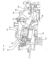
- Fig. 1 is a constructional view of a gas turbine combustor showing entire portions of the embodiments according to the present invention.
- Fig. 2 is a cross sectional view showing a fitting state of a rectifier tube of gas turbine combustor of a first embodiment.
- Fig. 3 is a cross sectional view taken on line A-A of Fig. 2.
- Fig. 4 is a perspective view of the rectifier tube of Fig. 2.
- Fig. 5 is a cross sectional view of an example where the rectifier tube of the first embodiment is applied to another type, or a hat top type, of combustor.
- Fig. 6 is a cross sectional view of another example where the rectifier tube of the first embodiment is applied to still another type of combustor.
- Fig. 7 is a side view of an inner tube portion of combustor of a second embodiment according to the present invention.
- Fig. 8 is a cross sectional view showing arrangement of air holes of the inner tube, wherein Fig. 8(a) is a view taken on line B-B of Fig. 7 and Fig. 8(b) is a view showing a modified example of the air holes.
- Fig. 9 is a cross sectional view taken on line C-C of Fig. 8(b).
- Fig. 10 is a graph showing a relation between smoke visibility and load as an effect of the second embodiment as compared with the prior art case.
- Fig. 11 is a partial cross sectional view of a main swirler of combustor of a third embodiment according to the present invention.
- Fig. 12 is an enlarged view of portion D of Fig. 11.
- Fig. 13 is partial view seen from plane E-E of Fig. 11.
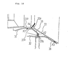
- Fig. 14 is a detailed view of portion F of Fig. 13.
- Fig. 15 is a cross sectional side view showing a fitting portion of a pilot cone of a fourth embodiment according to the present invention.
- Fig. 16 is a detailed view of portion G of Fig. 15.
- Fig. 17 is an enlarged detailed view of welded fitting structures of pilot cones, wherein Fig. 17(a) is of a prior art and Fig. 17(b) is of the fourth embodiment.
- Fig. 18 is a cross sectional view of a steam cooled structure of a combustor tail tube outlet portion of a fifth embodiment according to the present invention.
- Fig. 19 is a conceptual cross sectional view of a combustor of a sixth embodiment according to the present invention.
- Fig. 20 is a structural arrangement view of a representative gas turbine combustor and surrounding portions thereof in the prior art.
- Fig. 21 is an enlarged structural arrangement view of the gas turbine combustor of Fig. 20.
- Fig. 22 is a cross sectional view of a top hat type fuel nozzle portion of a prior art gas turbine.
- Fig. 23 is a side view of an inner tube portion of the combustor of Fig. 20.
- Fig. 24 is a cross sectional side view showing a swirler portion and a pilot cone portion in the prior art combustor.
- Fig. 25 is a partial view seen from plane H-H of Fig. 24.
- Fig. 26 is a partial detailed cross sectional view of a fitting portion of the pilot cone portion of Fig. 24.
- Fig. 27 is an explanatory view showing a tail tube cooling structure in a representative gas turbine combustor in the prior art, wherein Fig. 27(a) is an entire view, Fig. 27(b) is a perspective view showing a tail tube wall and Fig. 27(c) is a cross sectional view taken on line J-J of Fig. 27(b).
- Fig. 28 is a view seen from plane K-K of Fig. 27(a).
- Fig. 29 is a cross sectional view taken on line L-L of Fig. 28.
- Fig. 30 is a conceptual view of a two stage combustion type gas turbine combustor in the prior art.
- FIG. 1 shows an entire construction thereof.
- a (X-1) portion as a first embodiment
- a (X-2) portion as a second embodiment
- a (X-3) portion as a third embodiment
- a (X-4) portion as a fourth embodiment
- a (X-5) portion as a fifth embodiment
- a case to solve a combustion vibration problem as a sixth embodiment will be described sequentially below.
- Fig. 2 is a cross sectional view showing a fitting state of a rectifier tube of gas turbine combustor of the first embodiment
- Fig. 3 is a cross sectional view taken on line A-A of Fig. 2
- Fig. 4 is a perspective view of the rectifier tube of Fig. 2.
- a combustor 20 is contained in a turbine cylinder 50 and a plurality of stays 25 are fitted to around an outer periphery of an inner tube 28 with a predetermined interval being kept between each of the stays 25.
- a rectifier tube 11 is provided so as to surround and cover the stays 25 with a predetermined space being kept between itself and the inner tube 28 or the stays 25, said rectifier tube 11 at its fitting flange 5 being fitted fixedly by a bolt 6 to the turbine cylinder 50 side near end portions of the stays 25.
- the rectifier tube 11 is made by combining a cylinder 1 and a cylinder 2 both of a semi-circular cross sectional shape.
- the cylinder 1 is provided with flanges 3a, 3b, 3c, 3d (see Fig. 2) and the cylinder 2 is likewise provided with flanges 4a, 4b, 4c, 4d (4b and 4d are omitted in the illustration).
- These flanges are jointed together by bolts and nuts 7 to form the rectifier tube 11 of a circular cross sectional shape, wherein the flanges 3a and 4a, 3b and 4b, 3c and 4c, 3d and 4d are jointed together, respectively.
- the fitting flange 5 of the rectifier tube 11 is made in plural pieces arranged around one end of the rectifier tube 11 of the cylindrical shape, as shown in Fig. 3.
- the other end of the rectifier tube 11 opens as an opening of air inflow side.
- the fitting flange 5 side of the rectifier tube 11 opens also and main fuel nozzles 21 and a pilot fuel nozzle 22 are inserted through this opening portion.
- An outside view of only the rectifier tube 11 so constructed is shown in Fig. 4.
- air 40a, 40b coming from a compressor flows around the inner tube 28 of the combustor 20 through the predetermined space between the inner tube 28 and the rectifier tube 11 and is turned to be rectified by and around a sloping portion lla of the rectifier tube 11 wherein a diameter of the rectifier tube 11 contracts gradually along the air flow direction.
- the air 40a, 40b so rectified flows through gaps formed by the stays 25 to flow into the inner tube 28 uniformly.
- the air flowing around the combustor 20 flows in through the gaps of the stays 25 from a comparatively wide space formed between an inner wall of the turbine cylinder 50 and the combustor 20 and there is a wide space or narrow space in that space according to the place where the air flows, hence the air hardly flows uniformly therein.
- the rectifier tube 11 there is covered and kept the predetermined space by the rectifier tube 11 around the gaps of the stays 25 through which the air flows and the air whose pressure and velocity are kept constant flows into this space to further flow into the combustor 20 through the gaps of the stays 25, and further the air flow is rectified smoothly of its flow direction by the sloping portion of the rectifier tube 11 to flow into the combustor 20 uniformly, thus there occurs no biased flow of the air coming into the inner tube 28 and a uniform fuel concentration is attained at nozzle outlet portions of the combustor 20, thereby NO x production can be suppressed.
- Fig. 5 is a cross sectional view of an example where the rectifier tube 11 of the first embodiment is applied to another type, or a hat top type, of combustor.
- an outer tube casing 51 is provided projecting toward outside from a turbine casing 50 to form a fitting portion of an inner tube of the combustor.
- Such a combustor fitting structure is generally called a top hat type, wherein stays 25 support the inner tube 28 around main fuel nozzles 21 of the combustor and the outer tube casing 51 and an outer tube casing cover 51a surround to cover the stays 25.
- Such outer tube casing 51 is arranged projecting around a rotor in the same number of pieces as the combustor to form an extension portion of the turbine casing 50.
- the rectifier tube 11 is of a cylindrical shape divided into two portions as mentioned above.
- the rectifier tube 11 is provided with a plurality of fitting flanges 5 arranged circularly with a predetermined interval between each of the fitting flanges 5 and is fitted to an inner tube fitting flange 52 by bolts 6 via the fitting flanges 5.
- a sloping portion lla is formed so as to connect to the fitting flanges 5.
- the rectifier tube 11 is provided coaxially with a combustor central axis 60 and covers an air intake space keeping a gap so as not to come in contact with an inner wall surface of the outer tube casing 51 and keeping a uniform dimension of space around the stays 25.
- air 80 coming from a compressor flows in through an opening portion of the rectifier tube 11 to become a uniform flow 80a in the space between the rectifier tube 11 and the inner tube 28 and then turns in the space formed by the sloping portion lla and the stays 25 to flow into the combustor as a turning flow 80b.
- this turning flow 80b as the uniform flow 80a comes in there along the sloping portion lla of the rectifier tube 11, the flow turns smoothly to enter swirler portions in the space of the combustor, thereby a uniform swirled flow is produced and combustion performance is enhanced.
- Fig. 6 is a cross sectional view of another example where the rectifier tube 11 of the first embodiment is applied to still another type of combustor wherein the top hat structural portion of the combustor is divided. That is, an outer tube casing 151 is fitted with an outer tube casing cover 151a detachably by a bolt 152 so that when the bolt 152 is unfastened, the outer tube casing cover 152 together with the combustor may be taken out.
- the rectifier tube 11 is constructed to be fitted to the outer tube casing cover 151a via a fitting flange 5 and an inner tube fitting flange 52 integrally by a bolt 16.
- this construction there is needed no exclusive bolt for fitting the rectifier tube 11, thereby the structure of the fitting portion can be simplified.
- Other portions of the construction being same as those of Fig. 5, same effect as that of the example of Fig. 5 can be obtained.
- Fig. 7 is a side view of an inner tube portion of combustor of the second embodiment.
- a high temperature combustion gas 161 flows into an inner tube 28, said high temperature combustion gas being produced by combustion of fuel injected from a pilot fuel nozzle and main fuel nozzles and air.
- air holes 10-1 on an upstream side of the inner tube 28, said air holes 10-1 having six pieces of air holes arranged with equal intervals around the inner tube 28.
- air holes 10-2 downstream of the air holes 10-1, having six pieces of air holes with equal intervals.
- air holes 10-1, 10-2 are same as that of the prior art case shown in Fig. 23.
- air holes 10-3 on a downstream side of the inner tube 28 have only three pieces of air holes, less than six in the prior art case, around the inner tube 28.
- Fig. 8 is a cross sectional view showing arrangement of the air holes 10-3, wherein Fig. 8(a) is a view taken on line B-B of Fig. 7 and Fig. 8(b) is a view showing a modified example of the air holes 10-3.
- Fig. 8(a) there are provided three pieces of air holes 10-3a, 10-3b, 10-3c with equal intervals in the circumferential surface of the inner tube 28.
- Fig. 9 is a cross sectional view taken on line C-C of Fig. 8(b).
- the plug 14 being of a diameter which is slightly smaller than a hole diameter of the air hole 10-3b, has a flange 14a around a peripheral portion thereof and is fitted in the air hole 10-3b to be fixed by welding, etc. for close of the hole.
- the inner tube as existing can be used as it is and, when so modified, can have the construction of the present second embodiment easily.
- the air entering the combustor 20 comprises three portions, like in the prior art case, that is, the air used for combustion at the nozzle portion, the air entering the inner tube for cooling thereof through the small cooling holes and the air flowing into the inner tube through air holes 10-1, 10-2, 10-3.
- the total quantity of the air is 100%
- the quantity of the air flowing through the air holes 10-1, 10-2 is about 14%, respectively, like in the prior art case, and that of the air flowing through the air holes 10-3, having only the three holes as compared with the six holes in the prior art, is suppressed to about 7 to 12%.
- the respective air quantities of the air holes 10-1, 10-2, 10-3 are expressed in ratio, it is approximately 1:1:(0.5 to 0.85), and as compared with the ratio in the prior art of 1:1:(1.3 to 1.4), the air quantity entering the inner tube from the air holes 10-3 of the downstream side of the inner tube is reduced approximately to the half.
- an appropriate air quantity is realized such that while the air 131 entering through the air holes 10-3 of the downstream side of the inner tube is sufficient to be used for combustion of carbon remaining unburnt in the high temperature combustion gas 161, it is not so much as to cool the high temperature combustion gas 161.
- combustion efficiency is enhanced and occurrence of a dark colored smoke in the exhaust gas can be prevented.
- Fig. 10 is a graph showing a relation between smoke visibility and load as an effect of the second embodiment as compared with the prior art case.
- the horizontal axis shows load and the vertical axis shows value of a level of smoke visibility (BSN).
- BSN level of smoke visibility
- smoke color X 1 of the combustor of the present embodiment is thinner than that X 2 of the combustor in the prior art shown in Fig. 23 and there is obtained an effect to suppress occurrence of the smoke.
- Fig. 11 is a partial cross sectional view of a main swirler of combustor of the third embodiment.
- a combustor 20 in its central portion has a pilot swirler 31 and a pilot cone 33 arranged at an end portion thereof and eight pieces of main swirlers 32 are arranged around the pilot swirler 31.
- These swirlers 31, 32 are fitted to a base plate 34 of circular shape and the base plate 34 has its circumferential periphery welded to an inner wall of the combustor 20. This structure is same as that existing in the prior art.
- a block 17 is fitted to an outer circumferential surface of an end portion of the main swirler 32 and the main swirler 32 is fixed to the inner wall of an end portion of the combustor 20 via the block 17, wherein the block 17 is fixed to the inner wall of the combustor 20 by a bolt 12, which passes through the wall of the combustor from outside, via a washer 13.
- Fig. 12 is an enlarged view of portion D of Fig. 11.
- the block 17 is fitted to the main swirler 32 by welding.
- a fitting seat 36a is formed by cladding welding on the inner wall of an end portion 36 of the combustor 20 and a recess portion 36b for receiving the washer 13 is formed in an outer wall of the combustor 20 at a position corresponding to the fitting seat 36a.
- a bolt hole is bored there and the bolt 12 is screwed into the block 17 for fixing thereof via the washer 13, thereby the main swirler 32 is fixed to the combustor 20.
- Fig. 13 is a partial view seen from plane E-E of Fig. 11.
- the block 17 is fitted by welding to the outer circumferential surface each of the main swirlers 32 arranged in eight pieces and each of the blocks 17 is fixed to the wall of the end portion 36 of the combustor 20 by two bolts 12.
- the two bolts 17 are screwed into the block 17 via one common washer 13.
- Fig. 14 is a detailed view of portion F of Fig. 13, wherein the bolts 12 and the washer 13 are shown being enlarged.
- the recess portion 36b is formed not in a curved form but in a linear form in the outer circumferential surface of the end portion 36 of the combustor 20 and the washer 13 is made in a flat plate of linear shape.
- the two bolts 12 are inserted into bolt holes 36c which are bored in parallel with each other to be screwed into the block 17 for fixing thereof and thus for fixing the main swirler 32 to the combustor 20.
- An anti-rotation welding 18 is applied to the bolt 12 for preventing rotation or loosening thereof.
- the main swirler 32 is fixed to the combustor 20 by the bolt 12 via the washer 13 and the block 17 fixed to the main swirler 32, thereby accuracy of the assembling is enhanced, strain due to welding does not occur and welding work in the narrow space becomes unnecessary.
- the washer 13 of flat plate shape makes contact with the recess portion 36b and the two bolts 12 fixes the main swirler 32 to the combustor 20, thereby no loosening of the bolt 12 occur and a precise positioning becomes possible. Further, maintenance of replacement of parts. etc. becomes simple, so that all the mentioned problems are improved.
- Fig. 15 is a cross sectional side view showing a fitting portion of a pilot cone in the combustor in contrast with the prior art case shown in Fig. 24.
- Fig. 16 is a detailed view of portion G of Fig. 15 in contrast with the prior art case shown in Fig. 26.
- a pilot swirler 31, a pilot cone 33, a main swirler 32, a base plate 39, a fitting member 39b and a cone ring 38, respectively, have the same functions as those of the prior art shown in Figs. 24 and 26, hence same reference numerals are used with description thereon being omitted, and featured portions of the present invention being configuration portions shown by numerals 31a, 33a and welded portions of X 1 to X 4 , they will be described in detail below.
- a pilot swirler end portion 31a while it is structured in the prior art to be inserted into an end portion of the pilot cone 33 in contact with an inner circumferential surface of the pilot cone 33, that of the present invention is structured to be inserted into the cylindrical portion 39a of the base plate 39.
- a pilot cone end portion 33a is made shorter as compared with the prior art case and an outer diameter of the pilot cone end portion 33a is made approximately same as that of the pilot swirler end portion 31a so that both ends of the pilot cone end portion 33a and the pilot swirler end portion 31a are welded together in contact with each other.
- the pilot swirler 31 is first inserted into the cylindrical portion 39a of the base plate 39 to be fixed to an end of the cylindrical portion 39a by welding X 1 done along the circumferential direction. Then, the cone ring 38 is fitted to the fitting member 39b, which is made integrally with the base plate 39, by welding X 2 done along the circumferential direction. Then, while the pilot cone end portion 33a and the pilot swirler end portion 31a make contact with each other, the pilot cone 33 is fitted to the cone ring 38 by welding X 3 and thereafter the pilot cone end portion 33a and the pilot cone 33 are jointed together by welding X 4 which is done from inside of the pilot cone 33 along the circumferential direction.
- the welding X 3 , X 4 may be done in the reverse order, that is, the welding X 4 is earlier and the welding X 3 is later and also that a black arrow in Fig. 16 shows a direction in which the welding X 4 is done.
- the welding X 4 is removed from inside of the pilot cone 33 and the welding X 3 at a pilot cone outlet is also removed, thereby the pilot cone 33 can be detached easily.
- accuracy of the welded structure is enhanced, thereby welding strength can be enhanced and workability in the repairing can be improved remarkably.
- Fig. 17 is an enlarged detailed view of the welded fitting structures of the pilot cones of the prior art and of the present fourth embodiment, wherein Fig. 17(a) is of the prior art and Fig. 17(b) is of the fourth embodiment.
- the pilot cone end portion 33a is made long enough to be inserted into the cylindrical portion 39a of the base plate 39 in the prior art, that 33a of the present embodiment is made shorter to abut on the pilot swirler end portion 31a.
- the pilot cone 33 of Fig. 17(b) is supported by the base plate 39 via the welding X 4 of the pilot swirler 31 and it is understood that detachment of the pilot cone 33 is done easily if the welding X 4 is removed by the work done from inside of the pilot cone 33, as shown by a black arrow of Fig. 17(b).
- the welded structure is employed such that the pilot swirler 31 is first fitted to the base plate and the pilot cone 33 is fitted thereafter, and also the welding X 4 therefor is done from inside of the pilot cone 33, thereby repairing work and detachment of the pilot cone 33 become easy to improve the workability remarkably.
- a lot of labor and time for repairing can be saved, accuracy of the welding is enhanced as well and strain due to the thermal stress can be suppressed to the minimum.
- Fig. 18 is a cross sectional view of a steam cooled structure of a combustor tail tube outlet portion of the fifth embodiment. This steam cooled structure is applicable to the outlet portion of the tail tube 24 shown in Fig. 27, and the structure of Fig. 18 is shown in contrast with that of the prior art shown in Fig. 29.
- a multiplicity of steam passages 150 are provided in a wall 20a of the tail tube outlet portion and a cavity 75 is formed in an entire inner circumferential peripheral portion of a flange 71 of the tail tube outlet portion.
- a manifold 73 and a hollow 77 are formed being covered circumferentially by a covering member 72 between an outer surface portion of the wall 20a of the tail tube outlet portion and the flange 71 and being partitioned by a rib 76 between each other.
- the manifold 73 communicates with a cooling steam supply pipe (not shown) and the hollow 77 has air layer formed therein.
- cooling steam 132 supplied into the manifold 73 from the cooling steam supply pipe flows into the steam passages 150 through a steam supply hole 74 to cool the wall 20a which is exposed to a high temperature combustion gas of about 1500°C.
- the steam entering the cavity 75 cools end portions 20b, 20c.
- the end portion 20b cooled by the steam in the cavity 75 is exposed on a side surface of the flange 71 to air of about 400 to 450°C in a turbine cylinder.
- the end portion 20c is exposed to the air layer in the hollow 77 and is not directly exposed to the cooling steam 132. While this end portion 20c is directly exposed to the cooling steam 132 to be cooled excessively in the prior art, such an excessive cooling is prevented in the present fifth embodiment.
- the wall 20a of the tail tube outlet portion to be directly exposed to the high temperature combustion gas 161 is cooled sufficiently by the cooling steam 132 supplied into the steam passages 150 from the manifold 73 through the steam supply hole 74.
- the end portion 20c which is not directly exposed to the high temperature combustion gas 161 is not cooled.
- This end portion 20c makes contact with the air layer in the hollow 77 and is not cooled excessively.
- a gas turbine combustor of a sixth embodiment will be described with reference to Fig. 19.
- a combustor 20 is generally formed in a cylindrical shape and a pilot fuel nozzle 22 for supplying pilot fuel is provided in a liner 212 along a central axis O of the combustor 20.
- a pilot air supply passage 216 is provided around the pilot fuel nozzle 22 and a pilot swirler 31 for holding pilot flame is provided in the pilot air supply passage 216.
- the pilot fuel nozzle 22, the pilot air supply passage 216 and the pilot swirler 31 compose a pilot burner. Downstream of the pilot air supply passage 216, there is provided a pilot cone 33 for forming a pilot combustion chamber 224.
- a main fuel nozzle 21 for supplying main fuel and a main air supply passage 222 are provided around the pilot air supply passage 216.
- a main swirler 32 is provided in the main air supply passage 222.
- the main fuel nozzle 21, the main air supply passage 222 and the main swirler 32 compose a main burner.
- an exhaust gas supply passage 218 as a supply passage of shield gas.
- a sub-cone 226 is provided coaxially with the pilot cone 33.
- Numeral 218a designates a swirler provided in the exhaust gas supply passage 218.
- Pilot air supplied from the pilot air supply passage 216 enters the pilot combustion chamber 224 to flow surrounding pilot fuel supplied from the pilot fuel nozzle 22, thereby the pilot fuel together with the pilot air burns to form the pilot flame (a white arrow 230) comprising diffusion flame.
- Main fuel supplied from the main fuel nozzle 21 and main air supplied from the main air supply passage 222 are mixed together in a mixing chamber 228 downstream thereof to form a premixture shown by arrow 232. This premixture 232 comes in contact with the pilot flame 230 to form premixture flame as main flame 234.
- exhaust gas produced by the combustion is supplied into a gas turbine (not shown) provided downstream of the combustor 20 for driving the gas turbine. After having driven the gas turbine, the exhaust gas is mostly discharged into the air, but a portion thereof is recirculated into the exhaust gas supply passage 218 of the combustor 20 via a recirculation system including an exhaust gas compressor, etc. (not shown).
- the exhaust gas 236 supplied from the exhaust gas supply passage 218 flows through an exhaust gas leading portion as a leading portion of shield gas formed between the pilot cone 33 and the sub-cone 226 to be supplied between the pilot flame 230 and the premixture 232.
- mutual contact of the pilot flame 230 and the premixture 232 is suppressed by the exhaust gas 236 so supplied, thereby combustion velocity of the main flame 234 is reduced and the main flame 234 becomes longer in the combustor axial direction or in the main flow direction.
- combustion energy concentration released by the main flame 234 or cross sectional combustion load of the combustor becomes reduced, exciting force of the combustion vibration is reduced and combustion vibration is suppressed.
- oxygen concentration in the main flame 234 is reduced and flame temperature is reduced, thereby NO x quantity produced is reduced.
- exhaust gas of the gas turbine is described in the present embodiment, the invention is not limited thereto but exhaust gas from other machinery or equipment may be used, or inert gas, such as nitrogen, supplied from other facilities may be used in place of the exhaust gas.
- inert gas such as nitrogen
- the point therefor is to use gas which is inert with respect to combustion reaction so as to be able to prevent direct contact of the mixture and the pilot flame and to elongate the premixture flame in the main flow direction in the combustor.
Landscapes
- Engineering & Computer Science (AREA)
- Chemical & Material Sciences (AREA)
- Combustion & Propulsion (AREA)
- Mechanical Engineering (AREA)
- General Engineering & Computer Science (AREA)
- Turbine Rotor Nozzle Sealing (AREA)
Applications Claiming Priority (4)
| Application Number | Priority Date | Filing Date | Title |
|---|---|---|---|
| JP10322630A JP2000146183A (ja) | 1998-11-12 | 1998-11-12 | ガスタービン燃焼器 |
| JP32263098 | 1998-11-12 | ||
| JP34883898 | 1998-12-08 | ||
| JP34883898A JP3697093B2 (ja) | 1998-12-08 | 1998-12-08 | ガスタービン燃焼器 |
Publications (3)
| Publication Number | Publication Date |
|---|---|
| EP1001224A2 true EP1001224A2 (fr) | 2000-05-17 |
| EP1001224A3 EP1001224A3 (fr) | 2002-03-06 |
| EP1001224B1 EP1001224B1 (fr) | 2006-03-22 |
Family
ID=26570886
Family Applications (1)
| Application Number | Title | Priority Date | Filing Date |
|---|---|---|---|
| EP99121873A Expired - Lifetime EP1001224B1 (fr) | 1998-11-12 | 1999-11-04 | Chambre de combustion pour une turbine à gaz |
Country Status (4)
| Country | Link |
|---|---|
| US (2) | US6282886B1 (fr) |
| EP (1) | EP1001224B1 (fr) |
| CA (1) | CA2288555C (fr) |
| DE (1) | DE69930455T2 (fr) |
Cited By (5)
| Publication number | Priority date | Publication date | Assignee | Title |
|---|---|---|---|---|
| EP1211463A2 (fr) * | 2000-12-04 | 2002-06-05 | Mitsubishi Heavy Industries, Ltd. | Plaque à ailettes et chambre de combustion comprenant la plaque à ailettes |
| WO2003002913A1 (fr) * | 2001-06-27 | 2003-01-09 | Mitsubishi Heavy Industries, Ltd. | Dispositif combustor de turbine a gaz |
| EP2256413A1 (fr) * | 2009-05-27 | 2010-12-01 | Siemens Aktiengesellschaft | Brûleur, procédé de fonctionnement et procédé de montage |
| WO2010136287A2 (fr) * | 2009-05-27 | 2010-12-02 | Siemens Aktiengesellschaft | Brûleur, procédé d'utilisation et procédé d'assemblage |
| WO2012161609A1 (fr) * | 2011-05-25 | 2012-11-29 | General Electric Company | Dispositif de combustion à collecteur bidirectionnel pour amortissement dynamique |
Families Citing this family (38)
| Publication number | Priority date | Publication date | Assignee | Title |
|---|---|---|---|---|
| EP1270874B1 (fr) * | 2001-06-18 | 2005-08-31 | Siemens Aktiengesellschaft | Turbine à gaz avec un compresseur d'air |
| JP3986348B2 (ja) * | 2001-06-29 | 2007-10-03 | 三菱重工業株式会社 | ガスタービン燃焼器の燃料供給ノズルおよびガスタービン燃焼器並びにガスタービン |
| JP2003201863A (ja) * | 2001-10-29 | 2003-07-18 | Mitsubishi Heavy Ind Ltd | 燃焼器及びこれを備えたガスタービン |
| US7143583B2 (en) * | 2002-08-22 | 2006-12-05 | Hitachi, Ltd. | Gas turbine combustor, combustion method of the gas turbine combustor, and method of remodeling a gas turbine combustor |
| US6705087B1 (en) | 2002-09-13 | 2004-03-16 | Siemens Westinghouse Power Corporation | Swirler assembly with improved vibrational response |
| JP3951909B2 (ja) * | 2002-12-12 | 2007-08-01 | 株式会社日立製作所 | ガスタービン燃焼器 |
| US7104066B2 (en) * | 2003-08-19 | 2006-09-12 | General Electric Company | Combuster swirler assembly |
| CN100590359C (zh) * | 2004-03-03 | 2010-02-17 | 三菱重工业株式会社 | 燃烧器 |
| US7647779B2 (en) * | 2005-04-27 | 2010-01-19 | United Technologies Corporation | Compliant metal support for ceramic combustor liner in a gas turbine engine |
| FR2885201B1 (fr) * | 2005-04-28 | 2010-09-17 | Snecma Moteurs | Chambre de combustion aisement demontable a performance aerodynamique amelioree |
| JP2007162998A (ja) * | 2005-12-13 | 2007-06-28 | Kawasaki Heavy Ind Ltd | ガスタービンエンジンの燃料噴霧装置 |
| US7540153B2 (en) * | 2006-02-27 | 2009-06-02 | Mitsubishi Heavy Industries Ltd. | Combustor |
| US7540152B2 (en) * | 2006-02-27 | 2009-06-02 | Mitsubishi Heavy Industries, Ltd. | Combustor |
| US7523614B2 (en) * | 2006-02-27 | 2009-04-28 | Mitsubishi Heavy Industries, Ltd. | Combustor |
| US7770395B2 (en) * | 2006-02-27 | 2010-08-10 | Mitsubishi Heavy Industries, Ltd. | Combustor |
| US7564329B2 (en) * | 2006-07-28 | 2009-07-21 | Cooper Technologies Company | Ground fault circuit interrupter device |
| FR2911667B1 (fr) * | 2007-01-23 | 2009-10-02 | Snecma Sa | Systeme d'injection de carburant a double injecteur. |
| JP4421620B2 (ja) * | 2007-02-15 | 2010-02-24 | 川崎重工業株式会社 | ガスタービンエンジンの燃焼器 |
| JP2008261605A (ja) * | 2007-04-13 | 2008-10-30 | Mitsubishi Heavy Ind Ltd | ガスタービン燃焼器 |
| JP5276345B2 (ja) * | 2008-03-28 | 2013-08-28 | 三菱重工業株式会社 | ガスタービン及びガスタービンの燃焼器挿入孔形成方法 |
| CH699309A1 (de) | 2008-08-14 | 2010-02-15 | Alstom Technology Ltd | Thermische maschine mit luftgekühlter, ringförmiger brennkammer. |
| US20100175380A1 (en) | 2009-01-13 | 2010-07-15 | General Electric Company | Traversing fuel nozzles in cap-less combustor assembly |
| US8590315B2 (en) * | 2010-06-01 | 2013-11-26 | General Electric Company | Extruded fluid manifold for gas turbomachine combustor casing |
| US8733108B2 (en) * | 2010-07-09 | 2014-05-27 | General Electric Company | Combustor and combustor screech mitigation methods |
| US8991187B2 (en) | 2010-10-11 | 2015-03-31 | General Electric Company | Combustor with a lean pre-nozzle fuel injection system |
| US9291102B2 (en) | 2011-09-07 | 2016-03-22 | Siemens Energy, Inc. | Interface ring for gas turbine fuel nozzle assemblies |
| JP5804872B2 (ja) * | 2011-09-27 | 2015-11-04 | 三菱日立パワーシステムズ株式会社 | 燃焼器の尾筒、これを備えているガスタービン、及び尾筒の製造方法 |
| KR101614636B1 (ko) * | 2011-11-16 | 2016-04-21 | 미츠비시 히타치 파워 시스템즈 가부시키가이샤 | 가스 터빈 연소기 |
| EP2799773B1 (fr) * | 2011-12-27 | 2017-04-19 | NGK Insulators, Ltd. | Procédé de fonctionnement d'un appareil de combustion |
| US20130180261A1 (en) * | 2012-01-13 | 2013-07-18 | General Electric Company | Combustor and method for reducing thermal stresses in a combustor |
| WO2013128572A1 (fr) * | 2012-02-28 | 2013-09-06 | 三菱重工業株式会社 | Brûleur, et turbine à gaz |
| US20130276450A1 (en) * | 2012-04-24 | 2013-10-24 | General Electric Company | Combustor apparatus for stoichiometric combustion |
| US10100741B2 (en) * | 2012-11-02 | 2018-10-16 | General Electric Company | System and method for diffusion combustion with oxidant-diluent mixing in a stoichiometric exhaust gas recirculation gas turbine system |
| JP6318443B2 (ja) * | 2013-01-22 | 2018-05-09 | 三菱日立パワーシステムズ株式会社 | 燃焼器、及び回転機械 |
| CN104807044B (zh) * | 2015-05-11 | 2017-03-08 | 北京航空航天大学 | 一种出口带旋流叶片的液化气燃烧室 |
| JP6895867B2 (ja) * | 2017-10-27 | 2021-06-30 | 三菱パワー株式会社 | ガスタービン燃焼器、ガスタービン |
| CN111805078B (zh) * | 2020-07-23 | 2021-12-21 | 哈尔滨汽轮机厂有限责任公司 | 一种300mw级重型燃机喷嘴旋流器组件的制造方法 |
| CN115899769A (zh) * | 2022-10-17 | 2023-04-04 | 南京航空航天大学 | 一种内级凹腔与外级旋流耦合的燃烧室 |
Citations (6)
| Publication number | Priority date | Publication date | Assignee | Title |
|---|---|---|---|---|
| US4129985A (en) * | 1975-11-17 | 1978-12-19 | Kawasaki Jukogyo Kabushiki Kaisha | Combustor device of gas turbine engine |
| US4704869A (en) * | 1983-06-08 | 1987-11-10 | Hitachi, Ltd. | Gas turbine combustor |
| EP0550218A1 (fr) * | 1991-12-30 | 1993-07-07 | General Electric Company | Chambre de combustion pour turbine à gaz |
| US5363653A (en) * | 1992-07-08 | 1994-11-15 | Man Gutehoffnungshutte Ag | Cylindrical combustion chamber housing of a gas turbine |
| US6026645A (en) * | 1998-03-16 | 2000-02-22 | Siemens Westinghouse Power Corporation | Fuel/air mixing disks for dry low-NOx combustors |
| US6082111A (en) * | 1998-06-11 | 2000-07-04 | Siemens Westinghouse Power Corporation | Annular premix section for dry low-NOx combustors |
Family Cites Families (7)
| Publication number | Priority date | Publication date | Assignee | Title |
|---|---|---|---|---|
| US4852355A (en) * | 1980-12-22 | 1989-08-01 | General Electric Company | Dispensing arrangement for pressurized air |
| JPH0752014B2 (ja) * | 1986-03-20 | 1995-06-05 | 株式会社日立製作所 | ガスタ−ビン燃焼器 |
| US5220795A (en) * | 1991-04-16 | 1993-06-22 | General Electric Company | Method and apparatus for injecting dilution air |
| JP3197103B2 (ja) | 1993-03-08 | 2001-08-13 | 三菱重工業株式会社 | 予混合気の燃焼方法 |
| JPH0921531A (ja) | 1995-07-05 | 1997-01-21 | Mitsubishi Heavy Ind Ltd | ガスタービンの予混合燃焼器 |
| JP3392633B2 (ja) * | 1996-05-15 | 2003-03-31 | 三菱重工業株式会社 | 燃焼器 |
| US6038861A (en) * | 1998-06-10 | 2000-03-21 | Siemens Westinghouse Power Corporation | Main stage fuel mixer with premixing transition for dry low Nox (DLN) combustors |
-
1999
- 1999-11-04 EP EP99121873A patent/EP1001224B1/fr not_active Expired - Lifetime
- 1999-11-04 DE DE69930455T patent/DE69930455T2/de not_active Expired - Fee Related
- 1999-11-04 CA CA002288555A patent/CA2288555C/fr not_active Expired - Fee Related
- 1999-11-10 US US09/437,146 patent/US6282886B1/en not_active Expired - Lifetime
-
2001
- 2001-05-23 US US09/862,468 patent/US6327861B2/en not_active Expired - Fee Related
Patent Citations (6)
| Publication number | Priority date | Publication date | Assignee | Title |
|---|---|---|---|---|
| US4129985A (en) * | 1975-11-17 | 1978-12-19 | Kawasaki Jukogyo Kabushiki Kaisha | Combustor device of gas turbine engine |
| US4704869A (en) * | 1983-06-08 | 1987-11-10 | Hitachi, Ltd. | Gas turbine combustor |
| EP0550218A1 (fr) * | 1991-12-30 | 1993-07-07 | General Electric Company | Chambre de combustion pour turbine à gaz |
| US5363653A (en) * | 1992-07-08 | 1994-11-15 | Man Gutehoffnungshutte Ag | Cylindrical combustion chamber housing of a gas turbine |
| US6026645A (en) * | 1998-03-16 | 2000-02-22 | Siemens Westinghouse Power Corporation | Fuel/air mixing disks for dry low-NOx combustors |
| US6082111A (en) * | 1998-06-11 | 2000-07-04 | Siemens Westinghouse Power Corporation | Annular premix section for dry low-NOx combustors |
Cited By (14)
| Publication number | Priority date | Publication date | Assignee | Title |
|---|---|---|---|---|
| EP1211463A2 (fr) * | 2000-12-04 | 2002-06-05 | Mitsubishi Heavy Industries, Ltd. | Plaque à ailettes et chambre de combustion comprenant la plaque à ailettes |
| EP1211463A3 (fr) * | 2000-12-04 | 2003-07-23 | Mitsubishi Heavy Industries, Ltd. | Plaque à ailettes et chambre de combustion comprenant la plaque à ailettes |
| WO2003002913A1 (fr) * | 2001-06-27 | 2003-01-09 | Mitsubishi Heavy Industries, Ltd. | Dispositif combustor de turbine a gaz |
| US7032386B2 (en) | 2001-06-27 | 2006-04-25 | Mitsubishi Heavy Industries, Ltd. | Gas turbine combustor |
| WO2010136287A3 (fr) * | 2009-05-27 | 2012-05-18 | Siemens Aktiengesellschaft | Brûleur, procédé d'utilisation et procédé d'assemblage |
| WO2010136287A2 (fr) * | 2009-05-27 | 2010-12-02 | Siemens Aktiengesellschaft | Brûleur, procédé d'utilisation et procédé d'assemblage |
| EP2256413A1 (fr) * | 2009-05-27 | 2010-12-01 | Siemens Aktiengesellschaft | Brûleur, procédé de fonctionnement et procédé de montage |
| CN102597632A (zh) * | 2009-05-27 | 2012-07-18 | 西门子公司 | 燃烧器、操作方法和组装方法 |
| RU2541482C2 (ru) * | 2009-05-27 | 2015-02-20 | Сименс Акциенгезелльшафт | Горелка и газовая турбина, содержащая такую горелку |
| US9127842B2 (en) | 2009-05-27 | 2015-09-08 | Siemens Aktiengesellschaft | Burner, operating method and assembly method |
| CN102597632B (zh) * | 2009-05-27 | 2016-08-24 | 西门子公司 | 燃烧器、操作方法和组装方法 |
| WO2012161609A1 (fr) * | 2011-05-25 | 2012-11-29 | General Electric Company | Dispositif de combustion à collecteur bidirectionnel pour amortissement dynamique |
| CN103717970A (zh) * | 2011-05-25 | 2014-04-09 | 通用电气公司 | 用于对动力进行阻尼的带有双向歧管的燃烧器 |
| CN103717970B (zh) * | 2011-05-25 | 2017-03-22 | 通用电气公司 | 用于对动力进行阻尼的带有双向歧管的燃烧器 |
Also Published As
| Publication number | Publication date |
|---|---|
| DE69930455D1 (de) | 2006-05-11 |
| US20010020364A1 (en) | 2001-09-13 |
| DE69930455T2 (de) | 2006-11-23 |
| EP1001224B1 (fr) | 2006-03-22 |
| CA2288555A1 (fr) | 2000-05-12 |
| US6282886B1 (en) | 2001-09-04 |
| US6327861B2 (en) | 2001-12-11 |
| EP1001224A3 (fr) | 2002-03-06 |
| CA2288555C (fr) | 2007-01-23 |
Similar Documents
| Publication | Publication Date | Title |
|---|---|---|
| EP1001224B1 (fr) | Chambre de combustion pour une turbine à gaz | |
| US8919673B2 (en) | Apparatus and method for a fuel nozzle | |
| US7080515B2 (en) | Gas turbine can annular combustor | |
| US9534787B2 (en) | Micromixing cap assembly | |
| EP1143201B1 (fr) | Système de refroidissement d'une chambre de combustion de turbine à gaz | |
| JP7146442B2 (ja) | 二重燃料噴射器およびガスタービン燃焼器での使用方法 | |
| US6442940B1 (en) | Gas-turbine air-swirler attached to dome and combustor in single brazing operation | |
| US8495881B2 (en) | System and method for thermal control in a cap of a gas turbine combustor | |
| US8756934B2 (en) | Combustor cap assembly | |
| US6546732B1 (en) | Methods and apparatus for cooling gas turbine engine combustors | |
| KR20180126043A (ko) | 축방향 연료 다단화를 이용하는 분할형 환형 연소 시스템 | |
| US20140182294A1 (en) | Gas turbine combustor | |
| US8528839B2 (en) | Combustor nozzle and method for fabricating the combustor nozzle | |
| US20070051110A1 (en) | Igniter tube and method of assembling same | |
| US9297533B2 (en) | Combustor and a method for cooling the combustor | |
| CA2383463C (fr) | Techniques et dispositifs de refroidissement de chambre a combustion de turbine a gaz | |
| CN103032895A (zh) | 用于冷却多管燃料喷嘴的系统 | |
| US8261554B2 (en) | Fuel nozzle tip assembly | |
| JP5791302B2 (ja) | バーナ装置 | |
| US9157370B2 (en) | Burner assembly | |
| JP3697093B2 (ja) | ガスタービン燃焼器 | |
| US20080072602A1 (en) | Extended life fuel nozzle | |
| JP5718796B2 (ja) | シール部材を備えたガスタービン燃焼器 | |
| JP2011169579A (ja) | バーナ装置 |
Legal Events
| Date | Code | Title | Description |
|---|---|---|---|
| PUAI | Public reference made under article 153(3) epc to a published international application that has entered the european phase |
Free format text: ORIGINAL CODE: 0009012 |
|
| 17P | Request for examination filed |
Effective date: 19991201 |
|
| AK | Designated contracting states |
Kind code of ref document: A2 Designated state(s): AT BE CH CY DE DK ES FI FR GB GR IE IT LI LU MC NL PT SE Kind code of ref document: A2 Designated state(s): CH DE FR GB IT LI |
|
| AX | Request for extension of the european patent |
Free format text: AL;LT;LV;MK;RO;SI |
|
| PUAL | Search report despatched |
Free format text: ORIGINAL CODE: 0009013 |
|
| AK | Designated contracting states |
Kind code of ref document: A3 Designated state(s): AT BE CH CY DE DK ES FI FR GB GR IE IT LI LU MC NL PT SE |
|
| AX | Request for extension of the european patent |
Free format text: AL;LT;LV;MK;RO;SI |
|
| RIC1 | Information provided on ipc code assigned before grant |
Free format text: 7F 23R 3/46 A, 7F 23R 3/28 B, 7F 23R 3/10 B, 7F 23R 3/02 B, 7F 23R 3/60 B |
|
| AKX | Designation fees paid |
Free format text: CH DE FR GB IT LI |
|
| 17Q | First examination report despatched |
Effective date: 20041210 |
|
| GRAP | Despatch of communication of intention to grant a patent |
Free format text: ORIGINAL CODE: EPIDOSNIGR1 |
|
| GRAS | Grant fee paid |
Free format text: ORIGINAL CODE: EPIDOSNIGR3 |
|
| GRAA | (expected) grant |
Free format text: ORIGINAL CODE: 0009210 |
|
| AK | Designated contracting states |
Kind code of ref document: B1 Designated state(s): CH DE FR GB IT LI |
|
| PG25 | Lapsed in a contracting state [announced via postgrant information from national office to epo] |
Ref country code: LI Free format text: LAPSE BECAUSE OF FAILURE TO SUBMIT A TRANSLATION OF THE DESCRIPTION OR TO PAY THE FEE WITHIN THE PRESCRIBED TIME-LIMIT Effective date: 20060322 Ref country code: IT Free format text: LAPSE BECAUSE OF FAILURE TO SUBMIT A TRANSLATION OF THE DESCRIPTION OR TO PAY THE FEE WITHIN THE PRESCRIBED TIME-LIMIT;WARNING: LAPSES OF ITALIAN PATENTS WITH EFFECTIVE DATE BEFORE 2007 MAY HAVE OCCURRED AT ANY TIME BEFORE 2007. THE CORRECT EFFECTIVE DATE MAY BE DIFFERENT FROM THE ONE RECORDED. Effective date: 20060322 Ref country code: CH Free format text: LAPSE BECAUSE OF FAILURE TO SUBMIT A TRANSLATION OF THE DESCRIPTION OR TO PAY THE FEE WITHIN THE PRESCRIBED TIME-LIMIT Effective date: 20060322 |
|
| REG | Reference to a national code |
Ref country code: GB Ref legal event code: FG4D |
|
| REG | Reference to a national code |
Ref country code: CH Ref legal event code: EP |
|
| REF | Corresponds to: |
Ref document number: 69930455 Country of ref document: DE Date of ref document: 20060511 Kind code of ref document: P |
|
| REG | Reference to a national code |
Ref country code: CH Ref legal event code: PL |
|
| PLBE | No opposition filed within time limit |
Free format text: ORIGINAL CODE: 0009261 |
|
| STAA | Information on the status of an ep patent application or granted ep patent |
Free format text: STATUS: NO OPPOSITION FILED WITHIN TIME LIMIT |
|
| EN | Fr: translation not filed | ||
| 26N | No opposition filed |
Effective date: 20061227 |
|
| GBPC | Gb: european patent ceased through non-payment of renewal fee |
Effective date: 20061104 |
|
| PG25 | Lapsed in a contracting state [announced via postgrant information from national office to epo] |
Ref country code: GB Free format text: LAPSE BECAUSE OF NON-PAYMENT OF DUE FEES Effective date: 20061104 |
|
| PG25 | Lapsed in a contracting state [announced via postgrant information from national office to epo] |
Ref country code: FR Free format text: LAPSE BECAUSE OF FAILURE TO SUBMIT A TRANSLATION OF THE DESCRIPTION OR TO PAY THE FEE WITHIN THE PRESCRIBED TIME-LIMIT Effective date: 20070309 |
|
| PG25 | Lapsed in a contracting state [announced via postgrant information from national office to epo] |
Ref country code: FR Free format text: LAPSE BECAUSE OF FAILURE TO SUBMIT A TRANSLATION OF THE DESCRIPTION OR TO PAY THE FEE WITHIN THE PRESCRIBED TIME-LIMIT Effective date: 20060322 |
|
| PGFP | Annual fee paid to national office [announced via postgrant information from national office to epo] |
Ref country code: DE Payment date: 20081103 Year of fee payment: 10 |
|
| PG25 | Lapsed in a contracting state [announced via postgrant information from national office to epo] |
Ref country code: DE Free format text: LAPSE BECAUSE OF NON-PAYMENT OF DUE FEES Effective date: 20100601 |