EP1000472B1 - Verfahren und funkstation zur datenübertragung - Google Patents
Verfahren und funkstation zur datenübertragung Download PDFInfo
- Publication number
- EP1000472B1 EP1000472B1 EP98947312A EP98947312A EP1000472B1 EP 1000472 B1 EP1000472 B1 EP 1000472B1 EP 98947312 A EP98947312 A EP 98947312A EP 98947312 A EP98947312 A EP 98947312A EP 1000472 B1 EP1000472 B1 EP 1000472B1
- Authority
- EP
- European Patent Office
- Prior art keywords
- data
- midamble
- time slot
- radio
- symbols
- Prior art date
- Legal status (The legal status is an assumption and is not a legal conclusion. Google has not performed a legal analysis and makes no representation as to the accuracy of the status listed.)
- Expired - Lifetime
Links
- 238000000034 method Methods 0.000 title claims description 13
- 230000005540 biological transmission Effects 0.000 claims description 27
- 238000004891 communication Methods 0.000 claims description 13
- 238000012545 processing Methods 0.000 claims description 8
- 238000001514 detection method Methods 0.000 description 6
- 230000011664 signaling Effects 0.000 description 5
- 239000011159 matrix material Substances 0.000 description 4
- 238000012546 transfer Methods 0.000 description 4
- 230000001413 cellular effect Effects 0.000 description 3
- 238000010586 diagram Methods 0.000 description 3
- 230000005855 radiation Effects 0.000 description 3
- 238000000926 separation method Methods 0.000 description 3
- 230000036962 time dependent Effects 0.000 description 3
- 229910000831 Steel Inorganic materials 0.000 description 2
- 230000003321 amplification Effects 0.000 description 2
- 238000006243 chemical reaction Methods 0.000 description 2
- 238000001914 filtration Methods 0.000 description 2
- 238000003199 nucleic acid amplification method Methods 0.000 description 2
- 230000003595 spectral effect Effects 0.000 description 2
- 239000010959 steel Substances 0.000 description 2
- 230000006978 adaptation Effects 0.000 description 1
- 230000003044 adaptive effect Effects 0.000 description 1
- 238000005422 blasting Methods 0.000 description 1
- 238000004364 calculation method Methods 0.000 description 1
- 238000013016 damping Methods 0.000 description 1
- 238000000354 decomposition reaction Methods 0.000 description 1
- 230000007423 decrease Effects 0.000 description 1
- 238000013461 design Methods 0.000 description 1
- 238000011161 development Methods 0.000 description 1
- 230000018109 developmental process Effects 0.000 description 1
- 238000005516 engineering process Methods 0.000 description 1
- 230000006870 function Effects 0.000 description 1
- 230000003760 hair shine Effects 0.000 description 1
- 238000012423 maintenance Methods 0.000 description 1
- 238000010295 mobile communication Methods 0.000 description 1
- 230000000737 periodic effect Effects 0.000 description 1
- 238000011176 pooling Methods 0.000 description 1
- 238000012549 training Methods 0.000 description 1
Images

Classifications
-
- H—ELECTRICITY
- H04—ELECTRIC COMMUNICATION TECHNIQUE
- H04B—TRANSMISSION
- H04B7/00—Radio transmission systems, i.e. using radiation field
- H04B7/24—Radio transmission systems, i.e. using radiation field for communication between two or more posts
- H04B7/26—Radio transmission systems, i.e. using radiation field for communication between two or more posts at least one of which is mobile
-
- H—ELECTRICITY
- H04—ELECTRIC COMMUNICATION TECHNIQUE
- H04B—TRANSMISSION
- H04B1/00—Details of transmission systems, not covered by a single one of groups H04B3/00 - H04B13/00; Details of transmission systems not characterised by the medium used for transmission
- H04B1/69—Spread spectrum techniques
- H04B1/707—Spread spectrum techniques using direct sequence modulation
-
- H—ELECTRICITY
- H04—ELECTRIC COMMUNICATION TECHNIQUE
- H04B—TRANSMISSION
- H04B7/00—Radio transmission systems, i.e. using radiation field
- H04B7/24—Radio transmission systems, i.e. using radiation field for communication between two or more posts
- H04B7/26—Radio transmission systems, i.e. using radiation field for communication between two or more posts at least one of which is mobile
- H04B7/2618—Radio transmission systems, i.e. using radiation field for communication between two or more posts at least one of which is mobile using hybrid code-time division multiple access [CDMA-TDMA]
-
- H—ELECTRICITY
- H04—ELECTRIC COMMUNICATION TECHNIQUE
- H04B—TRANSMISSION
- H04B7/00—Radio transmission systems, i.e. using radiation field
- H04B7/24—Radio transmission systems, i.e. using radiation field for communication between two or more posts
- H04B7/26—Radio transmission systems, i.e. using radiation field for communication between two or more posts at least one of which is mobile
- H04B7/2643—Radio transmission systems, i.e. using radiation field for communication between two or more posts at least one of which is mobile using time-division multiple access [TDMA]
- H04B7/2656—Radio transmission systems, i.e. using radiation field for communication between two or more posts at least one of which is mobile using time-division multiple access [TDMA] for structure of frame, burst
-
- H—ELECTRICITY
- H04—ELECTRIC COMMUNICATION TECHNIQUE
- H04J—MULTIPLEX COMMUNICATION
- H04J13/00—Code division multiplex systems
-
- H—ELECTRICITY
- H04—ELECTRIC COMMUNICATION TECHNIQUE
- H04L—TRANSMISSION OF DIGITAL INFORMATION, e.g. TELEGRAPHIC COMMUNICATION
- H04L7/00—Arrangements for synchronising receiver with transmitter
- H04L7/04—Speed or phase control by synchronisation signals
- H04L7/041—Speed or phase control by synchronisation signals using special codes as synchronising signal
-
- H—ELECTRICITY
- H04—ELECTRIC COMMUNICATION TECHNIQUE
- H04W—WIRELESS COMMUNICATION NETWORKS
- H04W72/00—Local resource management
- H04W72/50—Allocation or scheduling criteria for wireless resources
- H04W72/54—Allocation or scheduling criteria for wireless resources based on quality criteria
-
- Y—GENERAL TAGGING OF NEW TECHNOLOGICAL DEVELOPMENTS; GENERAL TAGGING OF CROSS-SECTIONAL TECHNOLOGIES SPANNING OVER SEVERAL SECTIONS OF THE IPC; TECHNICAL SUBJECTS COVERED BY FORMER USPC CROSS-REFERENCE ART COLLECTIONS [XRACs] AND DIGESTS
- Y10—TECHNICAL SUBJECTS COVERED BY FORMER USPC
- Y10S—TECHNICAL SUBJECTS COVERED BY FORMER USPC CROSS-REFERENCE ART COLLECTIONS [XRACs] AND DIGESTS
- Y10S370/00—Multiplex communications
- Y10S370/912—Packet communications
- Y10S370/913—Wireless or radio
Definitions
- the invention relates to a method and a radio station for Data transmission via a radio interface in a radio communication system, especially in a cellular network.
- radio communication systems In radio communication systems, messages (for example Language, image information or other data) with the help transmitted by electromagnetic waves.
- the blasting of the electromagnetic waves occur with carrier frequencies, those in the frequency band intended for the respective system lie.
- GSM Global System for Mobile Communication
- the carrier frequencies are in the range of 900 MHz.
- UMTS Universal Mobile Telecommunication System
- 3rd generation systems are frequencies in the frequency band of approx. 2000 MHz is provided.
- the emitted electromagnetic waves are due to losses due to reflection, diffraction and radiation as a result dampened the curvature of the earth and the like. Consequently the reception power decreases, that at the receiving radio station is available. This damping depends on the location and also time-dependent for moving radio stations.
- a radio interface via which the electromagnetic Waves a data transfer takes place.
- CDMA subscriber separation CDMA Code Division Multiple Access
- TDMA Time Division Multiple access Time division multiplex subscriber separation
- a radio interface also from Jung, et al, "A joint detection CDMA mobile radio system concept developed within COST 231 ", IEEE, Proceedings of the vehicular technology conference, Chicago, July 25-28 1995, Vol.1, pp.469-473.
- a JD procedure is used at the receiving end (Joint Detection) applied to knowledge of spreading codes multiple participants improved detection to carry out the transmitted data.
- JD procedure is used at the receiving end (Joint Detection) applied to knowledge of spreading codes multiple participants improved detection to carry out the transmitted data.
- JD procedure is used at the receiving end (Joint Detection) applied to knowledge of spreading codes multiple participants improved detection to carry out the transmitted data.
- JD procedure is used at the receiving end (Joint Detection) applied to knowledge of spreading codes multiple participants improved detection
- the number of jointly estimable channel impulse responses a capacity limiting Factor. Since the number of symbols of the midamble finite and a channel impulse response is not infinite can be short is the number of channel impulse responses that can be estimated together limited and therefore also the number of together Data channels transmitted via the radio interface.
- the invention is therefore based on the object of a method and a radio station for data transmission via a Radio interface specify the radio resources make better use of the radio interface.
- International application WO 99/07084 by the same applicant, which falls under Article 54 (3) EPC discloses a method and a radio station which solves the same task.
- a midamble is used as a common Midamble for channel estimation for several data channels of a connection transmitted, the ratio of the length of the midamble and data part den Terrain conditions can be adjusted.
- the present Invention becomes this object by the method with the features of the claim 1 and the radio station with the features of the claim 6 solved.
- Advantageous developments of the invention can be found in the subclaims.
- a radio interface in Time slots for the transmission of radio blocks subdivided.
- the data is stored in a time slot in data channels transmitted, the data channels through an individual Spreading codes are distinguishable.
- a finite radio block consisting from data symbols and at least one midamble with known symbols are used for data transmission in a data channel.
- a midamble becomes the common midamble Transfer channel estimate for several data channels of a connection. It will The relationship the length of the midamble and a data section with data symbols set according to traffic conditions.
- the midamble can limit the limitation by extending the midamble the estimable channel impulse responses and thus the in connections that are transmittable in a time slot. If the midamble is extended, a larger number can be used of connections are transmitted. On the other hand, can with only a few connections per time slot, the midambell length be shortened so that a larger proportion of the time slot be used for the transmission of the data symbols can.
- the adjustability of the midambell length also applies to Radio blocks within data channels of a connection type (Useful information, signaling information, organizational information, Access radio blocks).
- the number of connections per time slot, the current one Number and / or the desired number the number of estimable channel impulse responses.
- the transmission quality for example the bit error rate or similar, can be used as a parameter to assess the quality of the Channel estimation can be used. Is the previous length of the estimated channel impulse response is insufficient, so leads this leads to deteriorated data detection. By appropriate Change in the ratio of lengths of Midamble and data section can be counteracted.
- the midamble length becomes dynamic the number of connections in the time slot and to the length of the channel impulse response to be estimated adjusted, the spectral increases on average Radio interface efficiency.
- the setting of the ratio of the length of midamble and the data part with data symbols is time-dependent. This means that starting from the current and / or desired traffic conditions of the radio interface the mid-amber length is adjusted. In order to the structure of the radio block is without traffic conditions adjusted large delay. This control can be done by a Base station or carried out by other network components become.
- the setting of the ratio of the length of midamble and the data part with data symbols becomes alternative or additional time slot individually carried out. Traffic conditions fluctuate from time slot to time slot.
- the in one Middle slot used by a common time slot Mittambelsigcode are derived. This means that and generate the midamble particularly easily on the receiving side and a channel estimate can be used for all connections, whose midamble is from a common midamble basic code were derived to be carried out together.
- the data channels with different midambell lengths have different data rates.
- the different Data rates can therefore arise from that of data symbols per time slot changes. Then can, for example, by switching to a so-called Half-rate operation with constant voice transmission Quality to be continued.
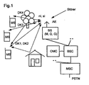
- the radio communication system shown in FIG 1 corresponds in its structure a well-known GSM cellular network, which consists of a multitude of mobile switching centers MSC, who are networked with each other or have access to establish a fixed network PSTN. Furthermore, these are mobile switching centers MSC with at least one base station controller each Connected to BSC. Any base station controller BSC in turn enables a connection to at least a base station BS.
- a base station BS is one Radio station that has a radio connection via a radio interface to build mobile stations MS.
- FIG. 1 shows three radio connections for transmission as an example of useful information ni and signaling information si between three mobile stations MS and a base station BS shown, one mobile station MS two Data channels DK1 and DK2 and the other mobile stations MS one data channel DK3 or DK4 is assigned.
- An operation and maintenance center OMC realizes control and Maintenance functions for the cellular network or for parts thereof.
- the functionality of this structure is provided by the radio communication system used according to the invention; however it is also transferable to other radio communication systems, in which the invention can be used.
- the base station BS is connected to an antenna device, e.g. consists of three individual emitters.
- An antenna device e.g. consists of three individual emitters.
- everyone who Single radiator shines in a sector of the the base station BS supplied radio cell.
- a larger number of individual steel workers according to adaptive antennas are used, so that a spatial Subscriber separation using an SDMA procedure (Space Multiple Access Division) can be used.
- SDMA procedure Space Multiple Access Division
- the base station BS provides the mobile stations MS with organizational information over the lounge area (LA location area) and via the radio cell (radio cell identifier).
- the organizational information is simultaneously radiated over all individual steel of the antenna device.
- connections with the useful information ni and signaling information si between the base station BS and the Mobile stations MS are subject to multipath propagation, which by reflections on buildings in addition to direct path of propagation.
- Antenna device AE results in comparison to the omnidirectional De-radiation a bigger antenna gain.
- the quality of the connections is due to the directional radiation improved.
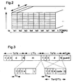
- the frame structure of the radio interface is shown in FIG 2.
- everyone Time slot ts within the frequency range B forms one Frequency channel.
- Within the frequency channels used for user data transmission information is provided by several Transfer connections in radio blocks.
- FDMA (Frequency Division Multiple Access) components are the Radio communication system assigned several frequency ranges B.
- these radio blocks exist for the transmission of user data from data parts with data symbols d, in which sections are embedded with known midambles m on the reception side.
- the data d are connection-specific with a fine structure, a Speizcode, spread, so that on the receiving end, for example K data channels DK1, DK2, DK3, .. DKK through this CDMA components are separable. Any of these data channels DK1, DK2, DK3 Energy E assigned.
- the spread of individual symbols of the data d with Q chips causes within the symbol duration Ts Q subsections of the Duration Tc are transmitted.
- the Q chips form the individual spreading code.
- the middle arm m consists of L Chips, also of duration Tc. Furthermore, within the Time slot ts a guard time guard of duration Tg Compensation for different signal propagation times of the connections successive time slots ts are provided.
- a broadband frequency range B Within a broadband frequency range B the successive time slots ts according to a frame structure divided. Eight time slots ts thus become one frame summarized, with a certain time slot of Frame forms a frequency channel for user data transmission and used repeatedly by a group of connections becomes.
- Other frequency channels e.g. for frequency or Time synchronization of the mobile stations MS will not in every frame, but at a predetermined time introduced within a multi-frame. The distances between these frequency channels determine the capacity that the Radio communication system provides for it.
- the parameters of the radio interface are, for example, as follows: Duration of a radio block 577 ⁇ s Number of chips per midamble m 243 Protection period Tg 32 ⁇ s Data symbols per data part N 33 Symbol duration Ts 6.46 ⁇ s Chips per Q symbol 14 Chip duration Tc 6/13 ⁇ s
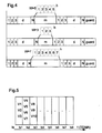
- FIG. 4 An influence on the data rate is shown in FIG. 4. in this connection a constant radio block structure is not assumed, but a change in the radio block structure caused by the control device SE.
- the length of the midamble m is adjusted accordingly of certain traffic conditions on the radio interface carried out.
- the control device SE possibly according to the specifications of other network components: e.g. the base station controller BSC) parameters related to traffic conditions certainly.
- the number M of traffic conditions per time slot is influenced directly the number of estimable channel impulse responses.
- the transmission quality Q is determined by the bit error rate represents and provides information about the quality of the Channel estimation. Is the previous length W of the estimated Channel impulse response h is not sufficient, this leads to deteriorated data detection. By appropriate Change in the ratio of the lengths of midamble m and Data part can be counteracted.
- Connections with similar traffic conditions become one common time slot ts assigned and the optimal midambell length for this time slot for all connections together set.
- the time dependence takes one into account dynamic adaptation of the radio block structure, so that Structure of the radio block the traffic conditions without large Adjusted delay. If the midambell length becomes dynamic Number M of connections in the time slot and to length W adapted to the channel impulse response to be estimated, so increased the spectral efficiency of the radio interface.
- FIG. 5 shows a frame of the TDMA structure of the radio interface. Allocation of connections V1 to V10 to individual Time slots ts1, ts 2, ts 3 are carried out on the network side. It should be taken into account that ts only a limited number of channel impulse responses h in common is appreciable. This limitation results from the fact that the channel impulse responses contain L chips, the channel impulse responses have W coefficients for accurate channel estimation and M represents the number of connections per time slot. The number of jointly estimable channel pulse types h is limited by the inequality L ⁇ M * W + W - 1.
- the allocation strategy therefore provides that in every time slot ts transmit approximately the same number of connections becomes.
- the midambell length is in takes into account each time slot ts, so that, for example, in Time slot ts2, in which the connections V4 to V7 a have longer midamble m, a larger number of connections is transmitted.
- the transmitters and receivers according to FIG. 6 and FIG. 7 relate on radio stations that are both a base station BS or a Mobile station MS can be. However, it only uses signal processing shown for a connection.
- the scrambled data is then in a modulator MOD 4-PSK modulated, converted into 4-PSK symbols and then in spreading means SPR according to individual spreading codes spread.
- This processing is done in a data processing medium DSP in parallel for all data channels DK1, DK2 a connection. It is not shown that in In the case of a base station BS, the other connections as well processed in parallel.
- the data processing medium DSP can by a digital signal processor by a Control device SE is controlled to be performed.
- the spread data of the data channels DK1 and DK2 are superimposed in a summing element S, the data channels DK1 and DK2 being given the same weighting in this superimposition.
- the discrete-time representation of the transmission signal s for the m th subscriber can be carried out according to the following equation:
- K (m) is the number of the data channels of the mth subscriber and N is the number of data symbols d per data part.
- the superimposed subscriber signal is a radio block generator BG fed, taking into account the connection-individual Middle am m puts together the radio block.
- the output signal of a chip pulse filter CIF which connects to the radio block generator BG, is GMSK modulated and has an approximately constant envelope if that Connection uses only one data channel.
- the chip pulse filter CIF performs a convolution with a GMSK main pulse.
- the transmission signal is then transmitted via the antenna device emitted and possibly reached via various Transmission channels the receiving radio station, for example a mobile station MS.
- An individual midamble consisting of L complex chips is used for each connection.
- the necessary M different midambles are derived from a basic midamble code of length M * W, where M is the maximum number of subscribers (connections) and W is the expected maximum number of values of the channel impulse response h.
- the connection-specific Mitambel m is derived by a rotation to the right of the basic Mittelambelcodes by W * m chips and periodic expansion to L ⁇ (M + 1) * W - 1 chips. Since the complex basic midamble code is derived from a binary midamble code by modulation with j q-1 , the transmission signal of the midamble m is also GMSK modulated.
- the data estimation in the joint detection data estimator DE is carried out jointly for all connections.
- A is the system matrix with the CDMA codes c (k) known a priori and the estimated channel impulse responses h (k) .
- the system matrix A has a band structure which is used to reduce the complexity of the algorithm.
- the vector n contains the noise component.
- ZF-BLE Zero Forcing Block Linear Equalizer
- the components have a continuous value and are non-manipulated estimates of the data symbols d.
- H is an upper triangular matrix
- H * T is a lower triangular matrix.
- the data estimate described here is for an individual Data part valid. Furthermore, the Interference between the midamble m and the data parts be taken into account. After separating the data symbols from the Data channels DK1 and DK2 are demodulated in one Demodulator DMO, a descrambling in a deinterleaver DI and channel decoding in convolutional decoder FD instead.
- the digital signal processing is on the transmitting and receiving sides controlled by a control device SE.
- the Control device SE takes into account in particular the number of the data channels DK1, DK2 per connection, the spreading codes of the Data channels DK1, DK2, the current radio block structure and the Channel estimation requirements.
- the superimposition is carried out by the control device SE of the data symbols d in the summing element S is influenced.
- the control device SE In order to can weight the data symbols of different data channels DK1, DK2 can be set. Except for an equal weight data symbols d of a first category (e.g. Signaling information) are weighted higher.
- a first category e.g. Signaling information
- the control device SE also becomes the radio block builder BG controlled and thus the energy per symbol set. The energy per symbol is in the data parts and in the midamble is the same. Under certain traffic conditions can also set a higher weighting of the data parts become.
- the mobile radio network presented in the exemplary embodiments with a combination of FDMA, TDMA and CDMA is for requirements Suitable for 3rd generation systems. In particular it is suitable for implementation in existing GSM mobile radio networks, for which only a small change effort is necessary.
- the design of dual-mode mobile stations MS that both according to the GSM standard as well as the presented TD / CDMA standard work is made easier.
- step variable data rates for example K times 13 kbit / s to set.
Landscapes
- Engineering & Computer Science (AREA)
- Computer Networks & Wireless Communication (AREA)
- Signal Processing (AREA)
- Mobile Radio Communication Systems (AREA)
- Time-Division Multiplex Systems (AREA)
Description
- die Anzahl der Verbindungen im Zeitschlitz, und/oder
- die Übertragungsqualität im Zeitschlitz.
- FIG 1
- ein Blockschaltbild eines Mobilfunknetzes,
- FIG 2
- eine schematische Darstellung der Rahmenstruktur der Funkschnittstelle,
- FIG 3
- eine schematische Darstellung des Aufbaus eines Funkblocks,
- FIG 4
- eine schematische Darstellung von verschiedenen Funkblöcken,
- FIG 5
- eine schematische Darstellung für eine Zuteilungsstrategie von Verbindungen zu Zeitschlitzen,
- FIG 6
- ein Blockschaltbild vom Sender einer Funkstation, und
- FIG 7
- ein Blockschaltbild vom Empfänger einer Funkstation.
| Dauer eines Funkblocks | 577 µs |
| Anzahl Chips pro Mittambel m | 243 |
| Schutzzeit Tg | 32 µs |
| Datensymbole pro Datenteil N | 33 |
| Symboldauer Ts | 6,46 µs |
| Chips pro Symbol Q | 14 |
| Chipdauer Tc | 6 / 13 µs |
- die Anzahl M der Verbindungen im Zeitschlitz, und/oder
- die Übertragungsqualität Q im Zeitschlitz.

Claims (6)
- Verfahren zur Datenübertragung über eine Funkschnittstelle in einem Funk-Kommunikationssystem,
bei demdie Funkschnittstelle in Zeitschlitze (ts) zur Übertragung von Funkblöcken untergliedert ist,in einem Zeitschlitz (ts) Datenkanäle (DK1, DK2, DK3) durch einen individuellen Spreizkode unterscheidbar sind,in einem Zeitschlitz ein endlicher Funkblock bestehend aus Datensymbolen (d) und zumindest einer Mittambel (m) mit bekannten Symbolen übertragen wird, undin dem Zeitschlitz (ts) eine Mittambel (m) als gemeinsame Mittambel (m) zur Kanalschätzung für mehrere Datenkanäle (DK1, DK2, DK3) einer Verbindung übertragen wird, unddas Verhältnis der Länge von Mittambel (m) und einem Datenteil mit Datensymbolen (d) abhängig von der Anzahl Verbindungen in dem Zeitschlitz (ts) und/oder einer bestimmten Übertragungsqualität (Q) eingestellt wird. - Verfahren nach einem der vorherigen Ansprüche, bei dem die Einstellung des Verhältnises der Länge von Mittambel (m) und dem Datenteil mit Datensymbolen (d) zeitabhängig durchgeführt wird.
- Verfahren nach einem der vorherigen Ansprüche, bei dem die Einstellung des Verhältnises der Länge von Mittambel (m) und dem Datenteil mit Datensymbolen (d) zeitschlitzindividuell durchgeführt wird.
- Verfahren nach einem der vorherigen Ansprüche, bei dem die in einem Zeitschlitz (ts) verwendeten Mittambeln (m) von einem gemeinsamen Mittambelgrundcode (mg) abgeleitet werden.
- Verfahren nach einem der vorherigen Ansprüche, bei dem die Datenkanäle (DK1, DK2, DK3) mit unterschiedlichen Mittambellängen unterschiedliche Datenraten aufweisen.
- Funkstation (BTS) zur Datenübertragung in einem Funk-Kommunikationssystem über eine Funkschnittstelle,mit einem Signalverarbeitungsmittel (DSP), das endliche Funkblöcke bestehend aus Datensymbolen (d) und zumindest einer Mittambel (m) mit bekannten Symbolen erzeugt,wobei die Funkschnittstelle in Zeitschlitze (ts) zur Übertragung von Funkblöcken untergliedert ist,ein Steuermittel (SE) ausgestaltet istwobei die Funkblöcke in einem Zeitschlitz (ts) übertragen werden und in einem Zeitschlitz (ts) Datenkanäle (DK1, DK2, DK3) durch einen individuellen Spreizkode unterscheidbar sind, undwobei die Mittambel (m) als gemeinsame Mittambel (m) zur Kanalschätzung für mehrere Datenkanäle (DK1, DK2, DK3) einer Verbindung in dem Zeitschlitz (ts) gesendet wird, und wobeizum Einstellen des Verhältnisses der Länge von Mittambel (m) und einem Datenteil mit Datensymbolen (d) abhängig von einer Anzahl der Verbindungen in dem Zeitschlitz (ts) und/oder einer bestimmten Übertragungsqualität (Q).
Applications Claiming Priority (3)
| Application Number | Priority Date | Filing Date | Title |
|---|---|---|---|
| DE19733336 | 1997-08-01 | ||
| DE19733336A DE19733336A1 (de) | 1997-08-01 | 1997-08-01 | Verfahren und Funkstation zur Datenübertragung |
| PCT/DE1998/002029 WO1999007085A2 (de) | 1997-08-01 | 1998-07-20 | Verfahren und funkstation zur datenübertragung |
Publications (2)
| Publication Number | Publication Date |
|---|---|
| EP1000472A2 EP1000472A2 (de) | 2000-05-17 |
| EP1000472B1 true EP1000472B1 (de) | 2003-09-17 |
Family
ID=7837716
Family Applications (1)
| Application Number | Title | Priority Date | Filing Date |
|---|---|---|---|
| EP98947312A Expired - Lifetime EP1000472B1 (de) | 1997-08-01 | 1998-07-20 | Verfahren und funkstation zur datenübertragung |
Country Status (11)
| Country | Link |
|---|---|
| US (1) | US6606314B1 (de) |
| EP (1) | EP1000472B1 (de) |
| JP (1) | JP3419757B2 (de) |
| KR (1) | KR100362052B1 (de) |
| CN (1) | CN1139203C (de) |
| AU (1) | AU737991B2 (de) |
| BR (1) | BR9811810A (de) |
| CA (1) | CA2298709C (de) |
| DE (2) | DE19733336A1 (de) |
| ES (1) | ES2209208T3 (de) |
| WO (1) | WO1999007085A2 (de) |
Families Citing this family (34)
| Publication number | Priority date | Publication date | Assignee | Title |
|---|---|---|---|---|
| DE19733336A1 (de) | 1997-08-01 | 1999-02-18 | Siemens Ag | Verfahren und Funkstation zur Datenübertragung |
| DE59804936D1 (de) | 1997-10-17 | 2002-08-29 | Siemens Ag | Verfahren und funk-kommunikationssystem zur zuweisung eines frequenzkanals an eine funkstation |
| DE19746083C1 (de) | 1997-10-17 | 1999-03-25 | Siemens Ag | Verfahren und Funkstation zur Datenübertragung |
| BR9911693B1 (pt) * | 1998-06-30 | 2012-12-25 | dispositivo para adaptaÇço de taxas de transmissço em sistemas de telecomunicaÇÕes entre aparelhos transceptores màveis e/ou fixos. | |
| EP1826938A1 (de) * | 1998-07-24 | 2007-08-29 | Matsushita Electric Industrial Co., Ltd. | CDMA-Funkkommunikationssystem und -verfahren |
| DE19911712A1 (de) * | 1999-03-16 | 2000-10-05 | Siemens Ag | Übertragungsverfahren mit variabler Datenrate in einem RACH-Kanal eines Funk-Kommunikationssystems |
| DE19917334A1 (de) * | 1999-04-16 | 2000-10-26 | Siemens Ag | Mittambelstruktur für TD-CDMA-Mobilfunksysteme |
| DE19919361C1 (de) * | 1999-04-28 | 2000-11-23 | Siemens Ag | Verfahren und Funk-Kommunikationssystem zur Datenübertragung |
| GB9910449D0 (en) * | 1999-05-07 | 1999-07-07 | Koninkl Philips Electronics Nv | Radio communication system |
| DE19929252A1 (de) * | 1999-06-25 | 2001-01-11 | Siemens Ag | Verringerung der Wahrscheinlichkeit einer Störung einer empfangsseitigen Kanalschätzung in einem Funkkommunikationssystem |
| US6765894B1 (en) * | 1999-07-05 | 2004-07-20 | Matsushita Electric Industrial Co, Ltd. | Communication terminal apparatus and base station apparatus |
| JP2001024556A (ja) * | 1999-07-05 | 2001-01-26 | Matsushita Electric Ind Co Ltd | 通信装置 |
| US7372825B1 (en) * | 1999-07-13 | 2008-05-13 | Texas Instruments Incorporated | Wireless communications system with cycling of unique cell bit sequences in station communications |
| DE19936318B4 (de) * | 1999-08-02 | 2007-01-11 | Siemens Ag | Verfahren zur Signalübertragung in einem Kanal zum willkürlichen Zugriff eines Funk-Kommunikationssystems sowie Teilnehmerstation |
| DK1252723T3 (da) * | 2000-02-04 | 2004-12-06 | Interdigital Tech Corp | Understöttelse af flerbrugerdetektion i downlinken |
| JP2001251236A (ja) * | 2000-03-06 | 2001-09-14 | Matsushita Electric Ind Co Ltd | 通信装置 |
| ATE266284T1 (de) * | 2000-03-20 | 2004-05-15 | Mitsubishi Electric Inf Tech | Verfahren zur übertragung eines wortes zur anzeigung der übertragungsparametern die den mobilen stationen, in kommunication mit einer basisstation, jeweilend zugeteilt sind |
| GB2360676B (en) * | 2000-03-24 | 2003-12-24 | Roke Manor Research | Improvements in or relating to mobile telecommunications systems |
| EP1143638B1 (de) | 2000-04-04 | 2004-03-24 | Mitsubishi Electric Information Technology Centre Europe B.V. | Verfahren zur Übertragung einer Nachricht zur Anzeigung der Anzahl der Spreizkoden die den mobilen Stationen, in Kommunication mit einer Basisstation, zugeteilt sind |
| DE10056258B4 (de) * | 2000-11-14 | 2004-02-26 | Rohde & Schwarz Gmbh & Co. Kg | Verfahren zur Bestimmung und zur Anzeige der Leistungsanteile der Codes eines CDMA-Signals |
| ATE276633T1 (de) * | 2000-11-28 | 2004-10-15 | Interdigital Tech Corp | Inhaltszugriffsteuersystem und -verfahren |
| US20020110108A1 (en) * | 2000-12-07 | 2002-08-15 | Younglok Kim | Simple block space time transmit diversity using multiple spreading codes |
| DE10147139A1 (de) * | 2001-09-25 | 2003-04-24 | Siemens Ag | Verfahren und Funk-Kommunikationssystem zur Synchronisation von Teilnehmerstationen |
| DE10204622B4 (de) * | 2002-02-05 | 2004-02-05 | Siemens Ag | Verfahren zur Aufrechterhaltung einer Verbindung zwischen einer Basisstation und Teilnehmern eines Funkkommunikationssystems |
| DE10213872A1 (de) * | 2002-03-27 | 2003-10-16 | Siemens Ag | Verfahren zur verbesserten Datenübertragung in einem Übertragungssystem mit kombinierten Übertragungsformaten sowie zugehöriger Rahmenaufbau |
| JP4414342B2 (ja) * | 2002-11-20 | 2010-02-10 | テレフオンアクチーボラゲット エル エム エリクソン(パブル) | チャネル推定を用いたdcオフセット補償のための方法及び装置 |
| CN100486144C (zh) | 2003-04-15 | 2009-05-06 | 大唐移动通信设备有限公司 | 多时隙cdma无线通信系统中提高传输速率的方法 |
| US7437135B2 (en) | 2003-10-30 | 2008-10-14 | Interdigital Technology Corporation | Joint channel equalizer interference canceller advanced receiver |
| US7400692B2 (en) | 2004-01-14 | 2008-07-15 | Interdigital Technology Corporation | Telescoping window based equalization |
| KR100663525B1 (ko) * | 2004-06-10 | 2007-02-28 | 삼성전자주식회사 | 공간-시간 빔 형성을 위한 간섭전력 측정 장치 및 방법 |
| US20070076791A1 (en) * | 2005-07-26 | 2007-04-05 | Interdigital Technology Corporation | Approximate cholesky decomposition-based block linear equalizer |
| KR101351022B1 (ko) | 2007-03-05 | 2014-01-13 | 엘지전자 주식회사 | 방송 신호 송수신 방법 및 방송 신호 수신 장치 |
| US7664143B2 (en) * | 2007-05-01 | 2010-02-16 | Harris Corporation | Communications system using adaptive baseband injected pilot carrier symbols and related method |
| US10396959B2 (en) | 2016-11-10 | 2019-08-27 | Qualcomm Incorporated | Signaling beamforming relationships between control and data channels |
Citations (1)
| Publication number | Priority date | Publication date | Assignee | Title |
|---|---|---|---|---|
| WO1999007084A2 (de) * | 1997-07-31 | 1999-02-11 | Siemens Aktiengesellschaft | Verfahren und funkstation zur datenübertragung |
Family Cites Families (12)
| Publication number | Priority date | Publication date | Assignee | Title |
|---|---|---|---|---|
| US3639909A (en) * | 1970-01-26 | 1972-02-01 | Burroughs Corp | Multichannel input/output control with automatic channel selection |
| US5142534A (en) * | 1990-10-17 | 1992-08-25 | O'neill Communications, Inc. | Wireless integrated voice-data communication system |
| US5283811A (en) * | 1991-09-03 | 1994-02-01 | General Electric Company | Decision feedback equalization for digital cellular radio |
| FI108975B (fi) * | 1993-03-09 | 2002-04-30 | Nokia Corp | Opetusjakso digitaalisessa solukkopuhelinjärjestelmässä |
| US5428608A (en) * | 1993-12-30 | 1995-06-27 | At&T Corp. | Call connection technique |
| FI102797B1 (fi) * | 1994-10-07 | 1999-02-15 | Nokia Telecommunications Oy | Signaalin ilmaisumenetelmä TDMA-matkaviestinjärjestelmän vastaanottimessa sekä menetelmän toteuttava vastaanotin |
| GB2296627B (en) * | 1994-12-23 | 1999-04-14 | Nokia Mobile Phones Ltd | Apparatus and method for data transmission |
| US5592514A (en) * | 1995-03-08 | 1997-01-07 | Lucent Technologies Inc. | Method of performing signal reconstruction at the receiving end of a communications system, such as for GSM |
| JPH08340318A (ja) * | 1995-06-13 | 1996-12-24 | Kokusai Electric Co Ltd | データ伝送方法及び装置 |
| EP0767543A3 (de) | 1995-10-06 | 2000-07-26 | Siemens Aktiengesellschaft | Kodemultiplexnachrichtenübertragung mit Interferenzunterdrückung |
| DE19549148A1 (de) | 1995-12-29 | 1997-07-03 | Siemens Ag | Verfahren und Anordnung zur Funkübertragung von digitalen Signalen |
| DE19733336A1 (de) | 1997-08-01 | 1999-02-18 | Siemens Ag | Verfahren und Funkstation zur Datenübertragung |
-
1997
- 1997-08-01 DE DE19733336A patent/DE19733336A1/de not_active Ceased
-
1998
- 1998-07-20 KR KR1020007001105A patent/KR100362052B1/ko not_active Expired - Fee Related
- 1998-07-20 EP EP98947312A patent/EP1000472B1/de not_active Expired - Lifetime
- 1998-07-20 WO PCT/DE1998/002029 patent/WO1999007085A2/de not_active Ceased
- 1998-07-20 AU AU94303/98A patent/AU737991B2/en not_active Ceased
- 1998-07-20 DE DE59809659T patent/DE59809659D1/de not_active Expired - Lifetime
- 1998-07-20 ES ES98947312T patent/ES2209208T3/es not_active Expired - Lifetime
- 1998-07-20 CA CA002298709A patent/CA2298709C/en not_active Expired - Fee Related
- 1998-07-20 JP JP2000505696A patent/JP3419757B2/ja not_active Expired - Fee Related
- 1998-07-20 BR BR9811810-2A patent/BR9811810A/pt not_active Application Discontinuation
- 1998-07-20 CN CNB988098415A patent/CN1139203C/zh not_active Expired - Fee Related
-
2000
- 2000-02-01 US US09/495,794 patent/US6606314B1/en not_active Expired - Lifetime
Patent Citations (1)
| Publication number | Priority date | Publication date | Assignee | Title |
|---|---|---|---|---|
| WO1999007084A2 (de) * | 1997-07-31 | 1999-02-11 | Siemens Aktiengesellschaft | Verfahren und funkstation zur datenübertragung |
Also Published As
| Publication number | Publication date |
|---|---|
| KR20010022517A (ko) | 2001-03-15 |
| KR100362052B1 (ko) | 2002-11-22 |
| WO1999007085A2 (de) | 1999-02-11 |
| ES2209208T3 (es) | 2004-06-16 |
| DE59809659D1 (de) | 2003-10-23 |
| AU737991B2 (en) | 2001-09-06 |
| JP3419757B2 (ja) | 2003-06-23 |
| JP2001512917A (ja) | 2001-08-28 |
| WO1999007085A3 (de) | 1999-04-29 |
| EP1000472A2 (de) | 2000-05-17 |
| AU9430398A (en) | 1999-02-22 |
| DE19733336A1 (de) | 1999-02-18 |
| CN1139203C (zh) | 2004-02-18 |
| CA2298709C (en) | 2004-09-28 |
| BR9811810A (pt) | 2000-08-15 |
| CN1273719A (zh) | 2000-11-15 |
| CA2298709A1 (en) | 1999-02-11 |
| US6606314B1 (en) | 2003-08-12 |
Similar Documents
| Publication | Publication Date | Title |
|---|---|---|
| EP1000472B1 (de) | Verfahren und funkstation zur datenübertragung | |
| EP1000476B1 (de) | Verfahren und funkstation zur datenübertragung | |
| DE69932929T2 (de) | Verzögerungsnachführung mit Suchfenster in einem Kodemultiplexvielfachzugriffsübertragungssystem | |
| EP0895683B1 (de) | System zur funkübertragung digitaler signale zwischen mehreren teilnehmerstationen und einer basisstation | |
| DE19747367C2 (de) | Verfahren und Anordnung zur Übertragung von Daten über eine Funkschnittstelle in einem Funk-Kommunikationssystem | |
| EP1027783B1 (de) | Verfahren und anordnung zur übertragung von daten über eine funkschnittstelle in einem funk-kommunikationssystem | |
| DE19746083C1 (de) | Verfahren und Funkstation zur Datenübertragung | |
| EP1058974B1 (de) | Verfahren und funk-kommunikationssystem zur informationsübertragung zwischen einer basisstation und weiteren funkstationen | |
| EP1004172B1 (de) | Verfahren und einrichtung zur kanalschätzung | |
| DE19820761C1 (de) | Verfahren und Einrichtung zur Kanalschätzung | |
| EP1031195B1 (de) | Verfahren, empfangseinrichtung und mobilstation zur datenübertragung in einem funk-kommunkationssystem | |
| EP1133834B1 (de) | Verfahren zum steuern von speicherzugriffen bei "rake"-empfängern mit "early-late tracking" in telekommunikationssystemen | |
| DE60314933T2 (de) | Breitbandübertragung mit Frequenzanpassung abhängig von der Kanalschätzung | |
| DE19826036C2 (de) | Verfahren zur Trennung von mehreren überlagerten codierten Nutzersignalen | |
| WO1999020011A1 (de) | Verfahren und funkstation zur datenübertragung | |
| EP1013128B1 (de) | Verfahren und anordnung zur übertragung von nutzdaten in einem funkkommunikationssystem | |
| WO1999060707A2 (de) | Verfahren und basisstation zur signalübertragung in einem organisationskanal eines funk-kommunikationssystems | |
| DE19820684A1 (de) | Verfahren, Mobilstation und Basisstation zum Verbindungsaufbau für eine Mobilstation eines Funk-Kommunikationssystems | |
| EP1027777B1 (de) | Verfahren zur übertragung von informationen über eine funkschnittstelle | |
| EP1125370A1 (de) | Rake-empfänger in mobilfunksystemen der dritten generation | |
| DE19938747A1 (de) | Verfahren zur Kanalschätzung in einem Funk-Kommunikationssystem | |
| WO1998027677A2 (de) | Verfahren und anordnung zur drahtlosen übertragung von daten | |
| DE19810813A1 (de) | Verfahren und Funk-Kommunikationssystem zur Datenübertragung | |
| EP1011232A2 (de) | Verfahren zur Kanalschätzung |
Legal Events
| Date | Code | Title | Description |
|---|---|---|---|
| PUAI | Public reference made under article 153(3) epc to a published international application that has entered the european phase |
Free format text: ORIGINAL CODE: 0009012 |
|
| 17P | Request for examination filed |
Effective date: 20000121 |
|
| AK | Designated contracting states |
Kind code of ref document: A2 Designated state(s): DE ES FR GB IT |
|
| 17Q | First examination report despatched |
Effective date: 20020617 |
|
| GRAH | Despatch of communication of intention to grant a patent |
Free format text: ORIGINAL CODE: EPIDOS IGRA |
|
| GRAH | Despatch of communication of intention to grant a patent |
Free format text: ORIGINAL CODE: EPIDOS IGRA |
|
| GRAA | (expected) grant |
Free format text: ORIGINAL CODE: 0009210 |
|
| AK | Designated contracting states |
Kind code of ref document: B1 Designated state(s): DE ES FR GB IT |
|
| PG25 | Lapsed in a contracting state [announced via postgrant information from national office to epo] |
Ref country code: IT Free format text: LAPSE BECAUSE OF FAILURE TO SUBMIT A TRANSLATION OF THE DESCRIPTION OR TO PAY THE FEE WITHIN THE PRE;WARNING: LAPSES OF ITALIAN PATENTS WITH EFFECTIVE DATE BEFORE 2007 MAY HAVE OCCURRED AT ANY TIME BEFORE 2007. THE CORRECT EFFECTIVE DATE MAY BE DIFFERENT FROM THE ONE RECORDED.SCRIBED TIME-LIMIT Effective date: 20030917 |
|
| REG | Reference to a national code |
Ref country code: GB Ref legal event code: FG4D Free format text: NOT ENGLISH |
|
| REF | Corresponds to: |
Ref document number: 59809659 Country of ref document: DE Date of ref document: 20031023 Kind code of ref document: P |
|
| GBT | Gb: translation of ep patent filed (gb section 77(6)(a)/1977) |
Effective date: 20031219 |
|
| REG | Reference to a national code |
Ref country code: ES Ref legal event code: FG2A Ref document number: 2209208 Country of ref document: ES Kind code of ref document: T3 |
|
| ET | Fr: translation filed | ||
| PLBE | No opposition filed within time limit |
Free format text: ORIGINAL CODE: 0009261 |
|
| STAA | Information on the status of an ep patent application or granted ep patent |
Free format text: STATUS: NO OPPOSITION FILED WITHIN TIME LIMIT |
|
| 26N | No opposition filed |
Effective date: 20040618 |
|
| REG | Reference to a national code |
Ref country code: FR Ref legal event code: PLFP Year of fee payment: 18 |
|
| PGFP | Annual fee paid to national office [announced via postgrant information from national office to epo] |
Ref country code: GB Payment date: 20150709 Year of fee payment: 18 Ref country code: ES Payment date: 20150807 Year of fee payment: 18 Ref country code: DE Payment date: 20150918 Year of fee payment: 18 |
|
| PGFP | Annual fee paid to national office [announced via postgrant information from national office to epo] |
Ref country code: FR Payment date: 20150715 Year of fee payment: 18 |
|
| REG | Reference to a national code |
Ref country code: DE Ref legal event code: R119 Ref document number: 59809659 Country of ref document: DE |
|
| GBPC | Gb: european patent ceased through non-payment of renewal fee |
Effective date: 20160720 |
|
| PG25 | Lapsed in a contracting state [announced via postgrant information from national office to epo] |
Ref country code: FR Free format text: LAPSE BECAUSE OF NON-PAYMENT OF DUE FEES Effective date: 20160801 Ref country code: DE Free format text: LAPSE BECAUSE OF NON-PAYMENT OF DUE FEES Effective date: 20170201 |
|
| REG | Reference to a national code |
Ref country code: FR Ref legal event code: ST Effective date: 20170331 |
|
| PG25 | Lapsed in a contracting state [announced via postgrant information from national office to epo] |
Ref country code: GB Free format text: LAPSE BECAUSE OF NON-PAYMENT OF DUE FEES Effective date: 20160720 |
|
| PG25 | Lapsed in a contracting state [announced via postgrant information from national office to epo] |
Ref country code: ES Free format text: LAPSE BECAUSE OF NON-PAYMENT OF DUE FEES Effective date: 20160721 |
|
| REG | Reference to a national code |
Ref country code: ES Ref legal event code: FD2A Effective date: 20181119 |