EP1000472B1 - Method and radio station for transmitting data - Google Patents
Method and radio station for transmitting data Download PDFInfo
- Publication number
- EP1000472B1 EP1000472B1 EP98947312A EP98947312A EP1000472B1 EP 1000472 B1 EP1000472 B1 EP 1000472B1 EP 98947312 A EP98947312 A EP 98947312A EP 98947312 A EP98947312 A EP 98947312A EP 1000472 B1 EP1000472 B1 EP 1000472B1
- Authority
- EP
- European Patent Office
- Prior art keywords
- data
- midamble
- time slot
- radio
- symbols
- Prior art date
- Legal status (The legal status is an assumption and is not a legal conclusion. Google has not performed a legal analysis and makes no representation as to the accuracy of the status listed.)
- Expired - Lifetime
Links
Images

Classifications
-
- H—ELECTRICITY
- H04—ELECTRIC COMMUNICATION TECHNIQUE
- H04B—TRANSMISSION
- H04B7/00—Radio transmission systems, i.e. using radiation field
- H04B7/24—Radio transmission systems, i.e. using radiation field for communication between two or more posts
- H04B7/26—Radio transmission systems, i.e. using radiation field for communication between two or more posts at least one of which is mobile
-
- H—ELECTRICITY
- H04—ELECTRIC COMMUNICATION TECHNIQUE
- H04B—TRANSMISSION
- H04B1/00—Details of transmission systems, not covered by a single one of groups H04B3/00 - H04B13/00; Details of transmission systems not characterised by the medium used for transmission
- H04B1/69—Spread spectrum techniques
- H04B1/707—Spread spectrum techniques using direct sequence modulation
-
- H—ELECTRICITY
- H04—ELECTRIC COMMUNICATION TECHNIQUE
- H04B—TRANSMISSION
- H04B7/00—Radio transmission systems, i.e. using radiation field
- H04B7/24—Radio transmission systems, i.e. using radiation field for communication between two or more posts
- H04B7/26—Radio transmission systems, i.e. using radiation field for communication between two or more posts at least one of which is mobile
- H04B7/2618—Radio transmission systems, i.e. using radiation field for communication between two or more posts at least one of which is mobile using hybrid code-time division multiple access [CDMA-TDMA]
-
- H—ELECTRICITY
- H04—ELECTRIC COMMUNICATION TECHNIQUE
- H04B—TRANSMISSION
- H04B7/00—Radio transmission systems, i.e. using radiation field
- H04B7/24—Radio transmission systems, i.e. using radiation field for communication between two or more posts
- H04B7/26—Radio transmission systems, i.e. using radiation field for communication between two or more posts at least one of which is mobile
- H04B7/2643—Radio transmission systems, i.e. using radiation field for communication between two or more posts at least one of which is mobile using time-division multiple access [TDMA]
- H04B7/2656—Radio transmission systems, i.e. using radiation field for communication between two or more posts at least one of which is mobile using time-division multiple access [TDMA] for structure of frame, burst
-
- H—ELECTRICITY
- H04—ELECTRIC COMMUNICATION TECHNIQUE
- H04J—MULTIPLEX COMMUNICATION
- H04J13/00—Code division multiplex systems
-
- H—ELECTRICITY
- H04—ELECTRIC COMMUNICATION TECHNIQUE
- H04L—TRANSMISSION OF DIGITAL INFORMATION, e.g. TELEGRAPHIC COMMUNICATION
- H04L7/00—Arrangements for synchronising receiver with transmitter
- H04L7/04—Speed or phase control by synchronisation signals
- H04L7/041—Speed or phase control by synchronisation signals using special codes as synchronising signal
-
- H—ELECTRICITY
- H04—ELECTRIC COMMUNICATION TECHNIQUE
- H04W—WIRELESS COMMUNICATION NETWORKS
- H04W72/00—Local resource management
- H04W72/50—Allocation or scheduling criteria for wireless resources
- H04W72/54—Allocation or scheduling criteria for wireless resources based on quality criteria
-
- Y—GENERAL TAGGING OF NEW TECHNOLOGICAL DEVELOPMENTS; GENERAL TAGGING OF CROSS-SECTIONAL TECHNOLOGIES SPANNING OVER SEVERAL SECTIONS OF THE IPC; TECHNICAL SUBJECTS COVERED BY FORMER USPC CROSS-REFERENCE ART COLLECTIONS [XRACs] AND DIGESTS
- Y10—TECHNICAL SUBJECTS COVERED BY FORMER USPC
- Y10S—TECHNICAL SUBJECTS COVERED BY FORMER USPC CROSS-REFERENCE ART COLLECTIONS [XRACs] AND DIGESTS
- Y10S370/00—Multiplex communications
- Y10S370/912—Packet communications
- Y10S370/913—Wireless or radio
Description
Die Erfindung betrifft ein Verfahren und eine Funkstation zur Datenübertragung über eine Funkschnittstelle in einem Funk-Kommunikationssystem, insbesondere in einem Mobilfunknetz.The invention relates to a method and a radio station for Data transmission via a radio interface in a radio communication system, especially in a cellular network.
In Funk-Kommunikationssystemen werden Nachrichten (beispielsweise Sprache, Bildinformation oder andere Daten) mit Hilfe von elektromagnetischen Wellen übertragen. Das Abstrahlen der elektromagnetischen Wellen erfolgt dabei mit Trägerfrequenzen, die in dem für das jeweilige System vorgesehenen Frequenzband liegen. Beim GSM (Global System for Mobile Communication) liegen die Trägerfrequenzen im Bereich von 900 MHz. Für zukünftige Funk-Kommunikationssysteme, beispielsweise das UMTS (Universal Mobile Telecommunication System) oder andere Systeme der 3. Generation sind Frequenzen im Frequenzband von ca. 2000 MHz vorgesehen.In radio communication systems, messages (for example Language, image information or other data) with the help transmitted by electromagnetic waves. The blasting of the electromagnetic waves occur with carrier frequencies, those in the frequency band intended for the respective system lie. With GSM (Global System for Mobile Communication) the carrier frequencies are in the range of 900 MHz. For future radio communication systems, for example that UMTS (Universal Mobile Telecommunication System) or others 3rd generation systems are frequencies in the frequency band of approx. 2000 MHz is provided.
Die abgestrahlten elektromagnetischen Wellen werden aufgrund von Verlusten durch Reflektion, Beugung und Abstrahlung infolge der Erdkrümmung und dergleichen gedämpft. Infolgedessen sinkt die Empfangsleistung, die bei der empfangenden Funkstation zur Verfügung steht. Diese Dämpfung ist ortsabhängig und bei sich bewegenden Funkstationen auch zeitabhängig.The emitted electromagnetic waves are due to losses due to reflection, diffraction and radiation as a result dampened the curvature of the earth and the like. Consequently the reception power decreases, that at the receiving radio station is available. This damping depends on the location and also time-dependent for moving radio stations.
Zwischen einer sendenden und einer empfangenden Funkstation besteht eine Funkschnittstelle, über die mit Hilfe der elektromagnetischen Wellen eine Datenübertragung stattfindet. Aus DE 195 49 148 ist ein Funk-Kommunikationssystem bekannt, das eine CDMA-Teilnehmerseparierung (CDMA Code Division Multiple Access) nutzt, wobei die Funkschnittstelle zusätzlich eine Zeitmultiplex-Teilnehmerseparierung (TDMA Time Division Multiple Access) aufweist. Eine solche Funkschnittstelle ist auch aus Jung, et al, "A joint detection CDMA mobile radio system concept developed within COST 231", IEEE, Proceedings of the vehicular technology conference, Chicago, 25-28.Juli 1995, Bd.1, S.469-473. Empfangsseitig wird ein JD-Verfahren (Joint Detection) angewendet, um unter Kenntnis von Spreizcodes mehrerer Teilnehmer eine verbesserte Detektion der übertragenen Daten vorzunehmen. Dabei ist es bekannt, daß einer Verbindung über die Funkschnittstelle zumindest zwei Datenkanäle zugeteilt werden können, wobei jeder Datenkanal durch einen individuellen Spreizcode unterscheidbar ist.Between a transmitting and a receiving radio station there is a radio interface via which the electromagnetic Waves a data transfer takes place. Out DE 195 49 148 a radio communication system is known, the a CDMA subscriber separation (CDMA Code Division Multiple Access) uses, with the radio interface additionally one Time division multiplex subscriber separation (TDMA Time Division Multiple access). Such is a radio interface also from Jung, et al, "A joint detection CDMA mobile radio system concept developed within COST 231 ", IEEE, Proceedings of the vehicular technology conference, Chicago, July 25-28 1995, Vol.1, pp.469-473. A JD procedure is used at the receiving end (Joint Detection) applied to knowledge of spreading codes multiple participants improved detection to carry out the transmitted data. It is known that a connection via the radio interface at least two Data channels can be allocated, each data channel can be distinguished by an individual spreading code.
Es ist aus dem GSM-Mobilfunknetz bekannt, daß übertragene Daten als Funkblöcke (Burst) innerhalb von Zeitschlitzen übertragen werden, wobei innerhalb eines Funkblockes Mittambeln mit bekannten Symbolen übertragen werden. Diese Mittambeln können im Sinne von Trainingssequenzen zum empfangsseitigen Abstimmen der Funkstation genutzt werden. Die empfangende Funkstation führt anhand der Mittambeln eine Schätzung der Kanalimpulsantworten für verschiedene Ubertragungskanäle durch. Die Länge der Mittambel ist unabhängig von den Verkehrsbedingungen fest definiert. Aus EP 0 615 352 A1 ist eine variabel einstellbare Länge von Mittambeln in einem TDMA-System bekannt, um die Kanalschätzung zu verbessern.It is known from the GSM mobile radio network that transmitted Data as radio blocks (bursts) within time slots are transmitted, within a radio block Mittambambeln with known symbols. This middle tambourine can in the sense of training sequences on the reception side Tuning the radio station can be used. The receiving one Radio station leads a based on the midamble Estimation of the channel impulse responses for different transmission channels by. The length of the midamble is independent of the traffic conditions firmly defined. From EP 0 615 352 A1 is a variably adjustable length of midambles in one TDMA system known to improve channel estimation.
Für solche Funk-Kommunikationssysteme stellt die Anzahl der gemeinsam schätzbaren Kanalimpulsantworten einen kapazitätsbegrenzenden Faktor dar. Da die Anzahl der Symbole der Mittambel endlich ist und eine Kanalimpulsantwort nicht unendlich kurz sein kann, ist die Zahl der gemeinsam schätzbaren Kanalimpulsantworten begrenzt und somit auch die Anzahl der gemeinsam über die Funkschnittstelle übertragenen Datenkanäle.For such radio communication systems, the number of jointly estimable channel impulse responses a capacity limiting Factor. Since the number of symbols of the midamble finite and a channel impulse response is not infinite can be short is the number of channel impulse responses that can be estimated together limited and therefore also the number of together Data channels transmitted via the radio interface.
Der Erfindung liegt folglich die Aufgabe zugrunde, ein Verfahren
und eine Funkstation zur Datenübertragung über eine
Funkschnittstelle anzugeben, die die funktechnischen Ressourcen
der Funkschnittstelle besser ausnutzen. Die internationale Patentanmeldung WO 99/07084 des gleichen Anmelders, die
unter Artikel 54(3) EPÜ fällt, offenbart ein Verfahren und eine Funkstation
welche/s die gleiche Aufgabe löst. Dazu wird eine Mittambel als gemeinsame
Mittambel zur Kanalschätzung für mehrere Datenkanäle einer Verbindung
übertragen, wobei das Verhältnis der Länge von Mittambel und Datenteil den
Geländebedingungen angepasst werden kann. Gemäß der vorliegenden
Erfindung wird diese Aufgabe
durch das Verfahren mit den Merkmalen des Patentanspruchs
1 und die Funkstation mit den Merkmalen des Patentanspruchs
6 gelöst. Vorteilhafte Weiterbildungen der Erfindung
sind den Unteransprüchen zu entnehmen.The invention is therefore based on the object of a method
and a radio station for data transmission via a
Radio interface specify the radio resources
make better use of the radio interface. International application WO 99/07084 by the same applicant, which
falls under Article 54 (3) EPC, discloses a method and a radio station
which solves the same task. For this purpose, a midamble is used as a common
Midamble for channel estimation for several data channels of a connection
transmitted, the ratio of the length of the midamble and data part den
Terrain conditions can be adjusted. According to the present
Invention becomes this object
by the method with the features of the
Erfindungsgemäß ist beim Verfahren zur Datenübertragung in einem Funk-Kommunikationssystem eine Funkschnittstelle in Zeitschlitze zur Übertragung von Funkblöcken untergliedert. Dabei werden in einem Zeitschlitz die Daten in Datenkanälen übertragen, wobei die Datenkanäle durch einen individuellen Spreizkode unterscheidbar sind. Ein endlicher Funkblock bestehend aus Datensymbolen und zumindest einer Mittambel mit bekannten Symbolen dient der Datenübertragung in einem Datenkanal. In einem Zeitschlitz wird eine Mittambel als gemeinsame Mittambel zur Kanalschätzung für mehrere Datenkanäle einer Verbindung übertragen. Es wird das Verhältnis der Länge von Mittambel und einem Datenteil mit Datensymbolen entsprechend der Verkehrsbedingungen eingestellt.According to the invention in the method for data transmission in a radio communication system a radio interface in Time slots for the transmission of radio blocks subdivided. The data is stored in a time slot in data channels transmitted, the data channels through an individual Spreading codes are distinguishable. A finite radio block consisting from data symbols and at least one midamble with known symbols are used for data transmission in a data channel. In a time slot, a midamble becomes the common midamble Transfer channel estimate for several data channels of a connection. It will The relationship the length of the midamble and a data section with data symbols set according to traffic conditions.
Damit kann durch eine Verlängerung der Mittambel die Begrenzung der schätzbaren Kanalimpulsantworten und damit der in einem Zeitschlitz übertragbaren Verbindungen aufgehoben werden. Wird die Mittambel verlängert, so kann eine größere Anzahl von Verbindungen übertragen werden. Andererseits kann bei nur wenigen Verbindungen pro Zeitschlitz die Mittambellänge verkürzt werden, so daß ein größerer Anteil des Zeitschlitzes für die Übertragung der Datensymbole genutzt werden kann. Die Einstellbarkeit der Mittambellänge gilt auch für Funkblöcke innerhalb von Datenkanälen eines Verbindungstyps (Nutzinformationen, Signalisierungsinformationen, Organisationsinformationen, Zugriffsfunkblöcke).This can limit the limitation by extending the midamble the estimable channel impulse responses and thus the in connections that are transmittable in a time slot. If the midamble is extended, a larger number can be used of connections are transmitted. On the other hand, can with only a few connections per time slot, the midambell length be shortened so that a larger proportion of the time slot be used for the transmission of the data symbols can. The adjustability of the midambell length also applies to Radio blocks within data channels of a connection type (Useful information, signaling information, organizational information, Access radio blocks).
Erfindungsgemäß ist ein Parameter für die Verkehrsbedingungen:
- die Anzahl der Verbindungen im Zeitschlitz, und/oder
- die Übertragungsqualität im Zeitschlitz.
- the number of connections in the time slot, and / or
- the transmission quality in the time slot.
Die Anzahl der Verbindungen pro Zeitschlitz, die momentane Anzahl und/oder die gewünschte Anzahl, berücksichtigt die Anzahl schätzbarer Kanalimpulsantworten. The number of connections per time slot, the current one Number and / or the desired number the number of estimable channel impulse responses.
Die Übertragungsqualität, beispielsweise die Bitfehlerrate o.ä., kann als Parameter zur Einschätzung der Qualität der Kanalschätzung benutzt werden. Ist die bisherige Länge der geschätzen Kanalimpulsantwort nicht ausreichend, so führt dies zu einer verschlechterten Datendetektion. Durch entsprechende Veränderung des Verhältnisses der Längen von Mittambel und Datenteil kann dem entgegengewirkt werden.The transmission quality, for example the bit error rate or similar, can be used as a parameter to assess the quality of the Channel estimation can be used. Is the previous length of the estimated channel impulse response is insufficient, so leads this leads to deteriorated data detection. By appropriate Change in the ratio of lengths of Midamble and data section can be counteracted.
Wird die Mittambellänge dynamisch der Anzahl der Verbindungen im Zeitschlitz und an die Länge der zu schätzenden Kanalimpulsantwort angepaßt, so erhöht sich im Mittel die spektrale Effizienz der Funkschnittstelle.The midamble length becomes dynamic the number of connections in the time slot and to the length of the channel impulse response to be estimated adjusted, the spectral increases on average Radio interface efficiency.
Nach einer weiteren vorteilhaften Ausprägung der Erfindung wird die Einstellung des Verhältnisses der Länge von Mittambel und dem Datenteil mit Datensymbolen zeitabhängig durchgeführt. Dies bedeutet, daß ausgehend von den aktuellen und/oder gewünschten Verkehrsbedingungen der Funkschnittstelle eine Anpassung der Mittambellänge stattfindet. Damit wird die Struktur des Funkblocks den Verkehrsbedingungen ohne große Verzögerung angepaßt. Diese Steuerung kann durch eine Basisstation oder durch andere Netzkomponenten durchgeführt werden.According to a further advantageous embodiment of the invention becomes the setting of the ratio of the length of midamble and the data part with data symbols is time-dependent. This means that starting from the current and / or desired traffic conditions of the radio interface the mid-amber length is adjusted. In order to the structure of the radio block is without traffic conditions adjusted large delay. This control can be done by a Base station or carried out by other network components become.
Die Einstellung des Verhältnises der Länge von Mittambel und dem Datenteil mit Datensymbolen wird alternativ oder zusätzlich zeitschlitzindividuell durchgeführt. Die Verkehrsbedingungen schwanken von Zeitschlitz zu Zeitschlitz. The setting of the ratio of the length of midamble and the data part with data symbols becomes alternative or additional time slot individually carried out. Traffic conditions fluctuate from time slot to time slot.
Es liegt weiterhin im Rahmen der Erfindung, daß die in einem Zeitschlitz verwendeten Mittambeln von einem gemeinsamen Mittambelgrundcode abgeleitet werden. Damit lassen sich sende- und empfangsseitig die Mittambel besonders leicht erzeugen und eine Kanal Schätzung kann für alle Verbindungen, deren Mittambel von einem gemeinsamen Mittambelgrundcode abgeleitet wurden, gemeinsam durchgeführt werden.It is also within the scope of the invention that the in one Middle slot used by a common time slot Mittambelgrundcode are derived. This means that and generate the midamble particularly easily on the receiving side and a channel estimate can be used for all connections, whose midamble is from a common midamble basic code were derived to be carried out together.
Es liegt ebenso im Rahmen der Erfindung, daß die Datenkanäle mit unterschiedlichen Mittambellängen unterschiedliche Datenraten aufweisen. Die unterschiedlichen Datenraten können daher entstehen, daß der Anteil der Datensymbole pro Zeitschlitz sich verändert. Dann kann beispielsweise durch ein Umschalten auf einen sogenannten Halfrate-Betrieb die Sprachübertragung mit gleichbleibender Qualität fortgesetzt werden.It is also within the scope of the invention that the data channels with different midambell lengths have different data rates. The different Data rates can therefore arise from that of data symbols per time slot changes. Then can, for example, by switching to a so-called Half-rate operation with constant voice transmission Quality to be continued.
Ausführungsbeispiele der Erfindung werden anhand der beiliegenden Zeichnungen näher erläutert.Embodiments of the invention are illustrated in the accompanying Drawings explained in more detail.
Dabei zeigen
- FIG 1
- ein Blockschaltbild eines Mobilfunknetzes,
- FIG 2
- eine schematische Darstellung der Rahmenstruktur der Funkschnittstelle,
- FIG 3
- eine schematische Darstellung des Aufbaus eines Funkblocks,
- FIG 4
- eine schematische Darstellung von verschiedenen Funkblöcken,
- FIG 5
- eine schematische Darstellung für eine Zuteilungsstrategie von Verbindungen zu Zeitschlitzen,
- FIG 6
- ein Blockschaltbild vom Sender einer Funkstation, und
- FIG 7
- ein Blockschaltbild vom Empfänger einer Funkstation.
- FIG. 1
- a block diagram of a mobile radio network,
- FIG 2
- 1 shows a schematic representation of the frame structure of the radio interface,
- FIG 3
- 1 shows a schematic representation of the structure of a radio block,
- FIG 4
- a schematic representation of different radio blocks,
- FIG 5
- 1 shows a schematic illustration for an allocation strategy of connections to time slots,
- FIG 6
- a block diagram of the transmitter of a radio station, and
- FIG 7
- a block diagram of the receiver of a radio station.
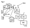
Das in FIG 1 dargestellte Funk-Kommunikationssystem entspricht in seiner Struktur einem bekannten GSM-Mobilfunknetz, das aus einer Vielzahl von Mobilvermittlungsstellen MSC besteht, die untereinander vernetzt sind bzw. den Zugang zu einem Festnetz PSTN herstellen. Weiterhin sind diese Mobilvermittlungsstellen MSC mit jeweils zumindest einem Basisstationscontroller BSC verbunden. Jeder Basisstationscontroller BSC ermöglicht wiederum eine Verbindung zu zumindest einer Basisstation BS. Eine solche Basisstation BS ist eine Funkstation, die über eine Funkschnittstelle eine Funkverbindung zu Mobilstationen MS aufbauen kann.The radio communication system shown in FIG 1 corresponds in its structure a well-known GSM cellular network, which consists of a multitude of mobile switching centers MSC, who are networked with each other or have access to establish a fixed network PSTN. Furthermore, these are mobile switching centers MSC with at least one base station controller each Connected to BSC. Any base station controller BSC in turn enables a connection to at least a base station BS. Such a base station BS is one Radio station that has a radio connection via a radio interface to build mobile stations MS.
In FIG 1 sind beispielhaft drei Funkverbindungen zur Übertragung von Nutzinformationen ni und Signalisierungsinformationen si zwischen drei Mobilstationen MS und einer Basisstation BS dargestellt, wobei einer Mobilstation MS zwei Datenkanäle DK1 und DK2 und den anderen Mobilstationen MS jeweils ein Datenkanal DK3 bzw. DK4 zugeteilt sind. Ein Operations- und Wartungszentrum OMC realisiert Kontroll- und Wartungsfunktionen für das Mobilfunknetz bzw. für Teile davon. Die Funktionalität dieser Struktur wird vom Funk-Kommunmikationssystem nach der Erfindung genutzt; sie ist jedoch auch auf andere Funk-Kommunikationssysteme übertragbar, in denen die Erfindung zum Einsatz kommen kann.1 shows three radio connections for transmission as an example of useful information ni and signaling information si between three mobile stations MS and a base station BS shown, one mobile station MS two Data channels DK1 and DK2 and the other mobile stations MS one data channel DK3 or DK4 is assigned. An operation and maintenance center OMC realizes control and Maintenance functions for the cellular network or for parts thereof. The functionality of this structure is provided by the radio communication system used according to the invention; however it is also transferable to other radio communication systems, in which the invention can be used.
Die Basisstation BS ist mit einer Antenneneinrichtung verbunden, die z.B. aus drei Einzelstrahlern besteht. Jeder der Einzelstrahler strahlt gerichtet in einen Sektor der durch die Basisstation BS versorgten Funkzelle. Es können jedoch alternativ auch eine größere Anzahl von Einzelstahlern (gemäß adaptiver Antennen) eingesetzt werden, so daß auch eine räumliche Teilnehmerseparierung nach einem SDMA-Verfahren (Space Division Multiple Access) eingesetzt werden kann.The base station BS is connected to an antenna device, e.g. consists of three individual emitters. Everyone who Single radiator shines in a sector of the the base station BS supplied radio cell. However, it can alternatively, a larger number of individual steel workers (according to adaptive antennas) are used, so that a spatial Subscriber separation using an SDMA procedure (Space Multiple Access Division) can be used.
Die Basisstation BS stellt den Mobilstationen MS Organisationsinformationen über den Aufenthaltsbereich (LA location area) und über die Funkzelle (Funkzellenkennzeichen) zur Verfügung. Die Organisationsinformationen werden gleichzeitig über alle Einzelstahler der Antenneneinrichtung abgestrahlt.The base station BS provides the mobile stations MS with organizational information over the lounge area (LA location area) and via the radio cell (radio cell identifier). The organizational information is simultaneously radiated over all individual steel of the antenna device.
Die Verbindungen mit den Nutzinformationen ni und Signalisierungsinformationen si zwischen der Basisstation BS und den Mobilstationen MS unterliegen einer Mehrwegeausbreitung, die durch Reflektionen beispielsweise an Gebäuden zusätzlich zum direkten Ausbreitungsweg hervorgerufen werden. Durch eine gerichtete Abstahlung durch bestimmte Einzelstrahler der Antenneneinrichtung AE ergibt sich im Vergleich zur omnidirektionalen Abstahlung ein größerer Antennengewinn. Die Qualität der Verbindungen wird durch die gerichtete Abstrahlung verbessert.The connections with the useful information ni and signaling information si between the base station BS and the Mobile stations MS are subject to multipath propagation, which by reflections on buildings in addition to direct path of propagation. By a directed radiation by certain single emitters Antenna device AE results in comparison to the omnidirectional De-radiation a bigger antenna gain. The The quality of the connections is due to the directional radiation improved.
Geht man von einer Bewegung der Mobilstationen MS aus, dann führt die Mehrwegeausbreitung zusammen mit weiteren Störungen dazu, daß bei der empfangenden Mobilstation MS sich die Signalkomponenten der verschiedenen Ausbreitungswege eines Teilnehmersignals zeitabhängig überlagern. Weiterhin wird davon ausgegangen, daß sich die Teilnehmersignale verschiedener Basisstationen BS am Empfangsort zu einem Empfangssignal rx in einem Frequenzkanal überlagern. Aufgabe einer empfangenden Mobilstation MS ist es, in den Teilnehmersignalen übertragene Daten d der Nutzinformationen ni, Signalisierungsinformationen si und Daten der Organisationsinformationen zu detektieren.If one assumes a movement of the mobile stations MS, then leads to multipath propagation along with other disturbances to the fact that the signal components at the receiving mobile station MS the different propagation paths of a subscriber signal overlay over time. It will continue assumed that the subscriber signals differ Base stations BS at the receiving location for a received signal rx overlay in a frequency channel. Task of a receiving Mobile station MS is transmitted in the subscriber signals Data d of the useful information ni, signaling information si and data of the organizational information to be detected.
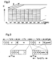
Die Rahmenstruktur der Funkschnittstelle ist aus FIG 2 ersichtlich. Gemäß einer TDMA-Komponente ist eine Aufteilung eines breitbandigen Frequenzbereiches, beispielsweise der Bandbreite B = 1,6 MHz, in mehrere Zeitschlitze ts, beispielsweise 8 Zeitschlitze ts1 bis ts8 vorgesehen. Jeder Zeitschlitz ts innerhalb des Frequenzbereiches B bildet einen Frequenzkanal. Innerhalb der Frequenzkanäle, die zur Nutzdatenübertragung vorgesehen sind, werden Informationen mehrerer Verbindungen in Funkblöcken übertragen. Gemäß einer FDMA (Frequency Division Multiple Access)-Komponente sind dem Funk-Kommunikationssystem mehrere Frequenzbereiche B zugeordnet.The frame structure of the radio interface is shown in FIG 2. According to a TDMA component, there is a split a broadband frequency range, for example the Bandwidth B = 1.6 MHz, in several time slots ts, for example 8 time slots ts1 to ts8 are provided. Everyone Time slot ts within the frequency range B forms one Frequency channel. Within the frequency channels used for user data transmission information is provided by several Transfer connections in radio blocks. According to an FDMA (Frequency Division Multiple Access) components are the Radio communication system assigned several frequency ranges B.
Gemäß FIG 3 bestehen diese Funkblöcke zur Nutzdatenübertragung aus Datenteilen mit Datensymbolen d, in denen Abschnitte mit empfangsseitig bekannten Mittambeln m eingebettet sind. Die Daten d sind verbindungsindividuell mit einer Feinstruktur, einem Speizcode, gespreizt, so daß empfangsseitig beispielsweise K Datenkanäle DK1, DK2, DK3,.. DKK durch diese CDMA-Komponente separierbar sind. Jeden dieser Datenkanäle DK1, DK2, DK3,.. DKK wird sendeseitig pro Symbol eine bestimmte Energie E zugeordnet.According to FIG 3, these radio blocks exist for the transmission of user data from data parts with data symbols d, in which sections are embedded with known midambles m on the reception side. The data d are connection-specific with a fine structure, a Speizcode, spread, so that on the receiving end, for example K data channels DK1, DK2, DK3, .. DKK through this CDMA components are separable. Any of these data channels DK1, DK2, DK3 Energy E assigned.
Die Spreizung von einzelnen Symbolen der Daten d mit Q Chips bewirkt, daß innerhalb der Symboldauer Ts Q Subabschnitte der Dauer Tc übertragen werden. Die Q Chips bilden dabei den individuellen Spreizkode. Die Mittambel m besteht aus L Chips, ebenfalls der Dauer Tc. Weiterhin ist innerhalb des Zeitschlitzes ts eine Schutzzeit guard der Dauer Tg zur Kompensation unterschiedlicher Signalaufzeiten der Verbindungen aufeinanderfolgender Zeitschlitze ts vorgesehen. The spread of individual symbols of the data d with Q chips causes within the symbol duration Ts Q subsections of the Duration Tc are transmitted. The Q chips form the individual spreading code. The middle arm m consists of L Chips, also of duration Tc. Furthermore, within the Time slot ts a guard time guard of duration Tg Compensation for different signal propagation times of the connections successive time slots ts are provided.
Innerhalb eines breitbandigen Frequenzbereiches B werden die aufeinanderfolgenden Zeitschlitze ts nach einer Rahmenstruktur gegliedert. So werden acht Zeitschlitze ts zu einem Rahmen zusammengefaßt, wobei ein bestimmter Zeitschlitz des Rahmens einen Frequenzkanal zur Nutzdatenübertragung bildet und wiederkehrend von einer Gruppe von Verbindungen genutzt wird. Weitere Frequenzkanäle, beispielsweise zur Frequenzoder Zeitsynchronisation der Mobilstationen MS werden nicht in jedem Rahmen, jedoch zu einem vorgegebenen Zeitpunkten innerhalb eines Multirahmens eingeführt. Die Abstände zwischen diesen Frequenzkanälen bestimmen die Kapazität, die das Funk-Kommunikationssystem dafür zur Verfügung stellt.Within a broadband frequency range B the successive time slots ts according to a frame structure divided. Eight time slots ts thus become one frame summarized, with a certain time slot of Frame forms a frequency channel for user data transmission and used repeatedly by a group of connections becomes. Other frequency channels, e.g. for frequency or Time synchronization of the mobile stations MS will not in every frame, but at a predetermined time introduced within a multi-frame. The distances between these frequency channels determine the capacity that the Radio communication system provides for it.
Die Parameter der Funkschnittstelle sind z.B. wie folgt:
In Aufwärts- (MS -> BS) und Abwärtsrichtung (BS -> MS) können die Parameter auch unterschiedlich eingestellt werden.In upward (MS -> BS) and downward direction (BS -> MS) can the parameters can also be set differently.
Eine Beeinflussung der Datenrate ist in FIG 4 gezeigt. Hierbei wird nicht von einer konstanten Funkblockstruktur ausgegangen, sondern eine Veränderung der Funkblockstruktur wird durch die Steuereinrichtung SE veranlaßt. An influence on the data rate is shown in FIG. 4. in this connection a constant radio block structure is not assumed, but a change in the radio block structure caused by the control device SE.
Die Einstellung der Länge der Mittambel m wird entsprechend von bestimmten Verkehrsbedingungen auf der Funkschnittstelle durchgeführt. So werden durch die Steuereinrichtung SE (ggf. nach Vorgaben anderer Netzkomponenten: z.B. dem Basisstationscontroller BSC) Parameter zu den Verkehrsbedingungen bestimmt.The length of the midamble m is adjusted accordingly of certain traffic conditions on the radio interface carried out. Thus, the control device SE (possibly according to the specifications of other network components: e.g. the base station controller BSC) parameters related to traffic conditions certainly.
Diese Parameter für die Verkehrsbedingungen:
- die Anzahl M der Verbindungen im Zeitschlitz, und/oder
- die Übertragungsqualität Q im Zeitschlitz.
- the number M of connections in the time slot, and / or
- the transmission quality Q in the time slot.
Diese Parameter können sowohl aktuell gemessene Werte oder zukünftige Werte sein, wobei letztere entstehen würden, falls weitere Verbindungen bzw. Datenkanäle einem Zeitschlitz ts zugewiesen werden.These parameters can be both currently measured values or future values, the latter would arise if further connections or data channels a time slot ts be assigned to.
Die Anzahl M der Verkehrsbedingungen pro Zeitschlitz beeinflußt direkt die Anzahl schätzbarer Kanalimpulsantworten. The number M of traffic conditions per time slot is influenced directly the number of estimable channel impulse responses.
Die Übertragungsqualität Q, wird durch die Bitfehlerrate repräsentiert und gibt Aufschluß über die Qualität der Kanalschätzung. Ist die bisherige Länge W der geschätzen Kanalimpulsantwort h nicht ausreichend, so führt dies zu einer verschlechterten Datendetektion. Durch entsprechende Veränderung des Verhältnisses der Längen von Mittambel m und Datenteil kann dem entgegengewirkt werden.The transmission quality Q is determined by the bit error rate represents and provides information about the quality of the Channel estimation. Is the previous length W of the estimated Channel impulse response h is not sufficient, this leads to deteriorated data detection. By appropriate Change in the ratio of the lengths of midamble m and Data part can be counteracted.
Schwanken die Verkehrsbedingungen in einer Funkzelle stark, so ist die Einstellung zusätzlich zeitschlitz- bzw. zeitabhängig.Traffic conditions fluctuate strong in a radio cell, that's the attitude additionally time slot or time dependent.
Verbindungen mit ähnlichen Verkehrsbedingungen werden einem gemeinsamen Zeitschlitz ts zugeordnet und die optimale Mittambellänge für diesen Zeitschlitz für alle Verbindungen gemeinsam eingestellt. Die Zeitabhängigkeit berücksichtigt eine dynamische Anpassung der Funkblockstruktur, damit wird die Struktur des Funkblocks den Verkehrsbedingungen ohne große Verzögerung angepaßt. Wird die Mittambellänge dynamisch der Anzahl M der Verbindungen im Zeitschlitz und an die Länge W der zu schätzenden Kanalimpulsantwort angepaßt, so erhöht sich im Mittel die spektrale Effizienz der Funkschnittstelle.Connections with similar traffic conditions become one common time slot ts assigned and the optimal midambell length for this time slot for all connections together set. The time dependence takes one into account dynamic adaptation of the radio block structure, so that Structure of the radio block the traffic conditions without large Adjusted delay. If the midambell length becomes dynamic Number M of connections in the time slot and to length W adapted to the channel impulse response to be estimated, so increased the spectral efficiency of the radio interface.
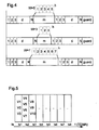
FIG 5 zeigt einen Rahmen der TDMA-Struktur der Funkschnittstelle.
Die Zuteilung der Verbindungen V1 bis V10 zu einzelnen
Zeitschlitzen ts1, ts 2, ts 3 wird netzseitig durchgeführt.
Dabei ist zu berücksichtigen, daß pro Zeitschlitz ts
nur eine begrenzte Anzahl von Kanalimpulsantworten h gemeinsam
schätzbar ist. Diese Limitierung ergibt sich daraus, daß
die Kanalimpulsantworten L Chips enthalten, die Kanalimpulsantworten
zur genauen Kanalschätzung W Koeffizienten aufweisen
und M die Anzahl der Verbindungen pro Zeitschlitz darstellt.
Die Anzahl gemeinsam schätzbarer Kanalimpulsarten h
ist dabei durch die Ungleichung L ≥ M * W + W - 1 begrenzt.5 shows a frame of the TDMA structure of the radio interface.
Allocation of connections V1 to V10 to individual
Time slots ts1,
Die Zuteilungsstrategie sieht daher vor, daß in jedem Zeitschitz ts in etwa eine gleiche Anzahl von Verbindungen übertragen wird. In zweiter Hinsicht wird die Mittambellänge in jedem Zeitschlitz ts berücksichtigt, so daß beispielsweise im Zeitschlitz ts2, bei dem die Verbindungen V4 bis V7 eine längere Mittambel m haben, eine größere Anzahl von Verbindungen übertragen wird.The allocation strategy therefore provides that in every time slot ts transmit approximately the same number of connections becomes. Secondly, the midambell length is in takes into account each time slot ts, so that, for example, in Time slot ts2, in which the connections V4 to V7 a have longer midamble m, a larger number of connections is transmitted.
Durch die Nutzung einer gemeinsamen Mittambel m für mehrere Datenkanäle DK1 und DK2 ist es möglich in einem Zeitschlitz ts eine größere Anzahl von Datenkanälen DK1 und DK2 zu übertragen. Dies führt zu einer Erhöhung der Datenrate pro Zeitschlitz ts oder zu einer Verlängerung der schätzbaren Kanalimpulsantworten h (für komplizierte Geländestrukturen) in diesem Zeitschlitz ts.By using a common midamble for several Data channels DK1 and DK2 are possible in one time slot ts to transmit a larger number of data channels DK1 and DK2. This leads to an increase in the data rate per time slot ts or to extend the estimable channel impulse responses h (for complicated terrain structures) in this time slot ts.
Die Sende- bzw. Empfänger nach FIG 6 bzw. FIG 7 beziehen sich auf Funkstationen, die sowohl eine Basisstation BS oder eine Mobilstation MS sein können. Es wird jedoch nur die Signalverarbeitung für eine Verbindung gezeigt.The transmitters and receivers according to FIG. 6 and FIG. 7 relate on radio stations that are both a base station BS or a Mobile station MS can be. However, it only uses signal processing shown for a connection.
Der Sender nach FIG 6 nimmt die zuvor digitalisierten Datensymbole
d einer Datenquelle (Mikrofon oder netzseitige Verbindung)
auf, wobei die beiden Datenteile mit je N=33 Datensymbolen
d getrennt verarbeitet werden. Es findet zuerst eine
Kanalcodierung der Rate 1/2 und constraint length 5 im Faltungscodierer
FC statt, worauf sich eine Verwürfelung im
Interleaver I mit einer Verwürfelungstiefe von 4 oder 16
anschließt.6 takes the previously digitized data symbols
d a data source (microphone or network connection)
on, with the two data parts each with N = 33 data symbols
d processed separately. It finds one
Die verwürfelten Daten werden anschließend in einem Modulator MOD 4-PSK moduliert, in 4-PSK Symbole umgewandelt und daraufhin in Spreizmitteln SPR entsprechend individueller Spreizcodes gespreizt. Diese Verarbeitung wird in einem Datenverarbeitungsmittel DSP parallel für alle Datenkanäle DK1, DK2 einer Verbindung durchgeführt. Nicht dargestellt ist, daß im Fall einer Basisstation BS die übrigen Verbindungen ebenfalls parallel verarbeitet werden. Das Datenverarbeitungsmittel DSP kann durch einen digitalen Signalprozessor, der durch eine Steuereinrichtung SE gesteuert wird, durchgeführt werden.The scrambled data is then in a modulator MOD 4-PSK modulated, converted into 4-PSK symbols and then in spreading means SPR according to individual spreading codes spread. This processing is done in a data processing medium DSP in parallel for all data channels DK1, DK2 a connection. It is not shown that in In the case of a base station BS, the other connections as well processed in parallel. The data processing medium DSP can by a digital signal processor by a Control device SE is controlled to be performed.
In einem Summierglied S werden die gespreizten Daten der Datenkanäle
DK1 und DK2 überlagert, wobei bei dieser Überlagerung
die Datenkanäle DK1 und DK2 eine gleiche Wichtung
erfahren. Die zeitdiskrete Darstellung des Sendesignals s für
den m-ten Teilnehmer kann nach folgender Gleichung erfolgen:

Wobei K(m) die Nummer der Datenkanäle des m-ten Teilnehmers und N die Anzahl der Datensymbole d pro Datenteil ist. Das überlagerte Teilnehmersignal wird einem Funkblockbildner BG zugeführt, der unter der Berücksichtigung der verbindungsindivuellen Mittambel m den Funkblock zusammenstellt.Where K (m) is the number of the data channels of the mth subscriber and N is the number of data symbols d per data part. The superimposed subscriber signal is a radio block generator BG fed, taking into account the connection-individual Middle am m puts together the radio block.
Da komplexe CDMA-Codes verwendet werden, die von binären CDMA-Codes durch eine Multiplikation mit jq-1 abgeleitet werden, ist das Ausgangssignal eines Chipimpulsfilters CIF, das sich an den Funkblockbildner BG anschließt GMSK moduliert und hat eine in etwa konstante Einhüllende falls die Verbindung nur einen Datenkanal nutzt. Das Chipimpulsfilter CIF führt eine Faltung mit einem GMSK-Hauptimpuls durch.Since complex CDMA codes are used which are derived from binary CDMA codes by multiplication by j q-1 , the output signal of a chip pulse filter CIF, which connects to the radio block generator BG, is GMSK modulated and has an approximately constant envelope if that Connection uses only one data channel. The chip pulse filter CIF performs a convolution with a GMSK main pulse.
Anschließend an die digitale Signalverarbeitung wird sendeseitig eine Digital/Analog-Wandlung, eine Übertragung ins Sendefrequenzband und eine Verstärkung des Signals durchgeführt. Daraufhin wird das Sendesignal über die Antenneneinrichtung abgestrahlt und erreicht ggf. über verschiedene Übertragungskanäle die empfangende Funkstation, beispielsweise eine Mobilstation MS.Subsequent to the digital signal processing is on the transmission side a digital / analog conversion, a transfer to Transmitted frequency band and an amplification of the signal performed. The transmission signal is then transmitted via the antenna device emitted and possibly reached via various Transmission channels the receiving radio station, for example a mobile station MS.
Pro Verbindung wird dabei eine individuelle Mittambel m bestehend aus L komplexen Chips genutzt. Die notwendigen M unterschiedlichen Mittambeln werden von einem Grundmittambelcode der Länge M * W abgeleitet, wobei M die maximale Anzahl von Teilnehmern (Verbindungen) und W die erwartete maximale Anzahl von Werten der Kanalimpulsantwort h darstellt. Die verbindungsindividuelle Mitambel m wird durch eine Rotation nach rechts des Grundmittambelcodes um W * m Chips und periodischer Dehnung bis L ≥ (M + 1)* W - 1 Chips abgeleitet. Da der komplexe Grundmittambelcode von einem binären Mittambelcode durch Modulation mit jq-1 abgeleitet wird, ist das Sendesignal der Mittambel m ebenfalls GMSK moduliert.An individual midamble consisting of L complex chips is used for each connection. The necessary M different midambles are derived from a basic midamble code of length M * W, where M is the maximum number of subscribers (connections) and W is the expected maximum number of values of the channel impulse response h. The connection-specific Mitambel m is derived by a rotation to the right of the basic Mittelambelcodes by W * m chips and periodic expansion to L ≥ (M + 1) * W - 1 chips. Since the complex basic midamble code is derived from a binary midamble code by modulation with j q-1 , the transmission signal of the midamble m is also GMSK modulated.
Empfangsseitig (siehe FIG 7) findet nach einer analogen Verarbeitung,
d.h. Verstärkung, Filterung, Konvertierung ins
Basisband, eine digitale Tiefpaßfilterung der Empfangssignale
e in einen digitalen Tiefpaßfilter DLF statt. Ein Teil des
Empfangssignals e, der durch einen Vektor em der Länge L = M
* W repräsentiert wird und keine Interferenzen des Datenteils
enthält, wird einem Kanalschätzer KS übermittelt. Die Kanalschätzung
aller M Kanalimpulsantworten h wird gemäß
Die Datenschätzung im Joint Detection Datenschätzer DE wird für alle Verbindungen gemeinsam durchgeführt. Die Spreizcodes werden mit c(k) die Empfangsdaten mit d(k) und die korrespondierenden Kanalimpulsantworten mit h(k) repräsentiert, wobei k = 1 bis K ist. The data estimation in the joint detection data estimator DE is carried out jointly for all connections. The spreading codes are represented by c (k), the received data by d (k) and the corresponding channel impulse responses by h (k) , where k = 1 to K.
Der Teil des Empfangssignals der für die Datenschätzung benutzt
wird, wird durch den Vektor
Für diese Symbolanordnung hat die Systemmatrix A eine
Bandstruktur, die zur Reduzierung der Komplexität des
Algorithmus genutzt wird. Der Vektor n enthält den Rauschanteil.
Die Datenschätzung wird durch einen Zero Forcing
Block Linear Equalizer (ZF-BLE) nach folgender Gleichung
durchgeführt:
Die Komponenten haben ein kontinuierlichen Wert und sind
nicht manipulierte Schätzwerte der Datensymbole d. Um die
Berechnung von d zu vereinfachen, kann das Problem in ein
lineares Gleichungssystem der Form
Die hier beschriebene Datenschätzung ist für einen einzelnen Datenteil gültig. Weiterhin müssen bei der Datenschätzung die Interferenzen zwischen der Mittambel m und den Datenteilen berücksichtigt werden. Nach der Trennung der Datensymbole der Datenkanäle DK1 und DK2 findet eine Demodulation in einem Demodulator DMO, eine Entwürfelung in einem Deinterleaver DI und eine Kanaldecodierung in Faltungsdecodierer FD statt.The data estimate described here is for an individual Data part valid. Furthermore, the Interference between the midamble m and the data parts be taken into account. After separating the data symbols from the Data channels DK1 and DK2 are demodulated in one Demodulator DMO, a descrambling in a deinterleaver DI and channel decoding in convolutional decoder FD instead.
Sendeseitig und empfangsseitig wird die digitale Signalverarbeitung durch eine Steuereinrichtung SE gesteuert. Die Steuereinrichtung SE berücksichtigt insbesondere die Anzahl der Datenkanäle DK1, DK2 pro Verbindung, die Spreizcodes der Datenkanäle DK1, DK2, die aktuelle Funkblockstruktur und die Anforderungen an die Kanalschätzung.The digital signal processing is on the transmitting and receiving sides controlled by a control device SE. The Control device SE takes into account in particular the number of the data channels DK1, DK2 per connection, the spreading codes of the Data channels DK1, DK2, the current radio block structure and the Channel estimation requirements.
Insbesondere wird durch die Steuereinrichtung SE die Überlagerung der Datensymbole d im Summierglied S beeinflußt. Damit kann die Gewichtung der Datensymbole verschiedener Datenkanäle DK1, DK2 eingestellt werden. Außer einer Gleichgewichtung können auch Datensymbole d einer ersten Kategorie (z.B. Signalisierungsinformationen) höher gewichtet werden. Durch die Steuereinrichtung SE wird ebenfall der Funkblockbildner BG gesteuert und somit die Energie pro Symbol eingestellt. Die Energie pro Symbol ist dabei in den Datenteilen und in der Mittambel m gleich. Unter bestimmten Verkehrsbedingungen kann auch eine höhere Gewichtung der Datenteile eingestellt werden.In particular, the superimposition is carried out by the control device SE of the data symbols d in the summing element S is influenced. In order to can weight the data symbols of different data channels DK1, DK2 can be set. Except for an equal weight data symbols d of a first category (e.g. Signaling information) are weighted higher. By the control device SE also becomes the radio block builder BG controlled and thus the energy per symbol set. The energy per symbol is in the data parts and in the midamble is the same. Under certain traffic conditions can also set a higher weighting of the data parts become.
Das in den Ausführungsbeispielen vorgestellte Mobilfunknetz mit einer Kombination von FDMA, TDMA und CDMA ist für Anforderungen an Systeme der 3. Generation geeignet. Insbesondere eignet es sich für eine Implementierung in bestehende GSM-Mobilfunknetze, für die ein nur geringer Änderungsaufwand nötig ist. Der Entwurf von Dual-Mode Mobilstationen MS, die sowohl nach dem GSM-Standard, als auch nach dem vorgestellten TD/CDMA Standard funktionieren, wird erleichtert.The mobile radio network presented in the exemplary embodiments with a combination of FDMA, TDMA and CDMA is for requirements Suitable for 3rd generation systems. In particular it is suitable for implementation in existing GSM mobile radio networks, for which only a small change effort is necessary. The design of dual-mode mobile stations MS that both according to the GSM standard as well as the presented TD / CDMA standard work is made easier.
Durch die Erhöhung der Datenraten pro Zeitschlitz, indem gemeinsame Mittambeln genutzt werden (channel pooling), ist es möglich, schrittweise variable Datenraten von beispielsweise K mal 13 kbit/s einzustellen.By increasing the data rates per time slot by common midambles are used (channel pooling) it is possible to step by step variable data rates for example K times 13 kbit / s to set.
Claims (6)
- Method for data transmission via a radio interface in a radio communications system,
in whichthe radio interface is subdivided into time slots (ts) for transmission of bursts,in one time slot (ts), data channels (DK1, DK2, DK3) can be distinguished by means of an individual spread code,a finite burst comprising data symbols (d) and at least one midamble (m) with known symbols is transmitted in one time slot, andin the time slot (ts), one midamble (m) is transmitted as a common midamble (m) for channel estimation for a plurality of data channels (DK1, DK2, DK3) for a connection, andthe ratio of the length of the midamble (m) and a data part with data symbols (d) is adjusted depending on connections in the time slot (ts) and/or on a certain transmission quality (Q). - Method according to Claim 1, in which
the ratio of the length of the midamble (m) and the data part with data symbols (d) is adjusted as a function of time. - Method according to one of the preceding claims, in which
the ratio of the length of the midamble (m) and the data part with data symbols (d) is adjusted for individual time slots. - Method according to one of the preceding claims, in which
the midambles (m) used in a time slot (ts) are derived from a common midamble basic code (mg). - Method according to one of the preceding claims, in which
the data channels (DK1, DK2, DK3) with different midamble lengths have different data rates. - Radio station (BTS) for data transmission in a radio communications system via a radio interface,having a signal processing means (DSP) which produces finite bursts comprising data symbols (d) and at least one midamble (m) with known symbols,with the radio interface being subdivided into time slots (ts) for transmission of bursts,in which case the bursts are transmitted in a time slot (ts) and, in one time slot (ts), data channels (DK1, DK2, DK3) can be distinguished by means of an individual spread code, andthe midamble (m) is sent as a common midamble (m) for channel estimation for a plurality of data channels (DK1, DK2, DK3) of a connection in the time slot (ts),a control means being designed for adjusting the radio of the length of the midamble (m) and a data part with data symbols (d) depending on the number of the connections in the time slot (ts) and/or on a specific transmission quality (Q).
Applications Claiming Priority (3)
| Application Number | Priority Date | Filing Date | Title |
|---|---|---|---|
| DE19733336A DE19733336A1 (en) | 1997-08-01 | 1997-08-01 | Method and radio station for data transmission |
| DE19733336 | 1997-08-01 | ||
| PCT/DE1998/002029 WO1999007085A2 (en) | 1997-08-01 | 1998-07-20 | Method and radio station for transmitting data |
Publications (2)
| Publication Number | Publication Date |
|---|---|
| EP1000472A2 EP1000472A2 (en) | 2000-05-17 |
| EP1000472B1 true EP1000472B1 (en) | 2003-09-17 |
Family
ID=7837716
Family Applications (1)
| Application Number | Title | Priority Date | Filing Date |
|---|---|---|---|
| EP98947312A Expired - Lifetime EP1000472B1 (en) | 1997-08-01 | 1998-07-20 | Method and radio station for transmitting data |
Country Status (11)
| Country | Link |
|---|---|
| US (1) | US6606314B1 (en) |
| EP (1) | EP1000472B1 (en) |
| JP (1) | JP3419757B2 (en) |
| KR (1) | KR100362052B1 (en) |
| CN (1) | CN1139203C (en) |
| AU (1) | AU737991B2 (en) |
| BR (1) | BR9811810A (en) |
| CA (1) | CA2298709C (en) |
| DE (2) | DE19733336A1 (en) |
| ES (1) | ES2209208T3 (en) |
| WO (1) | WO1999007085A2 (en) |
Families Citing this family (32)
| Publication number | Priority date | Publication date | Assignee | Title |
|---|---|---|---|---|
| DE19733336A1 (en) | 1997-08-01 | 1999-02-18 | Siemens Ag | Method and radio station for data transmission |
| EP1044580B1 (en) | 1997-10-17 | 2002-07-24 | Siemens Aktiengesellschaft | Radiocommunication method and system for assigning a frequency channel to a radio station |
| DE19746083C1 (en) * | 1997-10-17 | 1999-03-25 | Siemens Ag | Data transmission method for radio interface in radio communications system |
| BR9911693B1 (en) * | 1998-06-30 | 2012-12-25 | device for adjusting transmission rates in telecommunications systems between mobile and / or fixed transceiver apparatus. | |
| DE69936019T2 (en) * | 1998-07-24 | 2007-08-30 | Matsushita Electric Industrial Co. Limited, Kadoma | CDMA radio transmission system and method |
| DE19911712A1 (en) * | 1999-03-16 | 2000-10-05 | Siemens Ag | Transmission method with variable data rate in a RACH channel of a radio communication system |
| DE19917334A1 (en) * | 1999-04-16 | 2000-10-26 | Siemens Ag | Channel estimation method for TD-CDMA mobile radio system |
| DE19919361C1 (en) * | 1999-04-28 | 2000-11-23 | Siemens Ag | Method and radio communication system for data transmission |
| GB9910449D0 (en) * | 1999-05-07 | 1999-07-07 | Koninkl Philips Electronics Nv | Radio communication system |
| DE19929252A1 (en) * | 1999-06-25 | 2001-01-11 | Siemens Ag | Reducing the likelihood of interference in a reception-side channel estimate in a radio communication system |
| US6765894B1 (en) * | 1999-07-05 | 2004-07-20 | Matsushita Electric Industrial Co, Ltd. | Communication terminal apparatus and base station apparatus |
| JP2001024556A (en) * | 1999-07-05 | 2001-01-26 | Matsushita Electric Ind Co Ltd | Communication device |
| US7372825B1 (en) * | 1999-07-13 | 2008-05-13 | Texas Instruments Incorporated | Wireless communications system with cycling of unique cell bit sequences in station communications |
| DE19936318B4 (en) * | 1999-08-02 | 2007-01-11 | Siemens Ag | Method for signal transmission in a channel for random access of a radio communication system and subscriber station |
| SG161102A1 (en) * | 2000-02-04 | 2010-05-27 | Interdigital Tech Corp | Support multiuser detection in the downlink |
| JP2001251236A (en) * | 2000-03-06 | 2001-09-14 | Matsushita Electric Ind Co Ltd | Communications equipment |
| DE60040936D1 (en) * | 2000-03-20 | 2009-01-08 | Mitsubishi Electric Inf Tech | A base station for transmitting a word representative of the spreading codes allocated to the mobile stations in communication with the base station, respectively |
| GB2360676B (en) * | 2000-03-24 | 2003-12-24 | Roke Manor Research | Improvements in or relating to mobile telecommunications systems |
| EP1143638B1 (en) | 2000-04-04 | 2004-03-24 | Mitsubishi Electric Information Technology Centre Europe B.V. | Method for transmitting an information representative of the number of spreading codes allocated to the mobile stations in communication with a base station |
| DE10056258B4 (en) * | 2000-11-14 | 2004-02-26 | Rohde & Schwarz Gmbh & Co. Kg | Method for determining and displaying the power components of the codes of a CDMA signal |
| DK1338170T3 (en) * | 2000-11-28 | 2005-01-10 | Interdigital Tech Corp | Conflicting approach management system and approach |
| US20020110108A1 (en) * | 2000-12-07 | 2002-08-15 | Younglok Kim | Simple block space time transmit diversity using multiple spreading codes |
| DE10147139A1 (en) * | 2001-09-25 | 2003-04-24 | Siemens Ag | Quantitative position assessment device for machine parts e.g. shaft, workpiece, has two-dimensionally readable optoelectronic sensor which reflects incident light beam directly to another optoelectronic sensor |
| DE10204622B4 (en) * | 2002-02-05 | 2004-02-05 | Siemens Ag | Method for maintaining a connection between a base station and participants in a radio communication system |
| DE10213872A1 (en) * | 2002-03-27 | 2003-10-16 | Siemens Ag | Method for improved data transmission in a transmission system with combined transmission formats uses frame segments with training sequences and transmission formats. |
| AU2003271714A1 (en) * | 2002-11-20 | 2004-06-15 | Telefonaktiebolaget Lm Ericsson (Publ) | Method and corresponding arrangement for dc offset compensation using channel estimation |
| CN100486144C (en) * | 2003-04-15 | 2009-05-06 | 大唐移动通信设备有限公司 | Method of raising transmission speed in multi-slot CDMA radio communication system |
| KR100663525B1 (en) * | 2004-06-10 | 2007-02-28 | 삼성전자주식회사 | Interference power measurement apparatus and method required space-time beam forming |
| US20070076791A1 (en) * | 2005-07-26 | 2007-04-05 | Interdigital Technology Corporation | Approximate cholesky decomposition-based block linear equalizer |
| KR101351022B1 (en) | 2007-03-05 | 2014-01-13 | 엘지전자 주식회사 | method for transmitting/receiving a broadcast signal and apparatus for receiving a broadcast signal |
| US7664143B2 (en) * | 2007-05-01 | 2010-02-16 | Harris Corporation | Communications system using adaptive baseband injected pilot carrier symbols and related method |
| US10396959B2 (en) | 2016-11-10 | 2019-08-27 | Qualcomm Incorporated | Signaling beamforming relationships between control and data channels |
Citations (1)
| Publication number | Priority date | Publication date | Assignee | Title |
|---|---|---|---|---|
| WO1999007084A2 (en) * | 1997-07-31 | 1999-02-11 | Siemens Aktiengesellschaft | Method and radio station for transmitting data |
Family Cites Families (12)
| Publication number | Priority date | Publication date | Assignee | Title |
|---|---|---|---|---|
| US3639909A (en) * | 1970-01-26 | 1972-02-01 | Burroughs Corp | Multichannel input/output control with automatic channel selection |
| US5142534A (en) * | 1990-10-17 | 1992-08-25 | O'neill Communications, Inc. | Wireless integrated voice-data communication system |
| US5283811A (en) * | 1991-09-03 | 1994-02-01 | General Electric Company | Decision feedback equalization for digital cellular radio |
| FI108975B (en) * | 1993-03-09 | 2002-04-30 | Nokia Corp | Exercise sequence in a digital cellular radio telephone system |
| US5428608A (en) * | 1993-12-30 | 1995-06-27 | At&T Corp. | Call connection technique |
| FI102797B (en) * | 1994-10-07 | 1999-02-15 | Nokia Mobile Phones Ltd | A method of signal detection in a receiver of a TDMA mobile communication system, and a receiver implementing the method |
| GB2296627B (en) * | 1994-12-23 | 1999-04-14 | Nokia Mobile Phones Ltd | Apparatus and method for data transmission |
| US5592514A (en) * | 1995-03-08 | 1997-01-07 | Lucent Technologies Inc. | Method of performing signal reconstruction at the receiving end of a communications system, such as for GSM |
| JPH08340318A (en) * | 1995-06-13 | 1996-12-24 | Kokusai Electric Co Ltd | Method and device for data transmission |
| EP0767543A3 (en) | 1995-10-06 | 2000-07-26 | Siemens Aktiengesellschaft | Code division multiplex communication with interference suppression |
| DE19549148A1 (en) | 1995-12-29 | 1997-07-03 | Siemens Ag | Method and arrangement for radio transmission of digital signals |
| DE19733336A1 (en) | 1997-08-01 | 1999-02-18 | Siemens Ag | Method and radio station for data transmission |
-
1997
- 1997-08-01 DE DE19733336A patent/DE19733336A1/en not_active Ceased
-
1998
- 1998-07-20 KR KR1020007001105A patent/KR100362052B1/en not_active IP Right Cessation
- 1998-07-20 ES ES98947312T patent/ES2209208T3/en not_active Expired - Lifetime
- 1998-07-20 DE DE59809659T patent/DE59809659D1/en not_active Expired - Lifetime
- 1998-07-20 JP JP2000505696A patent/JP3419757B2/en not_active Expired - Fee Related
- 1998-07-20 AU AU94303/98A patent/AU737991B2/en not_active Ceased
- 1998-07-20 WO PCT/DE1998/002029 patent/WO1999007085A2/en active IP Right Grant
- 1998-07-20 CN CNB988098415A patent/CN1139203C/en not_active Expired - Fee Related
- 1998-07-20 BR BR9811810-2A patent/BR9811810A/en not_active Application Discontinuation
- 1998-07-20 EP EP98947312A patent/EP1000472B1/en not_active Expired - Lifetime
- 1998-07-20 CA CA002298709A patent/CA2298709C/en not_active Expired - Fee Related
-
2000
- 2000-02-01 US US09/495,794 patent/US6606314B1/en not_active Expired - Lifetime
Patent Citations (1)
| Publication number | Priority date | Publication date | Assignee | Title |
|---|---|---|---|---|
| WO1999007084A2 (en) * | 1997-07-31 | 1999-02-11 | Siemens Aktiengesellschaft | Method and radio station for transmitting data |
Also Published As
| Publication number | Publication date |
|---|---|
| AU9430398A (en) | 1999-02-22 |
| WO1999007085A2 (en) | 1999-02-11 |
| DE19733336A1 (en) | 1999-02-18 |
| AU737991B2 (en) | 2001-09-06 |
| JP2001512917A (en) | 2001-08-28 |
| US6606314B1 (en) | 2003-08-12 |
| KR20010022517A (en) | 2001-03-15 |
| CA2298709C (en) | 2004-09-28 |
| CN1273719A (en) | 2000-11-15 |
| JP3419757B2 (en) | 2003-06-23 |
| EP1000472A2 (en) | 2000-05-17 |
| ES2209208T3 (en) | 2004-06-16 |
| KR100362052B1 (en) | 2002-11-22 |
| WO1999007085A3 (en) | 1999-04-29 |
| CN1139203C (en) | 2004-02-18 |
| BR9811810A (en) | 2000-08-15 |
| CA2298709A1 (en) | 1999-02-11 |
| DE59809659D1 (en) | 2003-10-23 |
Similar Documents
| Publication | Publication Date | Title |
|---|---|---|
| EP1000472B1 (en) | Method and radio station for transmitting data | |
| EP1000476B1 (en) | Method and radio station for transmitting data | |
| DE69932929T2 (en) | Delay tracking with search window in a code division multiple access transmission system | |
| EP0895683B1 (en) | System for radio transmission of digital signals between a plurality of subscriber stations and a base station | |
| DE19747367C2 (en) | Method and arrangement for the transmission of data via a radio interface in a radio communication system | |
| EP1027783B1 (en) | Methods and arrangement for transmitting data via a radio interface in a radiocommunications system | |
| EP1058974B1 (en) | Method and radiocommunications system for transmitting information between a base station and other stations | |
| DE19746083C1 (en) | Data transmission method for radio interface in radio communications system | |
| EP1004172B1 (en) | Channel estimation method and device | |
| DE19820761C1 (en) | Channel estimation e.g. GSM system | |
| EP1031195B1 (en) | Process, receiver and mobile station used for data transmission in a radio communication system | |
| EP1133834B1 (en) | Method for controlling memory access in rake receivers with early-late tracking in telecommunications systems | |
| DE60314933T2 (en) | Broadband transmission with frequency adaptation depending on the channel estimate | |
| DE19826036C2 (en) | Method for separating several superimposed coded user signals | |
| WO1999020011A1 (en) | Method and radio station for transmitting data | |
| EP1027815A2 (en) | Radiocommunications system and control device | |
| EP1013128B1 (en) | Method and device for transmitting user data in a radiocommunication system | |
| DE19820684A1 (en) | Mobile station connection set=up method for radio communication system | |
| WO1999060707A2 (en) | Method and base station for transmitting signals in a control channel of a radiocommunications system | |
| EP1027777B1 (en) | Method for transmitting information via a radio interface | |
| WO2000025437A1 (en) | Rake receiver in third generation mobile radiotelephone systems | |
| DE19938747A1 (en) | Method for channel estimation in a radio communication system | |
| WO1998027677A2 (en) | Method and arrangement for wireless data transmission | |
| DE19810813A1 (en) | Data transmission method for radio communication system | |
| WO2000070835A1 (en) | Method for blindly estimating channel parameters |
Legal Events
| Date | Code | Title | Description |
|---|---|---|---|
| PUAI | Public reference made under article 153(3) epc to a published international application that has entered the european phase |
Free format text: ORIGINAL CODE: 0009012 |
|
| 17P | Request for examination filed |
Effective date: 20000121 |
|
| AK | Designated contracting states |
Kind code of ref document: A2 Designated state(s): DE ES FR GB IT |
|
| 17Q | First examination report despatched |
Effective date: 20020617 |
|
| GRAH | Despatch of communication of intention to grant a patent |
Free format text: ORIGINAL CODE: EPIDOS IGRA |
|
| GRAH | Despatch of communication of intention to grant a patent |
Free format text: ORIGINAL CODE: EPIDOS IGRA |
|
| GRAA | (expected) grant |
Free format text: ORIGINAL CODE: 0009210 |
|
| AK | Designated contracting states |
Kind code of ref document: B1 Designated state(s): DE ES FR GB IT |
|
| PG25 | Lapsed in a contracting state [announced via postgrant information from national office to epo] |
Ref country code: IT Free format text: LAPSE BECAUSE OF FAILURE TO SUBMIT A TRANSLATION OF THE DESCRIPTION OR TO PAY THE FEE WITHIN THE PRE;WARNING: LAPSES OF ITALIAN PATENTS WITH EFFECTIVE DATE BEFORE 2007 MAY HAVE OCCURRED AT ANY TIME BEFORE 2007. THE CORRECT EFFECTIVE DATE MAY BE DIFFERENT FROM THE ONE RECORDED.SCRIBED TIME-LIMIT Effective date: 20030917 |
|
| REG | Reference to a national code |
Ref country code: GB Ref legal event code: FG4D Free format text: NOT ENGLISH |
|
| REF | Corresponds to: |
Ref document number: 59809659 Country of ref document: DE Date of ref document: 20031023 Kind code of ref document: P |
|
| GBT | Gb: translation of ep patent filed (gb section 77(6)(a)/1977) |
Effective date: 20031219 |
|
| REG | Reference to a national code |
Ref country code: ES Ref legal event code: FG2A Ref document number: 2209208 Country of ref document: ES Kind code of ref document: T3 |
|
| ET | Fr: translation filed | ||
| PLBE | No opposition filed within time limit |
Free format text: ORIGINAL CODE: 0009261 |
|
| STAA | Information on the status of an ep patent application or granted ep patent |
Free format text: STATUS: NO OPPOSITION FILED WITHIN TIME LIMIT |
|
| 26N | No opposition filed |
Effective date: 20040618 |
|
| REG | Reference to a national code |
Ref country code: FR Ref legal event code: PLFP Year of fee payment: 18 |
|
| PGFP | Annual fee paid to national office [announced via postgrant information from national office to epo] |
Ref country code: GB Payment date: 20150709 Year of fee payment: 18 Ref country code: ES Payment date: 20150807 Year of fee payment: 18 Ref country code: DE Payment date: 20150918 Year of fee payment: 18 |
|
| PGFP | Annual fee paid to national office [announced via postgrant information from national office to epo] |
Ref country code: FR Payment date: 20150715 Year of fee payment: 18 |
|
| REG | Reference to a national code |
Ref country code: DE Ref legal event code: R119 Ref document number: 59809659 Country of ref document: DE |
|
| GBPC | Gb: european patent ceased through non-payment of renewal fee |
Effective date: 20160720 |
|
| PG25 | Lapsed in a contracting state [announced via postgrant information from national office to epo] |
Ref country code: FR Free format text: LAPSE BECAUSE OF NON-PAYMENT OF DUE FEES Effective date: 20160801 Ref country code: DE Free format text: LAPSE BECAUSE OF NON-PAYMENT OF DUE FEES Effective date: 20170201 |
|
| REG | Reference to a national code |
Ref country code: FR Ref legal event code: ST Effective date: 20170331 |
|
| PG25 | Lapsed in a contracting state [announced via postgrant information from national office to epo] |
Ref country code: GB Free format text: LAPSE BECAUSE OF NON-PAYMENT OF DUE FEES Effective date: 20160720 |
|
| PG25 | Lapsed in a contracting state [announced via postgrant information from national office to epo] |
Ref country code: ES Free format text: LAPSE BECAUSE OF NON-PAYMENT OF DUE FEES Effective date: 20160721 |
|
| REG | Reference to a national code |
Ref country code: ES Ref legal event code: FD2A Effective date: 20181119 |