EP0996494B1 - Verfahren zur katalytischen reduktion von stickoxiden - Google Patents
Verfahren zur katalytischen reduktion von stickoxiden Download PDFInfo
- Publication number
- EP0996494B1 EP0996494B1 EP98935017A EP98935017A EP0996494B1 EP 0996494 B1 EP0996494 B1 EP 0996494B1 EP 98935017 A EP98935017 A EP 98935017A EP 98935017 A EP98935017 A EP 98935017A EP 0996494 B1 EP0996494 B1 EP 0996494B1
- Authority
- EP
- European Patent Office
- Prior art keywords
- process according
- exhaust gas
- ammonia
- reaction space
- exhaust gases
- Prior art date
- Legal status (The legal status is an assumption and is not a legal conclusion. Google has not performed a legal analysis and makes no representation as to the accuracy of the status listed.)
- Expired - Lifetime
Links
- 238000000034 method Methods 0.000 title claims abstract description 30
- 238000010531 catalytic reduction reaction Methods 0.000 title claims abstract description 11
- 239000003054 catalyst Substances 0.000 claims abstract description 18
- 238000006243 chemical reaction Methods 0.000 claims abstract description 15
- 229910021536 Zeolite Inorganic materials 0.000 claims abstract description 12
- 239000013543 active substance Substances 0.000 claims abstract description 12
- HNPSIPDUKPIQMN-UHFFFAOYSA-N dioxosilane;oxo(oxoalumanyloxy)alumane Chemical compound O=[Si]=O.O=[Al]O[Al]=O HNPSIPDUKPIQMN-UHFFFAOYSA-N 0.000 claims abstract description 12
- 239000010457 zeolite Substances 0.000 claims abstract description 12
- 238000002485 combustion reaction Methods 0.000 claims abstract description 9
- QVGXLLKOCUKJST-UHFFFAOYSA-N atomic oxygen Chemical compound [O] QVGXLLKOCUKJST-UHFFFAOYSA-N 0.000 claims abstract description 8
- 239000001301 oxygen Substances 0.000 claims abstract description 8
- 229910052760 oxygen Inorganic materials 0.000 claims abstract description 8
- 238000005341 cation exchange Methods 0.000 claims abstract description 5
- QGZKDVFQNNGYKY-UHFFFAOYSA-N Ammonia Chemical compound N QGZKDVFQNNGYKY-UHFFFAOYSA-N 0.000 claims description 45
- 239000007789 gas Substances 0.000 claims description 44
- MWUXSHHQAYIFBG-UHFFFAOYSA-N nitrogen oxide Inorganic materials O=[N] MWUXSHHQAYIFBG-UHFFFAOYSA-N 0.000 claims description 42
- 229910021529 ammonia Inorganic materials 0.000 claims description 20
- XEEYBQQBJWHFJM-UHFFFAOYSA-N Iron Chemical compound [Fe] XEEYBQQBJWHFJM-UHFFFAOYSA-N 0.000 claims description 14
- 239000000203 mixture Substances 0.000 claims description 10
- 239000007787 solid Substances 0.000 claims description 8
- 239000002245 particle Substances 0.000 claims description 7
- RYGMFSIKBFXOCR-UHFFFAOYSA-N Copper Chemical compound [Cu] RYGMFSIKBFXOCR-UHFFFAOYSA-N 0.000 claims description 6
- 150000001875 compounds Chemical class 0.000 claims description 6
- 229910052802 copper Inorganic materials 0.000 claims description 6
- 239000010949 copper Substances 0.000 claims description 6
- 229910052742 iron Inorganic materials 0.000 claims description 6
- 229910052680 mordenite Inorganic materials 0.000 claims description 6
- 239000000725 suspension Substances 0.000 claims description 5
- VHUUQVKOLVNVRT-UHFFFAOYSA-N Ammonium hydroxide Chemical compound [NH4+].[OH-] VHUUQVKOLVNVRT-UHFFFAOYSA-N 0.000 claims description 3
- 229920002472 Starch Polymers 0.000 claims description 2
- XSQUKJJJFZCRTK-UHFFFAOYSA-N Urea Chemical compound NC(N)=O XSQUKJJJFZCRTK-UHFFFAOYSA-N 0.000 claims description 2
- 150000001298 alcohols Chemical class 0.000 claims description 2
- JYIBXUUINYLWLR-UHFFFAOYSA-N aluminum;calcium;potassium;silicon;sodium;trihydrate Chemical compound O.O.O.[Na].[Al].[Si].[K].[Ca] JYIBXUUINYLWLR-UHFFFAOYSA-N 0.000 claims description 2
- 239000001913 cellulose Substances 0.000 claims description 2
- 229920002678 cellulose Polymers 0.000 claims description 2
- 229910001603 clinoptilolite Inorganic materials 0.000 claims description 2
- GUJOJGAPFQRJSV-UHFFFAOYSA-N dialuminum;dioxosilane;oxygen(2-);hydrate Chemical compound O.[O-2].[O-2].[O-2].[Al+3].[Al+3].O=[Si]=O.O=[Si]=O.O=[Si]=O.O=[Si]=O GUJOJGAPFQRJSV-UHFFFAOYSA-N 0.000 claims description 2
- 229910021645 metal ion Inorganic materials 0.000 claims description 2
- 229910052901 montmorillonite Inorganic materials 0.000 claims description 2
- ZVCDLGYNFYZZOK-UHFFFAOYSA-M sodium cyanate Chemical compound [Na]OC#N ZVCDLGYNFYZZOK-UHFFFAOYSA-M 0.000 claims description 2
- 239000008107 starch Substances 0.000 claims description 2
- 235000019698 starch Nutrition 0.000 claims description 2
- VTYYLEPIZMXCLO-UHFFFAOYSA-L Calcium carbonate Chemical compound [Ca+2].[O-]C([O-])=O VTYYLEPIZMXCLO-UHFFFAOYSA-L 0.000 claims 2
- ODINCKMPIJJUCX-UHFFFAOYSA-N Calcium oxide Chemical compound [Ca]=O ODINCKMPIJJUCX-UHFFFAOYSA-N 0.000 claims 2
- VYPSYNLAJGMNEJ-UHFFFAOYSA-N Silicium dioxide Chemical compound O=[Si]=O VYPSYNLAJGMNEJ-UHFFFAOYSA-N 0.000 claims 2
- 229910000069 nitrogen hydride Inorganic materials 0.000 claims 2
- RNMCQEMQGJHTQF-UHFFFAOYSA-N 3,5,6,7-tetrahydrotetrazolo[1,5-b][1,2,4]triazine Chemical compound N1CCN=C2N=NNN21 RNMCQEMQGJHTQF-UHFFFAOYSA-N 0.000 claims 1
- 229910000013 Ammonium bicarbonate Inorganic materials 0.000 claims 1
- XZMCDFZZKTWFGF-UHFFFAOYSA-N Cyanamide Chemical compound NC#N XZMCDFZZKTWFGF-UHFFFAOYSA-N 0.000 claims 1
- VZTDIZULWFCMLS-UHFFFAOYSA-N ammonium formate Chemical compound [NH4+].[O-]C=O VZTDIZULWFCMLS-UHFFFAOYSA-N 0.000 claims 1
- 229910000019 calcium carbonate Inorganic materials 0.000 claims 1
- AXCZMVOFGPJBDE-UHFFFAOYSA-L calcium dihydroxide Chemical compound [OH-].[OH-].[Ca+2] AXCZMVOFGPJBDE-UHFFFAOYSA-L 0.000 claims 1
- 239000000920 calcium hydroxide Substances 0.000 claims 1
- 229910001861 calcium hydroxide Inorganic materials 0.000 claims 1
- 239000000292 calcium oxide Substances 0.000 claims 1
- 229910052681 coesite Inorganic materials 0.000 claims 1
- 229910052906 cristobalite Inorganic materials 0.000 claims 1
- XLYOFNOQVPJJNP-ZSJDYOACSA-N heavy water Substances [2H]O[2H] XLYOFNOQVPJJNP-ZSJDYOACSA-N 0.000 claims 1
- 239000000377 silicon dioxide Substances 0.000 claims 1
- 229910052682 stishovite Inorganic materials 0.000 claims 1
- 229910052905 tridymite Inorganic materials 0.000 claims 1
- UGFAIRIUMAVXCW-UHFFFAOYSA-N Carbon monoxide Chemical compound [O+]#[C-] UGFAIRIUMAVXCW-UHFFFAOYSA-N 0.000 abstract 3
- 239000003546 flue gas Substances 0.000 abstract 3
- 229940095054 ammoniac Drugs 0.000 abstract 1
- 150000001455 metallic ions Chemical class 0.000 abstract 1
- 229910018072 Al 2 O 3 Inorganic materials 0.000 description 4
- 229910004298 SiO 2 Inorganic materials 0.000 description 4
- 230000003197 catalytic effect Effects 0.000 description 4
- 239000003638 chemical reducing agent Substances 0.000 description 4
- 235000011114 ammonium hydroxide Nutrition 0.000 description 3
- -1 tungsten ions Chemical class 0.000 description 3
- PXHVJJICTQNCMI-UHFFFAOYSA-N Nickel Chemical compound [Ni] PXHVJJICTQNCMI-UHFFFAOYSA-N 0.000 description 2
- GWEVSGVZZGPLCZ-UHFFFAOYSA-N Titan oxide Chemical compound O=[Ti]=O GWEVSGVZZGPLCZ-UHFFFAOYSA-N 0.000 description 2
- 230000002378 acidificating effect Effects 0.000 description 2
- 230000015556 catabolic process Effects 0.000 description 2
- 239000000428 dust Substances 0.000 description 2
- 238000000926 separation method Methods 0.000 description 2
- 229910052721 tungsten Inorganic materials 0.000 description 2
- 239000010937 tungsten Substances 0.000 description 2
- 229910052720 vanadium Inorganic materials 0.000 description 2
- GPPXJZIENCGNKB-UHFFFAOYSA-N vanadium Chemical compound [V]#[V] GPPXJZIENCGNKB-UHFFFAOYSA-N 0.000 description 2
- 229910052684 Cerium Inorganic materials 0.000 description 1
- VYZAMTAEIAYCRO-UHFFFAOYSA-N Chromium Chemical compound [Cr] VYZAMTAEIAYCRO-UHFFFAOYSA-N 0.000 description 1
- VMQMZMRVKUZKQL-UHFFFAOYSA-N Cu+ Chemical group [Cu+] VMQMZMRVKUZKQL-UHFFFAOYSA-N 0.000 description 1
- ZOKXTWBITQBERF-UHFFFAOYSA-N Molybdenum Chemical compound [Mo] ZOKXTWBITQBERF-UHFFFAOYSA-N 0.000 description 1
- HCHKCACWOHOZIP-UHFFFAOYSA-N Zinc Chemical compound [Zn] HCHKCACWOHOZIP-UHFFFAOYSA-N 0.000 description 1
- 238000005299 abrasion Methods 0.000 description 1
- 239000002253 acid Substances 0.000 description 1
- 239000003513 alkali Substances 0.000 description 1
- 229910001413 alkali metal ion Inorganic materials 0.000 description 1
- 229910001420 alkaline earth metal ion Inorganic materials 0.000 description 1
- 229910000323 aluminium silicate Inorganic materials 0.000 description 1
- 230000015572 biosynthetic process Effects 0.000 description 1
- 239000004202 carbamide Substances 0.000 description 1
- 238000006555 catalytic reaction Methods 0.000 description 1
- 239000000919 ceramic Substances 0.000 description 1
- ZMIGMASIKSOYAM-UHFFFAOYSA-N cerium Chemical compound [Ce][Ce][Ce][Ce][Ce][Ce][Ce][Ce][Ce][Ce][Ce][Ce][Ce][Ce][Ce][Ce][Ce][Ce][Ce][Ce][Ce][Ce][Ce][Ce][Ce][Ce][Ce][Ce][Ce][Ce][Ce][Ce][Ce][Ce][Ce][Ce][Ce][Ce] ZMIGMASIKSOYAM-UHFFFAOYSA-N 0.000 description 1
- 229910052804 chromium Inorganic materials 0.000 description 1
- 239000011651 chromium Substances 0.000 description 1
- 238000004140 cleaning Methods 0.000 description 1
- 239000011248 coating agent Substances 0.000 description 1
- 238000000576 coating method Methods 0.000 description 1
- 229910017052 cobalt Inorganic materials 0.000 description 1
- 239000010941 cobalt Substances 0.000 description 1
- GUTLYIVDDKVIGB-UHFFFAOYSA-N cobalt atom Chemical compound [Co] GUTLYIVDDKVIGB-UHFFFAOYSA-N 0.000 description 1
- 239000000567 combustion gas Substances 0.000 description 1
- 230000007423 decrease Effects 0.000 description 1
- 238000006731 degradation reaction Methods 0.000 description 1
- 230000001627 detrimental effect Effects 0.000 description 1
- 230000007613 environmental effect Effects 0.000 description 1
- 239000003344 environmental pollutant Substances 0.000 description 1
- 239000001257 hydrogen Substances 0.000 description 1
- 229910052739 hydrogen Inorganic materials 0.000 description 1
- 230000001771 impaired effect Effects 0.000 description 1
- WPBNNNQJVZRUHP-UHFFFAOYSA-L manganese(2+);methyl n-[[2-(methoxycarbonylcarbamothioylamino)phenyl]carbamothioyl]carbamate;n-[2-(sulfidocarbothioylamino)ethyl]carbamodithioate Chemical compound [Mn+2].[S-]C(=S)NCCNC([S-])=S.COC(=O)NC(=S)NC1=CC=CC=C1NC(=S)NC(=O)OC WPBNNNQJVZRUHP-UHFFFAOYSA-L 0.000 description 1
- 229910052751 metal Inorganic materials 0.000 description 1
- 239000002184 metal Substances 0.000 description 1
- 150000002739 metals Chemical class 0.000 description 1
- 229910052750 molybdenum Inorganic materials 0.000 description 1
- 239000011733 molybdenum Substances 0.000 description 1
- 229910052759 nickel Inorganic materials 0.000 description 1
- 229910052758 niobium Inorganic materials 0.000 description 1
- 239000010955 niobium Substances 0.000 description 1
- GUCVJGMIXFAOAE-UHFFFAOYSA-N niobium atom Chemical compound [Nb] GUCVJGMIXFAOAE-UHFFFAOYSA-N 0.000 description 1
- 231100000719 pollutant Toxicity 0.000 description 1
- 239000011148 porous material Substances 0.000 description 1
- 238000006722 reduction reaction Methods 0.000 description 1
- 230000000717 retained effect Effects 0.000 description 1
- 239000000126 substance Substances 0.000 description 1
- 239000004408 titanium dioxide Substances 0.000 description 1
- WFKWXMTUELFFGS-UHFFFAOYSA-N tungsten Chemical compound [W] WFKWXMTUELFFGS-UHFFFAOYSA-N 0.000 description 1
- 238000005406 washing Methods 0.000 description 1
- 229910052725 zinc Inorganic materials 0.000 description 1
- 239000011701 zinc Substances 0.000 description 1
Images

Classifications
-
- B—PERFORMING OPERATIONS; TRANSPORTING
- B01—PHYSICAL OR CHEMICAL PROCESSES OR APPARATUS IN GENERAL
- B01D—SEPARATION
- B01D53/00—Separation of gases or vapours; Recovering vapours of volatile solvents from gases; Chemical or biological purification of waste gases, e.g. engine exhaust gases, smoke, fumes, flue gases, aerosols
- B01D53/34—Chemical or biological purification of waste gases
- B01D53/74—General processes for purification of waste gases; Apparatus or devices specially adapted therefor
- B01D53/86—Catalytic processes
- B01D53/8621—Removing nitrogen compounds
- B01D53/8625—Nitrogen oxides
- B01D53/8628—Processes characterised by a specific catalyst
-
- B—PERFORMING OPERATIONS; TRANSPORTING
- B01—PHYSICAL OR CHEMICAL PROCESSES OR APPARATUS IN GENERAL
- B01J—CHEMICAL OR PHYSICAL PROCESSES, e.g. CATALYSIS OR COLLOID CHEMISTRY; THEIR RELEVANT APPARATUS
- B01J29/00—Catalysts comprising molecular sieves
-
- B—PERFORMING OPERATIONS; TRANSPORTING
- B01—PHYSICAL OR CHEMICAL PROCESSES OR APPARATUS IN GENERAL
- B01D—SEPARATION
- B01D2258/00—Sources of waste gases
- B01D2258/02—Other waste gases
- B01D2258/0233—Other waste gases from cement factories
Definitions
- the invention relates to a process for the catalytic reduction of nitrogen oxides contained in oxygen-containing exhaust gases from combustion devices, in which ammonia is added to the exhaust gases having a temperature of 150 to 950 ° C. in a NO: NH 3 molar ratio of 1: 0.5 to 1: 1.5 and in the zeolite naturally occurring in a reaction space through which the exhaust gases flow at a speed of 1 to 50 m / s with 0.1 to 10% by weight of catalytically active substances, consisting of one or more built into the zeolite lattice by cation exchange Metal ions, copper and iron, is suspended.
- Nitrogen oxides are generated in combustion devices which, when exposed to sunlight, lead to the formation of smog, which is detrimental to health and vegetation.
- an aqueous ammonia or urea solution is introduced as a reducing agent at temperatures of 850 to 1000 ° C via a nozzle system into the combustion chamber of an incineration plant.
- a stoichiometric excess of NH 3 to nitrogen oxides of at least 2 to 3 is necessary.
- a comparable stoichiometric excess applies to ammonia as a reducing agent.
- ammonia pollution in the exhaust gases and possibly also in the dusts must be expected.
- the ammonia hatch is a burden on the environment.
- the ammonia pollution of the fly dusts and other solid reactions must be eliminated by an ash washing device.
- the catalytically operated SCR Selective Catalytic Reduction
- Ammonia or ammonia water in an approximately stoichiometric amount nitrogen oxide to be separated and the ammonia containing exhaust gases then over one in several levels arranged catalyst passed.
- the catalyst consists in generally from titanium dioxide as the main component and oxides of Vanadium, tungsten and possibly other metals.
- Cheap Operating temperatures are between 320 and 380 ° C.
- EP-B-0 266 807 describes a process for the catalytic reduction of nitrogen oxides contained in combustion exhaust gases with ammonia.
- the combustion gases are mixed with ammonia in a molar ratio of 1: 1 and the mixture is reacted on the catalyst at elevated temperature and at normal pressure.
- the catalyst the particles of which have a diameter of 0.1 to 3 mm, is composed of a support made of Al 2 O 3 or a mixture of Al 2 O 3 and SiO 2 and a catalytically active substance made of V 2 O 5 , MnO 2 , CuO, Fe 2 O 3 and / or NiO. This catalytic substance is applied to the support in an amount of 0.5 to 20% by weight.
- the catalytic reduction of nitrogen oxides takes place in a fluidized bed at a temperature of 185 to 500 ° C.
- This catalyst is not stable, so that the nitrogen oxide conversion is impaired and there is a large consumption of catalyst.
- the catalytically active substance applied to the carrier is rubbed off in the fluidized bed, gets into the exhaust gas as very fine dust, is discharged through the chimney and can cause environmental damage.
- the catalyst consists of an acidic support made of SiO 2 , ⁇ -Al 2 O 3 or aluminosilicates and one or more of the catalytically active substances CuSO 4 , MnSO 4 , FeSO 4 and / or Fe 2 (SO 4 ) 3 and is in one quantity from 0.5 to 20 wt .-% applied to the carrier.
- the catalytically active substance on the support is rubbed off in the fluidized bed and emitted with the exhaust gas. SO 2 and SO 3 can also be released.
- EP-B-0 376 025 also describes a process for reducing nitrogen oxides present in oxygen-containing exhaust gases, in which the exhaust gases are mixed with ammonia and this mixture at a space velocity of 1000 to 60,000 per hour, corresponding to a catalyst surface load of 0.5 up to 100 m 3 iN / hm 2 at temperatures from 200 to 600 ° C over an acid-resistant zeolite of the mordenite type, which is contaminated with iron, copper or cerium.
- the catalyst is used as a surface coating on a chemically inert shaped ceramic or metallic support or as a shaped body in bulk form and cannot be regenerated.
- US-A-4 473 535 describes a catalytic process Reduction of those occurring in oxygen-containing exhaust gases Nitrogen oxides using a synthetic mordenite, in its lattice as a catalytically active substance copper Cation exchange is built in.
- this is in the zeolite lattice built-in copper content 2 to 7 wt .-%. In all three cases it is the application of one of the exhaust gases flowed through the catalyst body.
- This object is achieved in that a naturally occurring zeolite mixture consisting of 10 to 20 wt .-% mordenite, 60 to 70 wt .-% clinoptilolite, 0 to 5 wt .-% montmorillonite, the rest SiO 2 and iron-containing compounds is used.
- mordenite it is advisable to use a SiO 2 : Al 2 O 3 molar ratio of ⁇ 10, preferably 4.0 to 9.5.
- iron, copper, manganese, vanadium, chromium, nickel, cobalt, zinc, molybdenum, niobium and tungsten ions can be used individually or in pairs instead of the hydrogen ions present in the lattice and / or incorporate the alkali and / or alkaline earth metal ions as a catalytically active substance. This ensures that the catalytically active substance is not rubbed off and consequently its catalytic effect is retained.
- the ammonia is expediently introduced into the reaction space in which the exhaust gases have a temperature of 150 to 500 ° C.
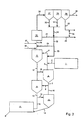
- the process according to the invention is preferably carried out in a fluidized bed reactor with a circulating fluidized bed with an average density of the exhaust gas / solid suspension of 2 to 10 kg / Nm 3 of exhaust gas and an exhaust gas velocity of 3 to 8 m / s, in particular 4 to 5 m / s, carried out.
- the circulating fluidized bed is characterized in that, in contrast to the classic fluidized bed, in which a dense phase is separated from the gas space above by a clear density jump, there are distribution states without a defined limit. A leap in density between the dense phase and the gas space above it does not exist in the case of a circulating fluidized bed, but the solids concentration within the reactor decreases continuously from bottom to top.
- an entrained-flow reactor in which the average density of the exhaust gas / solid suspension is 20 to 200 g of solid / Nm 3 of exhaust gas and the gas velocity is 6 to 20 m / s.
- An entrained flow reactor can advantageously be used for cleaning small amounts of exhaust gas.
- ammonia-releasing compounds are (NH 4 ) SO 4 , (NH 4 ) 2 CO 3 , (NH 4 ) HCO 3 , (COONH 4 ) 2 H 2 O, HCOONH 4 , NH 3 , NH 4 OH, H 2 N -CO-NH 2 , NH 2 CN, Ca (CN) 2 , CaCN 2 , NaOCN, C 2 H 4 N 4 , C 3 H 6 N 6 individually or in a mixture.
- an OH radical generator such as alcohols, sugar, starch, cellulose, can be added to the ammonia-releasing compounds individually or in groups.
Landscapes
- Chemical & Material Sciences (AREA)
- Engineering & Computer Science (AREA)
- Chemical Kinetics & Catalysis (AREA)
- Environmental & Geological Engineering (AREA)
- Health & Medical Sciences (AREA)
- Organic Chemistry (AREA)
- Materials Engineering (AREA)
- Biomedical Technology (AREA)
- Analytical Chemistry (AREA)
- General Chemical & Material Sciences (AREA)
- Oil, Petroleum & Natural Gas (AREA)
- Catalysts (AREA)
- Exhaust Gas Treatment By Means Of Catalyst (AREA)
- Low-Molecular Organic Synthesis Reactions Using Catalysts (AREA)
- Organic Low-Molecular-Weight Compounds And Preparation Thereof (AREA)
Description
Im natürlich vorkommenden Zeolith lassen sich Eisen, Kupfer, Mangan-, Vanadium-, Chrom-, Nickel-, Kobalt-, Zink-, Molybdän-, Niob- und Wolfram-Ionen einzeln oder zu mehreren anstelle der im Gitter vorhandenen Wasserstoffionen und/oder der Alkaliund/oder Erdalkali-Metallionen als katalytisch aktive Substanz einbauen. Dadurch ist gewährleistet, daß die katalytisch aktive Substanz nicht abgerieben wird und demzufolge deren katalytische Wirkung erhalten bleibt.
Zweckmäßigerweise wird das Ammoniak in den Reaktionsraum, in dem die Abgase eine Temperatur von 150 bis 500°C aufweisen und/oder in die Abgasleitung unmittelbar nach dem Anschluß an die Verbrennungseinrichtung, in der die Abgase eine Temperatur von 800 bis 950°C besitzen, eingebracht.
Im Abgas enthaltene geringe Mengen an sauren Schadstoffen, wie SO2, HCl und HF lassen sich dadurch abscheiden, daß die Mischung noch 10 bis 30 Gew.-% CaCO3, CaO und/oder Ca(OH)2 einzeln oder zu mehreren enthält.
Der Sauerstoffgehalt im Reaktionsraum ist > 1 Vol.-%, vorzugsweise 3 bis 12 Vol.-%.
Für die Durchführung des Verfahrens hat sich eine mittlere Teilchengröße des Katalysators d50 < 0,1 mm, vorzugsweise 5 bis 50 mm, als vorteilhaft erwiesen. Bei dieser Teilchengröße wird ein Abbau der Stickoxide von wenigstens 80 % erreicht.
Das erfindungsgemäße Verfahren wird vorzugsweise in einem Wirbelschicht-Reaktor mit zirkulierender Wirbelschicht mit einer mittleren Dichte der Abgas-Feststoff-Suspension von 2 bis 10 kg/Nm3 Abgas und einer Abgasgeschwindigkeit 3 bis 8 m/s, insbesondere 4 bis 5 m/s, durchgeführt. Die zirkulierende Wirbelschicht zeichnet sich dadurch aus, daß im Unterschied zur klassischen Wirbelschicht, bei der eine dichte Phase durch einen deutlichen Dichtesprung von dem darüber befindlichen Gasraum getrennt ist, Verteilungszustände ohne definierte Grenze vorliegen. Ein Dichtesprung zwischen dichter Phase und darüber befindlichem Gasraum ist bei einer zirkulierenden Wirbelschicht nicht existent, jedoch nimmt innerhalb des Reaktors die Feststoffkonzentration von unten nach oben ständig ab.
Claims (12)
- Verfahren zur katalytischen Reduktion von in sauerstoffhaltigen Abgasen von Verbrennungseinrichtungen enthaltenen Stickoxiden, bei dem den eine Temperatur von 150 bis 950 °C aufweisenden Abgasen Ammoniak im Molverhältnis NO:NH3 von 1:0,5 bis 1:1,5 zugesetzt wird und bei dem in einem von den Abgasen mit einer Geschwindigkeit von 1 bis 50 m/s durchströmten Reaktionsraum als Katalysator natürlich vorkommender Zeolith mit 0,1 bis 10 Gew.-% katalytisch aktiver Substanz, bestehend aus einem oder mehreren im Zeolithgitter durch Kationenaustausch eingebauten Metallionen, Kupfer und Eisen, suspendiert ist, dadurch gekennzeichnet, dass eine natürlich vorkommende Zeolith-Mischung, bestehend aus 10 bis 20 Gew.-% Mordenit, 60 bis 70 Gew.-% Clinoptilolit, 0 bis 5 Gew.-% Montmorillonit, Rest SiO2 und eisenhaltige Verbindungen eingesetzt wird.
- Verfahren nach Anspruch 1, dadurch gekennzeichnet, dass die Mischung noch 10 bis 30 Gew.-% CaCO3, CaO und Ca (OH) 2 einzeln oder zu mehreren enthält.
- Verfahren nach einem der Ansprüche 1 und 2, dadurch gekennzeichnet, dass Ammoniak in den Reaktionsraum, in dem die Abgase eine Temperatur von 150 bis 500 °C aufweisen, eingebracht wird.
- Verfahren nach einem der Ansprüche 1 und 2, dadurch gekennzeichnet, dass Ammoniak in die Abgasleitung unmittelbar nach deren Anschluss an die Verbrennungseinrichtung, in der die Abgase eine Temperatur von 800 bis 950 °C aufweisen, eingebracht wird.
- Verfahren nach einem der Ansprüche 1 bis 4, dadurch gekennzeichnet, dass der Sauerstoffgehalt im Reaktionsraum > 1 Vol.-%, vorzugsweise 3 bis 12 Vol.-%, ist.
- Verfahren nach einem der Ansprüche 1 bis 5, dadurch gekennzeichnet, dass die mittlere Teilchengröße des Katalysators d50 < 0,1 mm, vorzugsweise 5 bis 50 µm, beträgt.
- Verfahren nach einem der Ansprüche 1 bis 6, gekennzeichnet, durch die Verwendung eines Wirbelschicht-Reaktors mit zirkulierender Wirbelschicht mit einer mittleren Dichte der Abgas-Feststoff-Suspension von 2 bis 10 kg/Nm3 Abgas und einer Abgasgeschwindigkeit von 3 bis 8 m/s, vorzugsweise 4 bis 5 m/s.
- Verfahren nach einem der Ansprüche 1 bis 6, gekennzeichnet durch die Verwendung eines Flugstromreaktors mit einer mittleren Dichte der Abgas-Feststoff-Suspension von 10 bis 200 g/Nm3 Abgas und einer Abgasgeschwindigkeit von 6 bis 20 m/s beträgt.
- Verfahren nach einem der Ansprüche 1 bis 6, dadurch gekennzeichnet, dass als Reaktionsraum die Abgasleitung im Bereich von deren Anschluss an die Verbrennungseinrichtung und deren Ende vor der Entstaubungseinrichtung verwendet wird.
- Verfahren nach einem der Ansprüche 1 bis 9, dadurch gekennzeichnet, dass als Ammoniak abgebende Verbindungen (NH4) SO4, (NH4)2CO3, (NH4) HCO3, (COONH4) 2H2O, HCOONH4, NH3, NH4OH, H2N-CO-NH2, NH2CN, Ca (CN)2, CaCN2, NaOCN, C2H4N4 und C3H6N6 einzeln oder im Gemisch verwendet werden.
- Verfahren nach Anspruch 10, dadurch gekennzeichnet, dass den Ammoniak abgebenden Verbindungen OH-Radikalbildner, wie Alkohole, Zucker, Stärke und Cellulose einzeln oder zu mehreren zugesetzt werden.
- Verfahren nach einem der Ansprüche 1 bis 11, dadurch gekennzeichnet, dass die aus dem Reaktionsraum ausgetragenen Katalysatorteilchen abgeschieden und in den Reaktionsraum zurückgeführt werden.
Applications Claiming Priority (3)
| Application Number | Priority Date | Filing Date | Title |
|---|---|---|---|
| DE19728699A DE19728699A1 (de) | 1997-07-04 | 1997-07-04 | Verfahren zur katalytischen Reduktion von Stickoxiden |
| DE19728699 | 1997-07-04 | ||
| PCT/EP1998/004122 WO1999001204A1 (de) | 1997-07-04 | 1998-07-03 | Verfahren zur katalytischen reduktion von stickoxiden |
Publications (2)
| Publication Number | Publication Date |
|---|---|
| EP0996494A1 EP0996494A1 (de) | 2000-05-03 |
| EP0996494B1 true EP0996494B1 (de) | 2002-08-28 |
Family
ID=7834710
Family Applications (1)
| Application Number | Title | Priority Date | Filing Date |
|---|---|---|---|
| EP98935017A Expired - Lifetime EP0996494B1 (de) | 1997-07-04 | 1998-07-03 | Verfahren zur katalytischen reduktion von stickoxiden |
Country Status (9)
| Country | Link |
|---|---|
| EP (1) | EP0996494B1 (de) |
| AT (1) | ATE222796T1 (de) |
| AU (1) | AU8440898A (de) |
| DE (2) | DE19728699A1 (de) |
| DK (1) | DK0996494T3 (de) |
| ES (1) | ES2181249T3 (de) |
| PT (1) | PT996494E (de) |
| TW (1) | TW464531B (de) |
| WO (1) | WO1999001204A1 (de) |
Families Citing this family (3)
| Publication number | Priority date | Publication date | Assignee | Title |
|---|---|---|---|---|
| FR2806322B1 (fr) * | 2000-03-14 | 2002-04-26 | Abb Alstom Power Nv | Utilisation de zeolithes pour reduire les emissions d'oxydes nitreux |
| AT500744B8 (de) * | 2005-03-11 | 2007-02-15 | Montanuniv Leoben | Verwendung eines ammoniak abgebenden reststoffes |
| EP1921050A3 (de) | 2006-11-13 | 2009-06-10 | Montanuniversität Leoben | Verfahren und Vorrichtung zur thermischen Behandlung von Rohstoff |
Family Cites Families (10)
| Publication number | Priority date | Publication date | Assignee | Title |
|---|---|---|---|---|
| US4473535A (en) * | 1976-01-26 | 1984-09-25 | Northeast Utilities Service Company | Process for reducing nitric oxides |
| DE3633493A1 (de) * | 1986-10-02 | 1988-04-14 | Metallgesellschaft Ag | Verfahren zur katalytischen reduktion von no |
| FR2622474B2 (fr) * | 1987-04-03 | 1990-01-26 | Azote & Prod Chim | Composition catalytique de reduction selective des oxydes d'azote contenus dans des effluents gazeux oxygenes et procede d'epuration desdits effluents |
| FR2625919B1 (fr) * | 1988-01-19 | 1994-02-11 | Institut Francais Petrole | Procede et catalyseur pour la reduction selective des oxydes d'azote |
| DE3841990A1 (de) * | 1988-12-14 | 1990-06-21 | Degussa | Verfahren zur reduktion von stickoxiden aus abgasen |
| US5171553A (en) * | 1991-11-08 | 1992-12-15 | Air Products And Chemicals, Inc. | Catalytic decomposition of N2 O |
| US5344629A (en) * | 1992-01-03 | 1994-09-06 | A. Ahlstrom Corporation | Reducing Z20 emissions |
| DE69228993T2 (de) * | 1992-06-01 | 1999-12-02 | Kawasaki Jukogyo K.K., Kobe | Verfahren zum behandeln von abgas |
| DE4313479C1 (de) * | 1993-04-24 | 1994-06-16 | Metallgesellschaft Ag | Verfahren zur Entstickung der bei der Herstellung von Zement anfallenden Abgase |
| DE4417453C1 (de) * | 1994-05-19 | 1996-01-04 | Metallgesellschaft Ag | Verfahren zur Entstickung eines Abgases |
-
1997
- 1997-07-04 DE DE19728699A patent/DE19728699A1/de not_active Withdrawn
- 1997-11-14 TW TW086116989A patent/TW464531B/zh not_active IP Right Cessation
-
1998
- 1998-07-03 EP EP98935017A patent/EP0996494B1/de not_active Expired - Lifetime
- 1998-07-03 AU AU84408/98A patent/AU8440898A/en not_active Abandoned
- 1998-07-03 PT PT98935017T patent/PT996494E/pt unknown
- 1998-07-03 WO PCT/EP1998/004122 patent/WO1999001204A1/de not_active Ceased
- 1998-07-03 ES ES98935017T patent/ES2181249T3/es not_active Expired - Lifetime
- 1998-07-03 DE DE59805330T patent/DE59805330D1/de not_active Expired - Fee Related
- 1998-07-03 AT AT98935017T patent/ATE222796T1/de not_active IP Right Cessation
- 1998-07-03 DK DK98935017T patent/DK0996494T3/da active
Also Published As
| Publication number | Publication date |
|---|---|
| DK0996494T3 (da) | 2002-12-09 |
| TW464531B (en) | 2001-11-21 |
| EP0996494A1 (de) | 2000-05-03 |
| PT996494E (pt) | 2002-12-31 |
| DE59805330D1 (de) | 2002-10-02 |
| ATE222796T1 (de) | 2002-09-15 |
| WO1999001204A1 (de) | 1999-01-14 |
| DE19728699A1 (de) | 1999-02-11 |
| AU8440898A (en) | 1999-01-25 |
| ES2181249T3 (es) | 2003-02-16 |
Similar Documents
| Publication | Publication Date | Title |
|---|---|---|
| DE2705901C3 (de) | Verfahren zum Entfernen von Schwefeloxiden und ggf. Stickstoffoxiden aus sauerstoffhaltigen Abgasen | |
| DE112007000814B4 (de) | Verfahren zur Herstellung eines selektiv reduzierenden Katalysators für die Rauchgas-Entstickung und Verfahren zur Entfernung von Stickoxiden aus Rauchgas mit diesem Katalysator | |
| DE69324365T2 (de) | VERFAHREN ZUR ENTFERNUNG VON NOx AUS GASEN DER VERBRENNUNSZONE DURCH ABSORPTION | |
| DE60317667T2 (de) | Oxidation von nox unter verwendung von chlordioxid zusammen mit thermischem verfahren zur beseitigung von nox | |
| DE3438367C2 (de) | Katalysator für die Reinigung eines Abgases | |
| EP0301272A2 (de) | Verfahren und Vorrichtung zur Abgas- oder Abluftreinigung | |
| DD290816A5 (de) | Verfahren zur reduktion von stickoxiden aus abgasen | |
| EP0490414B1 (de) | Verfahren zur Entstaubung, Entschwefelung und Entstickung von Verbrennungsabgasen | |
| DE3903294A1 (de) | Verfahren zur reinigung von schwefelwasserstoffhaltigen gasen | |
| EP0172588B1 (de) | Verfahren zur Abtrennung von NOx und SO2 aus Rauchgasen | |
| EP0762925A1 (de) | Katalysator zur stickoxidminderung in einem strömungsmedium und verfahren zu seiner herstellung | |
| DE3601378A1 (de) | Verfahren zur reinigung von oxide des stickstoffs und schwefels enthaltenden abgasen aus verbrennungsanlagen | |
| EP0274148B1 (de) | Verfahren zur katalytischen Reduktion von in einem Gas enthaltenem NO | |
| DE2520540C3 (de) | Verfahren zum Entfernen von Stickoxiden aus Verbrennungsabgasen | |
| DE3031286C2 (de) | Verfahren zum Behandeln von staub- und schwefeloxidhaltigem Rauchgas | |
| DE2646753B2 (de) | Verfahren zur katalytischen Behandlung von Abgasen | |
| DD268404A1 (de) | Verfahren zum entfernen von so tief x und no tief x aus rauchgas | |
| DE2504027A1 (de) | Verfahren zur entfernung von stickoxiden aus abgasen | |
| EP1406719B1 (de) | Verfahren zum behandeln von ammoniakhaltigen rauchgasen | |
| DE69010909T2 (de) | Verfahren zur reduzierung von nox in einem feuerungsprozess. | |
| CA1125730A (en) | Catalyst for reducing nitrogen oxides and process for producing the same | |
| DE2748471A1 (de) | Katalysatormasse und verfahren zur katalytischen dampfphasenreduktion von stickoxiden | |
| CN208553761U (zh) | 一种荷电喷氨和氨分解组合的烟气脱硝单元及装置 | |
| DE19728699A1 (de) | Verfahren zur katalytischen Reduktion von Stickoxiden | |
| DE3642980C2 (de) |
Legal Events
| Date | Code | Title | Description |
|---|---|---|---|
| PUAI | Public reference made under article 153(3) epc to a published international application that has entered the european phase |
Free format text: ORIGINAL CODE: 0009012 |
|
| 17P | Request for examination filed |
Effective date: 20000204 |
|
| AK | Designated contracting states |
Kind code of ref document: A1 Designated state(s): AT BE CH DE DK ES FI FR GB GR IE IT LI LU NL PT SE |
|
| RAP1 | Party data changed (applicant data changed or rights of an application transferred) |
Owner name: MG TECHNOLOGIES AG |
|
| 17Q | First examination report despatched |
Effective date: 20010612 |
|
| GRAG | Despatch of communication of intention to grant |
Free format text: ORIGINAL CODE: EPIDOS AGRA |
|
| GRAG | Despatch of communication of intention to grant |
Free format text: ORIGINAL CODE: EPIDOS AGRA |
|
| GRAH | Despatch of communication of intention to grant a patent |
Free format text: ORIGINAL CODE: EPIDOS IGRA |
|
| GRAH | Despatch of communication of intention to grant a patent |
Free format text: ORIGINAL CODE: EPIDOS IGRA |
|
| GRAA | (expected) grant |
Free format text: ORIGINAL CODE: 0009210 |
|
| AK | Designated contracting states |
Kind code of ref document: B1 Designated state(s): AT BE CH DE DK ES FI FR GB GR IE IT LI LU NL PT SE |
|
| PG25 | Lapsed in a contracting state [announced via postgrant information from national office to epo] |
Ref country code: IE Free format text: LAPSE BECAUSE OF FAILURE TO SUBMIT A TRANSLATION OF THE DESCRIPTION OR TO PAY THE FEE WITHIN THE PRESCRIBED TIME-LIMIT Effective date: 20020828 Ref country code: GR Free format text: LAPSE BECAUSE OF FAILURE TO SUBMIT A TRANSLATION OF THE DESCRIPTION OR TO PAY THE FEE WITHIN THE PRESCRIBED TIME-LIMIT Effective date: 20020828 |
|
| REF | Corresponds to: |
Ref document number: 222796 Country of ref document: AT Date of ref document: 20020915 Kind code of ref document: T |
|
| REG | Reference to a national code |
Ref country code: GB Ref legal event code: FG4D Free format text: NOT ENGLISH |
|
| REG | Reference to a national code |
Ref country code: CH Ref legal event code: EP |
|
| REF | Corresponds to: |
Ref document number: 59805330 Country of ref document: DE Date of ref document: 20021002 |
|
| REG | Reference to a national code |
Ref country code: IE Ref legal event code: FG4D Free format text: GERMAN |
|
| REG | Reference to a national code |
Ref country code: DK Ref legal event code: T3 |
|
| GBT | Gb: translation of ep patent filed (gb section 77(6)(a)/1977) |
Effective date: 20021209 |
|
| REG | Reference to a national code |
Ref country code: PT Ref legal event code: SC4A Free format text: AVAILABILITY OF NATIONAL TRANSLATION Effective date: 20021021 |
|
| REG | Reference to a national code |
Ref country code: ES Ref legal event code: FG2A Ref document number: 2181249 Country of ref document: ES Kind code of ref document: T3 |
|
| ET | Fr: translation filed | ||
| REG | Reference to a national code |
Ref country code: IE Ref legal event code: FD4D Ref document number: 0996494E Country of ref document: IE |
|
| PLBE | No opposition filed within time limit |
Free format text: ORIGINAL CODE: 0009261 |
|
| STAA | Information on the status of an ep patent application or granted ep patent |
Free format text: STATUS: NO OPPOSITION FILED WITHIN TIME LIMIT |
|
| 26N | No opposition filed |
Effective date: 20030530 |
|
| PGFP | Annual fee paid to national office [announced via postgrant information from national office to epo] |
Ref country code: PT Payment date: 20040617 Year of fee payment: 7 |
|
| PGFP | Annual fee paid to national office [announced via postgrant information from national office to epo] |
Ref country code: FI Payment date: 20040630 Year of fee payment: 7 Ref country code: NL Payment date: 20040630 Year of fee payment: 7 Ref country code: GB Payment date: 20040630 Year of fee payment: 7 |
|
| PGFP | Annual fee paid to national office [announced via postgrant information from national office to epo] |
Ref country code: CH Payment date: 20040702 Year of fee payment: 7 |
|
| PGFP | Annual fee paid to national office [announced via postgrant information from national office to epo] |
Ref country code: SE Payment date: 20040705 Year of fee payment: 7 Ref country code: LU Payment date: 20040705 Year of fee payment: 7 Ref country code: AT Payment date: 20040705 Year of fee payment: 7 |
|
| PGFP | Annual fee paid to national office [announced via postgrant information from national office to epo] |
Ref country code: DK Payment date: 20040706 Year of fee payment: 7 Ref country code: DE Payment date: 20040706 Year of fee payment: 7 |
|
| PGFP | Annual fee paid to national office [announced via postgrant information from national office to epo] |
Ref country code: FR Payment date: 20040708 Year of fee payment: 7 |
|
| PGFP | Annual fee paid to national office [announced via postgrant information from national office to epo] |
Ref country code: ES Payment date: 20040719 Year of fee payment: 7 |
|
| PGFP | Annual fee paid to national office [announced via postgrant information from national office to epo] |
Ref country code: BE Payment date: 20040804 Year of fee payment: 7 |
|
| PG25 | Lapsed in a contracting state [announced via postgrant information from national office to epo] |
Ref country code: LU Free format text: LAPSE BECAUSE OF NON-PAYMENT OF DUE FEES Effective date: 20050703 Ref country code: IT Free format text: LAPSE BECAUSE OF NON-PAYMENT OF DUE FEES;WARNING: LAPSES OF ITALIAN PATENTS WITH EFFECTIVE DATE BEFORE 2007 MAY HAVE OCCURRED AT ANY TIME BEFORE 2007. THE CORRECT EFFECTIVE DATE MAY BE DIFFERENT FROM THE ONE RECORDED. Effective date: 20050703 Ref country code: GB Free format text: LAPSE BECAUSE OF NON-PAYMENT OF DUE FEES Effective date: 20050703 Ref country code: AT Free format text: LAPSE BECAUSE OF NON-PAYMENT OF DUE FEES Effective date: 20050703 |
|
| PG25 | Lapsed in a contracting state [announced via postgrant information from national office to epo] |
Ref country code: SE Free format text: LAPSE BECAUSE OF NON-PAYMENT OF DUE FEES Effective date: 20050704 Ref country code: ES Free format text: LAPSE BECAUSE OF NON-PAYMENT OF DUE FEES Effective date: 20050704 |
|
| PG25 | Lapsed in a contracting state [announced via postgrant information from national office to epo] |
Ref country code: FI Free format text: LAPSE BECAUSE OF NON-PAYMENT OF DUE FEES Effective date: 20050710 |
|
| PG25 | Lapsed in a contracting state [announced via postgrant information from national office to epo] |
Ref country code: LI Free format text: LAPSE BECAUSE OF NON-PAYMENT OF DUE FEES Effective date: 20050731 Ref country code: CH Free format text: LAPSE BECAUSE OF NON-PAYMENT OF DUE FEES Effective date: 20050731 Ref country code: BE Free format text: LAPSE BECAUSE OF NON-PAYMENT OF DUE FEES Effective date: 20050731 |
|
| PG25 | Lapsed in a contracting state [announced via postgrant information from national office to epo] |
Ref country code: DK Free format text: LAPSE BECAUSE OF NON-PAYMENT OF DUE FEES Effective date: 20050801 |
|
| PG25 | Lapsed in a contracting state [announced via postgrant information from national office to epo] |
Ref country code: PT Free format text: LAPSE BECAUSE OF NON-PAYMENT OF DUE FEES Effective date: 20060103 |
|
| PG25 | Lapsed in a contracting state [announced via postgrant information from national office to epo] |
Ref country code: NL Free format text: LAPSE BECAUSE OF NON-PAYMENT OF DUE FEES Effective date: 20060201 Ref country code: DE Free format text: LAPSE BECAUSE OF NON-PAYMENT OF DUE FEES Effective date: 20060201 |
|
| REG | Reference to a national code |
Ref country code: CH Ref legal event code: PL |
|
| EUG | Se: european patent has lapsed | ||
| GBPC | Gb: european patent ceased through non-payment of renewal fee |
Effective date: 20050703 |
|
| PG25 | Lapsed in a contracting state [announced via postgrant information from national office to epo] |
Ref country code: FR Free format text: LAPSE BECAUSE OF NON-PAYMENT OF DUE FEES Effective date: 20060331 |
|
| NLV4 | Nl: lapsed or anulled due to non-payment of the annual fee |
Effective date: 20060201 |
|
| REG | Reference to a national code |
Ref country code: DK Ref legal event code: EBP |
|
| REG | Reference to a national code |
Ref country code: FR Ref legal event code: ST Effective date: 20060331 |
|
| REG | Reference to a national code |
Ref country code: ES Ref legal event code: FD2A Effective date: 20050704 |
|
| BERE | Be: lapsed |
Owner name: *MG TECHNOLOGIES A.G. Effective date: 20050731 |