EP0996077A2 - Système de balayage optique, lecteur de code, lecteur de code à barres, à degrée de liberté élevé du placement des pièces optiques - Google Patents
Système de balayage optique, lecteur de code, lecteur de code à barres, à degrée de liberté élevé du placement des pièces optiques Download PDFInfo
- Publication number
- EP0996077A2 EP0996077A2 EP99120078A EP99120078A EP0996077A2 EP 0996077 A2 EP0996077 A2 EP 0996077A2 EP 99120078 A EP99120078 A EP 99120078A EP 99120078 A EP99120078 A EP 99120078A EP 0996077 A2 EP0996077 A2 EP 0996077A2
- Authority
- EP
- European Patent Office
- Prior art keywords
- scanning
- light
- pattern
- bar code
- mirror
- Prior art date
- Legal status (The legal status is an assumption and is not a legal conclusion. Google has not performed a legal analysis and makes no representation as to the accuracy of the status listed.)
- Granted
Links
Images


Classifications
-
- G—PHYSICS
- G02—OPTICS
- G02B—OPTICAL ELEMENTS, SYSTEMS OR APPARATUS
- G02B26/00—Optical devices or arrangements for the control of light using movable or deformable optical elements
- G02B26/08—Optical devices or arrangements for the control of light using movable or deformable optical elements for controlling the direction of light
- G02B26/10—Scanning systems
-
- G—PHYSICS
- G06—COMPUTING; CALCULATING OR COUNTING
- G06K—GRAPHICAL DATA READING; PRESENTATION OF DATA; RECORD CARRIERS; HANDLING RECORD CARRIERS
- G06K7/00—Methods or arrangements for sensing record carriers, e.g. for reading patterns
- G06K7/10—Methods or arrangements for sensing record carriers, e.g. for reading patterns by electromagnetic radiation, e.g. optical sensing; by corpuscular radiation
- G06K7/10544—Methods or arrangements for sensing record carriers, e.g. for reading patterns by electromagnetic radiation, e.g. optical sensing; by corpuscular radiation by scanning of the records by radiation in the optical part of the electromagnetic spectrum
- G06K7/10821—Methods or arrangements for sensing record carriers, e.g. for reading patterns by electromagnetic radiation, e.g. optical sensing; by corpuscular radiation by scanning of the records by radiation in the optical part of the electromagnetic spectrum further details of bar or optical code scanning devices
- G06K7/1096—Methods or arrangements for sensing record carriers, e.g. for reading patterns by electromagnetic radiation, e.g. optical sensing; by corpuscular radiation by scanning of the records by radiation in the optical part of the electromagnetic spectrum further details of bar or optical code scanning devices the scanner having more than one scanning window, e.g. two substantially orthogonally placed scanning windows for integration into a check-out counter of a super-market
-
- G—PHYSICS
- G06—COMPUTING; CALCULATING OR COUNTING
- G06K—GRAPHICAL DATA READING; PRESENTATION OF DATA; RECORD CARRIERS; HANDLING RECORD CARRIERS
- G06K7/00—Methods or arrangements for sensing record carriers, e.g. for reading patterns
- G06K7/10—Methods or arrangements for sensing record carriers, e.g. for reading patterns by electromagnetic radiation, e.g. optical sensing; by corpuscular radiation
- G06K7/10544—Methods or arrangements for sensing record carriers, e.g. for reading patterns by electromagnetic radiation, e.g. optical sensing; by corpuscular radiation by scanning of the records by radiation in the optical part of the electromagnetic spectrum
- G06K7/10554—Moving beam scanning
- G06K7/10564—Light sources
- G06K7/10574—Multiple sources
-
- G—PHYSICS
- G06—COMPUTING; CALCULATING OR COUNTING
- G06K—GRAPHICAL DATA READING; PRESENTATION OF DATA; RECORD CARRIERS; HANDLING RECORD CARRIERS
- G06K7/00—Methods or arrangements for sensing record carriers, e.g. for reading patterns
- G06K7/10—Methods or arrangements for sensing record carriers, e.g. for reading patterns by electromagnetic radiation, e.g. optical sensing; by corpuscular radiation
- G06K7/10544—Methods or arrangements for sensing record carriers, e.g. for reading patterns by electromagnetic radiation, e.g. optical sensing; by corpuscular radiation by scanning of the records by radiation in the optical part of the electromagnetic spectrum
- G06K7/10554—Moving beam scanning
- G06K7/10594—Beam path
- G06K7/10603—Basic scanning using moving elements
- G06K7/10613—Basic scanning using moving elements by rotation, e.g. polygon
- G06K7/10623—Constructional details
Definitions
- the present invention relates to an optical scanner which is used for bar code readers and the like. More particularly, the present invention relates to a multi-head optical scanner used for a bar code reader and having placement of optical parts to reduce size and improve code reading.
- Point-of-sale and other systems are widely used to perform checkout counter operations by reading bar code information attached to products.
- bar code information is input by scanning the product and checkout operations are performed based on the information input in this manner, thus reducing the workload for the operator at the checkout counter.
- So-called stationary type scanners which are fixed to the checkout counter are most often used in POS systems.
- the conventional devices typically include a simple reading window and emit an outgoing scanning pattern to scan the bar code from the window.
- the conventional reading window is generally either the type placed horizontally on the surface of the counter or the type placed vertically on the surface of the counter.
- the direction at which the bar code can be read i.e., the bar code orientation
- the direction at which the bar code can be read is restricted so that the operator has to point the bar code in the direction of the reading window, thus adding to the workload of the operator.
- the known multi-head scanners include a window which is horizontal to the surface of the counter (bottom window) and a window which stands vertically to the surface of the counter (side window).
- the multi-head scanners proposed thus far have presented the following problems. Firstly, the thickness of a bottom part of the conventional multi-head scanner device has been problematical. In Europe, it has been mandated by law that the checkout counter operators performing checkout operations be seated while working. The scanners are embedded in the surface of the counter so that when the scanner is thick, it is possible that the scanner will stick out from the bottom surface of the counter. In the case that the scanner sticks out from the bottom surface of the counter, the operator is faced with an increased workload because it is no longer possible for him to place his knees below the surface of the counter, and the operability of the bar code reading operation is deteriorated since the height of the scanning surface is increased. However, when the checkout counter operator carries out the bar code reading operations in a standing position, the difficulties discussed above do not occur.
- the checkout counter often has a drawer holding cash positioned below the scanner.
- a drawer holding cash is positioned below the scanner, problems occur in that when the scanner is thick, the distance between the operator and the cash drawer increases, and it is awkward for the operator to put cash into the drawer and remove cash from the drawer adroitly.
- multi-head scanners cannot handle total 360° reading.
- the greatest characteristic of multi-head scanners is that they can read a bar code regardless of the direction in which the bar code is pointed.
- the multi-head scanner since the multi-head scanner has an outgoing scanning pattern for the bottom part and the side part, respectively, the scanner can read the bar code information even if the bar code is not pointed in the direction of the reading window.
- the conventional multi-head scanner results in problems in that it is no longer possible to read the bar code because of the incline between the bar code and the counter surface and total 360° reading is not possible.
- the multi-scanning light pattern referred to here is the general name for the scanning pattern outgoing from the bottom part and the scanning pattern outgoing from the side part.
- the conventional multi-head scanners include multiple light sources which provide incident light beams from the respective light sources to a scanning means of a polygon mirror and the like.
- the light beams outgoing from a single light source are split by a beam splitter, and the respective light sources are incident from different directions to the scanning means.
- the number of light beams incident to the scanning means is increased in the above manner, it is necessary to provide as many light detection devices to receive reflective light from the bar code, and as many converging means to provide incident reflected light to the light detection devices as there are light beams.
- problems arise in that the size and cost of the scanner are increased.
- An embodiment of the present invention can overcome the above-described problems of the prior art and provide an optical scanner which reduces the thickness of a bottom part of the optical scanner.
- An embodiment of the present invention can provide an optical scanner having a bottom part with a thickness of 90mm and below.
- An embodiment of the present invention can provide a multi-head optical scanner and other types of optical scanners which can ensure virtually perfect 360° reading.
- An embodiment of the present invention can provide an optical scanner which uses a single light beam incident on the scanning device and which can generate multi-scanning patterns.
- an optical scanner which emits a first scanning pattern upward from a horizontal plane surface and emits a second scanning pattern to a side from a plane surface which is vertical relation to the horizontal plane surface
- the optical scanner comprising: a light source to emit light beams; a scanning device to scan the light beams emitted from the light source, the scanning device including a rotation axis; and a drive device to drive the scanning device, wherein the scanning device is positioned so that the rotation axis of the scanning device is approximately horizontal to the horizontal plane surface.
- the surface from which the second scanning pattern is emitted does not have to be vertical to the horizontal plane, and the angle formed by the horizontal plane and the surface which is vertical to the horizontal plane need not be a 90° angle.
- the angle formed by the surface from which the second scanning pattern is emitted and the horizontal plane may be other than a 90° angle.
- the light source may be positioned so that light beams are emitted in a direction which is nearly vertical relative to the horizontal plane.
- a code reader comprising a bottom part embedded in a surface of a counter and emitting a first scanning pattern to read a code optically; a side part, positioned vertically to the bottom part, and emitting a second scanning pattern different from the first scanning pattern to read the code optically; and a speaker positioned facing a user at a top center of the side part to emit a sound indicating to the user that the code has been read.
- a code reader comprising a bottom part embedded in a surface of a counter to emit a first scanning pattern to optically read a code; a side part, positioned vertically to the bottom part, to emit a second scanning pattern different from the first scanning pattern to optically read the code; and a light receiving device mounted on a substrate to receive light reflected from the code, wherein the substrate is positioned in a direction skirting the orientation of a back wall surface of the side part.
- the light receiving device may include a light-receiving surface which faces downward.
- an optical scanner comprising a light source to emit light beams; a scanning device to scan the light beams emitted from the light source; a scanning pattern mirror to reflect scanned light generated by the scanning device, the scanning pattern mirror including a plurality of mirrors to generate scanning beams which make up the scanning patterns; and an opening from which the scanning beams are emitted, wherein the scanning beams are emitted from the opening after being reflected by the plurality of mirrors.
- an optical scanner comprising a light source to emit light beams; a scanning device to scan light beams emitted from the light source; a scanning pattern mirror to reflect scanned light generated by the scanning device, the scanning pattern mirror including a plurality of mirrors to generate scanning patterns comprising scanning beams; and an opening from which the scanning beams are emitted, wherein a first scanning light is scanned in a first direction on at least one of the plurality of mirrors which make up the scanning pattern mirrors; and a second scanning light is scanned in a second direction intersecting the first direction on at least one of the plurality of mirrors which make up the scanning pattern mirror.
- an optical scanner comprising a light source to emit light beams; a scanning device to scan the light beams emitted from the light source; a pattern mirror including a plurality of mirrors to reflect scanning light generated by the scanning device; and an opening through which the scanning light reflected by the pattern mirror is passed, wherein a first scanning light is scanned in a first direction on a first virtual surface outside the opening, and a second scanning light is scanned in a direction nearly forming a right angle with the first direction on the virtual surface, and both the first and second scanning lights are emitted from the opening after being reflected jointly by at least two common mirrors of the mirrors which make up the pattern mirror.
- a bar code reader positioned on top of a counter, the bar code reader comprising a bottom part body having a first surface which is horizontal to a surface of the counter; and a side part body having a second surface positioned at approximately a right angle to the first surface, wherein a thickness of a portion of the bottom part body which is positioned underneath the counter is 90 mm or less.
- a bar code reader located on top of a counter, comprising a bottom part body having a first surface which is horizontal to a surface of the counter; a side part body having a second surface which forms approximately a right angle to the first surface; a light source to emit light beams; a scanning device to scan light emitted from the light source; a light receiving device to receive reflected light from the bar code; and a converging device to converge reflected light from the bar code to the light receiving device, wherein the light source and the scanning device are located inside the side part body.
- scanning device may be placed at a position which is higher than the surface of the counter on which the bar code reader is placed.
- an optical scanner which emits a first scanning pattern upward from a horizontal plane and a second scanning pattern sideways vertical to the horizontal plane, comprising a light source to emit light beams; a scanning device having a reflecting surface to reflect light beams emitted from the light source; and a drive device to drive the scanning device, wherein the scanning device is positioned so that light beams are reflected downward.
- an optical scanner comprising a bottom part which is embedded in the surface of a counter; and a side part positioned vertically to the bottom part, wherein different scanning patterns are respectively emitted from the bottom part and the side part.
- the optical scanner may include a scanning device having a reflective surface wherein the reflective surface of the scanning device reflects the light beams downward.
- a code reader which reads code after emitting scanning light and detecting the light reflected from objects, comprising a first scanning light which is scanned in a first direction; and a second scanning light which is scanned in a direction intersecting with the first scanning light, both scanning lights passing through the same optical path.
- the bar code reader (hereinafter referred to simply as "device") described hereinbelow in accordance with embodiments of the present invention is preferably a so-called multi-head scanner which is embedded in a checkout counter.
- the outside structure of the device may take the form of any of the many types of multi-head scanners currently in use. Accordingly, no drawing of the outside of the device is provided.
- the device includes a bottom window 3 placed at a position which is parallel to a surface (product scanning surface) of the checkout counter 2 and a side window 14 placed so that it preferably forms a right angle to the surface of the checkout counter 2.
- a scanning pattern which is made up of a plurality of scanning beams, is emitted from these respective windows 3, 14 to read the bar code.
- the entire portion of the bar code reader on which the bottom window 3 is placed is referred to hereinafter as the "bottom part" 1; the entire portion of the bar code reader on which the side window 14 is placed is referred to hereinafter as the "side part" 4.
- a surface of the device to which the bottom window 3 is fixed is positioned so that it is level with the checkout counter 2 surface so that a product can be slid on the checkout counter 2 and the bar code read.
- the side window 14 is also disposed to face the operator carrying out the bar code reading operations.
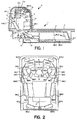
- FIGS. 1-3 are diagrams providing an internal view of the device in accordance with the first embodiment of the present invention. More particularly, FIG. 1 is an internal side view, FIG. 2 is an internal upper view, and FIG. 3 is an internal frontal view of the bar code reading device in accordance with the first embodiment of the present invention.
- FIG. 3A is a frontal cross-sectional view taken near an extended line of the side window 14.
- FIG. 3B is a frontal cross-sectional view of the front end of the device.
- the device comprises a bottom part 1 positioned generally underneath the surface of the counter 2, and a side part 4 which is vertical or approximately vertical to the surface of the counter 2.
- the bottom part 1 includes in a surface thereof a bottom window 3 which is level with the surface of the counter 2.
- the bottom window 3 is level with the surface of the counter 2 to accommodate instances in which a product is slid on the surface of the counter 2 to read the bar code.
- the counter 2 surface is also known as the "product sliding surface.
- the bottom part 1 is preferably relatively long, and the side part 4 is preferably relatively short.
- the device includes a light source 5, such as a laser diode, which emits laser beams; a polygon mirror 6, which is an example of a scanning device, to scan the laser beams emitted from the light source 5; a pattern mirror comprising several mirrors, which will be described in greater detail hereinbelow, to generate scanning beams which make up the scanning pattern by suitably reflecting the light beams scanned by the polygon mirror 6; a light detector 8 which receives light reflected from the bar code and outputs electrical signals according to the quantity of light received; an analog-to-digital conversion circuit 9 (hereinafter referred to as "A/D circuit", or simply “substrate”) which binomializes the signals (analog signals) output from the light detector 8; and a main printed substrate 10 (main PCB) including a decoder to demodulate the bar code based on the digital signals output from the A/D circuit 9.
- the reflected light which is incident on the light detector 8 is converged and reflected from a conca
- the light source 5 is preferably a laser light source unit including a collimator (not shown) and an aperture (not shown), which are laser beam reshaping means, to reshape the laser beams emitted from the laser diode and a driver circuit (not shown) to drive the laser light source 5.
- the laser beam reshaping means and the driver circuit preferably form an integral piece.
- the light source 5 is positioned at the lower left-hand part of the device shown in FIG. 1, that is, the lower portion of the body of the side part 4. Laser beams are emitted upward from the light source 5 in the lower part of the device.
- the laser light is emitted from the light source 5 nearly vertically upwards.
- the direction in which the laser light is emitted from the light source 5 i.e., the outgoing angle
- Prior art multi-head scanners which are placed on the checkout counter in the same manner as described above in accordance with the first embodiment of the invention, do not have a configuration in which light beams are emitted upward without splitting the light beams.
- the polygon mirror 6 is placed near the center of the body of the side part 4.
- the polygon mirror 6 in accordance with the first embodiment of the invention preferably includes four reflective surfaces each having slightly different slopes. Since the respective slopes of each of the four reflective surfaces are different, the polygon mirror 6 can generate four parallel scanning lights.
- the polygon mirror 6 is driven to rotate by a motor 12 to scan the incident laser light.
- the motor 12 includes a rotation shaft 12a.
- a base portion of the polygon mirror 6 is made of molded resin with a hole formed therein.
- the rotation shaft 12a of the motor 12 is inserted into the hole in the base portion of the polygon mirror 6.
- the polygon mirror 6 has a rotation axis 6a positioned so that it is nearly parallel with the bottom window 3, which is essentially the same as the surface on which the product is slid.
- the rotation axis 6a is preferably at an angle of approximately 5° with respect to the horizontal, with the side of the rotation axis 6a nearer to the bottom window 3 facing downwards.
- the slope of the rotation axis 6a of the polygon mirror 6 can be varied as is suitable according to the design.
- the polygon mirror 6 in accordance with the first embodiment of the present invention is configured so that the laser light is incident on the polygon mirror 6 upward from the bottom of the device and the scanning light is reflected and outgoing downward from the polygon mirror 6.
- the reflective surface of the polygon mirror 6 can be thought of as being directed downward.
- there are also reflective surfaces which are directed upward these surfaces are not used to reflect incident laser light because a laser light beam cannot be emitted to all of the reflective surfaces at once. If one takes into consideration only reflective surfaces which operate effectively, the reflective surface may be thought of as directed downward.
- a vibrating mirror may be used to reflect the laser light instead of a polygon mirror.
- the first embodiment of the present invention differs from and is advantageous over the prior art multi-head scanner in at least the following points.
- the rotation axis of a polygon mirror is placed so that it is nearly vertical to the bottom window.
- the prior art polygon mirror is basically placed inside the body of the bottom part or below the body of the side part. Therefore, there is a limit as to how freely the optical parts can be disposed inside the bottom pan of the prior art optical scanners.
- the light source 5 and scanning device are positioned such that neither the light source 5 nor the scanning device is disposed inside the body of the bottom part 1.
- the light reflected from the bar code is divergent light.
- the quantity of reflected light which is received from the bar code should, insofar as possible, be increased in order to upgrade the reading performance of the bar code.
- the pattern mirror functions to send incident reflected light from the bar code to the light detector 8. As a result, the pattern mirror should be made as large as possible. The device in accordance with the first embodiment of the present invention satisfies these needs.
- the light detector 8 is attached to the substrate on which the A/D circuit 9 is mounted so that the light detector 8 forms an integral piece with the substrate 9.
- the substrate 9 is attached near the back of the body of the side part 4 at a position which is nearly parallel to the surface of the wall of the side part 4.
- the light-receiving surface of the light detector 8 is directed downward. Light converged from the concave mirror 11 is incident on the light-receiving surface of the light detector 8.
- the concave mirror 11 converges signal light and is disposed in the middle of an optical path between the light source 5 and the polygon mirror 6.
- the reflective surface of the concave mirror 11 is directed to the light detector 8 and functions to converge and reflect the light reflected (signal light) from the bar code which is incident on the light detector 8 via the polygon mirror 6.
- a hole is formed at the middle of the concave mirror 11 so that the laser light emitted from the light source 5 is incident to the polygon mirror 6.
- the main PCB 10 is positioned on the bottom surface of the body of the side part 4.
- the main PCB 10 has mounted thereon a decoding device (not shown), an interface connector 13 used to transmit decoded signals to the POS terminal and other external devices, and a voltage conversion device (not shown) which converts a power source voltage supplied from the outside via an AC adapter (not shown) or the like to a voltage which is suitable for the device.
- the main PCB 10 controls the lighting of the light source 5, the driving of the polygon mirror 6, motor 12 and the operation of the A/D circuit 9.
- the laser light beams projected from the light source 5 are reshaped using a collimator lens and an aperture so that they are provided with the resolving power required to read the bar code, and are then incident on the polygon mirror 6 via the hole in the middle of the concave mirror 11.
- the four reflective surfaces of the polygon mirror 6 all have different slopes so that four parallel scanning lights are generated by the polygon mirror 6.
- the scanning light from the polygon mirror 6 is projected downward, as shown in the FIG. 1.
- the scanning light generated from the polygon mirror 6 is suitably split and reflected from a pattern minor, which operates as a scanning line splitting means, and which is placed on the bottom part 1 and the side part 4 and is emitted as a scanning pattern from the bottom window 3 and the side window 14.
- the scanning pattern is comprised of multiple scanning lines which are scanned in different directions. The scanning direction and angle of the respective scanning lines are determined by the slope of the pattern mirror.
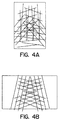
- FIGS. 4A through FIG. 8 are diagrams illustrating the scanning pattern which is output from the bottom window 3 (bottom pattern) and the scanning pattern which is output from the side window 4 (side pattern). More particularly, FIG. 4A is a diagram of the bottom pattern, and FIG. 4B is a diagram of the side pattern at the respective window surfaces. In FIGS. 4A and 4B, the rectangular portion surrounding the scanning pattern is the frame of the window.
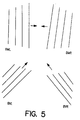
- FIG. 5 and FIG. 6 are diagrams of the scanning patterns which make up the bottom pattern;
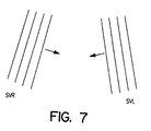
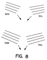
- FIG. 7 and FIG. 8 are diagrams of the scanning patterns which make up the side pattern, the scanning patterns being split respectively.
- the scanning pattern which is output from the bottom window 3 is comprised of the following eight (8) scanning patterns BMR, BML, BVR, BVL, BCR, BCL, BOR, BOL. Further, each of the scanning patterns is preferably comprised of four parallel scanning lines. However, the lines forming the scanning patterns do not have to comprise completely parallel scanning lines, although they may be thought of as parallel here, and the same holds true throughout.
- FIG. 4A illustrates the overall bottom pattern in the bottom window 3.
- FIG. 5 and FIG. 6 are diagrams illustrating splitting of various scanning patterns which make up the bottom pattern. More particularly, FIG. 5 illustrates scanning patterns BML, BMR, BVL, BVR. FIG. 6 illustrates scanning patterns BCL, BCR, BOL, BOR. Further, the top part of FIG. 4A illustrates the side near the side window 14. The arrows in FIG. 5 and FIG. 6 indicate the general outgoing direction of each of the scanning patterns on a flat surface.
- BVR and BVL are respectively scanned in a direction which is preferably nearly vertical to the surface of the bottom window 3.
- the other scanning patterns are scanned in a direction which is preferably nearly parallel to the surface of the bottom window 3.
- the directions of scanning of the scanning patterns are not limited to completely vertical/horizontal directions, and the directions of scanning may be slightly inclined with respect to vertical and horizonal.
- the directions of scanning may both be thought of as vertical/horizontal.
- the scanning directions of the scanning patterns are not restricted to the ones shown in the figures, but may be varied as is suitable.
- the scanning patterns BOR and BOL are not, strictly speaking, completely symmetrical on the left and right.
- the scanning positions on the left and right are configured by intentionally moving or adjusting them so as to increase the probability of reading (scanning) the bar code.
- the scanning pattern output from the side window 14 is comprised of the following six scanning patterns SVR, SVL, SHTR, SHTL, SHDR, SHDL. These six scanning patterns are comprised of four parallel scanning lines.
- FIG. 4B is an overall view of the side pattern on the side window 14 surface in accordance with the first embodiment of the present invention.
- FIG. 7 and FIG. 8 are diagrams illustrating the splitting of each of the scanning patterns which make up the side pattern. In a manner similar to the scanning patterns shown in FIG. 5 and FIG. 6, the arrows in FIG. 7 and FIG. 8 indicate the outgoing direction of each of the scanning patterns on a plane surface.
- SVR and SVL are scanned in a direction which is nearly vertical to the surface of the bottom window 3.
- the other scanning patterns SHTR, SHTL, SHDR and SHDL are scanned in a direction which is nearly horizontal to the surface of the bottom window 3.
- the actual scanning directions are not completely vertical or horizontal, but are somewhat inclined, as can be seen from FIG. 8. Nevertheless, in accordance with embodiments of the present invention, the scanning patterns can be considered to be scanned in a vertical/horizontal direction.
- the scanning light generated from the polygon mirror 6 next scans the pattern mirror in the following sequence SVL1 ⁇ SHR1 ⁇ BMR1 ⁇ BVR1 ⁇ BZ1 ⁇ BVL1 ⁇ BML1 ⁇ SHL1 ⁇ SVR1. Further, the pattern mirror is shown in FIG. 4 through FIG. 6.
- the first letters of the notation attached to the pattern mirror indicate whether the pattern mirror corresponds to the bottom pattern or the side pattern.
- the pattern mirror which begins with the letter B corresponds to the bottom pattern
- the pattern mirror which begins with the letter S corresponds to the side pattern.
- the letter V indicates that the related scanning pattern is scanned in a vertical direction
- the letter H indicates that the related scanning pattern is scanned in a horizontal direction
- the letter L indicates that the related scanning pattern is emitted from the left side of the scanner
- the letter R indicates that the related scanning pattern is emitted from the right side of the scanner
- the letter T indicates that the related scanning pattern is emitted from the top side (upper portion) of the side window
- the letter D indicates that the related scanning pattern is emitted from the bottom side (lower portion) of the side window.
- the letters Z and M do not have any specific meaning.
- the reflecting surfaces of the pattern mirrors are directed toward the polygon mirror 6 and are disposed in a fan shape.
- the pattern mirror corresponding to the bottom pattern reflects scanning light incident from the polygon mirror 6 to the bottom part 1
- the pattern mirror corresponding to the side pattern reflects scanning light incident from the polygon mirror 6 to the side part 4.
- the bottom pattern mirror which generates the bottom pattern is disposed on the bottom part of the device and comprises the following mirrors.
- mirrors are disposed so that they are nearly symmetrical to the centerline of the device.
- the five mirrors BZ1, BVR1, BVL1, BMR1 and BML1 are disposed on the bottom of the side part 4 and their reflective surfaces are directed toward the bottom part 1.
- the four mirrors BZR3, BZL3, BMR4, BML4 are disposed on the bottom surface of the bottom part 1.
- the respective reflective surfaces of the seven mirrors BMR2, BML2, BMR3, BML3, BHR2, BHL2 and BZ2 are inclined slightly downward and are disposed on the side wall of the bottom part 1.
- the outside parts of the mirrors BZR3 and BZL3 are respectively inclined somewhat upwards, as is shown in FIG. 3.
- a space can be ensured between the bottom of the bottom pan 1 and the pattern mirror (for example, BZL3).
- a cable or the like may be set in place in the space between the bottom of the bottom part 1 and the pattern mirror (in FIG. 3, the cable is a dark circle).
- Pattern mirrors BMR4 and BML4 are also provided with the same type of incline as pattern mirrors BZR3 and BZL3.
- the scanning line which makes up the bottom pattern is first reflected from the polygon mirror 6 and then is emitted from the bottom window 3 after traveling through the following paths.
- the paths BCR (BCL) and BOR (BOL) use the same two pattern mirrors BZ1 and BZR3 (BZL3), the only difference being the path of part of BZ2 and BHR2 (BHL2) between them.
- the paths BOR (BOL) and BVR (BVL) both use the same two pattern mirrors BHR2 (BHL2) and BZR3 (BZL3), so that BZ1 and BVR1 (BVL1), which are the pattern mirrors in which the scanning light scanned from the polygon mirror 6 is first incident, are different.
- the number of pattern mirrors which must be accommodated inside the bottom part 1 can be reduced by adopting the above configuration. Therefore, in accordance with the present invention, since the overall number of pattern mirrors is reduced, if the mirrors are accommodated inside the same space, the area per single mirror can be increased and the converging efficiency of the light reflected from the bar code can be upgraded.
- the side pattern mirror which generates the side pattern is comprised of the following mirrors SVR1, SVL1, SVR2, SVL2, SHR1, SHL1, SHTR2, SHTL2, SHTR3, SHTL3, SHDR2, SHDL2, SHDR3, SHDL3.
- the pattern mirrors which generate the side pattern are disposed so that they are nearly symmetrical to the middle line of the device in the same manner as the bottom pattern mirror. Furthermore, the four pattern mirrors SHTR2, SHTL2, SHDR2, SHDL2 are disposed with the respective reflecting sides pointed downwards.
- the respective scanning patterns which make up the side pattern are first scanned by the polygon mirror 6 and then are emitted from the side window 14 after traveling through the following paths.
- SHR1 SHL1
- SHTL SHTR
- SHDL SHDR
- FIG. 9 is an internal side view of the bar code reader showing placement of specific pattern mirrors in accordance with the first embodiment of the present invention.
- the straight lines drawn in each of the pattern mirrors indicate the scanning locus of the scanning line in each of the pattern mirrors.
- the two outermost scanning lines of the four parallel scanning lines are indicated.
- the two scanning lines drawn in BML3 in the figure are not strictly parallel, they may be considered "parallel" for all intents and purposes.
- BHR2 is scanned by two types of scanning lines which are nearly vertical to a nearly horizontal plane.
- FIG. 10 is an internal frontal view of the bar code reader showing placement of specific pattern mirrors in accordance with the first embodiment of the present invention. More particularly, FIG. 10 shows only a specified pattern mirror, specifically, the pattern mirror which is accommodated inside the body of the side part 4. Further, pattern mirror SVR2 is not shown in FIG. 10, which forms a pair with the pattern mirror SVL2. The locus of the scanning line is delineated by the unbroken line in the pattern mirror which is shown in FIG. 10.
- FIG. 11 and FIG. 12 are internal upper views of the bar code reader showing placement of specific pattern mirrors in accordance with the first embodiment of the present invention. More specifically, FIG. 11 shows the respective pattern mirrors having reflective surfaces which face upwards, while FIG. 12 shows the respective pattern mirrors having reflective surfaces which face downward.
- BZL3 and BZR3 are scanned by a total of three scanning lines which intersect each other, while BML4 and BMR4 are also scanned by three types of scanning lines which intersect each other to form a right angle.
- FIG. 13 is an explanatory diagram illustrating a locus scanned by the scanning pattern during a bar code reading process when the bar code is vertical to the bottom window 3 in accordance with the first embodiment of the present invention.
- the bar code should be scanned from the scanning pattern which nearly coincides with the direction of the bar code, that is, the scanning pattern which is emitted toward the bar code and which is scanned vertically to the bottom window 3. More specifically, these are (1) both patterns SVR and SVL which are emitted from the side window 14 and (2) both patterns BVR and BVL which are emitted from the bottom window 3.
- a product with a bar code attached is moved from the right of the device to the left side toward the side window 14.
- the bar code is moved as shown in FIG. 13: (1) when the bar code is nearly facing the side window 14; (2) when the bar code faces the direction in which the product is moved; (3) when the bar code faces a direction opposite to that in which the product is moved; and (4) when the bar code faces the operator (not facing the side window 14).
- FIGS. 14A-14D are diagrams illustrating a relationship between the bar code and the scanning pattern which scans the bar code for the four cases indicated above in accordance with embodiments of the present invention.
- FIG. 14A is a diagram illustrating the case in which the bar code faces the side window 14.
- the bar code is scanned from the SVR pattern and SVL pattern emitted from the side window 14 and then read.
- FIG. 14B is a diagram illustrating the case in which the bar code faces the direction in which the product is moved.
- the bar code is scanned from the SVR pattern emitted from the side window 14 and the BVL pattern emitted from the bottom window 3.
- FIG. 14C is a diagram illustrating the case in which the bar code faces the direction opposite to that in which the product is moved.
- the bar code is scanned from the SVL pattern emitted from the side window 14 and the BVR pattern emitted from the bottom window 3.
- FIG. 14D is a diagram illustrating the case in which the bar code faces the operator.
- the bar code is not scanned by the scanning line emitted from the side window 14. Instead, the bar code is scanned and read by the BVR pattern and the BVL pattern which are emitted facing the side window 14.
- FIG. 15 is an explanatory diagram illustrating a process for reading a bar code when the bar code is placed parallel to the bottom window 3 and which indicates the scanning locus scanned by the scanning pattern when the bar code is nearly horizontal to the bottom window 3 in accordance with embodiments of the present invention.
- the bar code is scanned using the scanning pattern scanned in a direction which is parallel to the bottom window 3.
- the direction in which the product is moved has the same conditions as that shown in FIG. 13, specifically, the product is moved from the right of the device to the left side toward the side window 14.
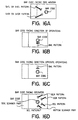
- FIGS. 16A-16D are diagrams illustrating the relationships between the bar code and the scanning pattern which scans the bar code for the four cases indicated above for FIG. 15 in accordance with embodiments of the present invention.
- FIG. 16A is a diagram illustrating the case when the bar code faces the side window 14.
- the bar code is scanned by the SHTR pattern, the SHDR pattern, the SHTL pattern or the SHDL pattern which are emitted from the side window 14.
- SHTR and SHDR, SHTL and SHDL which delineate virtually the same scanning locus, are not indicated as split in the figure.
- FIG. 16B is a diagram illustrating the case in which the bar code is facing the direction in which the product is moved.
- the bar code is scanned by the BML pattern which is emitted from the bottom window 3 facing the direction in which the product is moved.
- FIG. 16C is a diagram illustrating the case in which the bar code faces the direction opposite to that in which the product is moved.
- the bar code is scanned by the BMR pattern which is emitted from the bottom window 3.
- FIG. 16D is a diagram illustrating the case in which the bar code faces the operator.
- the bar code is not scanned by the scanning pattern emitted from the side window 14. Instead, the bar code is scanned by each of the patterns in BOR, BCR, BCL and BOL which are emitted from the bottom window 3 toward the side window 14.
- the BVR (BVL) pattern which delineates a scanning locus which is nearly vertical to the bottom window 14
- BOL BOR
- the BVR pattern which delineates a scanning locus which is nearly parallel to the bottom window 14
- these scanning patterns delineate different scanning loci, they scan the bar code under virtually the same conditions. Therefore, the same bar code can be read even if the bar code is vertical to the bottom window 14 and even if the bar code is horizontal to the bottom window 14.
- the bottom scanner part 1 As a result, in accordance with preferred embodiments of the present invention, complete 360° reading is provided even if the bar code is positioned vertically to the bottom window 14 and even if the bar code is positioned horizontally to the bottom window 14. It is also possible to make the bottom scanner part 1 thinner than the prior art multi-head scanner. Specifically, the thickness of the bottom scanner part 1 can be made so that it is 90 mm or less.
- scanning lines which scan a virtual flat surface which is nearly parallel to the side window 3 in the reading area can be generated from the bottom scanning part 1.
- the polygon mirror 6 is disposed on the upper part of the body of the side part 4, and the mirror which is used to generate part of the horizontal scanning line inside the body of the bottom part 1 is shared. Therefore, space inside the bottom part 1 is used effectively.
- two or more different scanning patterns comprising a horizontal pattern and a vertical pattern share the same two pattern mirrors in the optical path which extends to the reading opening (window) from the polygon mirror 6.
- a bar code reader with this type of configuration did not exist in the prior art.
- lengthening the distance from the polygon mirror 6 to the body of the bottom part 1 is extremely effective and advantageous in generating scanning lines with a scanning line length which is longer than at the same scanning angle. Furthermore, this configuration is also extremely useful in that it maintains a space inside the bottom pan 1 and makes it possible to increase the area of the pattern mirror or the number of pattern mirrors used.
- the pattern mirror used in prior art bar code readers to generate scanning lines which scan the virtual plane surface vertically cannot be assured the space needed to accommodate and place the pattern mirror inside the body part.
- the prior art bar code readers cannot achieve the scanning lines which vertically scan the virtual plane surface in accordance with the preferred embodiments of the present invention because the light beams of the prior art bar code readers are incident to the prior art polygon mirror from a single direction.
- the polygon mirror 6 has four reflecting surfaces (facets).
- the polygon mirror 6 is not limited to four (4) reflecting surfaces, and may have, for example, three (3) reflecting surfaces or five (5) or more reflecting surfaces.
- the scanning angle can be 180°.
- the scanning angle can be 240°.
- the scanning angle is a priority, the fewer the reflecting surfaces the better the result.
- scanning lines can be generated with a proportionately larger scanning line length when compared with the same optical path length.
- the number of scanning lines which can be generated with a single scanning declines. For example, when a polygon mirror 6 having three reflecting surfaces is used, three scanning lines are generated, while four scanning lines can be generated when a polygon mirror 6 having four reflecting surfaces is used.
- the scanning angle is smaller than a polygon mirror 6 with three surfaces so that a proportionately longer scanning line optical pat is required to obtain scanning lines with the same length.
- the polygon mirror 6 is set in place near the top of the body of the side part 4 so that the distance between the polygon mirror 6 and the bottom part 1 can be increased and the length of the optical path lengthened accordingly. As a result, in accordance with preferred embodiments of the present invention, scanning lines with a sufficient scanning line length can be obtained, even if a four-surface polygon mirror 6 having a small scanning angle is used.
- the scanning angle is shortened even further.
- the polygon mirror 6 is suitable for use if an optical path is obtained which is longer than the device with a polygon mirror 6 having four reflecting surfaces.
- scanning patterns having two pattern mirrors in common are used only in the bottom part 1.
- scanning patterns having two pattern mirrors in common may be used for the side pattern mirrors as well.
- different scanning patterns with three or more pattern mirrors in common may also be used.
- the device includes a speaker 15 which emits a sound indicating whether or not the bar code has been read and which is located on the top of the body of the side part 4.
- Prior art multi-head scanners have speakers which are located near the bottom of the side of the device. Nevertheless, in accordance with the prior art device, the side of the device is embedded in the counter so that the speaker is covered by the counter. As a result, the prior art device has problems in that it is difficult for the operator to confirm the sound indicating whether or not the bar code had been read. For example, since the area around supermarket checkout counters is rather noisy, the volume of the sound coming from the speaker has to be high. Therefore, it is impossible for the prior art speaker to emit sufficient volume because it is hidden away beneath the counter. Although the volume of the speaker can be increased by increasing the size of the speaker, prior art speakers which are mounted on multi-head scanners are not large enough, so that this manner of attacking the problem is not very effective.
- the speaker in accordance with the preferred embodiments of the present invention is attached to the front of the top of the body of the side part 4, a sound which has sufficiently high volume for the operator to tell whether or not the bar code has been read can be emitted despite a small diameter of the speaker. Furthermore, since there is also directivity in the direction in which the sound is transmitted, attaching the speaker to the front of the device rather than to the side is effective when sound transmission is taken into consideration.
- the pattern mirrors are placed wherever there is sufficient space.
- pattern mirrors are disposed both on the top and on the side of the body of the side part.
- priority is given to the placement of the pattern mirrors and other optical parts. Parts which do not particularly affect the speaker and the readout itself are attached as an afterthought in an open space after the optical parts are set in place. Therefore, in prior art multi-head scanners, speakers are attached on the side of the body of the device and underneath the counter.
- the polygon mirror 6 is disposed on the top of the body of the side part 4, and the rotation axis is disposed so that it is nearly horizontal in the device.
- optical parts cannot be disposed at positions which close off the optical path of the light which is incident to or incident from the polygon mirror 6.
- the pattern mirror is not disposed at the center of the side part 4, and, more particularly, the pattern mirror is not disposed near the top of the side part 4.
- the speaker 15 is disposed in a space where there is no pattern mirror and is near the top of the body of the side part 4. This is a secondary effect of the placing of the polygon mirror 6 in accordance with the present invention. The same holds true even for devices which use buzzers and the like instead of speakers.
- the speaker 15 when the speaker 15 is placed on the top of the body of the side part 4 there is a greater degree of freedom in disposing the pattern mirror and other optical parts inside the bottom part 1.
- the polygon mirror 6 and other scanning means need not be parallel to the surface of the bottom part 1. Rather, it is possible to increase the extent to which the optical pans can be disposed if scanning light is emitted (reflected) downward. Accordingly, the rotation axis may alternatively be vertical to the surface of the bottom part 1 as a result of the shape of the polygon mirror 6.
- the scanning device need not be placed near the top end of the body of the side part 4 if accommodation of the scanning device inside the body of the side part 4 is taken into consideration independently.
- the preferred embodiments of the present invention do not preclude the possibility of placing the scanning device near the bottom of the body of the side part 4 to fit the design.
- an effective reflecting surface faces upward and the scanning device may emit scanning light upwards.
- diffraction lattices may be used in addition to mirrors.
- the diffraction lattices may be the reflective type or the permeation type.
- the light beams from the light source need not be emitted vertically to the surface of the bottom part 1.
- light beams are emitted upward vertically to the surface of the bottom part 1 out of consideration for the placement of the pattern mirrors.
- the light beams need not be emitted vertically to the surface of the bottom part 1, and the light beams may be incident from the side as long as there are no problems with the disposition of the pattern mirrors.
- FIGS. 17-19 are diagrams illustrating an internal view of a bar code reader in accordance with a second embodiment of the present invention. More particularly, FIG. 17 is an internal side view, FIG. 18 is an internal upper view, and FIG. 19 is an internal frontal view of the bar code reader in accordance with the second embodiment of the present invention. Elements shown in FIGS. 17-19 which are the same as or similar to elements described above with reference to the first embodiment of the invention are referred to with like reference numerals.
- the device shown in FIGS. 17-19 has virtually the same outward appearance as the device shown in FIGS. 1-3.
- a primary difference between the device shown in FIGS. 1-3 and the device shown in FIGS. 17-19 is found in the disposition of the optical parts inside the device and the outgoing scanning pattern.
- the differences between the device shown in FIGS. 17-19 and the device shown in FIGS. 1-3 will now be discussed in detail below.
- the polygon mirror 6 shown in FIGS. 17-19 is positioned on top of the body of the side part 4.
- the polygon mirror 6 is the same as the polygon mirror 6 shown in FIGS. 1-3 in that the polygon mirror 6 has four reflective surfaces.
- the polygon mirror 6 shown in FIGS. 17-19 has a rotation axis which faces slightly upward toward the surface on which the product is slid.
- the rotation axis preferably faces upward at an angle of approximately 5°. Therefore, the scanning light generated by the polygon mirror 6 is emitted toward the side of the bottom part 1, in contrast to the device shown in FIGS. 1-3.
- the light source unit 5 of the device is disposed on the left side facing the side window 14 on top of the body of the side part 4.
- the light source 5 in accordance with the second embodiment of the invention emits laser light toward the bottom of the device.
- a small mirror 16 (FIG. 18) is placed below the polygon mirror 6 so that the laser light emitted from the light source 5 is incident to the polygon mirror 6.
- the small mirror 16 makes it possible for the laser light to be incident directly from the bottom toward the polygon mirror 6.
- the reflective light from the bar code is converged by a Fresnel lens 17 and is directed to a light detector 8 by a mirror 18 which is placed on the bottom of the side part 4.
- the main PCB 10 on which the light detector 8 is mounted is disposed on the bottom of the device.
- the surface which receives light for light detection faces the left-hand side of FIGS. 17-19.
- the light detector 8 in accordance with the second embodiment of the invention is placed on the bottom of the device so that the thickness of the device at the position corresponding to the bottom of the side part 4 at the bottom part 1 is somewhat greater than the thickness of the other end (right hand side in FIG. 17) of the bottom part 1.
- the portion having somewhat greater thickness is located at somewhat of a distance from the operator, enough space is provided for the operator's knees.
- the light source 5 is provided in the upper part of the side part 4, and not in the lower left hand side of the side part 4, as in FIG. 1.
- the space in the upper and lower parts of the bottom pan 1 provided with the main PCB 10 in FIG. 17 is wider than the same space in the device shown in FIG. 1.
- the wider space in this area is advantageous in that the area of the pattern mirror (BMR2, BML2 and the like) located at this position can be made larger, and the light reflected from the bar code can be converged even more than by using the device shown in FIG. 1.
- the laser light which is emitted downward from the light source 5 is reflected upward by the small mirror 16 placed between the polygon mirror 6 and the Fresnel lens 17 and is incident on the polygon mirror 6.
- the laser light is then scanned by the polygon mirror 6 and scanning light is generated.
- the scanning light generated from the polygon mirror 6 scans the pattern mirror in the following order SVL1 ⁇ SHR1 ⁇ BMR1 ⁇ BVR1 ⁇ BZ1 ⁇ BVL1 ⁇ BML1 ⁇ SHL1 ⁇ SVR1.
- the notation for the pattern mirror in accordance with the second embodiment is the same as was used in accordance with the first embodiment of the present invention.
- the scanning light generated by the polygon mirror 6 in accordance with the second embodiment of the invention scans a total of nine pattern mirrors.
- the bottom pattern mirror which generates the bottom pattern is made up of the following BMR1, BML1, BMR2, BML2, BMR3, BML3, BMR4, BML4, BZ1, BZ2, BHR, BHL.
- the main difference between the second embodiment and the first embodiment is in the number of pattern mirrors which are placed on the bottom of the bottom part 1.
- Each of the scanning patterns which make up the bottom pattern emitted from the bottom window 3 passes through the following paths.
- the scanning patterns use either the BMR4 or the BML4 pattern mirror in common.
- the BCL (BCR) and BOL (BOR) scanning patterns also use the BZ1 pattern mirror in common.
- the scanning patterns BOL (BOR) and BVL (BVR) use the pattern mirrors BHR (BHL) in common.
- the side pattern mirror which generates side patterns is made up of the following mirrors SVR1, SVL1, SVR2, SVL2, SVR3, SVL3, SHR1, SHL1, SHTR2, SHTL2, SHTR3, SHTL3, SHDR2, SHDL2, SHDR3, SHDL3, SHD4.
- the device in accordance with the second embodiment of the invention is particularly characteristic in that a single pattern mirror SHD4 is placed at the back of the body of the side part 4.
- Each of the scanning patterns which make up the side pattern is emitted from the side window 14 passing through the following paths.
- the paths SHTR (SHTL) and SHDR (SHDL) use SHR1 (SHL1) in common.
- 360° reading can be performed even if the bar code is vertical or horizontal to the bottom window 3.
- FIGS. 20A and 20B are diagrams showing the bottom pattern and side pattern on the bottom window 3 and side window 14 surfaces, respectively, in accordance with the second embodiment of the invention.
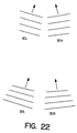
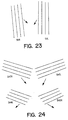
- FIG. 21 and FIG. 22 are diagrams showing the separation of the scanning patterns which make up the bottom pattern in accordance with the second embodiment of the present invention.
- FIG. 23 and FIG. 24 are diagrams showing the separation of the scanning patterns which make up the side pattern in accordance with the second embodiment of the present invention.
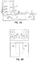
- FIG. 25 is an internal side view of the bar code reader in accordance with the second embodiment of the present invention.
- the pattern mirror which is placed on the bottom-most surface is indicated so that the manner in which it is disposed can be readily understood.
- FIG. 26 is an internal upper view of the bar code reader in accordance with the second embodiment of the invention which shows the manner in which the pattern mirror placed furthest in the rear in the figure is placed.
- a single light source 5 provides a single laser beam which is incident on the polygon mirror 6.
- the present invention is not limited to a single laser beam incident on the polygon mirror 6, and it is also completely appropriate to have multiple light sources or to have the laser light generated by a single light source which is split to provide multiple laser beams incident on the polygon mirror 6.
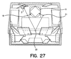
- FIG. 27 is an internal frontal view of a bar code reader in accordance with a third embodiment of the present invention.
- the optical scanner in accordance with the third embodiment is similar to the optical scanner described above with respect to the second embodiment and has an additional feature to the device shown in FIG. 17. More specifically, in the device shown in FIG. 27, the light beams emitted from the light source are split using a single light source using a beam splitter midway through. Part of the light which has been split is directly incident on the polygon mirror 6 and other part of the light which has been split is incident on the polygon mirror 6 from the opposite direction via a mirror 20 and a mirror 21.
- the respective plurality of laser beams are made to correspond respectively to the left and the right of the device. More particularly, some of the laser beams can be made to correspond to the scanning light which is emitted from the right hand side of the device while the rest of the laser beams are made to correspond to the scanning light which is emitted from the left hand side of the device.
- the device in accordance with the third embodiment of the present invention has a polygon mirror 6 with a large number of reflecting surfaces and is advantageous when the scanning angle for each surface is small.
- the device shown in FIGS. 1-3 in accordance with the first embodiment may be modified by setting in place a plurality of light sources and making the laser light incident on the polygon mirror 6 from these light sources respectively.
- one method of placing the light source involves placing two light sources so that they are symmetrical on the left and right to the centerline of the bar code reader. These light sources respectively emit laser light upwards.
- the laser light from different directions is incident on the polygon mirror 6.
- the light reflected from the bar code is incident on the device as it skirts the light shaft of the scanning light which itself scans the respective bar codes.
- multiple devices concave mirrors which converge the light reflected from the bar code must be set in place on the optical path of the laser light emitted from the respective light sources. Accordingly, as many light detectors as there are light sources are set in place.
- the length of the optical path may be made as long as possible. More specifically, the number of pattern mirrors which reflect the scanned light can be increased over the prior art device.
- the scanning patterns other than SVR and SVL are reflected by a minimum of three pattern mirrors.
- the BMR and BML patterns in particular are first reflected by four pattern mirrors and are then emitted from the bottom window 3.
- all of the scanning patterns are first reflected by three or more pattern mirrors and then emitted from a respective window.
- the four scanning patterns BMR, BML, SHDR and SHDL are first reflected by all four pattern mirrors and are then emitted from the corresponding windows.
- the prior art bar code readers do not contemplate using three or more pattern mirrors to reflect light of the scanning pattern, to generate scanning lines and to ensure the length of the optical path in the manner of the present invention. Further, the prior art does not contemplate a device in which scanning lines are emitted via four or more pattern mirrors.
- the polygon mirror and other scanning means are arranged and constructed so that the rotation axis is nearly parallel to the surface of the product which slides along and are accommodated inside the body of the side part.
- This arrangement and construction of the polygon mirror and other scanning devices makes it possible to ensure a space inside the bottom part and to increase the degree of freedom to which the pattern mirrors can be placed.
- the area of the pattern mirror is widened and the converging efficiency of the reflected light from the bar code can be increased.
- the scanning device is set on the top of the body of the side part so that a space can be left at the position where the side part and the bottom part intersect, and the degree of freedom with which the optical parts can be placed can be increased.
- the light source is arranged in the side part and light beams are emitted vertically to the surface of the product which is slid.
- a light detector which receives light from the bar code is placed inside the body of the side part and the light-receiving surface is pointed downward.
- a substrate on which the light detector is mounted is placed so that it is nearly parallel to the rear surface of the body of the side part.
- the thickness of the bottom part can be reduced. Moreover, in accordance with embodiments of the invention, a thickness of 90 mm can be realized, which is impossible with the prior art multi-head scanner.
- a scanning pattern is emitted.
- the optical path from the light source to the reading position can be lengthened without increasing the size of the device itself. This is extremely effective and advantageous m generating scanning lines with the required scanning line length when the scanning angle is small.
- two or more pattern mirrors can be used commonly with different scanning patterns, thus avoiding placing a unique pattern mirror for each respective scanning pattern which results in making the device ever larger. Further, if a unique pattern mirror is used for each respective scanning pattern and if the device is not made larger, it will be subject to the limitations of pattern mirror placement, and it will no longer be possible to obtain the desired scanning pattern. However, in accordance with embodiments of the present invention, two or more pattern mirrors are used in common with different scanning patterns so that the number of pattern mirrors is reduced. As a result, the limitations on placement of the pattern mirror inside the body are reduced as compared to the prior art device and the effective surface of the pattern mirror can be increased.
- scanning patterns which delineate scanning loci in different directions are reflected by a common pattern mirror and then generated, just like a scanning pattern which delineates a scanning locus vertically and a scanning locus horizontally.
- the scanning direction of the mutual scanning patterns can be made to virtually coincide.
- 360° reading can be realized in a multi-head scanner regardless of the orientation of the bar code.
- a bar code by emitting scanning patterns which delineate different scanning patterns from the same direction, a bar code can be read regardless of the angle and the orientation of the bar code vis-a-vis the surface of the counter and the bar code reading performance can be upgraded even if a multi-head scanner is not used.
Landscapes
- Physics & Mathematics (AREA)
- Engineering & Computer Science (AREA)
- Electromagnetism (AREA)
- General Physics & Mathematics (AREA)
- Artificial Intelligence (AREA)
- Toxicology (AREA)
- General Health & Medical Sciences (AREA)
- Computer Vision & Pattern Recognition (AREA)
- Health & Medical Sciences (AREA)
- Theoretical Computer Science (AREA)
- Optics & Photonics (AREA)
- Mechanical Optical Scanning Systems (AREA)
- Facsimile Scanning Arrangements (AREA)
Priority Applications (1)
| Application Number | Priority Date | Filing Date | Title |
|---|---|---|---|
| EP02017773A EP1260932A1 (fr) | 1998-10-21 | 1999-10-20 | Système de balayage optique, lecteur de code, lecteur de code à barres, à degré de liberté élevé du placement des pièces optiques |
Applications Claiming Priority (2)
| Application Number | Priority Date | Filing Date | Title |
|---|---|---|---|
| JP29962198 | 1998-10-21 | ||
| JP29962198A JP3881792B2 (ja) | 1998-10-21 | 1998-10-21 | 光走査装置、コード読取装置およびバーコード読取装置 |
Related Child Applications (1)
| Application Number | Title | Priority Date | Filing Date |
|---|---|---|---|
| EP02017773A Division EP1260932A1 (fr) | 1998-10-21 | 1999-10-20 | Système de balayage optique, lecteur de code, lecteur de code à barres, à degré de liberté élevé du placement des pièces optiques |
Publications (3)
| Publication Number | Publication Date |
|---|---|
| EP0996077A2 true EP0996077A2 (fr) | 2000-04-26 |
| EP0996077A3 EP0996077A3 (fr) | 2000-08-16 |
| EP0996077B1 EP0996077B1 (fr) | 2007-09-26 |
Family
ID=17874989
Family Applications (2)
| Application Number | Title | Priority Date | Filing Date |
|---|---|---|---|
| EP99120078A Expired - Lifetime EP0996077B1 (fr) | 1998-10-21 | 1999-10-20 | Système de balayage optique, lecteur de code, lecteur de code à barres, à degrée de liberté élevé du placement des pièces optiques |
| EP02017773A Withdrawn EP1260932A1 (fr) | 1998-10-21 | 1999-10-20 | Système de balayage optique, lecteur de code, lecteur de code à barres, à degré de liberté élevé du placement des pièces optiques |
Family Applications After (1)
| Application Number | Title | Priority Date | Filing Date |
|---|---|---|---|
| EP02017773A Withdrawn EP1260932A1 (fr) | 1998-10-21 | 1999-10-20 | Système de balayage optique, lecteur de code, lecteur de code à barres, à degré de liberté élevé du placement des pièces optiques |
Country Status (6)
| Country | Link |
|---|---|
| US (1) | US6631844B1 (fr) |
| EP (2) | EP0996077B1 (fr) |
| JP (1) | JP3881792B2 (fr) |
| KR (1) | KR100572604B1 (fr) |
| CN (1) | CN1237471C (fr) |
| DE (1) | DE69937179T2 (fr) |
Families Citing this family (18)
| Publication number | Priority date | Publication date | Assignee | Title |
|---|---|---|---|---|
| US7051922B2 (en) | 1994-08-17 | 2006-05-30 | Metrologic Instruments, Inc. | Compact bioptical laser scanning system |
| TW550936B (en) * | 2001-12-31 | 2003-09-01 | Veutron Corp | Optical path layout of image capturing system and the achieving method thereof |
| US7773149B2 (en) * | 2002-07-16 | 2010-08-10 | Yin-Chun Huang | Layout of the optical path in the image capturing system and the method for forming the same |
| US7111785B2 (en) * | 2003-06-05 | 2006-09-26 | Symbol Technologies, Inc. | Compact, omni-directional scan pattern generator and method in a reader for electro-optically reading indicia |
| US6866197B1 (en) * | 2003-10-17 | 2005-03-15 | Ncr Corporation | Optical scanner having enhanced item side coverage |
| US7137560B2 (en) * | 2004-11-30 | 2006-11-21 | Ncr Corporation | Optical scanner |
| JP4388116B2 (ja) * | 2007-11-26 | 2009-12-24 | 東芝テック株式会社 | バーコード読取装置 |
| CN102047270A (zh) * | 2008-05-28 | 2011-05-04 | 得利捷扫描集团有限公司 | 用于编码信息读取器的充电支架和包括该充电支架的读取系统 |
| US8919651B2 (en) | 2010-07-23 | 2014-12-30 | Datalogic ADC, Inc. | Data reader having compact arrangement |
| US9122939B2 (en) | 2010-09-16 | 2015-09-01 | Datalogic ADC, Inc. | System and method for reading optical codes on reflective surfaces while minimizing flicker perception of pulsed illumination |
| US8960548B2 (en) | 2012-06-08 | 2015-02-24 | Datalogic ADC, Inc. | Bioptic data reader with split vertical windows and speaker |
| US9016578B2 (en) * | 2013-05-14 | 2015-04-28 | Symbol Technologies, Inc. | Apparatus for and method of electro-optically reading a target in the presence of ambient light by suppressing the ambient light |
| USD723560S1 (en) * | 2013-07-03 | 2015-03-03 | Hand Held Products, Inc. | Scanner |
| USD730901S1 (en) * | 2014-06-24 | 2015-06-02 | Hand Held Products, Inc. | In-counter barcode scanner |
| US9594936B1 (en) | 2015-11-04 | 2017-03-14 | Datalogic Usa, Inc. | System and method for improved reading of data from reflective surfaces of electronic devices |
| CN105956507A (zh) * | 2016-05-12 | 2016-09-21 | 刘青建 | 一种底照式双头扫描装置 |
| EP3312760B8 (fr) * | 2016-10-18 | 2020-04-22 | Leuze electronic GmbH + Co KG | Capteur optique |
| CN107704792A (zh) * | 2017-08-30 | 2018-02-16 | 合肥新文远信息技术有限公司 | 一种防伪二维码读取器 |
Citations (7)
| Publication number | Priority date | Publication date | Assignee | Title |
|---|---|---|---|---|
| US4093865A (en) * | 1977-04-29 | 1978-06-06 | National Semiconductor Corporation | Code symbol scanner using a double X bar pattern |
| WO1994001835A1 (fr) * | 1992-07-14 | 1994-01-20 | Spectra-Physics Scanning Systems, Inc. | Systeme de balayage multiplans pour la lecture de donnees |
| EP0772147A2 (fr) * | 1995-10-30 | 1997-05-07 | Ncr International Inc. | Balayeur optique à couverture améliorée des cÔtés des objets |
| DE19545137A1 (de) * | 1995-12-04 | 1997-06-05 | Cristoffer Stratmann | System zur Registrierung und Abrechnung von Waren in Selbstbedienungsgeschäften |
| EP0779591A2 (fr) * | 1995-12-14 | 1997-06-18 | Fujitsu Limited | Lecteur de codes à barres |
| EP0811958A2 (fr) * | 1996-06-05 | 1997-12-10 | NCR International, Inc. | Dispositif et méthodes d'enregistrement en libre-service d'articles-en-sortie |
| US5825010A (en) * | 1994-11-21 | 1998-10-20 | Symbol Technologies, Inc. | Bar code scanner positioning |
Family Cites Families (43)
| Publication number | Priority date | Publication date | Assignee | Title |
|---|---|---|---|---|
| BE622375A (fr) | 1961-09-13 | |||
| GB1280678A (en) | 1968-06-27 | 1972-07-05 | Rca Corp | Article designator |
| US3812325A (en) | 1970-08-18 | 1974-05-21 | Chesapeake & Ohio Railway | Means for reading and interpreting color-coded identification labels |
| US3728677A (en) | 1971-05-10 | 1973-04-17 | Stanford Research Inst | Rotation-independent reading of rectangular insignia |
| US3818444A (en) | 1972-06-29 | 1974-06-18 | Pitney Bowes Inc | Optical bar code reading method and apparatus having an x scan pattern |
| US3916158A (en) | 1974-01-21 | 1975-10-28 | Pitney Bowes Inc | Optical scanner and method for producing a scanning pattern |
| US3958104A (en) | 1974-03-06 | 1976-05-18 | Servo Corporation Of America | Multiplexed optical scanner system |
| US3947816A (en) | 1974-07-01 | 1976-03-30 | International Business Machines Corporation | Omnidirectional optical scanning apparatus |
| NL7713933A (en) | 1977-12-15 | 1979-06-19 | Sweda International Inc | Optical scanning system with backward reflection - uses multiple cross principle with parallel lines as scanning tracks excited at speed of rotating element |
| DE2757235C2 (de) | 1977-12-22 | 1983-02-17 | Sweda International, Inc., 07058 Pine Brook, N.J. | Optisch-mechanische Abtastvorrichtung mit einem rotierenden Spiegelrad |
| US4224509A (en) | 1978-10-19 | 1980-09-23 | Ncr Corporation | Holographic scanning system |
| JPS56164312A (en) | 1980-05-22 | 1981-12-17 | Konishiroku Photo Ind Co Ltd | Optical deflecting device |
| US4587407A (en) | 1983-06-20 | 1986-05-06 | Westinghouse Electric Corp. | Scanning system for bar code labels affixed to rods |
| JPS60238811A (ja) | 1984-05-11 | 1985-11-27 | Fuji Photo Film Co Ltd | 光ビ−ム走査装置 |
| JPS61200524A (ja) | 1985-03-01 | 1986-09-05 | Fuji Photo Film Co Ltd | 光走査装置 |
| US4753498A (en) | 1985-03-22 | 1988-06-28 | Tokyo Kogaku Kikai Kabushiki Kaisha | Optical reader |
| JPS61233876A (ja) | 1985-04-08 | 1986-10-18 | Sumitomo Electric Ind Ltd | 光学式読取装置 |
| JPS61238811A (ja) | 1985-04-16 | 1986-10-24 | Nippon Oil & Fats Co Ltd | 非水系重合体分散液の製造法 |
| US4652732A (en) | 1985-09-17 | 1987-03-24 | National Semiconductor Corporation | Low-profile bar code scanner |
| US4795224A (en) | 1986-10-06 | 1989-01-03 | Katsuchika Goto | Optical scanning pattern generator |
| US4816661A (en) | 1986-12-22 | 1989-03-28 | Symbol Technologies, Inc. | Scan pattern generators for bar code symbol readers |
| JPS63311320A (ja) | 1987-06-15 | 1988-12-20 | Canon Inc | 光走査装置 |
| JPH0193715A (ja) | 1987-10-05 | 1989-04-12 | Minolta Camera Co Ltd | 回転走査体 |
| JP2737143B2 (ja) | 1988-03-08 | 1998-04-08 | 日本電気株式会社 | バーコード読取装置 |
| JPH0253194A (ja) | 1988-08-17 | 1990-02-22 | Syst Interijiensu Prod:Kk | 識別標識および読取装置 |
| US5293033A (en) * | 1988-09-20 | 1994-03-08 | Tokyo Electric Co., Ltd. | Optical reading apparatus |
| JP2732497B2 (ja) | 1988-09-21 | 1998-03-30 | 株式会社テック | 商品データ読取装置 |
| US4935609A (en) | 1988-12-15 | 1990-06-19 | Ncr Corporation | Composite lens for a hand-held bar code label reader |
| JP2771593B2 (ja) | 1989-04-20 | 1998-07-02 | 富士通株式会社 | 光走査装置 |
| US4971410A (en) | 1989-07-27 | 1990-11-20 | Ncr Corporation | Scanning and collection system for a compact laser |
| US5128520A (en) * | 1989-08-11 | 1992-07-07 | Spectra-Physics, Inc. | Scanner with coupon validation |
| US5019694A (en) | 1989-09-29 | 1991-05-28 | Ncr Corporation | Overhead scanning terminal |
| US5268565A (en) | 1989-10-16 | 1993-12-07 | Fujitsu Limited | Compact type bar code reader |
| US5206491A (en) * | 1990-03-02 | 1993-04-27 | Fujitsu Limited | Plural beam, plural window multi-direction bar code reading device |
| US5073702A (en) | 1990-03-26 | 1991-12-17 | Ncr Corporation | Multiple beam bar code scanner |
| US5491328A (en) * | 1991-09-24 | 1996-02-13 | Spectra-Physics Scanning Systems, Inc. | Checkout counter scanner having multiple scanning surfaces |
| US5229588A (en) | 1991-09-30 | 1993-07-20 | Ncr Corporation | Dual aperture optical scanner |
| JP2789282B2 (ja) | 1992-07-10 | 1998-08-20 | 富士通株式会社 | 光学式マーク読取装置 |
| US5475207A (en) | 1992-07-14 | 1995-12-12 | Spectra-Physics Scanning Systems, Inc. | Multiple plane scanning system for data reading applications |
| US5834708A (en) * | 1995-06-08 | 1998-11-10 | Spectra-Physics Scanning Systems, Inc. | Multiple plane weigh platter for multiple plane scanning systems |
| US5886336A (en) * | 1996-12-12 | 1999-03-23 | Ncr Corporation | Multiside coverage optical scanner |
| JP3628867B2 (ja) * | 1997-04-24 | 2005-03-16 | 東芝テック株式会社 | バーコード読取装置 |
| US5975417A (en) * | 1997-12-19 | 1999-11-02 | Ncr Corporation | Convertible barcode scanner |
-
1998
- 1998-10-21 JP JP29962198A patent/JP3881792B2/ja not_active Expired - Fee Related
-
1999
- 1999-10-18 KR KR1019990045076A patent/KR100572604B1/ko not_active IP Right Cessation
- 1999-10-20 EP EP99120078A patent/EP0996077B1/fr not_active Expired - Lifetime
- 1999-10-20 DE DE69937179T patent/DE69937179T2/de not_active Expired - Lifetime
- 1999-10-20 EP EP02017773A patent/EP1260932A1/fr not_active Withdrawn
- 1999-10-21 CN CNB991231198A patent/CN1237471C/zh not_active Expired - Fee Related
- 1999-10-21 US US09/422,268 patent/US6631844B1/en not_active Expired - Lifetime
Patent Citations (7)
| Publication number | Priority date | Publication date | Assignee | Title |
|---|---|---|---|---|
| US4093865A (en) * | 1977-04-29 | 1978-06-06 | National Semiconductor Corporation | Code symbol scanner using a double X bar pattern |
| WO1994001835A1 (fr) * | 1992-07-14 | 1994-01-20 | Spectra-Physics Scanning Systems, Inc. | Systeme de balayage multiplans pour la lecture de donnees |
| US5825010A (en) * | 1994-11-21 | 1998-10-20 | Symbol Technologies, Inc. | Bar code scanner positioning |
| EP0772147A2 (fr) * | 1995-10-30 | 1997-05-07 | Ncr International Inc. | Balayeur optique à couverture améliorée des cÔtés des objets |
| DE19545137A1 (de) * | 1995-12-04 | 1997-06-05 | Cristoffer Stratmann | System zur Registrierung und Abrechnung von Waren in Selbstbedienungsgeschäften |
| EP0779591A2 (fr) * | 1995-12-14 | 1997-06-18 | Fujitsu Limited | Lecteur de codes à barres |
| EP0811958A2 (fr) * | 1996-06-05 | 1997-12-10 | NCR International, Inc. | Dispositif et méthodes d'enregistrement en libre-service d'articles-en-sortie |
Also Published As
| Publication number | Publication date |
|---|---|
| KR20000029150A (ko) | 2000-05-25 |
| KR100572604B1 (ko) | 2006-04-24 |
| CN1237471C (zh) | 2006-01-18 |
| CN1251455A (zh) | 2000-04-26 |
| US6631844B1 (en) | 2003-10-14 |
| JP3881792B2 (ja) | 2007-02-14 |
| EP0996077A3 (fr) | 2000-08-16 |
| DE69937179D1 (de) | 2007-11-08 |
| DE69937179T2 (de) | 2008-01-10 |
| JP2000121984A (ja) | 2000-04-28 |
| EP0996077B1 (fr) | 2007-09-26 |
| EP1260932A1 (fr) | 2002-11-27 |
Similar Documents
| Publication | Publication Date | Title |
|---|---|---|
| US6631844B1 (en) | Optical scanner, code reader and bar code reader having increased degree of freedom in placement of optical parts | |
| US6568598B1 (en) | Multiple plane scanning system for data reading applications | |
| US5945658A (en) | Automatically selectable range laser scanner | |
| US6854655B2 (en) | Two window optical scanner | |
| US6708883B2 (en) | Apparatus and method for reading indicia using charge coupled device and scanning laser beam technology | |
| US6398112B1 (en) | Apparatus and method for reading indicia using charge coupled device and scanning laser beam technology | |
| US5479002A (en) | Bar code scanner with scanning beam and/or field of view adjustable about three mutually orthogonal axes | |
| EP0535905A1 (fr) | Dispositif d'exploration optique | |
| US5117098A (en) | Multi-position trigger for control over aiming and symbol reading in a portable laser diode scanning head | |
| EP0752680B1 (fr) | Scanner optique avec des éléments optiques avec deux surfaces pour deux rayons d'action | |
| EP0449490A1 (fr) | Explorateur optique | |
| US5142131A (en) | Hand-held bar code reader | |
| EP1039409A3 (fr) | Module de balayage rétro-réfléchissant pour lecteurs électro-optiques | |
| JPH03179579A (ja) | 電気光学的記号読み取り装置 | |
| EP0378198A2 (fr) | Méthode et appareil pour lire des codes à barres | |
| US7552874B2 (en) | Optical scanner | |
| EP0414452B1 (fr) | Lecteur de code-barre portatif | |
| JPH0823629B2 (ja) | 光学読取装置 | |
| US5043563A (en) | Portable overhead bar code scanner | |
| US6273337B1 (en) | Tilted offset barcode scanner | |
| JP4187296B2 (ja) | 光学的情報読み取り装置 | |
| EP0532220B1 (fr) | Lecteur de code barre et sa manière de fonction | |
| JP3791493B2 (ja) | 光走査装置、コード読取装置およびバーコード読取装置 | |
| EP1261934A1 (fr) | Lecteur de code-barres a formats multiples | |
| JPH117489A (ja) | バーコード読み取り装置 |
Legal Events
| Date | Code | Title | Description |
|---|---|---|---|
| PUAI | Public reference made under article 153(3) epc to a published international application that has entered the european phase |
Free format text: ORIGINAL CODE: 0009012 |
|
| AK | Designated contracting states |
Kind code of ref document: A2 Designated state(s): DE FR GB |
|
| AX | Request for extension of the european patent |
Free format text: AL;LT;LV;MK;RO;SI |
|
| PUAL | Search report despatched |
Free format text: ORIGINAL CODE: 0009013 |
|
| RIC1 | Information provided on ipc code assigned before grant |
Free format text: 7G 06K 7/10 A, 7G 07G 1/00 B |
|
| AK | Designated contracting states |
Kind code of ref document: A3 Designated state(s): AT BE CH CY DE DK ES FI FR GB GR IE IT LI LU MC NL PT SE |
|
| AX | Request for extension of the european patent |
Free format text: AL;LT;LV;MK;RO;SI |
|
| 17P | Request for examination filed |
Effective date: 20001204 |
|
| AKX | Designation fees paid |
Free format text: DE FR GB |
|
| 17Q | First examination report despatched |
Effective date: 20060113 |
|
| GRAP | Despatch of communication of intention to grant a patent |
Free format text: ORIGINAL CODE: EPIDOSNIGR1 |
|
| GRAS | Grant fee paid |
Free format text: ORIGINAL CODE: EPIDOSNIGR3 |
|
| GRAA | (expected) grant |
Free format text: ORIGINAL CODE: 0009210 |
|
| AK | Designated contracting states |
Kind code of ref document: B1 Designated state(s): DE FR GB |
|
| REG | Reference to a national code |
Ref country code: GB Ref legal event code: FG4D |
|
| REF | Corresponds to: |
Ref document number: 69937179 Country of ref document: DE Date of ref document: 20071108 Kind code of ref document: P |
|
| ET | Fr: translation filed | ||
| PLBE | No opposition filed within time limit |
Free format text: ORIGINAL CODE: 0009261 |
|
| STAA | Information on the status of an ep patent application or granted ep patent |
Free format text: STATUS: NO OPPOSITION FILED WITHIN TIME LIMIT |
|
| 26N | No opposition filed |
Effective date: 20080627 |
|
| PGFP | Annual fee paid to national office [announced via postgrant information from national office to epo] |
Ref country code: DE Payment date: 20091015 Year of fee payment: 11 |
|
| PGFP | Annual fee paid to national office [announced via postgrant information from national office to epo] |
Ref country code: GB Payment date: 20091014 Year of fee payment: 11 Ref country code: FR Payment date: 20091029 Year of fee payment: 11 |
|
| GBPC | Gb: european patent ceased through non-payment of renewal fee |
Effective date: 20101020 |
|
| PG25 | Lapsed in a contracting state [announced via postgrant information from national office to epo] |
Ref country code: FR Free format text: LAPSE BECAUSE OF NON-PAYMENT OF DUE FEES Effective date: 20101102 |
|
| REG | Reference to a national code |
Ref country code: FR Ref legal event code: ST Effective date: 20110630 |
|
| PG25 | Lapsed in a contracting state [announced via postgrant information from national office to epo] |
Ref country code: GB Free format text: LAPSE BECAUSE OF NON-PAYMENT OF DUE FEES Effective date: 20101020 |
|
| REG | Reference to a national code |
Ref country code: DE Ref legal event code: R119 Ref document number: 69937179 Country of ref document: DE Effective date: 20110502 |
|
| PG25 | Lapsed in a contracting state [announced via postgrant information from national office to epo] |
Ref country code: DE Free format text: LAPSE BECAUSE OF NON-PAYMENT OF DUE FEES Effective date: 20110502 |