EP0995668A1 - Hohlkammer-Leichtbauteil - Google Patents
Hohlkammer-Leichtbauteil Download PDFInfo
- Publication number
- EP0995668A1 EP0995668A1 EP99119917A EP99119917A EP0995668A1 EP 0995668 A1 EP0995668 A1 EP 0995668A1 EP 99119917 A EP99119917 A EP 99119917A EP 99119917 A EP99119917 A EP 99119917A EP 0995668 A1 EP0995668 A1 EP 0995668A1
- Authority
- EP
- European Patent Office
- Prior art keywords
- housing part
- plastic
- support structure
- cover plate
- component according
- Prior art date
- Legal status (The legal status is an assumption and is not a legal conclusion. Google has not performed a legal analysis and makes no representation as to the accuracy of the status listed.)
- Granted
Links
- 239000004033 plastic Substances 0.000 claims abstract description 69
- 229920003023 plastic Polymers 0.000 claims abstract description 69
- 239000000463 material Substances 0.000 claims abstract description 28
- 229910052751 metal Inorganic materials 0.000 claims abstract description 18
- 239000002184 metal Substances 0.000 claims abstract description 18
- 229920001169 thermoplastic Polymers 0.000 claims abstract description 11
- 239000004416 thermosoftening plastic Substances 0.000 claims abstract description 8
- 238000004519 manufacturing process Methods 0.000 claims abstract description 5
- 238000003466 welding Methods 0.000 claims description 32
- 238000000034 method Methods 0.000 claims description 20
- 238000001746 injection moulding Methods 0.000 claims description 12
- 239000002131 composite material Substances 0.000 claims description 11
- 229910000831 Steel Inorganic materials 0.000 claims description 10
- 239000010959 steel Substances 0.000 claims description 10
- 238000010276 construction Methods 0.000 claims description 8
- 238000004026 adhesive bonding Methods 0.000 claims description 7
- 239000004952 Polyamide Substances 0.000 claims description 5
- 239000004743 Polypropylene Substances 0.000 claims description 5
- 229910052782 aluminium Inorganic materials 0.000 claims description 5
- XAGFODPZIPBFFR-UHFFFAOYSA-N aluminium Chemical compound [Al] XAGFODPZIPBFFR-UHFFFAOYSA-N 0.000 claims description 5
- 238000002347 injection Methods 0.000 claims description 5
- 239000007924 injection Substances 0.000 claims description 5
- 229920002647 polyamide Polymers 0.000 claims description 5
- 229920001707 polybutylene terephthalate Polymers 0.000 claims description 5
- 229920001155 polypropylene Polymers 0.000 claims description 5
- 239000011324 bead Substances 0.000 claims description 4
- -1 polybutylene terephthalate Polymers 0.000 claims description 4
- FYYHWMGAXLPEAU-UHFFFAOYSA-N Magnesium Chemical compound [Mg] FYYHWMGAXLPEAU-UHFFFAOYSA-N 0.000 claims description 3
- 229920000122 acrylonitrile butadiene styrene Polymers 0.000 claims description 3
- 239000004676 acrylonitrile butadiene styrene Substances 0.000 claims description 3
- 239000011777 magnesium Substances 0.000 claims description 3
- 229910052749 magnesium Inorganic materials 0.000 claims description 3
- 229920000515 polycarbonate Polymers 0.000 claims description 3
- 239000004417 polycarbonate Substances 0.000 claims description 3
- 239000004793 Polystyrene Substances 0.000 claims description 2
- HCHKCACWOHOZIP-UHFFFAOYSA-N Zinc Chemical compound [Zn] HCHKCACWOHOZIP-UHFFFAOYSA-N 0.000 claims description 2
- 229920000728 polyester Polymers 0.000 claims description 2
- 229920002223 polystyrene Polymers 0.000 claims description 2
- 229920002635 polyurethane Polymers 0.000 claims description 2
- 239000004814 polyurethane Substances 0.000 claims description 2
- 239000012815 thermoplastic material Substances 0.000 claims description 2
- 229910052725 zinc Inorganic materials 0.000 claims description 2
- 239000011701 zinc Substances 0.000 claims description 2
- 238000004023 plastic welding Methods 0.000 claims 2
- 239000000853 adhesive Substances 0.000 claims 1
- 230000001070 adhesive effect Effects 0.000 claims 1
- 238000010521 absorption reaction Methods 0.000 description 2
- 238000005452 bending Methods 0.000 description 2
- 238000001125 extrusion Methods 0.000 description 2
- 238000000465 moulding Methods 0.000 description 2
- 238000007493 shaping process Methods 0.000 description 2
- 229920002430 Fibre-reinforced plastic Polymers 0.000 description 1
- 230000005540 biological transmission Effects 0.000 description 1
- 239000000969 carrier Substances 0.000 description 1
- 238000007765 extrusion coating Methods 0.000 description 1
- 239000011151 fibre-reinforced plastic Substances 0.000 description 1
- 239000003365 glass fiber Substances 0.000 description 1
- 239000003292 glue Substances 0.000 description 1
- 238000009434 installation Methods 0.000 description 1
- 239000007788 liquid Substances 0.000 description 1
- 239000000203 mixture Substances 0.000 description 1
- 230000002028 premature Effects 0.000 description 1
- 239000002990 reinforced plastic Substances 0.000 description 1
- 230000002787 reinforcement Effects 0.000 description 1
- 238000002604 ultrasonography Methods 0.000 description 1
Images







Classifications
-
- B—PERFORMING OPERATIONS; TRANSPORTING
- B62—LAND VEHICLES FOR TRAVELLING OTHERWISE THAN ON RAILS
- B62D—MOTOR VEHICLES; TRAILERS
- B62D29/00—Superstructures, understructures, or sub-units thereof, characterised by the material thereof
- B62D29/001—Superstructures, understructures, or sub-units thereof, characterised by the material thereof characterised by combining metal and synthetic material
-
- B—PERFORMING OPERATIONS; TRANSPORTING
- B29—WORKING OF PLASTICS; WORKING OF SUBSTANCES IN A PLASTIC STATE IN GENERAL
- B29C—SHAPING OR JOINING OF PLASTICS; SHAPING OF MATERIAL IN A PLASTIC STATE, NOT OTHERWISE PROVIDED FOR; AFTER-TREATMENT OF THE SHAPED PRODUCTS, e.g. REPAIRING
- B29C45/00—Injection moulding, i.e. forcing the required volume of moulding material through a nozzle into a closed mould; Apparatus therefor
- B29C45/14—Injection moulding, i.e. forcing the required volume of moulding material through a nozzle into a closed mould; Apparatus therefor incorporating preformed parts or layers, e.g. injection moulding around inserts or for coating articles
- B29C45/14467—Joining articles or parts of a single article
-
- B—PERFORMING OPERATIONS; TRANSPORTING
- B62—LAND VEHICLES FOR TRAVELLING OTHERWISE THAN ON RAILS
- B62D—MOTOR VEHICLES; TRAILERS
- B62D29/00—Superstructures, understructures, or sub-units thereof, characterised by the material thereof
- B62D29/001—Superstructures, understructures, or sub-units thereof, characterised by the material thereof characterised by combining metal and synthetic material
- B62D29/004—Superstructures, understructures, or sub-units thereof, characterised by the material thereof characterised by combining metal and synthetic material the metal being over-moulded by the synthetic material, e.g. in a mould
-
- B—PERFORMING OPERATIONS; TRANSPORTING
- B62—LAND VEHICLES FOR TRAVELLING OTHERWISE THAN ON RAILS
- B62D—MOTOR VEHICLES; TRAILERS
- B62D29/00—Superstructures, understructures, or sub-units thereof, characterised by the material thereof
- B62D29/04—Superstructures, understructures, or sub-units thereof, characterised by the material thereof predominantly of synthetic material
- B62D29/041—Understructures
-
- B—PERFORMING OPERATIONS; TRANSPORTING
- B29—WORKING OF PLASTICS; WORKING OF SUBSTANCES IN A PLASTIC STATE IN GENERAL
- B29C—SHAPING OR JOINING OF PLASTICS; SHAPING OF MATERIAL IN A PLASTIC STATE, NOT OTHERWISE PROVIDED FOR; AFTER-TREATMENT OF THE SHAPED PRODUCTS, e.g. REPAIRING
- B29C45/00—Injection moulding, i.e. forcing the required volume of moulding material through a nozzle into a closed mould; Apparatus therefor
- B29C45/14—Injection moulding, i.e. forcing the required volume of moulding material through a nozzle into a closed mould; Apparatus therefor incorporating preformed parts or layers, e.g. injection moulding around inserts or for coating articles
- B29C45/14336—Coating a portion of the article, e.g. the edge of the article
- B29C45/14344—Moulding in or through a hole in the article, e.g. outsert moulding
-
- B—PERFORMING OPERATIONS; TRANSPORTING
- B29—WORKING OF PLASTICS; WORKING OF SUBSTANCES IN A PLASTIC STATE IN GENERAL
- B29C—SHAPING OR JOINING OF PLASTICS; SHAPING OF MATERIAL IN A PLASTIC STATE, NOT OTHERWISE PROVIDED FOR; AFTER-TREATMENT OF THE SHAPED PRODUCTS, e.g. REPAIRING
- B29C65/00—Joining or sealing of preformed parts, e.g. welding of plastics materials; Apparatus therefor
- B29C65/02—Joining or sealing of preformed parts, e.g. welding of plastics materials; Apparatus therefor by heating, with or without pressure
- B29C65/08—Joining or sealing of preformed parts, e.g. welding of plastics materials; Apparatus therefor by heating, with or without pressure using ultrasonic vibrations
-
- B—PERFORMING OPERATIONS; TRANSPORTING
- B29—WORKING OF PLASTICS; WORKING OF SUBSTANCES IN A PLASTIC STATE IN GENERAL
- B29C—SHAPING OR JOINING OF PLASTICS; SHAPING OF MATERIAL IN A PLASTIC STATE, NOT OTHERWISE PROVIDED FOR; AFTER-TREATMENT OF THE SHAPED PRODUCTS, e.g. REPAIRING
- B29C65/00—Joining or sealing of preformed parts, e.g. welding of plastics materials; Apparatus therefor
- B29C65/56—Joining or sealing of preformed parts, e.g. welding of plastics materials; Apparatus therefor using mechanical means or mechanical connections, e.g. form-fits
- B29C65/562—Joining or sealing of preformed parts, e.g. welding of plastics materials; Apparatus therefor using mechanical means or mechanical connections, e.g. form-fits using extra joining elements, i.e. which are not integral with the parts to be joined
-
- B—PERFORMING OPERATIONS; TRANSPORTING
- B29—WORKING OF PLASTICS; WORKING OF SUBSTANCES IN A PLASTIC STATE IN GENERAL
- B29C—SHAPING OR JOINING OF PLASTICS; SHAPING OF MATERIAL IN A PLASTIC STATE, NOT OTHERWISE PROVIDED FOR; AFTER-TREATMENT OF THE SHAPED PRODUCTS, e.g. REPAIRING
- B29C65/00—Joining or sealing of preformed parts, e.g. welding of plastics materials; Apparatus therefor
- B29C65/56—Joining or sealing of preformed parts, e.g. welding of plastics materials; Apparatus therefor using mechanical means or mechanical connections, e.g. form-fits
- B29C65/565—Joining or sealing of preformed parts, e.g. welding of plastics materials; Apparatus therefor using mechanical means or mechanical connections, e.g. form-fits involving interference fits, e.g. force-fits or press-fits
-
- B—PERFORMING OPERATIONS; TRANSPORTING
- B29—WORKING OF PLASTICS; WORKING OF SUBSTANCES IN A PLASTIC STATE IN GENERAL
- B29C—SHAPING OR JOINING OF PLASTICS; SHAPING OF MATERIAL IN A PLASTIC STATE, NOT OTHERWISE PROVIDED FOR; AFTER-TREATMENT OF THE SHAPED PRODUCTS, e.g. REPAIRING
- B29C65/00—Joining or sealing of preformed parts, e.g. welding of plastics materials; Apparatus therefor
- B29C65/56—Joining or sealing of preformed parts, e.g. welding of plastics materials; Apparatus therefor using mechanical means or mechanical connections, e.g. form-fits
- B29C65/567—Joining or sealing of preformed parts, e.g. welding of plastics materials; Apparatus therefor using mechanical means or mechanical connections, e.g. form-fits using a tamping or a swaging operation, i.e. at least partially deforming the edge or the rim of a first part to be joined to clamp a second part to be joined
- B29C65/568—Joining or sealing of preformed parts, e.g. welding of plastics materials; Apparatus therefor using mechanical means or mechanical connections, e.g. form-fits using a tamping or a swaging operation, i.e. at least partially deforming the edge or the rim of a first part to be joined to clamp a second part to be joined using a swaging operation, i.e. totally deforming the edge or the rim of a first part to be joined to clamp a second part to be joined
-
- B—PERFORMING OPERATIONS; TRANSPORTING
- B29—WORKING OF PLASTICS; WORKING OF SUBSTANCES IN A PLASTIC STATE IN GENERAL
- B29C—SHAPING OR JOINING OF PLASTICS; SHAPING OF MATERIAL IN A PLASTIC STATE, NOT OTHERWISE PROVIDED FOR; AFTER-TREATMENT OF THE SHAPED PRODUCTS, e.g. REPAIRING
- B29C65/00—Joining or sealing of preformed parts, e.g. welding of plastics materials; Apparatus therefor
- B29C65/56—Joining or sealing of preformed parts, e.g. welding of plastics materials; Apparatus therefor using mechanical means or mechanical connections, e.g. form-fits
- B29C65/58—Snap connection
-
- B—PERFORMING OPERATIONS; TRANSPORTING
- B29—WORKING OF PLASTICS; WORKING OF SUBSTANCES IN A PLASTIC STATE IN GENERAL
- B29C—SHAPING OR JOINING OF PLASTICS; SHAPING OF MATERIAL IN A PLASTIC STATE, NOT OTHERWISE PROVIDED FOR; AFTER-TREATMENT OF THE SHAPED PRODUCTS, e.g. REPAIRING
- B29C65/00—Joining or sealing of preformed parts, e.g. welding of plastics materials; Apparatus therefor
- B29C65/56—Joining or sealing of preformed parts, e.g. welding of plastics materials; Apparatus therefor using mechanical means or mechanical connections, e.g. form-fits
- B29C65/60—Riveting or staking
- B29C65/601—Riveting or staking using extra riveting elements, i.e. the rivets being non-integral with the parts to be joined
-
- B—PERFORMING OPERATIONS; TRANSPORTING
- B29—WORKING OF PLASTICS; WORKING OF SUBSTANCES IN A PLASTIC STATE IN GENERAL
- B29C—SHAPING OR JOINING OF PLASTICS; SHAPING OF MATERIAL IN A PLASTIC STATE, NOT OTHERWISE PROVIDED FOR; AFTER-TREATMENT OF THE SHAPED PRODUCTS, e.g. REPAIRING
- B29C65/00—Joining or sealing of preformed parts, e.g. welding of plastics materials; Apparatus therefor
- B29C65/56—Joining or sealing of preformed parts, e.g. welding of plastics materials; Apparatus therefor using mechanical means or mechanical connections, e.g. form-fits
- B29C65/60—Riveting or staking
- B29C65/601—Riveting or staking using extra riveting elements, i.e. the rivets being non-integral with the parts to be joined
- B29C65/603—Riveting or staking using extra riveting elements, i.e. the rivets being non-integral with the parts to be joined the rivets being pushed in blind holes
-
- B—PERFORMING OPERATIONS; TRANSPORTING
- B29—WORKING OF PLASTICS; WORKING OF SUBSTANCES IN A PLASTIC STATE IN GENERAL
- B29C—SHAPING OR JOINING OF PLASTICS; SHAPING OF MATERIAL IN A PLASTIC STATE, NOT OTHERWISE PROVIDED FOR; AFTER-TREATMENT OF THE SHAPED PRODUCTS, e.g. REPAIRING
- B29C65/00—Joining or sealing of preformed parts, e.g. welding of plastics materials; Apparatus therefor
- B29C65/56—Joining or sealing of preformed parts, e.g. welding of plastics materials; Apparatus therefor using mechanical means or mechanical connections, e.g. form-fits
- B29C65/60—Riveting or staking
- B29C65/606—Riveting or staking the rivets being integral with one of the parts to be joined, i.e. staking
- B29C65/608—Riveting or staking the rivets being integral with one of the parts to be joined, i.e. staking the integral rivets being pushed in blind holes
-
- B—PERFORMING OPERATIONS; TRANSPORTING
- B29—WORKING OF PLASTICS; WORKING OF SUBSTANCES IN A PLASTIC STATE IN GENERAL
- B29C—SHAPING OR JOINING OF PLASTICS; SHAPING OF MATERIAL IN A PLASTIC STATE, NOT OTHERWISE PROVIDED FOR; AFTER-TREATMENT OF THE SHAPED PRODUCTS, e.g. REPAIRING
- B29C65/00—Joining or sealing of preformed parts, e.g. welding of plastics materials; Apparatus therefor
- B29C65/70—Joining or sealing of preformed parts, e.g. welding of plastics materials; Apparatus therefor by moulding
-
- B—PERFORMING OPERATIONS; TRANSPORTING
- B29—WORKING OF PLASTICS; WORKING OF SUBSTANCES IN A PLASTIC STATE IN GENERAL
- B29C—SHAPING OR JOINING OF PLASTICS; SHAPING OF MATERIAL IN A PLASTIC STATE, NOT OTHERWISE PROVIDED FOR; AFTER-TREATMENT OF THE SHAPED PRODUCTS, e.g. REPAIRING
- B29C66/00—General aspects of processes or apparatus for joining preformed parts
- B29C66/01—General aspects dealing with the joint area or with the area to be joined
- B29C66/05—Particular design of joint configurations
- B29C66/10—Particular design of joint configurations particular design of the joint cross-sections
- B29C66/13—Single flanged joints; Fin-type joints; Single hem joints; Edge joints; Interpenetrating fingered joints; Other specific particular designs of joint cross-sections not provided for in groups B29C66/11 - B29C66/12
- B29C66/131—Single flanged joints, i.e. one of the parts to be joined being rigid and flanged in the joint area
-
- B—PERFORMING OPERATIONS; TRANSPORTING
- B29—WORKING OF PLASTICS; WORKING OF SUBSTANCES IN A PLASTIC STATE IN GENERAL
- B29C—SHAPING OR JOINING OF PLASTICS; SHAPING OF MATERIAL IN A PLASTIC STATE, NOT OTHERWISE PROVIDED FOR; AFTER-TREATMENT OF THE SHAPED PRODUCTS, e.g. REPAIRING
- B29C66/00—General aspects of processes or apparatus for joining preformed parts
- B29C66/01—General aspects dealing with the joint area or with the area to be joined
- B29C66/05—Particular design of joint configurations
- B29C66/10—Particular design of joint configurations particular design of the joint cross-sections
- B29C66/13—Single flanged joints; Fin-type joints; Single hem joints; Edge joints; Interpenetrating fingered joints; Other specific particular designs of joint cross-sections not provided for in groups B29C66/11 - B29C66/12
- B29C66/131—Single flanged joints, i.e. one of the parts to be joined being rigid and flanged in the joint area
- B29C66/1312—Single flange to flange joints, the parts to be joined being rigid
-
- B—PERFORMING OPERATIONS; TRANSPORTING
- B29—WORKING OF PLASTICS; WORKING OF SUBSTANCES IN A PLASTIC STATE IN GENERAL
- B29C—SHAPING OR JOINING OF PLASTICS; SHAPING OF MATERIAL IN A PLASTIC STATE, NOT OTHERWISE PROVIDED FOR; AFTER-TREATMENT OF THE SHAPED PRODUCTS, e.g. REPAIRING
- B29C66/00—General aspects of processes or apparatus for joining preformed parts
- B29C66/50—General aspects of joining tubular articles; General aspects of joining long products, i.e. bars or profiled elements; General aspects of joining single elements to tubular articles, hollow articles or bars; General aspects of joining several hollow-preforms to form hollow or tubular articles
- B29C66/51—Joining tubular articles, profiled elements or bars; Joining single elements to tubular articles, hollow articles or bars; Joining several hollow-preforms to form hollow or tubular articles
- B29C66/52—Joining tubular articles, bars or profiled elements
- B29C66/524—Joining profiled elements
- B29C66/5244—Joining profiled elements for forming fork-shaped connections, e.g. for making window frames or Y-shaped pieces
- B29C66/52441—Joining profiled elements for forming fork-shaped connections, e.g. for making window frames or Y-shaped pieces with two right angles, e.g. for making T-shaped pieces
-
- B—PERFORMING OPERATIONS; TRANSPORTING
- B29—WORKING OF PLASTICS; WORKING OF SUBSTANCES IN A PLASTIC STATE IN GENERAL
- B29C—SHAPING OR JOINING OF PLASTICS; SHAPING OF MATERIAL IN A PLASTIC STATE, NOT OTHERWISE PROVIDED FOR; AFTER-TREATMENT OF THE SHAPED PRODUCTS, e.g. REPAIRING
- B29C66/00—General aspects of processes or apparatus for joining preformed parts
- B29C66/50—General aspects of joining tubular articles; General aspects of joining long products, i.e. bars or profiled elements; General aspects of joining single elements to tubular articles, hollow articles or bars; General aspects of joining several hollow-preforms to form hollow or tubular articles
- B29C66/51—Joining tubular articles, profiled elements or bars; Joining single elements to tubular articles, hollow articles or bars; Joining several hollow-preforms to form hollow or tubular articles
- B29C66/53—Joining single elements to tubular articles, hollow articles or bars
- B29C66/534—Joining single elements to open ends of tubular or hollow articles or to the ends of bars
- B29C66/5346—Joining single elements to open ends of tubular or hollow articles or to the ends of bars said single elements being substantially flat
-
- B—PERFORMING OPERATIONS; TRANSPORTING
- B29—WORKING OF PLASTICS; WORKING OF SUBSTANCES IN A PLASTIC STATE IN GENERAL
- B29C—SHAPING OR JOINING OF PLASTICS; SHAPING OF MATERIAL IN A PLASTIC STATE, NOT OTHERWISE PROVIDED FOR; AFTER-TREATMENT OF THE SHAPED PRODUCTS, e.g. REPAIRING
- B29C66/00—General aspects of processes or apparatus for joining preformed parts
- B29C66/50—General aspects of joining tubular articles; General aspects of joining long products, i.e. bars or profiled elements; General aspects of joining single elements to tubular articles, hollow articles or bars; General aspects of joining several hollow-preforms to form hollow or tubular articles
- B29C66/51—Joining tubular articles, profiled elements or bars; Joining single elements to tubular articles, hollow articles or bars; Joining several hollow-preforms to form hollow or tubular articles
- B29C66/54—Joining several hollow-preforms, e.g. half-shells, to form hollow articles, e.g. for making balls, containers; Joining several hollow-preforms, e.g. half-cylinders, to form tubular articles
-
- B—PERFORMING OPERATIONS; TRANSPORTING
- B29—WORKING OF PLASTICS; WORKING OF SUBSTANCES IN A PLASTIC STATE IN GENERAL
- B29C—SHAPING OR JOINING OF PLASTICS; SHAPING OF MATERIAL IN A PLASTIC STATE, NOT OTHERWISE PROVIDED FOR; AFTER-TREATMENT OF THE SHAPED PRODUCTS, e.g. REPAIRING
- B29C66/00—General aspects of processes or apparatus for joining preformed parts
- B29C66/50—General aspects of joining tubular articles; General aspects of joining long products, i.e. bars or profiled elements; General aspects of joining single elements to tubular articles, hollow articles or bars; General aspects of joining several hollow-preforms to form hollow or tubular articles
- B29C66/51—Joining tubular articles, profiled elements or bars; Joining single elements to tubular articles, hollow articles or bars; Joining several hollow-preforms to form hollow or tubular articles
- B29C66/54—Joining several hollow-preforms, e.g. half-shells, to form hollow articles, e.g. for making balls, containers; Joining several hollow-preforms, e.g. half-cylinders, to form tubular articles
- B29C66/547—Joining several hollow-preforms, e.g. half-cylinders, to form tubular articles, e.g. endless tubes
-
- B—PERFORMING OPERATIONS; TRANSPORTING
- B29—WORKING OF PLASTICS; WORKING OF SUBSTANCES IN A PLASTIC STATE IN GENERAL
- B29C—SHAPING OR JOINING OF PLASTICS; SHAPING OF MATERIAL IN A PLASTIC STATE, NOT OTHERWISE PROVIDED FOR; AFTER-TREATMENT OF THE SHAPED PRODUCTS, e.g. REPAIRING
- B29C66/00—General aspects of processes or apparatus for joining preformed parts
- B29C66/70—General aspects of processes or apparatus for joining preformed parts characterised by the composition, physical properties or the structure of the material of the parts to be joined; Joining with non-plastics material
- B29C66/72—General aspects of processes or apparatus for joining preformed parts characterised by the composition, physical properties or the structure of the material of the parts to be joined; Joining with non-plastics material characterised by the structure of the material of the parts to be joined
- B29C66/721—Fibre-reinforced materials
-
- B—PERFORMING OPERATIONS; TRANSPORTING
- B29—WORKING OF PLASTICS; WORKING OF SUBSTANCES IN A PLASTIC STATE IN GENERAL
- B29L—INDEXING SCHEME ASSOCIATED WITH SUBCLASS B29C, RELATING TO PARTICULAR ARTICLES
- B29L2031/00—Other particular articles
- B29L2031/30—Vehicles, e.g. ships or aircraft, or body parts thereof
-
- B—PERFORMING OPERATIONS; TRANSPORTING
- B29—WORKING OF PLASTICS; WORKING OF SUBSTANCES IN A PLASTIC STATE IN GENERAL
- B29L—INDEXING SCHEME ASSOCIATED WITH SUBCLASS B29C, RELATING TO PARTICULAR ARTICLES
- B29L2031/00—Other particular articles
- B29L2031/30—Vehicles, e.g. ships or aircraft, or body parts thereof
- B29L2031/3002—Superstructures characterized by combining metal and plastics, i.e. hybrid parts
-
- B—PERFORMING OPERATIONS; TRANSPORTING
- B29—WORKING OF PLASTICS; WORKING OF SUBSTANCES IN A PLASTIC STATE IN GENERAL
- B29L—INDEXING SCHEME ASSOCIATED WITH SUBCLASS B29C, RELATING TO PARTICULAR ARTICLES
- B29L2031/00—Other particular articles
- B29L2031/30—Vehicles, e.g. ships or aircraft, or body parts thereof
- B29L2031/3044—Bumpers
-
- B—PERFORMING OPERATIONS; TRANSPORTING
- B29—WORKING OF PLASTICS; WORKING OF SUBSTANCES IN A PLASTIC STATE IN GENERAL
- B29L—INDEXING SCHEME ASSOCIATED WITH SUBCLASS B29C, RELATING TO PARTICULAR ARTICLES
- B29L2031/00—Other particular articles
- B29L2031/30—Vehicles, e.g. ships or aircraft, or body parts thereof
- B29L2031/3076—Aircrafts
-
- Y—GENERAL TAGGING OF NEW TECHNOLOGICAL DEVELOPMENTS; GENERAL TAGGING OF CROSS-SECTIONAL TECHNOLOGIES SPANNING OVER SEVERAL SECTIONS OF THE IPC; TECHNICAL SUBJECTS COVERED BY FORMER USPC CROSS-REFERENCE ART COLLECTIONS [XRACs] AND DIGESTS
- Y10—TECHNICAL SUBJECTS COVERED BY FORMER USPC
- Y10S—TECHNICAL SUBJECTS COVERED BY FORMER USPC CROSS-REFERENCE ART COLLECTIONS [XRACs] AND DIGESTS
- Y10S108/00—Horizontally supported planar surfaces
- Y10S108/901—Synthetic plastic industrial platform, e.g. pallet
-
- Y—GENERAL TAGGING OF NEW TECHNOLOGICAL DEVELOPMENTS; GENERAL TAGGING OF CROSS-SECTIONAL TECHNOLOGIES SPANNING OVER SEVERAL SECTIONS OF THE IPC; TECHNICAL SUBJECTS COVERED BY FORMER USPC CROSS-REFERENCE ART COLLECTIONS [XRACs] AND DIGESTS
- Y10—TECHNICAL SUBJECTS COVERED BY FORMER USPC
- Y10S—TECHNICAL SUBJECTS COVERED BY FORMER USPC CROSS-REFERENCE ART COLLECTIONS [XRACs] AND DIGESTS
- Y10S108/00—Horizontally supported planar surfaces
- Y10S108/901—Synthetic plastic industrial platform, e.g. pallet
- Y10S108/902—Made with deformable integral fastening elements
-
- Y—GENERAL TAGGING OF NEW TECHNOLOGICAL DEVELOPMENTS; GENERAL TAGGING OF CROSS-SECTIONAL TECHNOLOGIES SPANNING OVER SEVERAL SECTIONS OF THE IPC; TECHNICAL SUBJECTS COVERED BY FORMER USPC CROSS-REFERENCE ART COLLECTIONS [XRACs] AND DIGESTS
- Y10—TECHNICAL SUBJECTS COVERED BY FORMER USPC
- Y10T—TECHNICAL SUBJECTS COVERED BY FORMER US CLASSIFICATION
- Y10T428/00—Stock material or miscellaneous articles
- Y10T428/13—Hollow or container type article [e.g., tube, vase, etc.]
-
- Y—GENERAL TAGGING OF NEW TECHNOLOGICAL DEVELOPMENTS; GENERAL TAGGING OF CROSS-SECTIONAL TECHNOLOGIES SPANNING OVER SEVERAL SECTIONS OF THE IPC; TECHNICAL SUBJECTS COVERED BY FORMER USPC CROSS-REFERENCE ART COLLECTIONS [XRACs] AND DIGESTS
- Y10—TECHNICAL SUBJECTS COVERED BY FORMER USPC
- Y10T—TECHNICAL SUBJECTS COVERED BY FORMER US CLASSIFICATION
- Y10T428/00—Stock material or miscellaneous articles
- Y10T428/13—Hollow or container type article [e.g., tube, vase, etc.]
- Y10T428/1352—Polymer or resin containing [i.e., natural or synthetic]
- Y10T428/1355—Elemental metal containing [e.g., substrate, foil, film, coating, etc.]
-
- Y—GENERAL TAGGING OF NEW TECHNOLOGICAL DEVELOPMENTS; GENERAL TAGGING OF CROSS-SECTIONAL TECHNOLOGIES SPANNING OVER SEVERAL SECTIONS OF THE IPC; TECHNICAL SUBJECTS COVERED BY FORMER USPC CROSS-REFERENCE ART COLLECTIONS [XRACs] AND DIGESTS
- Y10—TECHNICAL SUBJECTS COVERED BY FORMER USPC
- Y10T—TECHNICAL SUBJECTS COVERED BY FORMER US CLASSIFICATION
- Y10T428/00—Stock material or miscellaneous articles
- Y10T428/31504—Composite [nonstructural laminate]
- Y10T428/31551—Of polyamidoester [polyurethane, polyisocyanate, polycarbamate, etc.]
- Y10T428/31605—Next to free metal
Definitions
- the invention relates to a hollow chamber lightweight component, suitable for transmission of high mechanical loads consisting of at least one bowl-shaped Housing part made of high-strength material, a ribbed support structure Plastic and a cover plate or shell, which consists of the housing part and support structure formed space largely covered and connected to the housing part is, and a method for producing the lightweight component.
- the lightweight component is a hollow chamber hybrid part consisting of an outer skin made of a high-strength, e.g. ductile material e.g. Steel, and one rib structure at least partially filling the cavity of the housing part from an easily formable material that supports the outer skin, e.g. made of thermoplastic Plastic.
- a high-strength e.g. ductile material e.g. Steel
- one rib structure at least partially filling the cavity of the housing part from an easily formable material that supports the outer skin, e.g. made of thermoplastic Plastic.
- the heavy-duty lightweight components used in practice either consist of closed (e.g. box profile with square, rectangular or circular Cross-section) or open profiles (e.g. I, V, L, T or double T beams) or Elements made of welded or glued metal sheets or reinforced plastic plates.
- Open profiles or components show in comparison to hollow chamber profiles or components generally have a lower rigidity and strength. Lightweight components without have a supporting rib structure compared to those with a supporting rib structure the disadvantage that they fail due to buckling under appropriate stress. This happens with a load that is well below the strength properties of the material. If you compare open hybrid profiles or parts supporting rib structure with known hollow chamber lightweight components without supporting Rib structure, open hybrid profiles have an overall despite the rib structure significantly lower rigidity and strength.
- the invention is therefore based on the object, a component of the aforementioned Art to create that both the high rigidity and strength of known hollow chamber profiles or parts made of metal, as well as a significantly lower Tendency to fail due to kinking as with hybrid profiles or parts (accordingly EP 370 342).
- the energy absorption capacity at Deformation of the component can be significantly increased, especially in the overload area.
- a component is created is that from an at least partially closed hollow chamber profile or part consists mechanically by a rib structure arranged in the hollow chamber is supported.
- the invention relates to a hollow chamber lightweight component that can be subjected to high mechanical stress consisting of at least one shell-shaped housing part made of high-strength material, in particular of a different from plastic Material, particularly preferably made of metal, and a support structure made of plastic, in particular made of thermoplastic, with the support structure abuts the inside of the housing part and in particular with the housing part is connected, and at least one cover plate or cover shell from one, in particular of plastic different, high-strength material, in particular from Metal, which largely the cavity formed from the housing part and support structure covers and in its edge area at least with a part of the border of the Housing part is connected.
- the piece structure can also rest on the cover plate or the cover shell.
- the outer skin of the component consists of at least two parts (housing part and Cover plate) made of a high-strength material (e.g. steel, aluminum, magnesium, or plastic composites).
- a high-strength material e.g. steel, aluminum, magnesium, or plastic composites.
- a tube into which a piece structure is inserted and its is also conceivable Ends are optionally closed.
- the housing part and Cover shell formed in one piece.
- the support structure is a ribbed support structure and is preferably made from one optionally fiber-reinforced thermoplastic material (e.g. PA, PBT, PP, ABS, PC, as well as mixtures of these materials in reinforced (e.g. with glass fibers) and unreinforced version).
- one optionally fiber-reinforced thermoplastic material e.g. PA, PBT, PP, ABS, PC, as well as mixtures of these materials in reinforced (e.g. with glass fibers) and unreinforced version).
- a ribbed support structure is understood to mean a spatial structure that the Walls of the lightweight component are supported from the inside and forces are exerted on the component act, evenly distributed.
- the support structure can be parallel, at an angle to each other have standing or crossing ribs.
- a lightweight component is preferred in which the support structure with the housing part is form-fitting, in particular by means of injection molding.
- the support structure with the housing part by means of pins which are attached to it is particularly preferred the support structure is molded and formed into plastic rivets, form-fitting connected.
- a variant of the lightweight component is characterized in that the cover plate or the cover shell is also provided with a plastic support structure.
- the cover plate or cover shell can be on its outside, especially in the area their connection to the housing part, partially or completely with thermoplastic Plastic overmolded or coated.
- the lightweight component is advantageously designed such that the cover plate or cover shell with the housing part at points directly adjacent to one another, in particular in the area of overlapping openings in the cover shell and housing part positively connected to each other by means of thermoplastic is.
- the cover shell or cover plate is welded to the support structure and / or the housing part or by means of Plastic rivets, e.g. can be attached by ultrasonic welding (also stud welding called), connected, provided on ribs of the support structure Plastic spigot in form of undercuts in the housing part or the cover shell or engage the cover plate.
- the cover shell or the cover plate can with the support structure and / or Housing part by welding superimposed surfaces, in particular by Friction welding for generation e.g. a plastic-plastic or plastic material Connection, by welding overlapping edges, through Spot welding, gluing, flaring, clinching, riveting, plastic riveting, stud welding plastic spigot or any combination of these methods be connected.
- Friction welding for generation e.g. a plastic-plastic or plastic material Connection, by welding overlapping edges, through Spot welding, gluing, flaring, clinching, riveting, plastic riveting, stud welding plastic spigot or any combination of these methods be connected.
- the support structure is preferably injection molded with the wall of the housing part positive connections in the area of breakthroughs and / or Beads connected in the wall of the housing part.
- the support structure can also be connected to the housing part by means of plug connections or Snap connections to be positively connected.
- the support structure with the housing part can be glued and / or Welded connections must be cohesively connected.
- the housing part, the cover plate or the cover shell exist independently of one another in particular from sheet metal, preferably from sheet steel or aluminum, or from die-cast parts, preferably from aluminum, zinc or magnesium or from fiber-reinforced plastic or plastic composites.
- the plastic of the support structure of the lightweight component is preferably one, in particular reinforced and / or filled, thermoplastic, preferably a Polycarbonate (PC), polyester, polyurethane, polystyrene, ABS, polyamide (PA), polybutylene terephthalate (PBT), or polypropylene (PP).
- PC Polycarbonate
- PA polyamide
- PBT polybutylene terephthalate
- PP polypropylene
- the lightweight component can have partially functional openings in the housing part, cover plate or cover shell to that formed from the housing part and cover plate or cover shell Have space.
- the lightweight component so that the support structure is only inserted into the housing part.
- the support structure is supported by the Connection of housing part and cover plate or cover shell fixed.
- the application also offers other options for connecting the outer parts different combinations of the methods mentioned above under 1 to 4. Therefore there is the possibility to achieve positive locking between the outer parts, by attaching congruent beads in both parts, which over a Breakthrough additionally with a rivet connection, by reshaping the rib structure molded connecting pins are provided.
- Another object of the invention is a method for producing high mechanically stressable lightweight components as a plastic-material composite in Hybrid construction, consisting of at least one shell-shaped Housing part, at least one cover plate or cover and one of these Parts enclosed support structure, which is characterized in that at least one shell-shaped housing part made of a high-strength material or Composite material on the inside with a plastic support structure is provided and then with a cover plate or cover shell from one high-strength material or composite material to form a hollow chamber lightweight component is connected.
- the support structure is preferably placed on a housing part applied by injection molding, and the ribs of the support structure are made by Forming pins, which are part of the support structure, in a second Step positively connected to the wall of the second housing part.
- a preferred method is characterized in that the cover plate or Cover shell before closing the housing part with its own support structure made of plastic and / or partially or completely overmolded with plastic or is encased.
- the cover plate or cover shell can be directly attached to the housing part points lying on top of one another, in particular in the area of layers lying one above the other Breakthroughs are positively connected to each other and by means of thermoplastic Plastic are kept.
- a variant of the method is characterized in that the cover shell or the cover plate is welded to the support structure and / or the housing part or be connected by means of plastic rivets, with ribs on the support structure provided plastic spigot in the undercuts of the housing part or the cover shell or cover plate.
- the cover shell or the cover plate with the support structure and / or are preferred the housing part by welding superimposed surfaces (in particular by friction welding to produce a plastic-plastic or plastic material Connection), by welding overlapping edges, by Spot welding, gluing, flaring, clinching, riveting, plastic riveting, stud welding plastic spigot or any combination of these methods connected.
- the support structure can the closing of the housing part by plugging or snapping with the Housing part are anchored positively.
- the support structure prefferably closed before the housing part is closed To glue and / or weld materially to the housing part.
- the max. Bending load is 30% compared to a cross-ribbed lightweight component the open hybrid beam and by 60% compared to the hollow chamber profile made of sheet steel.
- the torsional rigidity of the cross-ribbed lightweight component is 100% higher compared to the open hybrid beam (same torsional stiffness compared to pure sheet steel profile)
- the energy absorption capacity of the cross-ribbed lightweight component is approx. 100% higher in comparison to the open hybrid carrier as well as to the hollow chamber profile made of sheet steel.
- any one Installation position possible e.g. when loading an open hybrid U-profile on the open side, buckling of the belts, since they are under pressure). This enables a very high bending stiffness of the lightweight component to be achieved.
- the invention also relates to the use of the lightweight component according to the invention as side members, cross members, floor assembly component, wishbones, energy absorbing Side or front wall or as a bumper beam in vehicle construction or Aircraft construction.
- the use of the lightweight component according to the invention as a node element is preferred for connecting beams, especially in vehicle construction.
- FIGS. 1 to 7 Support elements made of closed hat profiles with an internal rib structure - FIGS. 1 to 7
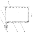
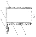
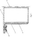
- Fig. 1 to Fig. 7 show hat profiles consisting of a U-profile 1, with a Cover plate 4 was closed.
- the internal rib structure 2 was there first inserted into the open U-profile by injection molding. Subsequently the cover plate 4 was attached using different methods.
- Fig. 1 shows a profile, the flange 10 between the U-profile 1 and cover plate 4 on the one hand by a plastic rivet connection 5 and on the other hand by a Snap connection held together using an additional snap element 6 becomes.
- the plastic rivet connection 5 in this embodiment reinforced by a positive connection 18 between U-profile 1 and cover plate 4 can be produced by injection molding as well as by ultrasonic welding become.
- the rib structure 2 itself is over molded connecting elements 7,8 positively attached to U-profile 1 and cover plate 4.
- the additional connection of U-profile 1 and cover plate 4 by means of central struts 9 within the Rib structure 2 increases the rigidity of the beam.
- Fig. 2 describes a simple carrier, in the U-profile 1 and cover plate 4 only are connected in the flange area 10 by a plastic rivet 5.
- connection of U-profile 1 and cover plate 4 takes place with the help of Plastic rivet connections 12, 13 both in the flange area 10 and via the central struts 9 of the rib structure 4.
- the rivet connection 13 in the flange area 10 can be produced by injection molding as well as by ultrasonic welding become.
- the rivet connection 12 in the area of the central struts 9 of the rib structure 4 can only be achieved by ultrasonic welding.
- connection of U-profile 1 and cover plate 4 is in the lightweight component according to Fig. 4 reached by crumbs.
- the holes 14 in the ductile cover plate 4 deformed so that a positive connection of the cover plate 4 with the U-profile results in 1.
- FIG. 6 shows a partial view of a lightweight component Connecting elements in the flange area 10 between U-profile 1 and cover plate 4, which is obtained primarily through clinched holes 16, which are subsequently through Overmold 19 can be additionally secured with plastic.
- a double hat profile is shown, which in several places on the longitudinal axis of the profiles 20 and 1 connecting points 21.
- Housing part 1 and cover shell 20 are here the same shaped profile plates, which are on different connection surfaces Have contact.
- the profile plates 1, 20 have the connection points 21 Superimposed openings 3.
- the connection points 21 are made of plastic rivets 5 held together at the openings 3, both by injection molding and can also be shaped by ultrasonic welding.
- the inside Rib structure 32 in this case is produced by extrusion. It is only in the cavities 23 of the U-profiles 1 and 20 inserted and by connecting them positively held in the carrier 20, 1.
- Fig. 9 shows the connection of two carriers in the form of a T-node. Doing so closed plastic-metal hybrid carrier 25 with a pure metal carrier 26 connected.
- the closed hybrid carrier 25 consists of a U-profile sheet 1 and a cover plate 4 and an internal rib structure 2.
- the connection of U-profile 1 and cover plate 4 takes place in several places.
- Connecting elements with the aid of plastic rivets 5 or 12 in the flange area 10 and created in the area of the struts 9 of the rib structure 2 (similar to that Execution in Fig. 1 and Fig. 3).
- the strength of the connection between the U-profile 1 and cover plate 4 further reinforced (comparable to the cross section according to FIG. 6).
- the two supports 25 and 26 are connected by two connecting plates 27, the plastic rivet 5 with the hybrid support 25 and the plastic rivet 28 are connected to the pure metal support 26.
- the using plastic rivets 30 and edge molding 31 attached between the connecting plates 27 further rib structures 29 prevent premature bulging of the Connection plates 27, whereby a reinforcement of the entire T node is achieved becomes. So that the rib structures 29 are always subjected to pressure, the connecting plates 27 in the area of the rib structures 29 are cambered inwards.
- U-profile (1) support structure; Rib structure (2) openings 3 cover plate; Cover plate (4) plastic rivet connection (5) snap element (6) molded connecting elements (7, 8) struts (9) edge area; Flange area (10) plastic rivet connections (12, 13) holes (14) connection points (15) clinched holes (16) joining part (17) form fit (18) cover shell; Profile (20) fasteners (21) recesses (23) overmolding (24) hybrid carrier (25) metal carrier (26) connecting plates (27), plastic rivets (28) rib structures (29) Plastic rivets (30) and edge molding (31)
Landscapes
- Engineering & Computer Science (AREA)
- Mechanical Engineering (AREA)
- Architecture (AREA)
- Structural Engineering (AREA)
- Chemical & Material Sciences (AREA)
- Combustion & Propulsion (AREA)
- Transportation (AREA)
- Manufacturing & Machinery (AREA)
- Connection Of Plates (AREA)
- Body Structure For Vehicles (AREA)
- Forklifts And Lifting Vehicles (AREA)
- Golf Clubs (AREA)
- Fluid-Damping Devices (AREA)
- Injection Moulding Of Plastics Or The Like (AREA)
- Lining Or Joining Of Plastics Or The Like (AREA)
- Glass Compositions (AREA)
- Casings For Electric Apparatus (AREA)
Abstract
Description
Bei diesem bevorzugten Herstellungsverfahren kann die Anbindung sowohl durch Spritzgießen als auch durch Kunststoffnieten mittels zuvor angeformter Verbindungselemente erreicht werden. In beiden Fällen wird das Gehäuseteil mit Durchbrüchen versehen (z.B. Metallblech mit Bohrungen), durch die ein formschlüssiger Verbund mit der Rippenstruktur erreicht wird.
Bei der Anbindung durch Spritzgießen wird zunächst ein offenes Gehäuseteil in ein Spritzgießwerkzeug eingelegt. Durch den Spritzgießprozeß wird sowohl die Rippenstruktur geformt als auch die Anbindung an das Gehäuseteil erreicht. Da das Kunststoffmaterial in flüssiger Form in das Spritzgießwerkzeug gefüllt wird, kann es die Durchbrüche in dem Gehäuseteil durchströmen und auf der Rückseite der Durchbrüche einen Nietkopf bilden. Anschließend wird das Hohlkammer-Bauteil durch Anbringen (z.B. Verschweißen) mindestens eines weiteren äußeren Teils - hier als Deckplatte oder Deckschale bezeichnet - komplettiert.
In ähnlicher Weise kann auch bei Anwendung des Kunststoffnietens (Zapfenschweißen) eine Anbindung der Rippenstruktur an das Gehäuseteil erzielt werden. Dabei wird zunächst die Rippenstruktur separat ohne Gehäuseteil, aber mit angeformten Verbindungszapfen, gespritzt. Anschließend werden die äußeren Teile (Gehäuseteil und Deckplatte) um die Rippenstruktur gelegt wobei die Verbindungszapfen durch die Durchbrüche der äußeren Teile ragen. Anschließend werden die Verbindungszapfen mit Hilfe eines Umformprozesses (z.B. durch Ultraschallschweißen) zu einem Nietkopf umgeformt. Bei dieser Vorgehensweise kann das Leichtbauteil durch diesen abschließenden Schweißvorgang komplettiert werden, indem die erforderlichen Außenteile in entsprechender Weise um die Rippenstruktur angeordnet werden.
Bei diesem weiteren bevorzugten Verfahren wird ebenfalls zunächst eine separate Rippenstruktur hergestellt. Auch hier gibt es wieder mehrere Möglichkeiten. Einerseits kann die Rippenstruktur aus einem extrudierten Profil geformt sein, das einfach zwischen die Außenteile des Leichtbauteils (das Gehäuseteil und Deckplatte oder Deckschale) gelegt wird. Durch Verbinden der Außenteile erhält man dann den Formschluß. Auf der anderen Seite kann auch eine spritzgegossene Rippenstruktur mit angeformten Zapfen verwendet werden, die ebenfalls zwischen den Außenteilen des Leichtbauteils angeordnet wird, um dann durch Verbinden der Außenteile des Leichtbauteils einen Formschluß zwischen Rippenstruktur und Außenteil zu erzielen. Dabei werden die angeformten Zapfen der Rippenstruktur in Durchbrüche der Außenteile gesteckt, um eine verbesserte Anbindung der Rippenstruktur an die Außenhaut zu erreichen.
Ähnlich wie die Anbindung der Rippenstruktur an die Außenteile des Leichtbauteils können auch die Außenteile (Gehäuseteil und Deckplatte/Deckschale) untereinander verbunden werden. Dabei können ebenfalls zuvor angeformte Verbindungszapfen der Rippenstruktur genutzt werden, um mit Hilfe eines Umformprozesses einen Formschluß zwischen Rippenstruktur und den verschiedenen Außenteilen und/oder direkt zwischen den Außenteilen zu realisieren. Soll die Verbindung mittels Spritzgießen erreicht werden, müssen die Außenteile unmittelbar übereinander liegen bzw. dürfen nur einen geringen Abstand voneinander haben. Dies läßt sich insbesondere im Randbereich von Profilen oder partiell an Sicken realisieren. Wird die Verbindung durch Umformen der Verbindungszapfen mittels Ultraschall durchgeführt, sind auch direkte Verbindungen von Rippen mit Außenteilen möglich.
Ein direktes stoffschlüssiges oder formschlüssiges Verbinden der Außenteile (Gehäuseteil und Deckplatte/Deckschale) des Leichtbauteiles kann bei Verwendung von Metallblechen durch Punktschweißen, Clinchen (d.h. Verbinden zweier oder mehrerer übereinanderliegender Bleche durch partielles Verformen bestimmter Stellen der Bleche zu einer pilzförmigen Vertiefung, die eine formschlüssige Verbindung der Bleche ergibt) oder durch Kleben erreicht werden. Sofern die Außenteile aus Kunststoff-Composites hergestellt werden, kann partielles Schweißen oder ebenfalls Kleben zur Anwendung kommen.
- Figur 1
- den Querschnitt durch ein erfindungsgemäßes Leichtbauteil
- Figur 1a
- die Teilansicht einer Aufsicht auf das Leichtbauteil nach Fig. 1
- Figur 2
- die Teilansicht eines Leichtbauteiles ähnlich Fig. 1 mit Kunststoffnietverbindung
- Figur 3
- die Teilansicht eines Leichtbauteiles ähnlich Fig. 1 mit Kunststoffnietverbindung und mit dem Deckteil 4 verbundener Stützstruktur 9
- Figur 4
- die Teilansicht eines Leichtbauteiles ähnlich Fig. 1 mit einer Börtelverbindung von Profil 1 und Deckteil 4
- Figur 5
- die Teilansicht eines Leichtbauteiles ähnlich Fig. 1 mit einer Clinchverbindung von Profil 1 und Deckteil 4
- Figur 6
- die Teilansicht eines Leichtbauteiles ähnlich Fig. 1 mit einer Clinchverbindung von Profil 1 und Deckteil 4 und zusätzlicher Kunststoffumspritzung 19
- Figur 7
- die Teilansicht eines Leichtbauteiles ähnlich Fig. 1 mit einer Clinchverbindung von Profil 1, Fügeteil 17 und Deckteil 4
- Figur 8
- Aufsicht und Schnitt durch ein Leichtbauteil in Form eines Doppelhutprofiles
- Figur 9
- T-Knotenverbindung zweier erfindungsgemäßer Leichtbauteile mit einem konventionellen Metallträger
Claims (25)
- Hoch mechanisch beanspruchbares Hohlkammer-Leichtbauteil bestehend mindestens aus wenigstens einem schalenförmigen Gehäuseteil (1) aus hochfestem Werkstoff, insbesondere aus einem von Kunststoff verschiedenen Werkstoff, insbesondere bevorzugt aus Metall, und einer gerippten Stützstruktur (2) aus Kunststoff, insbesondere aus thermoplastischem Kunststoff, wobei die Stützstruktur (2) auf der Innenseite des Gehäuseteiles (1) anliegt und insbesondere mit dem Gehäuseteil (1) verbunden ist, und wenigstens einer Deckplatte (4) oder Deckschale (20) aus einem, insbesondere von Kunststoff verschiedenen, hochfesten Werkstoff, insbesondere aus Metall, die den aus Gehäuseteil (1) und Stützstruktur (2) gebildeten Raum weitgehend abdeckt und in ihrem Randbereich wenigstens mit einem Teil der Umrandung (10) des Gehäuseteiles (1) verbunden ist.
- Leichtbauteil nach Anspruch 1, dadurch gekennzeichnet, daß die Stützstruktur (2) mit dem Gehäuseteil (1) formschlüssig, insbesondere mittels Spritzguß verbunden ist.
- Leichtbauteil nach Anspruch 1 oder 2, dadurch gekennzeichnet, daß die Stützstruktur (2) mit dem Gehäuseteil (1) durch Zapfen, die an die Stützstruktur (2) angeformt sind und zu Kunststoffnieten umgeformt sind, formschlüssig verbunden ist.
- Leichtbauteil nach einem der Ansprüche 1 bis 3, dadurch gekennzeichnet, daß die Deckplatte (4) oder die Deckschale (20) ebenfalls mit einer Stützstruktur (32) aus Kunststoff versehen ist.
- Leichtbauteil nach einem der Ansprüche 1 bis 4, dadurch gekennzeichnet, daß die Deckplatte (4) oder Deckschale (20) auf ihrer Außenseite (11), insbesondere im Bereich ihrer Verbindung zum Gehäuseteil (1), eine teilweise oder vollständige Ummantelung oder Überspritzung (19, 24) mit thermoplastischem Kunststoff aufweist.
- Leichtbauteil nach einem der Ansprüche 1 bis 5, dadurch gekennzeichnet, daß die Deckplatte (4) oder Deckschale (20) mit dem Gehäuseteil (1) an unmittelbar aufeinander liegenden Stellen, insbesondere im Bereich von übereinander liegenden Durchbrüchen (3) mittels thermoplastischem Kunststoff formschlüssig miteinander verbunden ist.
- Leichtbauteil nach einem der Ansprüche 1 bis 6, dadurch gekennzeichnet, daß die Deckschale (20) bzw. die Deckplatte (4) mit der Stützstruktur (2) und/oder dem Gehäuseteil (1) verschweißt bzw. mittels Kunststoffnieten verbunden ist, wobei auf Rippen (9) der Stützstruktur (2) vorgesehene Kunststoffzapfen (8) formschlüssig in Hinterschnitte des Gehäuseteiles (1) bzw. der Deckschale (20) oder der Deckplatte (4) eingreifen.
- Leichtbauteil nach einem der Ansprüche 1 bis 7, dadurch gekennzeichnet, daß die Deckschale (20) bzw. die Deckplatte (4) mit der Stützstruktur (2) und/oder dem Gehäuseteil (1) durch Schweißen übereinander liegender Flächen (insbesondere durch Reibschweißen zur Erzeugung einer Kunststoff-Kunststoff- oder Kunststoff-Werkstoff Verbindung), durch Verschweißen übereinander liegender Kanten, durch Punktschweißen, Kleben, Börteln, Clinchen, Nieten, Kunststoff-Nieten, Zapfenschweißen von Kunststoffzapfen oder einer beliebigen Kombination dieser Verfahren verbunden ist.
- Leichtbauteil nach einem der Ansprüche 1 bis 8, dadurch gekennzeichnet, daß die Stützstruktur (2) mit der Wand des Gehäuseteiles (1) mittels spritzgegossenen formschlüssigen Verbindungen (7, 8, 5) im Bereich von Durchbrüchen und/oder Sicken in der Wand verbunden ist.
- Leichtbauteil nach einem der Ansprüche 1 bis 9, dadurch gekennzeichnet, daß die Stützstruktur (2) mit dem Gehäuseteil (1) mittels Steckverbindungen oder Schnappverbindungen (6) formschlüssig verbunden ist.
- Leichtbauteil nach einem der Ansprüche 1 bis 10, dadurch gekennzeichnet, daß die Stützstruktur (2) mit dem Gehäuseteil (1) durch Kleb- und/oder Schweißverbindungen stoffschlüssig verbunden ist.
- Leichtbauteil nach einem der Ansprüche 1 bis 11, dadurch gekennzeichnet, daß das Gehäuseteil (1) und/oder die Deckplatte (4) oder Deckschale (20) aus Metallblech, bevorzugt aus Stahl- oder Aluminium-Blech, oder aus Druckgußteilen, bevorzugt aus Aluminium, Zink oder Magnesium oder aus faserverstärktem Kunststoff bzw. Composites besteht.
- Leichtbauteil nach einem der Ansprüche 1 bis 12, dadurch gekennzeichnet, daß der Kunststoff der Stützstruktur (2) ein, insbesondere verstärkter und/oder gefüllter Thermoplast, bevorzugt ein Polycarbonat (PC), Polyester, Polyurethan, Polystyrol, ABS, Polyamid (PA), Polybutylenterephthalat (PBT), oder Polypropylen (PP) ist.
- Leichtbauteil nach einem der Ansprüche 1 bis 13, dadurch gekennzeichnet, daß das Leichtbauteil teilweise Öffnungen zu dem aus Gehäuseteil (1) und Deckplatte (4) oder Deckschale (20) gebildeten Raum aufweist.
- Leichtbauteil nach einem der Ansprüche 1 oder 5 bis 8, dadurch gekennzeichnet, daß die Stützstruktur (2, 32) lediglich in das Gehäuseteil (1) eingelegt ist.
- Verwendung eines Leichtbauteils nach einem der Ansprüche 1 bis 15 als Längsträger, Querträger, Bodengruppenbauteil, Querlenker, energieabsorbierende Seiten- oder Stirnwand oder als Stoßfängerträger im Fahrzeugbau oder Flugzeugbau.
- Verwendung eines Leichtbauteils nach einem der Ansprüche 1 bis 15 als Knotenelement zur Verbindung von Trägern, insbesondere im Fahrzeugbau.
- Verfahren zur Herstellung von hoch mechanisch beanspruchbaren Leichtbauteilen als Kunststoff-Werkstoff-Verbund in Hybridbauweise bestehend mindestens aus wenigstens einem schalenförmigen Gehäuseteil (1), wenigstens einer Deckplatte (4) oder Deckschale (20) und einer von diesen Teilen eingeschlossenen gerippten Stützstruktur (2), dadurch gekennzeichnet, daß wenigstens ein Gehäuseteil (1) aus einem hochfesten Werkstoff oder Werkstoffverbund auf seiner Innenseite mit einer Stützstruktur (2) aus Kunststoff versehen wird und anschließend mit einer Deckplatte (4) oder Deckschale (20) aus einem hochfesten Werkstoff oder Werkstoffverbund verbunden wird.
- Verfahren nach Anspruch 18, dadurch gekennzeichnet, daß in einem ersten Schritt die Stützstruktur (2) auf das Gehäuseteil (1) durch Spritzgießen aufgebracht wird, indem die Rippen (9, 13, 29) der Stützstruktur (2) über Formschlüsse (7, 8), die Bestandteil der Stützstruktur (2) sind, mit der Wand des Gehäuseteiles (1) verbunden werden und in einem zweiten Schritt mit einem Deckblech (4) oder Deckschale (20) verschlossen wird.
- Verfahren nach einem der Ansprüche 18 bis 19, dadurch gekennzeichnet, daß die Deckplatte (4) oder die Deckschale (20) vor dem Verschließen des Gehäuseteiles (1) mit einer eigenen Stützstruktur aus Kunststoff versehen und/oder teilweise oder vollständig mit Kunststoff überspritzt bzw. ummantelt wird.
- Verfahren nach einem der Ansprüche 18 bis 20, dadurch gekennzeichnet, daß die Deckplatte (4) oder Deckschale (20) mit dem Gehäuseteil (1) an unmittelbar aufeinander liegenden Stellen, insbesondere im Bereich von Durchbrüchen (3) mittels thermoplastischem Kunststoff formschlüssig miteinander verbunden werden.
- Verfahren nach einem der Ansprüche 18 bis 21, dadurch gekennzeichnet, daß die Deckschale (20) bzw. die Deckplatte (4) mit der Stützstruktur (2) und/oder dem Gehäuseteil (1) verschweißt bzw. mittels Kunststoffnieten verbunden werden, wobei auf Rippen (9, 13, 29) der Stützstruktur (2) vorgesehene Kunststoffzapfen (7, 8) formschlüssig in Hinterschnitte des Gehäuseteiles (1) bzw. der Deckschale (20) oder der Deckplatte (4) eingreifen.
- Verfahren nach einem der Ansprüche 18 bis 22, dadurch gekennzeichnet, daß die Deckschale (20) bzw. die Deckplatte (4) mit der Stützstruktur (2) und/oder dem Gehäuseteil (1) durch Schweißen übereinander liegender Flächen (insbesondere durch Reibschweißen zur Erzeugung einer Kunststoff-Kunststoff- oder Kunststoff-Werkstoff Verbindung), durch Verschweißen übereinander liegender Kanten, durch Punktschweißen, Kleben, Börteln, Clinchen, Nieten, Kunststoff-Nieten, Zapfenschweißen von Kunststoffzapfen oder einer beliebigen Kombination dieser Verfahren verbunden wird.
- Verfahren nach einem der Ansprüche 18 bis 23, dadurch gekennzeichnet, daß die Stützstruktur (2) vor dem Verschliessen des Gehäuseteiles (1) durch Stecken oder Schnappen mit dem Gehäuseteil (1) formschlüssig verankert wird.
- Verfahren nach einem der Ansprüche 18 bis 24, dadurch gekennzeichnet, daß die Stützstruktur (2) vor dem Verschliessen des Gehäuseteiles (1) durch Kleben und/oder Schweißen stoffschlüssig mit dem Gehäuseteil (1) verbunden wird.
Applications Claiming Priority (2)
| Application Number | Priority Date | Filing Date | Title |
|---|---|---|---|
| DE19848516 | 1998-10-21 | ||
| DE19848516A DE19848516A1 (de) | 1998-10-21 | 1998-10-21 | Hohlkammer-Leichtbauteil |
Publications (2)
| Publication Number | Publication Date |
|---|---|
| EP0995668A1 true EP0995668A1 (de) | 2000-04-26 |
| EP0995668B1 EP0995668B1 (de) | 2004-01-07 |
Family
ID=7885178
Family Applications (1)
| Application Number | Title | Priority Date | Filing Date |
|---|---|---|---|
| EP99119917A Revoked EP0995668B1 (de) | 1998-10-21 | 1999-10-08 | Hohlkammer-Leichtbauteil |
Country Status (7)
| Country | Link |
|---|---|
| US (1) | US6503585B1 (de) |
| EP (1) | EP0995668B1 (de) |
| JP (1) | JP2000130689A (de) |
| AT (1) | ATE257446T1 (de) |
| DE (2) | DE19848516A1 (de) |
| ES (1) | ES2214788T3 (de) |
| PL (1) | PL336136A1 (de) |
Cited By (42)
| Publication number | Priority date | Publication date | Assignee | Title |
|---|---|---|---|---|
| FR2799717A1 (fr) * | 1999-09-28 | 2001-04-20 | Bosch Gmbh Robert | Element de support pour vehicule automobile |
| WO2001054964A1 (de) * | 2000-01-27 | 2001-08-02 | Behr Gmbh & Co. | Bauteil für ein kraftfahrzeug |
| US6398259B1 (en) | 2001-04-18 | 2002-06-04 | Bayer Corporation | Break-away bracket |
| FR2818605A1 (fr) * | 2000-12-22 | 2002-06-28 | Faurecia Ind | Bloc avant comprenant une face avant et des blocs optiques perfectionnes, et vehicule automobile correspondant |
| GB2370803A (en) * | 2000-11-07 | 2002-07-10 | Maier S Coop Ltda | Composite structural element for vehicles and the like |
| EP1227031A1 (de) * | 2000-01-17 | 2002-07-31 | Faurecia Industries | Strukturelement mit Gehäuseteil und gerippter Stützstruktur, und korrespondierendes Kraftfahrzeug |
| EP1227030A1 (de) * | 2001-01-30 | 2002-07-31 | Ford Global Technologies, Inc., A subsidiary of Ford Motor Company | Verwendung eines Profilträgers einer lastaufnehmenden Struktur in verschiedenen Konstruktionsvarianten |
| EP1232935A1 (de) * | 2001-02-19 | 2002-08-21 | Adam Opel Ag | Fahrzeugkarosserie |
| WO2002064343A1 (de) * | 2001-02-13 | 2002-08-22 | Bayer Aktiengesellschaft | Verfahren zur herstellung von verbundteilen durch mehrkomponentenspritzguss |
| EP1234752A1 (de) * | 2001-02-26 | 2002-08-28 | Compagnie Plastic Omnium | Kraftfahrzeug-Glasscheibe mit umgebender Profilleiste, und Fahrzeugflügel mit derartiger Glasscheibe |
| WO2002068257A1 (en) * | 2001-02-28 | 2002-09-06 | E.I. Dupont De Nemours And Company | Integral structures of metal and plastic with fastening means |
| WO2002068258A1 (en) * | 2001-02-28 | 2002-09-06 | E.I. Dupont De Nemours And Company | Integral structures of metal and plastic |
| EP1251057A3 (de) * | 2001-04-18 | 2003-01-15 | Bayer Corporation | Lagerungskasten für eine Lenkwelle |
| EP1084816A3 (de) * | 1999-09-16 | 2003-01-22 | Basf Aktiengesellschaft | Verbundbauteil |
| WO2003037700A1 (de) * | 2001-10-31 | 2003-05-08 | Imperia Gesellschaft für angewandte Fahrzeugentwicklung mbH | Leichtbauteil, insbesondere karosserieteil |
| WO2003042023A1 (de) * | 2001-11-13 | 2003-05-22 | ZF Lemförder Metallwaren AG | Kraftverbindungsstrebe |
| US6595502B2 (en) | 2000-10-30 | 2003-07-22 | Bayer Aktiengesellschaft | Bumper system for vehicles |
| WO2004022416A1 (de) * | 2002-08-16 | 2004-03-18 | Hella-Behr Fahrzeugsysteme Gmbh | Hybridbauteil mit spritzguss-kunstoffverbindern für kraftfahrzeuge und verfahren zur seiner reparatur |
| US6811195B2 (en) | 2001-10-08 | 2004-11-02 | Bayer Aktiengesellschaft | Composite structural article for frame structures |
| WO2005035339A1 (de) * | 2003-10-08 | 2005-04-21 | Behr Gmbh & Co. Kg | Bauteil und verwendung eines derartigen bauteils sowie verfharen zur herstellung eines bauteils |
| EP1593860A3 (de) * | 2004-05-04 | 2006-02-15 | Lanxess Deutschland GmbH | Verbundbauteil |
| FR2885585A1 (fr) * | 2005-05-16 | 2006-11-17 | Faurecia Bloc Avant | Ensemble d'ossature pour vehicule automobile, et vehicule automobile correspondant. |
| WO2007006476A1 (de) * | 2005-07-12 | 2007-01-18 | Hbpo Gmbh | Strukturträger als karosseriebauteil |
| WO2007059954A1 (de) * | 2005-11-23 | 2007-05-31 | Hbpo Gmbh | Montageträger in hybridstruktur |
| WO2007128395A2 (de) | 2006-05-04 | 2007-11-15 | Lanxess Deutschland Gmbh | Leichtbauteil in hybridbauweise |
| WO2007131492A1 (de) | 2006-05-15 | 2007-11-22 | Webasto Ag | Fahrzeugbauteil mit einer versteifung |
| EP1867559A2 (de) | 2006-06-14 | 2007-12-19 | Volkswagen Aktiengesellschaft | Aufprallschutzverstärkungsteil |
| DE102007006493A1 (de) | 2007-02-09 | 2008-08-14 | Lanxess Deutschland Gmbh | Leichtbauteil in Hybridbauweise |
| EP1495947A3 (de) * | 2003-07-11 | 2008-08-20 | Hella-Behr Fahrzeugsysteme GmbH | Hybridbauteil für Kraftfahrzeuge |
| DE102007025930A1 (de) | 2007-06-02 | 2008-12-04 | Lanxess Deutschland Gmbh | Verstärkungselement für einen Fahrzeug Hohlkörper |
| DE102007026762A1 (de) | 2007-06-09 | 2009-02-05 | Lanxess Deutschland Gmbh | Verstärkungselement für einen Fahrzeug Hohlkörper |
| DE102009008659A1 (de) * | 2009-02-12 | 2010-08-19 | Daimler Ag | Verbundbauteil und Verfahren zum Herstellen eines Verbundbauteils |
| DE202007019273U1 (de) | 2007-06-02 | 2012-01-02 | Lanxess Deutschland Gmbh | Verstärkungselement für einen Fahrzeug Hohlkörper |
| DE102011104368A1 (de) | 2011-06-16 | 2012-03-15 | Daimler Ag | Verbundhohlprofil und Verfahren zu dessen Herstellung |
| WO2012040480A3 (en) * | 2010-09-22 | 2012-05-10 | Basf Se | Polymer reinforced metallic roof bow |
| WO2012107272A1 (de) * | 2011-02-11 | 2012-08-16 | Zf Friedrichshafen Ag | Faserverbund-hybridlenker |
| WO2013041490A1 (fr) * | 2011-09-23 | 2013-03-28 | Peugeot Citroen Automobiles Sa | Panneau de protection destine a etre fixe sur une partie de la carrosserie d'un vehicule automobile et procede de fabrication d'un tel panneau |
| US8530015B2 (en) | 2006-01-17 | 2013-09-10 | Zephyros, Inc. | Reinforcement of hollow profiles |
| FR2999142A1 (fr) * | 2012-12-10 | 2014-06-13 | Hutchinson | Profile a portion(s) en u, element de structure porteuse d'un vehicule l'incorporant et procede de fabrication du profile. |
| EP2323891B1 (de) | 2008-08-12 | 2016-06-29 | Sika Technology AG | Strukturiertes verstärkungssystem |
| US9782950B2 (en) | 2008-11-07 | 2017-10-10 | Zephyros, Inc. | Hybrid reinforcement structure |
| DE102024003642A1 (de) | 2024-11-07 | 2026-05-07 | Mercedes-Benz Group AG | Karosseriebauteil und Herstellungsverfahren |
Families Citing this family (61)
| Publication number | Priority date | Publication date | Assignee | Title |
|---|---|---|---|---|
| US6854791B1 (en) * | 1999-10-20 | 2005-02-15 | Rcc Regional Compact Car Ag | Fiber-reinforced thermoplastic vehicle cell |
| IT1320526B1 (it) * | 2000-07-07 | 2003-12-10 | Fiat Ricerche | Giunto di interconnessione di elementi strutturali. |
| JP4621928B2 (ja) * | 2000-10-25 | 2011-02-02 | 株式会社 林物産発明研究所 | 構造部材および構造物 |
| DE10100914A1 (de) * | 2001-01-11 | 2002-07-18 | Bayer Ag | Plattenförmiges Leichtbauteil |
| DE10131465A1 (de) * | 2001-06-29 | 2003-01-09 | Bayer Ag | Solarenergiekollektor |
| US6644722B2 (en) * | 2002-01-17 | 2003-11-11 | Bayer Corporation | Molded article having a rigid support and a rigid hollow member |
| US6672642B1 (en) * | 2002-06-11 | 2004-01-06 | Alcoa Inc. | Hybrid tailgate |
| DE20310156U1 (de) * | 2002-07-05 | 2003-09-25 | Decoma (Germany) GmbH, 66280 Sulzbach | Metallprofilteil |
| US20040091666A1 (en) * | 2002-11-12 | 2004-05-13 | Roberts Ronald K. | Structural composite member |
| DE10317218A1 (de) * | 2003-04-15 | 2004-11-04 | Bayer Ag | Verfahren zur Herstellung eines Kunststoff-Metall-Verbundbauteils |
| DE10317217A1 (de) * | 2003-04-15 | 2004-11-04 | Bayer Ag | Hohlkammer-Verbundbauteil |
| JP4403789B2 (ja) * | 2003-05-27 | 2010-01-27 | トヨタ自動車株式会社 | 多段変速機 |
| DE10329710A1 (de) * | 2003-07-02 | 2005-02-10 | Bayer Aktiengesellschaft | Verfahren zur Herstellung eines Kunststoff-Metall-Verbundbauteils |
| DE102004050162A1 (de) * | 2003-10-14 | 2005-07-14 | Behr Gmbh & Co. Kg | Verbundbauteil, insbesondere Querträger |
| JP4662575B2 (ja) * | 2004-05-31 | 2011-03-30 | 株式会社タカギセイコー | 中空部にインサート部材を固定した樹脂成形品及びその成形方法 |
| FR2871427B1 (fr) * | 2004-06-14 | 2006-09-29 | Faurecia Bloc Avant | Element structurel hybride pour vehicule automobile et vehicule equipe d'un tel element |
| DE102004049512B4 (de) * | 2004-10-11 | 2013-11-28 | Bürkert Werke GmbH | Modulares Gehäusesystem für fluidische Steuer- und Regelgeräte |
| DE102005004917B4 (de) * | 2005-02-02 | 2013-02-28 | Benteler Automobiltechnik Gmbh | Lenkerbauteil für Radaufhängungen von Kraftfahrzeugen und Verfahren zu seiner Herstellung |
| DE102005018976A1 (de) * | 2005-04-23 | 2006-10-26 | Bayerische Motoren Werke Ag | Kraftfahrzeugkarosserie |
| DE102005034621B3 (de) | 2005-07-19 | 2007-01-11 | Deutsches Zentrum für Luft- und Raumfahrt e.V. | Verbundstruktur und Verfahren zur Herstellung einer Verbundstruktur |
| DE102005036249B4 (de) * | 2005-08-02 | 2007-08-23 | Seeber Ag & Co. Kg | Baugruppe, umfassend ein Kunststoffteil und ein mit diesem verbundenes Blechteil |
| DE102005050963B4 (de) * | 2005-10-25 | 2008-07-03 | Audi Ag | Bauteil und Verfahren zum Herstellen eines Bauteils |
| DE102005057181A1 (de) * | 2005-11-29 | 2007-06-06 | Lanxess Deutschland Gmbh | Verbinden von faserverstärktem Material mit einem Spritzgussmaterial |
| DE102007011107B4 (de) | 2007-03-05 | 2011-05-05 | Stiftung Alfred-Wegener-Institut Für Polar- Und Meeresforschung | Technische Leichtbaukonstruktion mit einer fraktal gegliederten Stützstruktur |
| DE102007041222A1 (de) * | 2007-08-31 | 2009-03-05 | Lear Corp., Southfield | Fahrzeugsitz-Verbundrahmen |
| US8042847B2 (en) * | 2007-12-19 | 2011-10-25 | Sabic Innovative Plastics Ip B.V. | Tray energy absorber and bumper system |
| KR100983828B1 (ko) * | 2008-02-01 | 2010-09-27 | 이희만 | 철재 팔레트 |
| JP5167204B2 (ja) * | 2008-07-04 | 2013-03-21 | 大成プラス株式会社 | 接合薄板金属構造体 |
| DE102010015972B4 (de) * | 2010-03-15 | 2022-03-24 | Deutsches Zentrum für Luft- und Raumfahrt e.V. | Energieabsorptionsvorrichtung zur Absorption von Aufprallenergie und Fahrzeug mit mindestens einer Energieabsorptionsvorrichtung |
| DE102010012715A1 (de) | 2010-03-25 | 2011-09-29 | Daimler Ag | Strukturbauteil für eine Fahrzeugkarosserie |
| WO2011135453A1 (en) * | 2010-04-08 | 2011-11-03 | Magna International Inc. | Shipping pallet post reinforcement |
| DE102010014503A1 (de) | 2010-04-10 | 2011-10-13 | Daimler Ag | Strukturbauteil für einen Kraftwagen und Verfahren zu dessen Herstellung |
| DE102010030484A1 (de) * | 2010-06-24 | 2011-12-29 | Zf Friedrichshafen Ag | Modulares Leichtbau-Strebenelement |
| JP2012011619A (ja) * | 2010-06-30 | 2012-01-19 | Kojima Press Industry Co Ltd | クリップ結合構造 |
| US8336933B2 (en) | 2010-11-04 | 2012-12-25 | Sabic Innovative Plastics Ip B.V. | Energy absorbing device and methods of making and using the same |
| US8322780B2 (en) | 2010-12-20 | 2012-12-04 | Sabic Innovative Plastics Ip B.V. | Reinforced body in white and method of making and using the same |
| CN102180196B (zh) * | 2011-03-15 | 2012-09-26 | 东风汽车公司 | 基于车身壳体轻量化解决车身壳体薄弱部位防冲击的方法及其结构 |
| JP5797496B2 (ja) * | 2011-08-24 | 2015-10-21 | 本田技研工業株式会社 | 樹脂板材の結合構造および樹脂板材の結合方法 |
| DE102012015245A1 (de) * | 2012-06-01 | 2013-12-05 | Westfalia-Automotive Gmbh | Trägeranordnung für eine Anhängekupplung mit einem Mehrkomponenten-Tragbauteil |
| US8864216B2 (en) | 2013-01-18 | 2014-10-21 | Sabic Global Technologies B.V. | Reinforced body in white and method of making and using the same |
| US9067550B2 (en) | 2013-01-18 | 2015-06-30 | Sabic Global Technologies B.V. | Polymer, energy absorber rail extension, methods of making and vehicles using the same |
| FR3009098B1 (fr) * | 2013-07-26 | 2017-06-09 | Coutier Moulage Gen Ind | Procede de fabrication d’une pedale creuse bi-matiere et pedale correspondante |
| DE102013022104A1 (de) * | 2013-12-23 | 2015-06-25 | Mac Panther Gmbh | Verbindungsstütze mit Korrosionsschutz |
| DE102014000055B4 (de) * | 2014-01-08 | 2015-08-06 | Imperia Gesellschaft für angewandte Fahrzeugentwicklung mbH | Leichtbauteil und Verfahren zu dessen Herstellung |
| EP3513958B1 (de) | 2014-06-16 | 2024-09-25 | SABIC Global Technologies B.V. | Verfahren zur herstellung eines laminats |
| DE102014216001A1 (de) * | 2014-08-13 | 2016-02-18 | Bayerische Motoren Werke Aktiengesellschaft | Bauteilverbindung und Verfahren zum plastischen Umformen einer Kugel |
| JP6109271B2 (ja) * | 2015-02-06 | 2017-04-05 | 株式会社神戸製鋼所 | 接合構造体、及び接合構造体の製造方法 |
| EP3334640B1 (de) | 2015-08-11 | 2020-11-18 | Carbon Truck & Trailer GmbH | Selbsttragendes untergestell für ein fahrzeug sowie ein solches fahrzeug |
| DE102015010886A1 (de) * | 2015-08-20 | 2017-02-23 | Hbpo Gmbh | Strukturbauteil für ein Kraftfahrzeug und Verfahren zur Herstellung |
| USD820749S1 (en) | 2015-12-29 | 2018-06-19 | Sabic Global Technologies B.V. | Roof component for a motor vehicle |
| US20170361540A1 (en) | 2016-06-16 | 2017-12-21 | GM Global Technology Operations LLC | Ultrasonic welding of dissimilar sheet materials |
| DE102016214996A1 (de) | 2016-08-11 | 2018-02-15 | Bayerische Motoren Werke Aktiengesellschaft | Kraftfahrzeug |
| DE102016117903A1 (de) * | 2016-09-22 | 2018-03-22 | Dr. Ing. H.C. F. Porsche Aktiengesellschaft | Karosserieteilanordnung für ein Kraftfahrzeug und Verfahren zur Herstellung einer derartigen Karosserieteilanordnung |
| WO2018189635A1 (en) * | 2017-04-10 | 2018-10-18 | Sabic Global Technologies B.V. | Hybrid structure and method for manufacturing |
| DE102018202475A1 (de) * | 2018-02-19 | 2019-08-22 | Brose Fahrzeugteile Gmbh & Co. Kommanditgesellschaft, Bamberg | Strukturbauteil mit mehreren Organoblechstücken und Verfahren zu dessen Herstellung |
| CN114364555A (zh) * | 2019-06-21 | 2022-04-15 | 麦格纳外饰公司 | 三维包覆成型件 |
| DE102019132574B4 (de) * | 2019-12-02 | 2024-12-12 | Audi Ag | Kraftfahrzeug |
| JP6957054B1 (ja) * | 2020-05-14 | 2021-11-02 | 株式会社アルテクス | リベット接合方法及び接合処理装置 |
| DE102020125247A1 (de) | 2020-09-28 | 2022-03-31 | Audi Aktiengesellschaft | Verfahren zum Fügen zumindest zweier Fügepartner sowie Bauteilverbund |
| CN116446562B (zh) * | 2023-03-23 | 2026-04-03 | 中国五冶集团有限公司 | 一种在装配箱结构板上安装改性石膏隔墙板的施工方法 |
| KR102863964B1 (ko) | 2023-11-02 | 2025-09-23 | 김병찬 | 전기차 배터리케이스 프레임을 위한 냉각판 사출접합방법 |
Citations (2)
| Publication number | Priority date | Publication date | Assignee | Title |
|---|---|---|---|---|
| US3462330A (en) * | 1965-12-09 | 1969-08-19 | Woodall Industries Inc | Method for making a hollow plastic core structure |
| EP0370342A2 (de) | 1988-11-25 | 1990-05-30 | Bayer Ag | Leichtbauteil |
Family Cites Families (6)
| Publication number | Priority date | Publication date | Assignee | Title |
|---|---|---|---|---|
| US3695187A (en) * | 1970-10-09 | 1972-10-03 | Leroy Weiss | Adjustable pallet |
| US4843976A (en) * | 1988-08-09 | 1989-07-04 | Pigott Maurice J | Plastic pallet |
| US5190803A (en) | 1988-11-25 | 1993-03-02 | Bayer Aktiengesellschaft | Structural shell with reinforcing ribs connected via perforations |
| US5046434A (en) * | 1990-05-02 | 1991-09-10 | Penda Corporation | Plastic reinforced thermoformed pallet |
| US5667908A (en) * | 1996-01-26 | 1997-09-16 | Gnb Technologies, Inc. | Pedestal and cell tray assembly for lead-acid cells and batteries |
| US6096403A (en) * | 1997-07-21 | 2000-08-01 | Henkel Corporation | Reinforced structural members |
-
1998
- 1998-10-21 DE DE19848516A patent/DE19848516A1/de not_active Withdrawn
-
1999
- 1999-10-08 DE DE59908237T patent/DE59908237D1/de not_active Revoked
- 1999-10-08 EP EP99119917A patent/EP0995668B1/de not_active Revoked
- 1999-10-08 AT AT99119917T patent/ATE257446T1/de not_active IP Right Cessation
- 1999-10-08 ES ES99119917T patent/ES2214788T3/es not_active Expired - Lifetime
- 1999-10-18 US US09/419,520 patent/US6503585B1/en not_active Expired - Fee Related
- 1999-10-19 JP JP11296527A patent/JP2000130689A/ja active Pending
- 1999-10-21 PL PL99336136A patent/PL336136A1/xx not_active Application Discontinuation
Patent Citations (2)
| Publication number | Priority date | Publication date | Assignee | Title |
|---|---|---|---|---|
| US3462330A (en) * | 1965-12-09 | 1969-08-19 | Woodall Industries Inc | Method for making a hollow plastic core structure |
| EP0370342A2 (de) | 1988-11-25 | 1990-05-30 | Bayer Ag | Leichtbauteil |
Cited By (61)
| Publication number | Priority date | Publication date | Assignee | Title |
|---|---|---|---|---|
| EP1084816A3 (de) * | 1999-09-16 | 2003-01-22 | Basf Aktiengesellschaft | Verbundbauteil |
| FR2799717A1 (fr) * | 1999-09-28 | 2001-04-20 | Bosch Gmbh Robert | Element de support pour vehicule automobile |
| EP1227031A1 (de) * | 2000-01-17 | 2002-07-31 | Faurecia Industries | Strukturelement mit Gehäuseteil und gerippter Stützstruktur, und korrespondierendes Kraftfahrzeug |
| WO2001054964A1 (de) * | 2000-01-27 | 2001-08-02 | Behr Gmbh & Co. | Bauteil für ein kraftfahrzeug |
| US6955394B1 (en) | 2000-01-27 | 2005-10-18 | Behr Gmbh & Co. | Structural component for a motor vehicle |
| US6595502B2 (en) | 2000-10-30 | 2003-07-22 | Bayer Aktiengesellschaft | Bumper system for vehicles |
| GB2370803A (en) * | 2000-11-07 | 2002-07-10 | Maier S Coop Ltda | Composite structural element for vehicles and the like |
| FR2818605A1 (fr) * | 2000-12-22 | 2002-06-28 | Faurecia Ind | Bloc avant comprenant une face avant et des blocs optiques perfectionnes, et vehicule automobile correspondant |
| EP1227030A1 (de) * | 2001-01-30 | 2002-07-31 | Ford Global Technologies, Inc., A subsidiary of Ford Motor Company | Verwendung eines Profilträgers einer lastaufnehmenden Struktur in verschiedenen Konstruktionsvarianten |
| US6780365B2 (en) | 2001-02-13 | 2004-08-24 | Bayer Aktiengesellschaft | Process for preparing composite molded articles by multicomponent injection molding |
| WO2002064343A1 (de) * | 2001-02-13 | 2002-08-22 | Bayer Aktiengesellschaft | Verfahren zur herstellung von verbundteilen durch mehrkomponentenspritzguss |
| EP1232935A1 (de) * | 2001-02-19 | 2002-08-21 | Adam Opel Ag | Fahrzeugkarosserie |
| FR2821320A1 (fr) * | 2001-02-26 | 2002-08-30 | Plastic Omnium Cie | Encadrement de vitre d'habitacle de vehicule automobile et ouvrant comportant un tel encadrement |
| EP1234752A1 (de) * | 2001-02-26 | 2002-08-28 | Compagnie Plastic Omnium | Kraftfahrzeug-Glasscheibe mit umgebender Profilleiste, und Fahrzeugflügel mit derartiger Glasscheibe |
| US7172322B2 (en) | 2001-02-26 | 2007-02-06 | Compagnie Plastic Omnium | Framing for a window of a motor vehicle passenger compartment, and a motor vehicle door including such framing |
| WO2002068258A1 (en) * | 2001-02-28 | 2002-09-06 | E.I. Dupont De Nemours And Company | Integral structures of metal and plastic |
| WO2002068257A1 (en) * | 2001-02-28 | 2002-09-06 | E.I. Dupont De Nemours And Company | Integral structures of metal and plastic with fastening means |
| EP1251057A3 (de) * | 2001-04-18 | 2003-01-15 | Bayer Corporation | Lagerungskasten für eine Lenkwelle |
| US6708583B2 (en) | 2001-04-18 | 2004-03-23 | Bayer Polymers Llc | Shaft support structure |
| US6398259B1 (en) | 2001-04-18 | 2002-06-04 | Bayer Corporation | Break-away bracket |
| US6811195B2 (en) | 2001-10-08 | 2004-11-02 | Bayer Aktiengesellschaft | Composite structural article for frame structures |
| WO2003037700A1 (de) * | 2001-10-31 | 2003-05-08 | Imperia Gesellschaft für angewandte Fahrzeugentwicklung mbH | Leichtbauteil, insbesondere karosserieteil |
| US7152896B2 (en) | 2001-10-31 | 2006-12-26 | Imperia Gmbh | Light-weight component, especially body part |
| WO2003042023A1 (de) * | 2001-11-13 | 2003-05-22 | ZF Lemförder Metallwaren AG | Kraftverbindungsstrebe |
| US7334828B2 (en) | 2001-11-13 | 2008-02-26 | ZF Lemförder Metallwaren AG | Force strut brace |
| WO2004022416A1 (de) * | 2002-08-16 | 2004-03-18 | Hella-Behr Fahrzeugsysteme Gmbh | Hybridbauteil mit spritzguss-kunstoffverbindern für kraftfahrzeuge und verfahren zur seiner reparatur |
| EP1495947A3 (de) * | 2003-07-11 | 2008-08-20 | Hella-Behr Fahrzeugsysteme GmbH | Hybridbauteil für Kraftfahrzeuge |
| WO2005035339A1 (de) * | 2003-10-08 | 2005-04-21 | Behr Gmbh & Co. Kg | Bauteil und verwendung eines derartigen bauteils sowie verfharen zur herstellung eines bauteils |
| EP1593860A3 (de) * | 2004-05-04 | 2006-02-15 | Lanxess Deutschland GmbH | Verbundbauteil |
| FR2885585A1 (fr) * | 2005-05-16 | 2006-11-17 | Faurecia Bloc Avant | Ensemble d'ossature pour vehicule automobile, et vehicule automobile correspondant. |
| EP1724185A1 (de) * | 2005-05-16 | 2006-11-22 | Faurecia Bloc Avant | Hybridbauteil als Trägerstruktur in einem Fahrzeug und Fahrzeug mit solcher Vorrichtung |
| WO2007006476A1 (de) * | 2005-07-12 | 2007-01-18 | Hbpo Gmbh | Strukturträger als karosseriebauteil |
| WO2007059954A1 (de) * | 2005-11-23 | 2007-05-31 | Hbpo Gmbh | Montageträger in hybridstruktur |
| CN100595100C (zh) * | 2005-11-23 | 2010-03-24 | Hbpo有限公司 | 混合结构的装配支架 |
| US7845714B2 (en) | 2005-11-23 | 2010-12-07 | Hbpo Gmbh | Hybrid-structure assembly support |
| US8530015B2 (en) | 2006-01-17 | 2013-09-10 | Zephyros, Inc. | Reinforcement of hollow profiles |
| WO2007128395A2 (de) | 2006-05-04 | 2007-11-15 | Lanxess Deutschland Gmbh | Leichtbauteil in hybridbauweise |
| WO2007131492A1 (de) | 2006-05-15 | 2007-11-22 | Webasto Ag | Fahrzeugbauteil mit einer versteifung |
| EP1867559A3 (de) * | 2006-06-14 | 2008-05-14 | Volkswagen Aktiengesellschaft | Aufprallschutzverstärkungsteil |
| US7677645B2 (en) | 2006-06-14 | 2010-03-16 | Volkswagen Ag | Impact protection reinforcing element and method of producing the element |
| EP1867559A2 (de) | 2006-06-14 | 2007-12-19 | Volkswagen Aktiengesellschaft | Aufprallschutzverstärkungsteil |
| DE102007006493A1 (de) | 2007-02-09 | 2008-08-14 | Lanxess Deutschland Gmbh | Leichtbauteil in Hybridbauweise |
| DE102007025930A1 (de) | 2007-06-02 | 2008-12-04 | Lanxess Deutschland Gmbh | Verstärkungselement für einen Fahrzeug Hohlkörper |
| DE202007019273U1 (de) | 2007-06-02 | 2012-01-02 | Lanxess Deutschland Gmbh | Verstärkungselement für einen Fahrzeug Hohlkörper |
| DE102007026762A1 (de) | 2007-06-09 | 2009-02-05 | Lanxess Deutschland Gmbh | Verstärkungselement für einen Fahrzeug Hohlkörper |
| EP2323891B1 (de) | 2008-08-12 | 2016-06-29 | Sika Technology AG | Strukturiertes verstärkungssystem |
| US12240215B2 (en) | 2008-11-07 | 2025-03-04 | Zephyros, Inc. | Hybrid reinforcement structure |
| US11331877B2 (en) | 2008-11-07 | 2022-05-17 | Zephyros, Inc. | Hybrid reinforcement structure |
| US10434747B2 (en) | 2008-11-07 | 2019-10-08 | Zephyros, Inc. | Hybrid reinforcement structure |
| US9782950B2 (en) | 2008-11-07 | 2017-10-10 | Zephyros, Inc. | Hybrid reinforcement structure |
| DE102009008659A1 (de) * | 2009-02-12 | 2010-08-19 | Daimler Ag | Verbundbauteil und Verfahren zum Herstellen eines Verbundbauteils |
| WO2012040480A3 (en) * | 2010-09-22 | 2012-05-10 | Basf Se | Polymer reinforced metallic roof bow |
| CN103209883A (zh) * | 2010-09-22 | 2013-07-17 | 巴斯夫欧洲公司 | 聚合物增强的金属顶部弓梁 |
| WO2012107272A1 (de) * | 2011-02-11 | 2012-08-16 | Zf Friedrichshafen Ag | Faserverbund-hybridlenker |
| DE102011104368A1 (de) | 2011-06-16 | 2012-03-15 | Daimler Ag | Verbundhohlprofil und Verfahren zu dessen Herstellung |
| CN103946067B (zh) * | 2011-09-23 | 2016-11-16 | 标致·雪铁龙汽车公司 | 用于被固定在机动车辆车身一部分上的保护板及其制造方法 |
| CN103946067A (zh) * | 2011-09-23 | 2014-07-23 | 标致·雪铁龙汽车公司 | 用于被固定在机动车辆车身一部分上的保护板及其制造方法 |
| WO2013041490A1 (fr) * | 2011-09-23 | 2013-03-28 | Peugeot Citroen Automobiles Sa | Panneau de protection destine a etre fixe sur une partie de la carrosserie d'un vehicule automobile et procede de fabrication d'un tel panneau |
| WO2014091402A1 (fr) * | 2012-12-10 | 2014-06-19 | Hutchinson | Profile a portion(s) en u, element de structure porteuse d'un vehicule l'incorporant et procede de fabrication du profile. |
| FR2999142A1 (fr) * | 2012-12-10 | 2014-06-13 | Hutchinson | Profile a portion(s) en u, element de structure porteuse d'un vehicule l'incorporant et procede de fabrication du profile. |
| DE102024003642A1 (de) | 2024-11-07 | 2026-05-07 | Mercedes-Benz Group AG | Karosseriebauteil und Herstellungsverfahren |
Also Published As
| Publication number | Publication date |
|---|---|
| DE59908237D1 (de) | 2004-02-12 |
| JP2000130689A (ja) | 2000-05-12 |
| EP0995668B1 (de) | 2004-01-07 |
| ES2214788T3 (es) | 2004-09-16 |
| PL336136A1 (en) | 2000-04-25 |
| US6503585B1 (en) | 2003-01-07 |
| ATE257446T1 (de) | 2004-01-15 |
| DE19848516A1 (de) | 2000-04-27 |
Similar Documents
| Publication | Publication Date | Title |
|---|---|---|
| EP0995668B1 (de) | Hohlkammer-Leichtbauteil | |
| EP1224111B1 (de) | Fahrzeugzelle aus faserverstärktem thermoplastischem kunststoff | |
| EP2582565B1 (de) | Kraftfahrzeug mit einem chassisrahmen und einem fahrzeugaufbau | |
| DE19506160B4 (de) | Rahmenkonstruktion für Kraftfahrzeuge | |
| DE10014332A1 (de) | Verbundbauteil und Verfahren zur seiner Herstellung | |
| WO1992011158A1 (de) | Mittelsäule an einer karosserie eines personenkraftwagens | |
| EP0746493A1 (de) | Selbsttragende rohbaustruktur für ein kraftfahrzeug sowie verfahren zum herstellen der rohbaustruktur | |
| DE102010014510A1 (de) | Tür für einen Kraftwagen und Verfahren zu deren Herstellung | |
| DE102015215655A1 (de) | Fahrzeugkarosserie | |
| EP1058625B1 (de) | Tür oder deckel für ein kraftfahrzeug und verfahren zur herstellung solcher | |
| DE4407731A1 (de) | Tür für einen Kraftwagen | |
| DE102010009354A1 (de) | Strukturbauteil | |
| EP1395423A1 (de) | Verbundbauteil und verfahren zu dessen herstellung | |
| DE102012213469B3 (de) | Dachwandanordnung, insbesondere für ein weggebundenes Fahrzeug, und Verfahren zum Herstellen einer solchen Dachwandanordnung | |
| DE102014203457A1 (de) | Seitenteil | |
| DE19714631A1 (de) | Selbsttragende Kraftfahrzeugkarosserie | |
| EP4396894A1 (de) | Gehäuseanordnung | |
| EP2199148B1 (de) | Sitzstruktur | |
| DE10248661B4 (de) | Fahrgastzelle aus Steckrahmen und Flächenbauteil | |
| EP2617629B1 (de) | Karosserieknoten | |
| DE19860032A1 (de) | Fahrzeugstruktur und Verfahren zur Herstellung einer Fahrzeugstruktur | |
| WO2021255042A1 (de) | Hohlkammerträgerbaugruppe für ein fahrzeug | |
| EP1560741B1 (de) | Grundträger für eine fahrzeugstruktur sowie verfahren zur herstellung eines grundträgers | |
| DE60014475T2 (de) | Fahrzeugfrontteil verstärkt durch Umspritzung mindestens eines Versteifungselements | |
| DE102015012262A1 (de) | Tür für einen Kraftwagen |
Legal Events
| Date | Code | Title | Description |
|---|---|---|---|
| PUAI | Public reference made under article 153(3) epc to a published international application that has entered the european phase |
Free format text: ORIGINAL CODE: 0009012 |
|
| AK | Designated contracting states |
Kind code of ref document: A1 Designated state(s): AT BE CH CY DE DK ES FI FR GB GR IE IT LI LU MC NL PT SE |
|
| AX | Request for extension of the european patent |
Free format text: AL;LT;LV;MK;RO;SI |
|
| 17P | Request for examination filed |
Effective date: 20001026 |
|
| AKX | Designation fees paid |
Free format text: AT BE CH CY DE DK ES FI FR GB GR IE IT LI LU MC NL PT SE |
|
| 17Q | First examination report despatched |
Effective date: 20020813 |
|
| GRAH | Despatch of communication of intention to grant a patent |
Free format text: ORIGINAL CODE: EPIDOS IGRA |
|
| GRAS | Grant fee paid |
Free format text: ORIGINAL CODE: EPIDOSNIGR3 |
|
| GRAA | (expected) grant |
Free format text: ORIGINAL CODE: 0009210 |
|
| AK | Designated contracting states |
Kind code of ref document: B1 Designated state(s): AT BE CH CY DE DK ES FI FR GB GR IE IT LI LU MC NL PT SE |
|
| PG25 | Lapsed in a contracting state [announced via postgrant information from national office to epo] |
Ref country code: NL Free format text: LAPSE BECAUSE OF FAILURE TO SUBMIT A TRANSLATION OF THE DESCRIPTION OR TO PAY THE FEE WITHIN THE PRESCRIBED TIME-LIMIT Effective date: 20040107 Ref country code: IE Free format text: LAPSE BECAUSE OF FAILURE TO SUBMIT A TRANSLATION OF THE DESCRIPTION OR TO PAY THE FEE WITHIN THE PRESCRIBED TIME-LIMIT Effective date: 20040107 Ref country code: FI Free format text: LAPSE BECAUSE OF FAILURE TO SUBMIT A TRANSLATION OF THE DESCRIPTION OR TO PAY THE FEE WITHIN THE PRESCRIBED TIME-LIMIT Effective date: 20040107 Ref country code: CY Free format text: LAPSE BECAUSE OF FAILURE TO SUBMIT A TRANSLATION OF THE DESCRIPTION OR TO PAY THE FEE WITHIN THE PRESCRIBED TIME-LIMIT Effective date: 20040107 |
|
| REG | Reference to a national code |
Ref country code: GB Ref legal event code: FG4D Free format text: NOT ENGLISH |
|
| REG | Reference to a national code |
Ref country code: CH Ref legal event code: NV Representative=s name: E. BLUM & CO. PATENTANWAELTE Ref country code: CH Ref legal event code: EP |
|
| REG | Reference to a national code |
Ref country code: IE Ref legal event code: FG4D Free format text: GERMAN |
|
| REF | Corresponds to: |
Ref document number: 59908237 Country of ref document: DE Date of ref document: 20040212 Kind code of ref document: P |
|
| PG25 | Lapsed in a contracting state [announced via postgrant information from national office to epo] |
Ref country code: SE Free format text: LAPSE BECAUSE OF FAILURE TO SUBMIT A TRANSLATION OF THE DESCRIPTION OR TO PAY THE FEE WITHIN THE PRESCRIBED TIME-LIMIT Effective date: 20040407 Ref country code: GR Free format text: LAPSE BECAUSE OF FAILURE TO SUBMIT A TRANSLATION OF THE DESCRIPTION OR TO PAY THE FEE WITHIN THE PRESCRIBED TIME-LIMIT Effective date: 20040407 Ref country code: DK Free format text: LAPSE BECAUSE OF FAILURE TO SUBMIT A TRANSLATION OF THE DESCRIPTION OR TO PAY THE FEE WITHIN THE PRESCRIBED TIME-LIMIT Effective date: 20040407 |
|
| NLV1 | Nl: lapsed or annulled due to failure to fulfill the requirements of art. 29p and 29m of the patents act | ||
| GBT | Gb: translation of ep patent filed (gb section 77(6)(a)/1977) |
Effective date: 20040519 |
|
| REG | Reference to a national code |
Ref country code: IE Ref legal event code: FD4D |
|
| REG | Reference to a national code |
Ref country code: ES Ref legal event code: FG2A Ref document number: 2214788 Country of ref document: ES Kind code of ref document: T3 |
|
| ET | Fr: translation filed | ||
| PG25 | Lapsed in a contracting state [announced via postgrant information from national office to epo] |
Ref country code: LU Free format text: LAPSE BECAUSE OF NON-PAYMENT OF DUE FEES Effective date: 20041008 Ref country code: AT Free format text: LAPSE BECAUSE OF NON-PAYMENT OF DUE FEES Effective date: 20041008 |
|
| PLBI | Opposition filed |
Free format text: ORIGINAL CODE: 0009260 |
|
| PG25 | Lapsed in a contracting state [announced via postgrant information from national office to epo] |
Ref country code: MC Free format text: LAPSE BECAUSE OF NON-PAYMENT OF DUE FEES Effective date: 20041031 Ref country code: LI Free format text: LAPSE BECAUSE OF NON-PAYMENT OF DUE FEES Effective date: 20041031 Ref country code: CH Free format text: LAPSE BECAUSE OF NON-PAYMENT OF DUE FEES Effective date: 20041031 Ref country code: BE Free format text: LAPSE BECAUSE OF NON-PAYMENT OF DUE FEES Effective date: 20041031 |
|
| PLAX | Notice of opposition and request to file observation + time limit sent |
Free format text: ORIGINAL CODE: EPIDOSNOBS2 |
|
| 26 | Opposition filed |
Opponent name: BEHR GMBH & CO. KG Effective date: 20041007 |
|
| BERE | Be: lapsed |
Owner name: *BAYER A.G. Effective date: 20041031 |
|
| PLBB | Reply of patent proprietor to notice(s) of opposition received |
Free format text: ORIGINAL CODE: EPIDOSNOBS3 |
|
| REG | Reference to a national code |
Ref country code: CH Ref legal event code: PL |
|
| PGFP | Annual fee paid to national office [announced via postgrant information from national office to epo] |
Ref country code: GB Payment date: 20051005 Year of fee payment: 7 |
|
| RAP2 | Party data changed (patent owner data changed or rights of a patent transferred) |
Owner name: LANXESS DEUTSCHLAND GMBH |
|
| PGFP | Annual fee paid to national office [announced via postgrant information from national office to epo] |
Ref country code: FR Payment date: 20051010 Year of fee payment: 7 |
|
| PGFP | Annual fee paid to national office [announced via postgrant information from national office to epo] |
Ref country code: ES Payment date: 20051129 Year of fee payment: 7 |
|
| REG | Reference to a national code |
Ref country code: GB Ref legal event code: 732E |
|
| RDAF | Communication despatched that patent is revoked |
Free format text: ORIGINAL CODE: EPIDOSNREV1 |
|
| RDAG | Patent revoked |
Free format text: ORIGINAL CODE: 0009271 |
|
| STAA | Information on the status of an ep patent application or granted ep patent |
Free format text: STATUS: PATENT REVOKED |
|
| 27W | Patent revoked |
Effective date: 20060209 |
|
| GBPR | Gb: patent revoked under art. 102 of the ep convention designating the uk as contracting state |
Free format text: 20060209 |
|
| PGFP | Annual fee paid to national office [announced via postgrant information from national office to epo] |
Ref country code: DE Payment date: 20061005 Year of fee payment: 8 |
|
| PGFP | Annual fee paid to national office [announced via postgrant information from national office to epo] |
Ref country code: IT Payment date: 20061031 Year of fee payment: 8 |
|
| BERE | Be: lapsed |
Owner name: *BAYER A.G. Effective date: 20041031 |
|
| PG25 | Lapsed in a contracting state [announced via postgrant information from national office to epo] |
Ref country code: PT Free format text: LAPSE BECAUSE OF NON-PAYMENT OF DUE FEES Effective date: 20040607 |