EP0995561A2 - Mécanisme pour couper les branches des agrafes pour une agrafeuse électrique - Google Patents
Mécanisme pour couper les branches des agrafes pour une agrafeuse électrique Download PDFInfo
- Publication number
- EP0995561A2 EP0995561A2 EP99120613A EP99120613A EP0995561A2 EP 0995561 A2 EP0995561 A2 EP 0995561A2 EP 99120613 A EP99120613 A EP 99120613A EP 99120613 A EP99120613 A EP 99120613A EP 0995561 A2 EP0995561 A2 EP 0995561A2
- Authority
- EP
- European Patent Office
- Prior art keywords
- leg portions
- staple
- cutter
- clincher
- electric stapler
- Prior art date
- Legal status (The legal status is an assumption and is not a legal conclusion. Google has not performed a legal analysis and makes no representation as to the accuracy of the status listed.)
- Granted
Links
Images


Classifications
-
- B—PERFORMING OPERATIONS; TRANSPORTING
- B27—WORKING OR PRESERVING WOOD OR SIMILAR MATERIAL; NAILING OR STAPLING MACHINES IN GENERAL
- B27F—DOVETAILED WORK; TENONS; SLOTTING MACHINES FOR WOOD OR SIMILAR MATERIAL; NAILING OR STAPLING MACHINES
- B27F7/00—Nailing or stapling; Nailed or stapled work
- B27F7/17—Stapling machines
- B27F7/19—Stapling machines with provision for bending the ends of the staples on to the work
- B27F7/21—Stapling machines with provision for bending the ends of the staples on to the work with means for forming the staples in the machine
-
- B—PERFORMING OPERATIONS; TRANSPORTING
- B27—WORKING OR PRESERVING WOOD OR SIMILAR MATERIAL; NAILING OR STAPLING MACHINES IN GENERAL
- B27F—DOVETAILED WORK; TENONS; SLOTTING MACHINES FOR WOOD OR SIMILAR MATERIAL; NAILING OR STAPLING MACHINES
- B27F7/00—Nailing or stapling; Nailed or stapled work
- B27F7/17—Stapling machines
- B27F7/19—Stapling machines with provision for bending the ends of the staples on to the work
Definitions
- the present invention relates to an electric stapler. More specifically, the present invention relates to a cutting mechanism for an electric stapler in which unnecessary portions of the leg portions of a staple, which pass through and are projected from an object to be stapled, are cut after the leg portions are bent inward.
- a staple of which the crown portion is wide and the leg portions are long is generally used.
- the leg portions are overlapped each other.
- a mechanism is known in which leg portions of a stapler are clinched after necessary portions of the leg portions for stapling, which pass through and are projected from the reverse side of a stapled object, are left and the rest of the leg portions are cut away.
- the above cutting mechanism as shown in Figs. 12A and 12B, includes a couple of support plates 30 for rotatably supporting movable clinchers (not shown).
- a cutter 31 is disposed at an intermediate portion of the couple of support plate 30 in a state that it is movable in the direction at a right angle with the support plates.
- the cutter 31 includes an opening 33 allowing the leg portions 32 of a staple to pass therethrough.
- the leg portions 32 of the staple after they pass through a stapled object 34, are inserted into the space between the support plates 30, and pass through the opening 33. In this state, the cutter 31 is moved to cut away unnecessary portions of the leg portions 32 of the staple, as shown in Fig. 12C.
- an object of the present invention is to provide a cutting mechanism for leg portions of staples in use with an electric stapler which is free from the above problem that the leg portions of a staple scratch or break the surface of another stapled object.
- the present invention provides an electric stapler for binding a material with a staple comprising a driver, a cutter, and a clincher.
- the driver engages the staple and drives leg portions of the staple through the material to be bound.
- the cutter cuts the leg portions of the staple in a predetermined length and forms a cut surface in each of the leg portions. The cut surface forms an obtuse angle where the cut surface and an outer surface of the leg portions meet each other.
- the clincher bends the leg portions of the staple after the leg portions piercing the material to be bound are cut.
- curved plates are disposed under the cutter, and the leg portions of the staple are bent inward by the curved plates, and then the leg portions are cut.
- leg portions of the staple are cut with a U-shaped or V-shaped cutter.
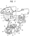
- Fig. 1 is a perspective view showing a main portion of an electric stapler.
- the electric stapler includes a driving mechanism for a driver, a cutting mechanism, and a clincher mechanism. Both the cutting mechanism for a driver and the clincher mechanism are disposed under the driver mechanism.
- the driver mechanism for a driver includes grooved cams 1 driven by an electric motor (not shown), drive links 2 which are swung as the grooved cams 1 are turned, a driver holder 4 supported by a coupling bar 3, which couples both leading ends of the drive links 2, and a driver 5 supported by the driver holder 4.
- the drive links 2 is swung and the driver 5 is vertically moved.
- a staple supplying device (not shown) for supplying staples is provided under the driver 5.
- a stapling table 7 on which a stapled object 15 is located is provided under the driver 5.
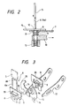
- a couple of clincher holders 8, while being spaced from each other, are located under the stapling table 7.
- the clincher holders 8 guide the leg portions 6a of a staple 6 which is driven out by the driver 5, while the clincher holders 8 holds a movable clincher to be described later.
- a cutting mechanism for staple legs is penetrating the clincher holders 8 and a clincher mechanism are disposed in the clincher holders 8.
- the cutting mechanism for staple legs includes a rectangular hole 9 laterally elongated in the clincher holder 8.
- a block-shaped cutter 10 is mounted and movable into and out of the rectangular hole 9.
- Leg receiving holes 11 are formed in the front portion of the cutter 10 so as to receive leg portions 6a of the staple 6.
- the leg receiving holes 11 are formed in a vertical direction and with elongated laterally.
- curved plates 14 are disposed under the cutter.
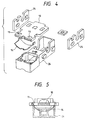
- the stapling table 7 includes an opening 12 defined by a couple of the clincher holders 8.
- the opening 12 is positioned where a staple 6 reaches when the driver 5 is downwardly driven and hits the staple 6.
- the leg portions 6a of the staple 6 pass a space defined between a couple of the clincher holders 8.
- a couple of movable clinchers 13 are rotatably arranged between the clincher holders 8.
- Each of movable clinchers 13 is arcuately curved so as to avoid the rectangular hole 9 of the clincher holders 8.
- the bases 13a of the movable clinchers 13 are overlapped each other and rotatably supported by a shaft 26.
- each leading end 13b is moved along the underside of the stapled object 15, and the movable clinchers 13 are opened and closed.
- Each of the movable clinchers 13 includes an engaging groove 16 which is formed in the outer edge at a lower position thereof.
- clincher levers 17 are respectively arranged under the movable clinchers 13, and are vertically movable.
- the clincher levers 17 are arranged in such a manner that the leading ends of the clincher levers 17 are engageable with engaging grooves 16 of the movable clincher 13.
- the clincher levers 17 are swingably supported at their central portion by a support shaft 19.
- the support shaft 19 is provided on a base table 18 integral with the stapling table 7 of the electric stapler.
- a drive link 20 is coupled with the rear portion of each of the clincher levers 17.
- Each rear end of the drive links 20 is engaged with a groove (not shown) formed on the rear side of the grooved cam 1.
- a triangular link plate 21 is located near each of clincher levers 17 and supported by a shaft 22 in a swingable fashion.
- the front end of the triangular link plate 21 is coupled with the corresponding clincher lever 17 by a shaft 26, and the upper end part thereof is coupled with the cutter 10 by a shaft 23.
- the drive links 2 is swung and then the driver 5 is vertically moved.
- the driver 5 When the driver 5 is downwardly driven, it hits the staple 6, and the leg portions 6a of the staple 6 pierce through the stapled object 15.
- the leg portions 6a of the staple 6, which have passed through the stapled object 15, are respectively inserted into the leg receiving holes 11 of the cutter 10, which is projected and located in front of the clincher holders. At this time, tips of the leg portions 6a abut against the curved plates 14 located thereunder, and the leg portions 6a are bent inward.
- the drive link 20 is similarly turned by the grooved cams 1 to move the clincher levers 17 upwardly.
- the link plates 21 are turned to retract the cutter 10, which has been located in front of the clincher holders.
- the cutter 10 cuts the unnecessary portions 25 of the leg portions 6a, as shown in Figs. 9(a) and 9(b).
- the front ends of the clincher levers 17 engage with the engaging grooves 16 of the movable clinchers 13 to push the movable clinchers 13 upwardly.
- the movable clinchers 13 turn in the closing direction about the shaft 26, to thereby bend the leg portions 6a of the staple 6 inward, as shown in Figs. 6A and 6B. Then the stapling operation of the electric stapler ends.
- the shape of the cutter for cutting the leg portions 6a is not limited to the planar shape as mentioned above. It may be V shaped as shown in Fig. 11A or U shaped as shown in Fig. 11B.
- the present invention is based on Japanese Patent Application No. Hei. 10-297005 which is incorporated herein by reference.
Landscapes
- Engineering & Computer Science (AREA)
- Mechanical Engineering (AREA)
- Life Sciences & Earth Sciences (AREA)
- Forests & Forestry (AREA)
- Portable Nailing Machines And Staplers (AREA)
- Dovetailed Work, And Nailing Machines And Stapling Machines For Wood (AREA)
Applications Claiming Priority (2)
| Application Number | Priority Date | Filing Date | Title |
|---|---|---|---|
| JP29700598 | 1998-10-19 | ||
| JP29700598A JP3539232B2 (ja) | 1998-10-19 | 1998-10-19 | 電動ホッチキスにおけるステープル脚部の切断機構 |
Publications (3)
| Publication Number | Publication Date |
|---|---|
| EP0995561A2 true EP0995561A2 (fr) | 2000-04-26 |
| EP0995561A3 EP0995561A3 (fr) | 2001-11-14 |
| EP0995561B1 EP0995561B1 (fr) | 2004-02-18 |
Family
ID=17841025
Family Applications (1)
| Application Number | Title | Priority Date | Filing Date |
|---|---|---|---|
| EP99120613A Expired - Lifetime EP0995561B1 (fr) | 1998-10-19 | 1999-10-18 | Mécanisme pour couper les branches des agrafes pour une agrafeuse électrique |
Country Status (4)
| Country | Link |
|---|---|
| US (1) | US6250531B1 (fr) |
| EP (1) | EP0995561B1 (fr) |
| JP (1) | JP3539232B2 (fr) |
| DE (1) | DE69914846T2 (fr) |
Cited By (8)
| Publication number | Priority date | Publication date | Assignee | Title |
|---|---|---|---|---|
| WO2003057417A1 (fr) * | 2002-01-11 | 2003-07-17 | Isaberg Rapid Ab | Agrafeuse dotee de bras de pliage qui coupent les branches de l'agrafe contre une cale |
| EP1683616A1 (fr) * | 2003-10-20 | 2006-07-26 | Max Co., Ltd. | Unite de coupe d'une agrafeuse |
| EP1704968A1 (fr) * | 2004-01-13 | 2006-09-27 | Max Co., Ltd. | Agrafeuse |
| EP1731268A1 (fr) * | 2005-06-09 | 2006-12-13 | Apex Mfg. Co., Ltd. | Agrafeuse capable de couper les branches des agrafes |
| EP1749619A1 (fr) * | 2004-05-27 | 2007-02-07 | Max Co., Ltd. | Dispositif de sertissage pour agrafeuse |
| EP1767314A1 (fr) * | 2004-07-15 | 2007-03-28 | Max Co., Ltd. | Agrafeuse |
| EP1834745A1 (fr) * | 2004-12-15 | 2007-09-19 | Max Co., Ltd. | Cartouche d'agrafes et dispositif de traitement de debris de coupe de pattes d'agrafe |
| EP3659766A1 (fr) * | 2018-11-02 | 2020-06-03 | Max Co., Ltd. | Agrafeuse |
Families Citing this family (16)
| Publication number | Priority date | Publication date | Assignee | Title |
|---|---|---|---|---|
| JP2002355804A (ja) * | 2001-05-31 | 2002-12-10 | Nisca Corp | ステープル装置 |
| JP4103765B2 (ja) * | 2003-10-20 | 2008-06-18 | マックス株式会社 | ステープラーのステープル脚切断機構 |
| US6942136B2 (en) * | 2003-10-21 | 2005-09-13 | Apex Mfg. Co., Ltd. | Stapler apparatus to staple stacks of paper with different thicknesses |
| JP4117485B2 (ja) * | 2004-01-13 | 2008-07-16 | マックス株式会社 | ステープラーの可動クリンチャ駆動機構 |
| JP4513442B2 (ja) * | 2004-07-20 | 2010-07-28 | マックス株式会社 | ステープラーのステープル脚切断屑処理装置 |
| US7108165B2 (en) * | 2004-12-08 | 2006-09-19 | Apex Mfg. Co., Ltd. | Stapler capable of cutting staple legs one after another |
| US6981626B1 (en) * | 2004-12-08 | 2006-01-03 | Apex Mfg. Co., Ltd. | Stapler with a leg-cutting device |
| US7334716B2 (en) * | 2005-01-26 | 2008-02-26 | Apex Mfg. Co., Ltd. | Stapler capable of cutting staple legs one after another |
| CA2595810A1 (fr) * | 2005-01-27 | 2006-08-03 | Acco Brands Usa Llc | Agrafeuse munie d'un systeme de compensation de la hauteur de la pile |
| US7311236B2 (en) * | 2005-04-25 | 2007-12-25 | Tsi Manufacturing Llc | Electric stapler having two anvil plates and workpiece sensing controller |
| US7159749B2 (en) * | 2005-05-31 | 2007-01-09 | Apex Mfg. Co., Ltd. | Stapler capable of cutting staple legs |
| JP2009226909A (ja) * | 2008-03-25 | 2009-10-08 | Max Co Ltd | 電動ステープラにおけるステープル脚の長さ調整方法 |
| JP5359694B2 (ja) * | 2008-10-17 | 2013-12-04 | マックス株式会社 | ステープラのクリンチャ機構 |
| US9015968B2 (en) * | 2012-07-06 | 2015-04-28 | Caterpillar Inc. | Thumb for an excavator machine with structure support |
| JP6870282B2 (ja) * | 2016-10-31 | 2021-05-12 | マックス株式会社 | ステープラ |
| CN113561277B (zh) * | 2021-06-07 | 2022-07-08 | 杭州亚太智能装备有限公司 | 一种气动码钉枪 |
Citations (4)
| Publication number | Priority date | Publication date | Assignee | Title |
|---|---|---|---|---|
| US4378085A (en) * | 1980-11-03 | 1983-03-29 | Xerox Corporation | Stapler apparatus having a mechanism for bending and cutting staple legs in accordance with the thickness of the work piece |
| EP0266700A2 (fr) * | 1986-10-31 | 1988-05-11 | Max Co., Ltd. | Dispositif pour la coupe des jambes d'une agrafe |
| JPH0428501A (ja) * | 1990-05-24 | 1992-01-31 | Nakabayashi Kk | コンピューター出力用紙専用綴じ機に於けるかしめ装置 |
| JPH10128683A (ja) * | 1996-10-29 | 1998-05-19 | Max Co Ltd | 電動ホッチキスのステープルの脚部切断機構 |
Family Cites Families (5)
| Publication number | Priority date | Publication date | Assignee | Title |
|---|---|---|---|---|
| US4644634A (en) * | 1984-07-30 | 1987-02-24 | Usm Corporation | Removable blades for cut-clinch head assembly |
| JPS6399904A (ja) * | 1986-10-16 | 1988-05-02 | マックス株式会社 | ホツチキスのステ−プル脚切断駆動装置 |
| JPH0616667Y2 (ja) * | 1987-03-10 | 1994-05-02 | 久夫 佐藤 | ステ−プラ− |
| US6059504A (en) * | 1997-07-03 | 2000-05-09 | Max Co., Ltd. | Binding device |
| JP3598765B2 (ja) * | 1997-09-24 | 2004-12-08 | マックス株式会社 | ホッチキスにおけるステープルのクリンチ機構 |
-
1998
- 1998-10-19 JP JP29700598A patent/JP3539232B2/ja not_active Expired - Fee Related
-
1999
- 1999-10-18 EP EP99120613A patent/EP0995561B1/fr not_active Expired - Lifetime
- 1999-10-18 DE DE69914846T patent/DE69914846T2/de not_active Expired - Lifetime
- 1999-10-19 US US09/420,800 patent/US6250531B1/en not_active Expired - Lifetime
Patent Citations (4)
| Publication number | Priority date | Publication date | Assignee | Title |
|---|---|---|---|---|
| US4378085A (en) * | 1980-11-03 | 1983-03-29 | Xerox Corporation | Stapler apparatus having a mechanism for bending and cutting staple legs in accordance with the thickness of the work piece |
| EP0266700A2 (fr) * | 1986-10-31 | 1988-05-11 | Max Co., Ltd. | Dispositif pour la coupe des jambes d'une agrafe |
| JPH0428501A (ja) * | 1990-05-24 | 1992-01-31 | Nakabayashi Kk | コンピューター出力用紙専用綴じ機に於けるかしめ装置 |
| JPH10128683A (ja) * | 1996-10-29 | 1998-05-19 | Max Co Ltd | 電動ホッチキスのステープルの脚部切断機構 |
Non-Patent Citations (2)
| Title |
|---|
| PATENT ABSTRACTS OF JAPAN vol. 016, no. 195 (M-1246), 12 May 1992 (1992-05-12) & JP 04 028501 A (NAKABAYASHI KK), 31 January 1992 (1992-01-31) * |
| PATENT ABSTRACTS OF JAPAN vol. 1998, no. 10, 31 August 1998 (1998-08-31) -& JP 10 128683 A (MAX CO LTD), 19 May 1998 (1998-05-19) * |
Cited By (17)
| Publication number | Priority date | Publication date | Assignee | Title |
|---|---|---|---|---|
| US7021515B2 (en) | 2002-01-11 | 2006-04-04 | Isaberg Rapid Ab | Stapler with bending arms which cut the staple legs against a pad |
| US7195141B2 (en) | 2002-01-11 | 2007-03-27 | Isaberg Rapid Ab | Stapler with bending arms which cut the staple legs against a pad |
| WO2003057417A1 (fr) * | 2002-01-11 | 2003-07-17 | Isaberg Rapid Ab | Agrafeuse dotee de bras de pliage qui coupent les branches de l'agrafe contre une cale |
| EP1683616A1 (fr) * | 2003-10-20 | 2006-07-26 | Max Co., Ltd. | Unite de coupe d'une agrafeuse |
| EP1683616A4 (fr) * | 2003-10-20 | 2008-07-30 | Max Co Ltd | Unite de coupe d'une agrafeuse |
| EP1704968A1 (fr) * | 2004-01-13 | 2006-09-27 | Max Co., Ltd. | Agrafeuse |
| EP1704968A4 (fr) * | 2004-01-13 | 2008-08-13 | Max Co Ltd | Agrafeuse |
| EP1749619A4 (fr) * | 2004-05-27 | 2009-06-10 | Max Co Ltd | Dispositif de sertissage pour agrafeuse |
| EP1749619A1 (fr) * | 2004-05-27 | 2007-02-07 | Max Co., Ltd. | Dispositif de sertissage pour agrafeuse |
| EP1767314A4 (fr) * | 2004-07-15 | 2009-11-11 | Max Co Ltd | Agrafeuse |
| EP1767314A1 (fr) * | 2004-07-15 | 2007-03-28 | Max Co., Ltd. | Agrafeuse |
| EP1834745A1 (fr) * | 2004-12-15 | 2007-09-19 | Max Co., Ltd. | Cartouche d'agrafes et dispositif de traitement de debris de coupe de pattes d'agrafe |
| EP1834745A4 (fr) * | 2004-12-15 | 2009-05-13 | Max Co Ltd | Cartouche d'agrafes et dispositif de traitement de debris de coupe de pattes d'agrafe |
| US7922056B2 (en) | 2004-12-15 | 2011-04-12 | Max Co., Ltd. | Staple cartridge and staple leg chip processing apparatus |
| EP1731268A1 (fr) * | 2005-06-09 | 2006-12-13 | Apex Mfg. Co., Ltd. | Agrafeuse capable de couper les branches des agrafes |
| EP3659766A1 (fr) * | 2018-11-02 | 2020-06-03 | Max Co., Ltd. | Agrafeuse |
| US11376723B2 (en) | 2018-11-02 | 2022-07-05 | Max Co., Ltd. | Stapler |
Also Published As
| Publication number | Publication date |
|---|---|
| DE69914846D1 (de) | 2004-03-25 |
| JP2000127062A (ja) | 2000-05-09 |
| US6250531B1 (en) | 2001-06-26 |
| DE69914846T2 (de) | 2004-07-08 |
| EP0995561B1 (fr) | 2004-02-18 |
| EP0995561A3 (fr) | 2001-11-14 |
| JP3539232B2 (ja) | 2004-07-07 |
Similar Documents
| Publication | Publication Date | Title |
|---|---|---|
| US6250531B1 (en) | Staple leg cutting mechanism for an electric stapler | |
| EP0904904B1 (fr) | Dispositif de repliage pour agrafeuse | |
| EP2070658B1 (fr) | Agrafeuse | |
| EP1736282B1 (fr) | Agrafeuse | |
| US4288018A (en) | Fastening device for papers | |
| EP2236257B1 (fr) | Appareil de traitement de plaque | |
| US6942136B2 (en) | Stapler apparatus to staple stacks of paper with different thicknesses | |
| JP4713503B2 (ja) | ホッチキス | |
| JP4082251B2 (ja) | ステープラーのクリンチャ装置 | |
| EP0027336A1 (fr) | Enclume et agrafeuse la comportant | |
| JP4103765B2 (ja) | ステープラーのステープル脚切断機構 | |
| EP1220737B1 (fr) | Agrafeuse destinee a former des agrafes de tailles differentes | |
| KR101036389B1 (ko) | 카트리지 | |
| JP2004230483A (ja) | ホッチキス | |
| EP1683616B1 (fr) | Unite de coupe d'une agrafeuse | |
| WO2005068135A1 (fr) | Agrafeuse | |
| JP3503368B2 (ja) | 電動ホッチキスのステープルの脚部切断機構 | |
| US7621434B2 (en) | Clincher device of stapler | |
| EP1599317B1 (fr) | Magasin a agrafes amovible equipe d'une forme a agrafes amovible | |
| JP4117485B2 (ja) | ステープラーの可動クリンチャ駆動機構 | |
| EP1787759B1 (fr) | Agrafeuse | |
| JP4093155B2 (ja) | ステープラー用のクリンチャ装置 | |
| JPH09109062A (ja) | ステープラ | |
| JP2554548Y2 (ja) | スティプラ | |
| GB2408477A (en) | Stapler |
Legal Events
| Date | Code | Title | Description |
|---|---|---|---|
| PUAI | Public reference made under article 153(3) epc to a published international application that has entered the european phase |
Free format text: ORIGINAL CODE: 0009012 |
|
| AK | Designated contracting states |
Kind code of ref document: A2 Designated state(s): AT BE CH CY DE DK ES FI FR GB GR IE IT LI LU MC NL PT SE Kind code of ref document: A2 Designated state(s): DE FR GB NL SE |
|
| AX | Request for extension of the european patent |
Free format text: AL;LT;LV;MK;RO;SI |
|
| PUAL | Search report despatched |
Free format text: ORIGINAL CODE: 0009013 |
|
| AK | Designated contracting states |
Kind code of ref document: A3 Designated state(s): AT BE CH CY DE DK ES FI FR GB GR IE IT LI LU MC NL PT SE |
|
| AX | Request for extension of the european patent |
Free format text: AL;LT;LV;MK;RO;SI |
|
| 17P | Request for examination filed |
Effective date: 20011220 |
|
| AKX | Designation fees paid |
Free format text: DE FR GB NL SE |
|
| GRAP | Despatch of communication of intention to grant a patent |
Free format text: ORIGINAL CODE: EPIDOSNIGR1 |
|
| GRAS | Grant fee paid |
Free format text: ORIGINAL CODE: EPIDOSNIGR3 |
|
| GRAA | (expected) grant |
Free format text: ORIGINAL CODE: 0009210 |
|
| AK | Designated contracting states |
Kind code of ref document: B1 Designated state(s): DE FR GB NL SE |
|
| REG | Reference to a national code |
Ref country code: GB Ref legal event code: FG4D |
|
| REF | Corresponds to: |
Ref document number: 69914846 Country of ref document: DE Date of ref document: 20040325 Kind code of ref document: P |
|
| ET | Fr: translation filed | ||
| PLBE | No opposition filed within time limit |
Free format text: ORIGINAL CODE: 0009261 |
|
| STAA | Information on the status of an ep patent application or granted ep patent |
Free format text: STATUS: NO OPPOSITION FILED WITHIN TIME LIMIT |
|
| 26N | No opposition filed |
Effective date: 20041119 |
|
| REG | Reference to a national code |
Ref country code: FR Ref legal event code: PLFP Year of fee payment: 18 |
|
| PGFP | Annual fee paid to national office [announced via postgrant information from national office to epo] |
Ref country code: NL Payment date: 20160913 Year of fee payment: 18 |
|
| PGFP | Annual fee paid to national office [announced via postgrant information from national office to epo] |
Ref country code: FR Payment date: 20160919 Year of fee payment: 18 |
|
| PGFP | Annual fee paid to national office [announced via postgrant information from national office to epo] |
Ref country code: DE Payment date: 20161011 Year of fee payment: 18 Ref country code: GB Payment date: 20161012 Year of fee payment: 18 |
|
| PGFP | Annual fee paid to national office [announced via postgrant information from national office to epo] |
Ref country code: SE Payment date: 20161011 Year of fee payment: 18 |
|
| REG | Reference to a national code |
Ref country code: DE Ref legal event code: R119 Ref document number: 69914846 Country of ref document: DE |
|
| REG | Reference to a national code |
Ref country code: SE Ref legal event code: EUG |
|
| REG | Reference to a national code |
Ref country code: NL Ref legal event code: MM Effective date: 20171101 |
|
| GBPC | Gb: european patent ceased through non-payment of renewal fee |
Effective date: 20171018 |
|
| REG | Reference to a national code |
Ref country code: FR Ref legal event code: ST Effective date: 20180629 |
|
| PG25 | Lapsed in a contracting state [announced via postgrant information from national office to epo] |
Ref country code: DE Free format text: LAPSE BECAUSE OF NON-PAYMENT OF DUE FEES Effective date: 20180501 Ref country code: NL Free format text: LAPSE BECAUSE OF NON-PAYMENT OF DUE FEES Effective date: 20171101 Ref country code: GB Free format text: LAPSE BECAUSE OF NON-PAYMENT OF DUE FEES Effective date: 20171018 |
|
| PG25 | Lapsed in a contracting state [announced via postgrant information from national office to epo] |
Ref country code: SE Free format text: LAPSE BECAUSE OF NON-PAYMENT OF DUE FEES Effective date: 20171019 Ref country code: FR Free format text: LAPSE BECAUSE OF NON-PAYMENT OF DUE FEES Effective date: 20171031 |