EP0993344B2 - Transducteur ultrasonore - Google Patents
Transducteur ultrasonore Download PDFInfo
- Publication number
- EP0993344B2 EP0993344B2 EP98941228A EP98941228A EP0993344B2 EP 0993344 B2 EP0993344 B2 EP 0993344B2 EP 98941228 A EP98941228 A EP 98941228A EP 98941228 A EP98941228 A EP 98941228A EP 0993344 B2 EP0993344 B2 EP 0993344B2
- Authority
- EP
- European Patent Office
- Prior art keywords
- ultrasonic transducer
- wall
- transducer according
- housing
- vibrational
- Prior art date
- Legal status (The legal status is an assumption and is not a legal conclusion. Google has not performed a legal analysis and makes no representation as to the accuracy of the status listed.)
- Expired - Lifetime
Links
- 230000000087 stabilizing effect Effects 0.000 claims description 11
- 239000000463 material Substances 0.000 claims description 2
- 238000009434 installation Methods 0.000 description 6
- 239000012528 membrane Substances 0.000 description 4
- 230000001419 dependent effect Effects 0.000 description 2
- 238000004519 manufacturing process Methods 0.000 description 2
- 230000005855 radiation Effects 0.000 description 2
- 238000004026 adhesive bonding Methods 0.000 description 1
- 230000002411 adverse Effects 0.000 description 1
- 230000000052 comparative effect Effects 0.000 description 1
- 238000010276 construction Methods 0.000 description 1
- 239000013078 crystal Substances 0.000 description 1
- 238000013016 damping Methods 0.000 description 1
- 238000005259 measurement Methods 0.000 description 1
- 238000013160 medical therapy Methods 0.000 description 1
Images

Classifications
-
- G—PHYSICS
- G10—MUSICAL INSTRUMENTS; ACOUSTICS
- G10K—SOUND-PRODUCING DEVICES; METHODS OR DEVICES FOR PROTECTING AGAINST, OR FOR DAMPING, NOISE OR OTHER ACOUSTIC WAVES IN GENERAL; ACOUSTICS NOT OTHERWISE PROVIDED FOR
- G10K9/00—Devices in which sound is produced by vibrating a diaphragm or analogous element, e.g. fog horns, vehicle hooters or buzzers
- G10K9/12—Devices in which sound is produced by vibrating a diaphragm or analogous element, e.g. fog horns, vehicle hooters or buzzers electrically operated
- G10K9/122—Devices in which sound is produced by vibrating a diaphragm or analogous element, e.g. fog horns, vehicle hooters or buzzers electrically operated using piezoelectric driving means
-
- G—PHYSICS
- G10—MUSICAL INSTRUMENTS; ACOUSTICS
- G10K—SOUND-PRODUCING DEVICES; METHODS OR DEVICES FOR PROTECTING AGAINST, OR FOR DAMPING, NOISE OR OTHER ACOUSTIC WAVES IN GENERAL; ACOUSTICS NOT OTHERWISE PROVIDED FOR
- G10K11/00—Methods or devices for transmitting, conducting or directing sound in general; Methods or devices for protecting against, or for damping, noise or other acoustic waves in general
- G10K11/004—Mounting transducers, e.g. provided with mechanical moving or orienting device
-
- G—PHYSICS
- G10—MUSICAL INSTRUMENTS; ACOUSTICS
- G10K—SOUND-PRODUCING DEVICES; METHODS OR DEVICES FOR PROTECTING AGAINST, OR FOR DAMPING, NOISE OR OTHER ACOUSTIC WAVES IN GENERAL; ACOUSTICS NOT OTHERWISE PROVIDED FOR
- G10K11/00—Methods or devices for transmitting, conducting or directing sound in general; Methods or devices for protecting against, or for damping, noise or other acoustic waves in general
- G10K11/18—Methods or devices for transmitting, conducting or directing sound
- G10K11/26—Sound-focusing or directing, e.g. scanning
-
- G—PHYSICS
- G01—MEASURING; TESTING
- G01S—RADIO DIRECTION-FINDING; RADIO NAVIGATION; DETERMINING DISTANCE OR VELOCITY BY USE OF RADIO WAVES; LOCATING OR PRESENCE-DETECTING BY USE OF THE REFLECTION OR RERADIATION OF RADIO WAVES; ANALOGOUS ARRANGEMENTS USING OTHER WAVES
- G01S7/00—Details of systems according to groups G01S13/00, G01S15/00, G01S17/00
- G01S7/52—Details of systems according to groups G01S13/00, G01S15/00, G01S17/00 of systems according to group G01S15/00
- G01S7/521—Constructional features
Definitions
- the invention relates to an ultrasonic transducer with a pot-like housing according to the preamble of the main claim.
- An ultrasonic transducer is already known which has a cup-shaped housing. On the inside of a piezoceramic vibrating element is applied to the bottom of the pot. In order to dampen harmonics and to form the propagation or reception lobe of this arrangement, on the inside of the cup-shaped converter housing on two opposite sides of the circular segment-shaped damping body are mounted. For attachment of the ultrasonic transducer is placed in a housing made of soft plastic or soft rubber.
- Unfavorable in this construction is that not only the membrane, but also the housing wall is excited to vibrate by the uniform wall thickness of the cup-shaped housing, so that both the transmitting and the receiving lobe is adversely affected by superposition of harmonics or extinguished.
- an ultrasonic transducer with an asymmetrical radiation characteristic is known.
- parallel to the bottom surface fan-shaped radiation characteristic is taken out of the membrane-side end of the converter pot in the installation direction top and bottom each have a segment-shaped piece or formed a recess in the membrane.
- an ultrasonic transducer for medical therapy is known, wherein on the transducer pot a thread is arranged, with which the ultrasonic transducer can be attached to a handle.
- a piezoelectric crystal for vibration generation is arranged on the opposite side of a front surface.
- an electroacoustic transducer in which a vibrating diaphragm is disposed in a circular opening of a fixed housing. Due to the design of the vibration diaphragm, the emission characteristic of the electroacoustic transducer is determined.
- the ultrasonic transducer according to the invention with the characterizing features of the main claim has the advantage that a greater rigidity of the housing is achieved by the stabilizing ring on the wall of the pot-like housing, so that the remaining part of the bottom surface of the housing acts as a vibrating diaphragm, preferably on the fundamental shaft swings. It is particularly advantageous that because of the greater mass of the wall and the Nachschwingdauer the vibrating diaphragm is shortened, so that advantageously results in a better overall propagation and reception lobe, as well as a better vibration behavior. In particular, by the shortened Nachschwingdauer a distance measurement, as they are still performed for example in a parking aid of a motor vehicle at very small distances to the obstacle.
- the stabilizing ring is already formed in the manufacture of the housing, so that the production costs are relatively low.
- a sound funnel is arranged on the outside of the wall in the region of the vibration membrane.
- the horn is designed as a ring and surrounds the vibrating diaphragm.
- the range of the ultrasonic transducer can be specified.
- the sound converter is flush with the plane of the vibrating diaphragm. In an alternative embodiment, however, it is also cone-shaped in order to influence the propagation and reception lobe of the ultrasonic waves even more. In order to create better installation conditions, it is envisaged to form the cross-section of the sound director either rectangular or conical.
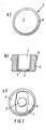
- FIGS. 1a, b, c show different views of a first embodiment
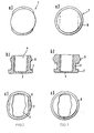
- FIGS. 2a, b, c show a second embodiment
- the FIGS. 3a, b, c show a third embodiment
- the FIGS. 4a, b, c show a fourth embodiment
- the FIGS. 5a, b, c show a fifth embodiment.
- FIG. 1a an ultrasonic transducer 1 in plan view. Visible, noticeable is the bottom of the pot, which is designed as a vibrating diaphragm 3. On the outer wall a stabilizing ring 6 is annularly arranged.
- FIG. 1b shows a sectional view in which the ultrasonic transducer 1 is shown in cross section. Visible is a pot-like housing with a relatively thick wall 2, the vibrating diaphragm 3 as a pot bottom and with the stabilizing ring 6. On the inside is on the bottom of the pot, a vibrating element 5, preferably applied by gluing, so that it has a good mechanical contact with the vibrating diaphragm 3 , The interior of the housing is referred to as recess 4.
- Figure c shows a rear plan view into the housing.
- the recess 4 has an approximately rectangular cross-sectional area, which limits the vibrating diaphragm 3 at the same time.
- electrical supply lines to the oscillating element 5 have been omitted in order to maintain clarity.
- the stabilizing ring 6 In the second embodiment according to the Figures 2a-c it is proposed to form the stabilizing ring 6 approximately oval in approximately parallel to the cross-sectional area of the recess 4.
- the wall 2 is thus formed approximately rectangular in the rear part, while in the region of the vibrating diaphragm 3, however, is circular.
- the circular structure forms a sound converter 7, which causes a limitation of the sound waves.
- the sounder 7 is formed flush with the outer surface of the vibrating diaphragm 3 and is rectangular in cross-section.
- the dimensions of the individual elements are on the one hand dependent on the working frequency, on the other hand on the available installation dimensions, for example in the bumper of a motor vehicle. The individual dimensions are expediently determined by comparative experiments.
- the embodiments according to the Figures 3 - 5 are from the embodiment according to the FIG. 2 derived.
- the third embodiment largely corresponds to the second embodiment.
- the recess 4 is made approximately rectangular.
- the stabilizing ring is, however, rotationally symmetrical in shape and formed much stronger than in the second embodiment ( FIG. 3b ).
- the fourth embodiment according to the FIGS. 4a-c differs from the third embodiment, essentially by the constriction of the wall 2.
- the acoustic funnel 7 is formed conically on its back. As a result, an acoustic decoupling of the rear pot area from the oscillating membrane is partially achieved.
- the sounder 7 is conically formed on the outer base, so that it forms a small funnel in conjunction with the vibrating diaphragm 3.
- the propagation and reception lobe is even more malleable.
- the mass of unwanted resonant material so that the decay time (Nachschwingzeit) of the ultrasonic transducer is reduced after switching off the exciter pulse. This has the consequence that the smallest measurable distance compared to known ultrasonic sensors is smaller, so that this sensor is particularly suitable for installation in a parking aid, since with him and tight space conditions are advantageously detectable.
Landscapes
- Physics & Mathematics (AREA)
- Engineering & Computer Science (AREA)
- Acoustics & Sound (AREA)
- Multimedia (AREA)
- Transducers For Ultrasonic Waves (AREA)
- Measurement Of Velocity Or Position Using Acoustic Or Ultrasonic Waves (AREA)
- Separation Using Semi-Permeable Membranes (AREA)
Claims (8)
- Transducteur d'ultrasons comportant un boîtier en forme de pot avec une paroi annulaire et une surface de fond comme membrane vibrante,
un élément piézoélectrique étant installé comme élément vibrant sur le côté intérieur de la surface du fond,
la paroi (2) ayant des épaisseurs différentes, et
seulement une partie de la surface extérieure du fond fonctionnant comme membrane vibrante (3),
caractérisé en ce que
un anneau de stabilisation (6) est prévu sur le côté extérieur de la paroi (2) du transducteur d'ultrasons (1) et
le transducteur (1) comporte une cavité (4) ayant une section à peu près rectangulaire. - Transducteur d'ultrasons selon la revendication 1,
caractérisé en ce que
l'anneau de stabilisation (6) est prévu sur la paroi (2), dans une position éloignée de la membrane vibrante (3). - Transducteur d'ultrasons selon les revendications 1 ou 2,
caractérisé en ce que
l'anneau de stabilisation (6) est réalisé dans la matière du boîtier. - Transducteur d'ultrasons selon l'une des revendications précédentes,
caractérisé par
un redresseur de son (7) au niveau de la membrane vibrante (3), sur le côté extérieur de la paroi (2). - Transducteur d'ultrasons selon la revendication 4,
caractérisé en ce que
le redresseur de son (7) est en forme d'anneau entourant la membrane vibrante (3). - Transducteur d'ultrasons selon les revendications 4 ou 5,
caractérisé en ce que
le redresseur (7) est à fleur avec la membrane vibrante (3). - Transducteur d'ultrasons selon les revendications 4 ou 5,
caractérisé en ce que
le redresseur (7) forme une trémie avec la membrane vibrante (3). - Transducteur d'ultrasons selon les revendications 4 à 7,
caractérisé en ce que
le redresseur de son (7) est en forme de cône par rapport à la paroi (2) et rétrécit la paroi (2).
Applications Claiming Priority (3)
| Application Number | Priority Date | Filing Date | Title |
|---|---|---|---|
| DE19727877A DE19727877A1 (de) | 1997-06-30 | 1997-06-30 | Ultraschallwandler |
| DE19727877 | 1997-06-30 | ||
| PCT/DE1998/001734 WO1999001234A2 (fr) | 1997-06-30 | 1998-06-25 | Transducteur ultrasonore |
Publications (3)
| Publication Number | Publication Date |
|---|---|
| EP0993344A2 EP0993344A2 (fr) | 2000-04-19 |
| EP0993344B1 EP0993344B1 (fr) | 2003-01-29 |
| EP0993344B2 true EP0993344B2 (fr) | 2008-10-15 |
Family
ID=7834178
Family Applications (1)
| Application Number | Title | Priority Date | Filing Date |
|---|---|---|---|
| EP98941228A Expired - Lifetime EP0993344B2 (fr) | 1997-06-30 | 1998-06-25 | Transducteur ultrasonore |
Country Status (5)
| Country | Link |
|---|---|
| US (1) | US6465935B1 (fr) |
| EP (1) | EP0993344B2 (fr) |
| JP (1) | JP4263251B2 (fr) |
| DE (2) | DE19727877A1 (fr) |
| WO (1) | WO1999001234A2 (fr) |
Families Citing this family (17)
| Publication number | Priority date | Publication date | Assignee | Title |
|---|---|---|---|---|
| JP3324593B2 (ja) | 1999-10-28 | 2002-09-17 | 株式会社村田製作所 | 超音波振動装置 |
| JP3972610B2 (ja) * | 2001-07-26 | 2007-09-05 | 松下電工株式会社 | 超音波美容器 |
| DE10136628B4 (de) * | 2001-07-26 | 2006-04-20 | Valeo Schalter Und Sensoren Gmbh | Ultraschallwandler zum Aussenden und Empfangen von Ultraschallwellen mittels einer Membran, Verfahren und Steuergerät zum Betrieb des Ultraschallwandlers, sowie Verwendung des Ultraschallwandlers |
| DE10304001A1 (de) * | 2003-02-01 | 2004-08-12 | Valeo Schalter Und Sensoren Gmbh | Topfförmige Menbrane für einen Sensor, insbesondere einen Ultraschallsensor und Sensor, insbesondere Ultraschallsensor |
| JP2007114182A (ja) * | 2005-09-22 | 2007-05-10 | Denso Corp | 超音波センサの取付け構造 |
| DE102005046173A1 (de) * | 2005-09-27 | 2007-04-05 | Siemens Ag | Ultraschallwandler für verdeckten Einbau |
| EP1906383B1 (fr) * | 2006-09-29 | 2013-11-13 | Tung Thih Electronic Co., Ltd. | Appareil de transducteur à ultrasons |
| DE102006050037A1 (de) * | 2006-10-24 | 2008-04-30 | Robert Bosch Gmbh | Ultraschallwandler |
| ITMO20070377A1 (it) * | 2007-12-07 | 2009-06-08 | Meta System Spa | Dispositivo per il rilevamento di oggetti in prossimita' di veicoli, impiegabile in particolare in sistemi di assistenza al parcheggio o simili |
| DE102008040905A1 (de) * | 2008-07-31 | 2010-02-04 | Robert Bosch Gmbh | Ultraschallsensor |
| DE102011004845A1 (de) | 2011-02-28 | 2012-08-30 | BSH Bosch und Siemens Hausgeräte GmbH | Kolbenverdichter und Kältegerät mit einem Kolbenverdichter |
| DE102012209238A1 (de) * | 2012-05-31 | 2013-12-05 | Robert Bosch Gmbh | Ultraschallsensor sowie Vorrichtung und Verfahren zur Messung eines Abstands zwischen einem Fahrzeug und einem Hindernis |
| DE102012109838A1 (de) * | 2012-10-16 | 2014-04-17 | Volkswagen Ag | Ultraschallsensorvorrichtung mit einer Versteifungseinheit, Anordnung, Kraftfahrzeug und Verfahren zum Herstellen einer Anordnung |
| DE102017223089A1 (de) | 2017-12-18 | 2019-06-19 | Robert Bosch Gmbh | Sensoranordnung zum Senden und/oder Empfangen eines Schallsignals |
| US12207054B2 (en) | 2018-10-24 | 2025-01-21 | Cochlear Limited | Implantable transducer with integrated diaphragm |
| DE102021133906A1 (de) * | 2021-12-20 | 2023-06-22 | Tdk Electronics Ag | Ultraschallwandler mit Gehäuse |
| DE102024108606A1 (de) | 2024-03-26 | 2025-10-02 | Valeo Schalter Und Sensoren Gmbh | Ultraschallsensorvorrichtung für ein Fahrzeug sowie Verfahren zum Betreiben einer Ultraschallsensorvorrichtung |
Citations (6)
| Publication number | Priority date | Publication date | Assignee | Title |
|---|---|---|---|---|
| US3890423A (en) † | 1973-07-27 | 1975-06-17 | Nusonics | Electroacoustic transducer assembly |
| EP0075302A1 (fr) † | 1981-09-23 | 1983-03-30 | Egon Gelhard | Dispositif pour mesurer des distances au moyen d'échos ultrasonores |
| EP0283823A1 (fr) † | 1987-03-20 | 1988-09-28 | Siemens Aktiengesellschaft | Appareil pour la génération et le rayonnement d'ultrasons, en particulier pour la thérapie à ultrasons |
| DE3941933A1 (de) † | 1989-12-19 | 1991-06-20 | Siemens Ag | Ultraschallwandler fuer luftstroemungsmessung insbesondere zur luftmengenmessung bei verbrennungsmotoren |
| DE4120681A1 (de) † | 1990-08-04 | 1992-02-06 | Bosch Gmbh Robert | Ultraschallwandler |
| DE4215271A1 (de) † | 1992-05-09 | 1993-11-11 | Tridelta Ag | Ultraschallwandler |
Family Cites Families (12)
| Publication number | Priority date | Publication date | Assignee | Title |
|---|---|---|---|---|
| DE351626C (de) | 1918-02-23 | 1922-04-15 | Signal Ges M B H | Einrichtung zur UEbertragung und Aufnahme von Schallwellen in Fluessigkeiten |
| US3638052A (en) * | 1969-09-22 | 1972-01-25 | Dynamics Corp America | Electroacoustic transducers of the bilaminar flexural vibrating type |
| US3943388A (en) * | 1974-06-27 | 1976-03-09 | Fred M. Dellorfano, Jr. | Electroacoustic transducer of the flexural vibrating diaphragm type |
| US4607186A (en) | 1981-11-17 | 1986-08-19 | Matsushita Electric Industrial Co. Ltd. | Ultrasonic transducer with a piezoelectric element |
| DE3324575C2 (de) | 1982-07-22 | 1985-06-27 | Siemens AG, 1000 Berlin und 8000 München | Behandlungskopf zur therapeutischen Applikation von Ultraschall |
| DE3441684A1 (de) * | 1984-11-15 | 1986-05-15 | SWF Auto-Electric GmbH, 7120 Bietigheim-Bissingen | Elektroakustischer wandler |
| US4823042A (en) * | 1986-07-18 | 1989-04-18 | Rich-Mar Corporation | Sonic transducer and method for making the same |
| DE3732412A1 (de) * | 1987-09-25 | 1989-04-13 | Siemens Ag | Ultraschallwandler mit astigmatischer sende-/empfangscharakteristik |
| DE4413894C2 (de) * | 1994-04-21 | 2002-12-12 | Teves Gmbh Alfred | Biegewandler in Topfform |
| DE19527018C1 (de) * | 1995-07-24 | 1997-02-20 | Siemens Ag | Ultraschallwandler |
| DE19630350C2 (de) * | 1996-07-26 | 1998-08-20 | Siemens Ag | Ultraschallwandler |
| JP3721798B2 (ja) * | 1998-01-13 | 2005-11-30 | 株式会社村田製作所 | 超音波センサ |
-
1997
- 1997-06-30 DE DE19727877A patent/DE19727877A1/de not_active Withdrawn
-
1998
- 1998-06-25 EP EP98941228A patent/EP0993344B2/fr not_active Expired - Lifetime
- 1998-06-25 DE DE59807074T patent/DE59807074D1/de not_active Expired - Lifetime
- 1998-06-25 US US09/462,003 patent/US6465935B1/en not_active Expired - Lifetime
- 1998-06-25 WO PCT/DE1998/001734 patent/WO1999001234A2/fr not_active Ceased
- 1998-06-25 JP JP50609599A patent/JP4263251B2/ja not_active Expired - Lifetime
Patent Citations (6)
| Publication number | Priority date | Publication date | Assignee | Title |
|---|---|---|---|---|
| US3890423A (en) † | 1973-07-27 | 1975-06-17 | Nusonics | Electroacoustic transducer assembly |
| EP0075302A1 (fr) † | 1981-09-23 | 1983-03-30 | Egon Gelhard | Dispositif pour mesurer des distances au moyen d'échos ultrasonores |
| EP0283823A1 (fr) † | 1987-03-20 | 1988-09-28 | Siemens Aktiengesellschaft | Appareil pour la génération et le rayonnement d'ultrasons, en particulier pour la thérapie à ultrasons |
| DE3941933A1 (de) † | 1989-12-19 | 1991-06-20 | Siemens Ag | Ultraschallwandler fuer luftstroemungsmessung insbesondere zur luftmengenmessung bei verbrennungsmotoren |
| DE4120681A1 (de) † | 1990-08-04 | 1992-02-06 | Bosch Gmbh Robert | Ultraschallwandler |
| DE4215271A1 (de) † | 1992-05-09 | 1993-11-11 | Tridelta Ag | Ultraschallwandler |
Also Published As
| Publication number | Publication date |
|---|---|
| WO1999001234A3 (fr) | 1999-04-22 |
| JP2002507370A (ja) | 2002-03-05 |
| EP0993344A2 (fr) | 2000-04-19 |
| DE19727877A1 (de) | 1999-01-07 |
| JP4263251B2 (ja) | 2009-05-13 |
| WO1999001234A2 (fr) | 1999-01-14 |
| EP0993344B1 (fr) | 2003-01-29 |
| DE59807074D1 (de) | 2003-03-06 |
| US6465935B1 (en) | 2002-10-15 |
Similar Documents
| Publication | Publication Date | Title |
|---|---|---|
| EP0993344B2 (fr) | Transducteur ultrasonore | |
| DE2937942C2 (de) | Ultraschallwandler | |
| EP2856206B1 (fr) | Capteur à ultrasons ainsi que dispositif et procédé pour mesurer une distance entre un véhicule et un obstacle | |
| DE4238924A1 (de) | Elektroakustischer Wandler | |
| DE102007045809A1 (de) | Detektorvorrichtung für ein Hindernis | |
| EP0507892B1 (fr) | Transducteur ultrasonore | |
| DE19917862B4 (de) | Ultraschallsensor | |
| DE2541492C3 (de) | Ultraschallwandler | |
| DE19857024B4 (de) | Lautsprecher | |
| DE19832072B4 (de) | Piezoelektrischer elektroakustischer Konverter | |
| EP2660627B1 (fr) | Ensemble de détection comprenant un composant de véhicule plat et un capteur à ultrasons | |
| DE102008040905A1 (de) | Ultraschallsensor | |
| EP0802521A2 (fr) | Transducteur pour l'emission et/ou la réception des signaux acoustiques | |
| DE102013211606A1 (de) | Umfeldsensiereinrichtung mit Ultraschallwandler, und Kraftfahrzeug mit einer derartigen Umfeldsensiereinrichtung | |
| DE102017108341B4 (de) | Ultraschallsensorvorrichtung für ein Kraftfahrzeug mit einer Sendeeinrichtung und separaten Empfangseinrichtungen, Fahrerassistenzsystem sowie Kraftfahrzeug | |
| DE112021002364T5 (de) | Ultraschallsensor | |
| DE112020002082B4 (de) | Ultraschallsensor | |
| EP3010653B1 (fr) | Convertisseur électroacoustique | |
| DE4114180C2 (de) | Ultraschallwandler | |
| DE19912772C2 (de) | Ultraschallsensor zur Abstandsmessung | |
| DE2944998A1 (de) | Hornanordnung mit einem elektroakustischen wandler | |
| DE102017209823A1 (de) | Ultraschallsensor | |
| DE19754891C1 (de) | Ultraschallwandler | |
| DE1167076B (de) | Mechanische Impedanzanpassresonatorvorrichtung | |
| DE10009129A1 (de) | Ultraschallsensor |
Legal Events
| Date | Code | Title | Description |
|---|---|---|---|
| PUAI | Public reference made under article 153(3) epc to a published international application that has entered the european phase |
Free format text: ORIGINAL CODE: 0009012 |
|
| 17P | Request for examination filed |
Effective date: 20000131 |
|
| AK | Designated contracting states |
Kind code of ref document: A2 Designated state(s): DE FR GB IT SE |
|
| 17Q | First examination report despatched |
Effective date: 20001228 |
|
| GRAG | Despatch of communication of intention to grant |
Free format text: ORIGINAL CODE: EPIDOS AGRA |
|
| GRAG | Despatch of communication of intention to grant |
Free format text: ORIGINAL CODE: EPIDOS AGRA |
|
| GRAH | Despatch of communication of intention to grant a patent |
Free format text: ORIGINAL CODE: EPIDOS IGRA |
|
| GRAH | Despatch of communication of intention to grant a patent |
Free format text: ORIGINAL CODE: EPIDOS IGRA |
|
| GRAA | (expected) grant |
Free format text: ORIGINAL CODE: 0009210 |
|
| AK | Designated contracting states |
Designated state(s): DE FR GB IT SE |
|
| REG | Reference to a national code |
Ref country code: GB Ref legal event code: FG4D Free format text: NOT ENGLISH |
|
| REF | Corresponds to: |
Ref document number: 59807074 Country of ref document: DE Date of ref document: 20030306 Kind code of ref document: P |
|
| REG | Reference to a national code |
Ref country code: SE Ref legal event code: TRGR |
|
| GBT | Gb: translation of ep patent filed (gb section 77(6)(a)/1977) |
Effective date: 20030509 |
|
| ET | Fr: translation filed | ||
| PLBQ | Unpublished change to opponent data |
Free format text: ORIGINAL CODE: EPIDOS OPPO |
|
| PLBI | Opposition filed |
Free format text: ORIGINAL CODE: 0009260 |
|
| PLAX | Notice of opposition and request to file observation + time limit sent |
Free format text: ORIGINAL CODE: EPIDOSNOBS2 |
|
| 26 | Opposition filed |
Opponent name: VALEO SCHALTER UND SENSOREN GMBH Effective date: 20031029 |
|
| PLBB | Reply of patent proprietor to notice(s) of opposition received |
Free format text: ORIGINAL CODE: EPIDOSNOBS3 |
|
| APBP | Date of receipt of notice of appeal recorded |
Free format text: ORIGINAL CODE: EPIDOSNNOA2O |
|
| APAH | Appeal reference modified |
Free format text: ORIGINAL CODE: EPIDOSCREFNO |
|
| APAY | Date of receipt of notice of appeal deleted |
Free format text: ORIGINAL CODE: EPIDOSDNOA2O |
|
| APBP | Date of receipt of notice of appeal recorded |
Free format text: ORIGINAL CODE: EPIDOSNNOA2O |
|
| APBQ | Date of receipt of statement of grounds of appeal recorded |
Free format text: ORIGINAL CODE: EPIDOSNNOA3O |
|
| APBU | Appeal procedure closed |
Free format text: ORIGINAL CODE: EPIDOSNNOA9O |
|
| PUAH | Patent maintained in amended form |
Free format text: ORIGINAL CODE: 0009272 |
|
| STAA | Information on the status of an ep patent application or granted ep patent |
Free format text: STATUS: PATENT MAINTAINED AS AMENDED |
|
| 27A | Patent maintained in amended form |
Effective date: 20081015 |
|
| AK | Designated contracting states |
Kind code of ref document: B2 Designated state(s): DE FR GB IT SE |
|
| REG | Reference to a national code |
Ref country code: SE Ref legal event code: RPEO |
|
| REG | Reference to a national code |
Ref country code: FR Ref legal event code: PLFP Year of fee payment: 19 |
|
| REG | Reference to a national code |
Ref country code: FR Ref legal event code: PLFP Year of fee payment: 20 |
|
| PGFP | Annual fee paid to national office [announced via postgrant information from national office to epo] |
Ref country code: FR Payment date: 20170621 Year of fee payment: 20 Ref country code: GB Payment date: 20170626 Year of fee payment: 20 |
|
| PGFP | Annual fee paid to national office [announced via postgrant information from national office to epo] |
Ref country code: SE Payment date: 20170626 Year of fee payment: 20 |
|
| PGFP | Annual fee paid to national office [announced via postgrant information from national office to epo] |
Ref country code: IT Payment date: 20170622 Year of fee payment: 20 Ref country code: DE Payment date: 20170809 Year of fee payment: 20 |
|
| REG | Reference to a national code |
Ref country code: DE Ref legal event code: R071 Ref document number: 59807074 Country of ref document: DE |
|
| REG | Reference to a national code |
Ref country code: GB Ref legal event code: PE20 Expiry date: 20180624 |
|
| PG25 | Lapsed in a contracting state [announced via postgrant information from national office to epo] |
Ref country code: GB Free format text: LAPSE BECAUSE OF EXPIRATION OF PROTECTION Effective date: 20180624 |