EP0993344B2 - Ultraschallwandler - Google Patents
Ultraschallwandler Download PDFInfo
- Publication number
- EP0993344B2 EP0993344B2 EP98941228A EP98941228A EP0993344B2 EP 0993344 B2 EP0993344 B2 EP 0993344B2 EP 98941228 A EP98941228 A EP 98941228A EP 98941228 A EP98941228 A EP 98941228A EP 0993344 B2 EP0993344 B2 EP 0993344B2
- Authority
- EP
- European Patent Office
- Prior art keywords
- ultrasonic transducer
- wall
- transducer according
- housing
- vibrational
- Prior art date
- Legal status (The legal status is an assumption and is not a legal conclusion. Google has not performed a legal analysis and makes no representation as to the accuracy of the status listed.)
- Expired - Lifetime
Links
- 230000000087 stabilizing effect Effects 0.000 claims description 11
- 239000000463 material Substances 0.000 claims description 2
- 238000009434 installation Methods 0.000 description 6
- 239000012528 membrane Substances 0.000 description 4
- 230000001419 dependent effect Effects 0.000 description 2
- 238000004519 manufacturing process Methods 0.000 description 2
- 230000005855 radiation Effects 0.000 description 2
- 238000004026 adhesive bonding Methods 0.000 description 1
- 230000002411 adverse Effects 0.000 description 1
- 230000000052 comparative effect Effects 0.000 description 1
- 238000010276 construction Methods 0.000 description 1
- 239000013078 crystal Substances 0.000 description 1
- 238000013016 damping Methods 0.000 description 1
- 238000005259 measurement Methods 0.000 description 1
- 238000013160 medical therapy Methods 0.000 description 1
Images

Classifications
-
- G—PHYSICS
- G10—MUSICAL INSTRUMENTS; ACOUSTICS
- G10K—SOUND-PRODUCING DEVICES; METHODS OR DEVICES FOR PROTECTING AGAINST, OR FOR DAMPING, NOISE OR OTHER ACOUSTIC WAVES IN GENERAL; ACOUSTICS NOT OTHERWISE PROVIDED FOR
- G10K9/00—Devices in which sound is produced by vibrating a diaphragm or analogous element, e.g. fog horns, vehicle hooters or buzzers
- G10K9/12—Devices in which sound is produced by vibrating a diaphragm or analogous element, e.g. fog horns, vehicle hooters or buzzers electrically operated
- G10K9/122—Devices in which sound is produced by vibrating a diaphragm or analogous element, e.g. fog horns, vehicle hooters or buzzers electrically operated using piezoelectric driving means
-
- G—PHYSICS
- G10—MUSICAL INSTRUMENTS; ACOUSTICS
- G10K—SOUND-PRODUCING DEVICES; METHODS OR DEVICES FOR PROTECTING AGAINST, OR FOR DAMPING, NOISE OR OTHER ACOUSTIC WAVES IN GENERAL; ACOUSTICS NOT OTHERWISE PROVIDED FOR
- G10K11/00—Methods or devices for transmitting, conducting or directing sound in general; Methods or devices for protecting against, or for damping, noise or other acoustic waves in general
- G10K11/004—Mounting transducers, e.g. provided with mechanical moving or orienting device
-
- G—PHYSICS
- G10—MUSICAL INSTRUMENTS; ACOUSTICS
- G10K—SOUND-PRODUCING DEVICES; METHODS OR DEVICES FOR PROTECTING AGAINST, OR FOR DAMPING, NOISE OR OTHER ACOUSTIC WAVES IN GENERAL; ACOUSTICS NOT OTHERWISE PROVIDED FOR
- G10K11/00—Methods or devices for transmitting, conducting or directing sound in general; Methods or devices for protecting against, or for damping, noise or other acoustic waves in general
- G10K11/18—Methods or devices for transmitting, conducting or directing sound
- G10K11/26—Sound-focusing or directing, e.g. scanning
-
- G—PHYSICS
- G01—MEASURING; TESTING
- G01S—RADIO DIRECTION-FINDING; RADIO NAVIGATION; DETERMINING DISTANCE OR VELOCITY BY USE OF RADIO WAVES; LOCATING OR PRESENCE-DETECTING BY USE OF THE REFLECTION OR RERADIATION OF RADIO WAVES; ANALOGOUS ARRANGEMENTS USING OTHER WAVES
- G01S7/00—Details of systems according to groups G01S13/00, G01S15/00, G01S17/00
- G01S7/52—Details of systems according to groups G01S13/00, G01S15/00, G01S17/00 of systems according to group G01S15/00
- G01S7/521—Constructional features
Definitions
- the invention relates to an ultrasonic transducer with a pot-like housing according to the preamble of the main claim.
- An ultrasonic transducer is already known which has a cup-shaped housing. On the inside of a piezoceramic vibrating element is applied to the bottom of the pot. In order to dampen harmonics and to form the propagation or reception lobe of this arrangement, on the inside of the cup-shaped converter housing on two opposite sides of the circular segment-shaped damping body are mounted. For attachment of the ultrasonic transducer is placed in a housing made of soft plastic or soft rubber.
- Unfavorable in this construction is that not only the membrane, but also the housing wall is excited to vibrate by the uniform wall thickness of the cup-shaped housing, so that both the transmitting and the receiving lobe is adversely affected by superposition of harmonics or extinguished.
- an ultrasonic transducer with an asymmetrical radiation characteristic is known.
- parallel to the bottom surface fan-shaped radiation characteristic is taken out of the membrane-side end of the converter pot in the installation direction top and bottom each have a segment-shaped piece or formed a recess in the membrane.
- an ultrasonic transducer for medical therapy is known, wherein on the transducer pot a thread is arranged, with which the ultrasonic transducer can be attached to a handle.
- a piezoelectric crystal for vibration generation is arranged on the opposite side of a front surface.
- an electroacoustic transducer in which a vibrating diaphragm is disposed in a circular opening of a fixed housing. Due to the design of the vibration diaphragm, the emission characteristic of the electroacoustic transducer is determined.
- the ultrasonic transducer according to the invention with the characterizing features of the main claim has the advantage that a greater rigidity of the housing is achieved by the stabilizing ring on the wall of the pot-like housing, so that the remaining part of the bottom surface of the housing acts as a vibrating diaphragm, preferably on the fundamental shaft swings. It is particularly advantageous that because of the greater mass of the wall and the Nachschwingdauer the vibrating diaphragm is shortened, so that advantageously results in a better overall propagation and reception lobe, as well as a better vibration behavior. In particular, by the shortened Nachschwingdauer a distance measurement, as they are still performed for example in a parking aid of a motor vehicle at very small distances to the obstacle.
- the stabilizing ring is already formed in the manufacture of the housing, so that the production costs are relatively low.
- a sound funnel is arranged on the outside of the wall in the region of the vibration membrane.
- the horn is designed as a ring and surrounds the vibrating diaphragm.
- the range of the ultrasonic transducer can be specified.
- the sound converter is flush with the plane of the vibrating diaphragm. In an alternative embodiment, however, it is also cone-shaped in order to influence the propagation and reception lobe of the ultrasonic waves even more. In order to create better installation conditions, it is envisaged to form the cross-section of the sound director either rectangular or conical.
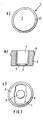
- FIGS. 1a, b, c show different views of a first embodiment
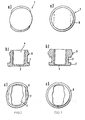
- FIGS. 2a, b, c show a second embodiment
- the FIGS. 3a, b, c show a third embodiment
- the FIGS. 4a, b, c show a fourth embodiment
- the FIGS. 5a, b, c show a fifth embodiment.
- FIG. 1a an ultrasonic transducer 1 in plan view. Visible, noticeable is the bottom of the pot, which is designed as a vibrating diaphragm 3. On the outer wall a stabilizing ring 6 is annularly arranged.
- FIG. 1b shows a sectional view in which the ultrasonic transducer 1 is shown in cross section. Visible is a pot-like housing with a relatively thick wall 2, the vibrating diaphragm 3 as a pot bottom and with the stabilizing ring 6. On the inside is on the bottom of the pot, a vibrating element 5, preferably applied by gluing, so that it has a good mechanical contact with the vibrating diaphragm 3 , The interior of the housing is referred to as recess 4.
- Figure c shows a rear plan view into the housing.
- the recess 4 has an approximately rectangular cross-sectional area, which limits the vibrating diaphragm 3 at the same time.
- electrical supply lines to the oscillating element 5 have been omitted in order to maintain clarity.
- the stabilizing ring 6 In the second embodiment according to the Figures 2a-c it is proposed to form the stabilizing ring 6 approximately oval in approximately parallel to the cross-sectional area of the recess 4.
- the wall 2 is thus formed approximately rectangular in the rear part, while in the region of the vibrating diaphragm 3, however, is circular.
- the circular structure forms a sound converter 7, which causes a limitation of the sound waves.
- the sounder 7 is formed flush with the outer surface of the vibrating diaphragm 3 and is rectangular in cross-section.
- the dimensions of the individual elements are on the one hand dependent on the working frequency, on the other hand on the available installation dimensions, for example in the bumper of a motor vehicle. The individual dimensions are expediently determined by comparative experiments.
- the embodiments according to the Figures 3 - 5 are from the embodiment according to the FIG. 2 derived.
- the third embodiment largely corresponds to the second embodiment.
- the recess 4 is made approximately rectangular.
- the stabilizing ring is, however, rotationally symmetrical in shape and formed much stronger than in the second embodiment ( FIG. 3b ).
- the fourth embodiment according to the FIGS. 4a-c differs from the third embodiment, essentially by the constriction of the wall 2.
- the acoustic funnel 7 is formed conically on its back. As a result, an acoustic decoupling of the rear pot area from the oscillating membrane is partially achieved.
- the sounder 7 is conically formed on the outer base, so that it forms a small funnel in conjunction with the vibrating diaphragm 3.
- the propagation and reception lobe is even more malleable.
- the mass of unwanted resonant material so that the decay time (Nachschwingzeit) of the ultrasonic transducer is reduced after switching off the exciter pulse. This has the consequence that the smallest measurable distance compared to known ultrasonic sensors is smaller, so that this sensor is particularly suitable for installation in a parking aid, since with him and tight space conditions are advantageously detectable.
Landscapes
- Physics & Mathematics (AREA)
- Engineering & Computer Science (AREA)
- Acoustics & Sound (AREA)
- Multimedia (AREA)
- Transducers For Ultrasonic Waves (AREA)
- Measurement Of Velocity Or Position Using Acoustic Or Ultrasonic Waves (AREA)
- Separation Using Semi-Permeable Membranes (AREA)
Description
- Die Erfindung geht aus von einem Ultraschallwandler mit einem topfähnlichen Gehäuse nach der Gattung des Hauptanspruchs. Aus der
EP 0075302 B1 ist bereits ein Ultraschallwandler bekannt, der ein topfförmiges Gehäuse aufweist. Auf der Innenseite ist auf dem Topfboden ein piezokeramisches Schwingelement aufgebracht. Um Oberwellen zu dämpfen und die Ausbreitungs- bzw. Empfangskeule dieser Anordnung zu formen, sind an der Innenseite des topfförmigen Wandlergehäuses an zwei gegenüberliegenden Seiten kreisabschnittsförmige Dämpfungskörper angebracht. Zur Befestigung wird der Ultraschallwandler in ein Gehäuse aus Weichplastik oder Weichgummi eingebracht. Ungünstig bei dieser Konstruktion ist, daß durch die gleichmäßige Wanddicke des topfförmigen Gehäuses nicht nur die Membran, sondern auch die Gehäusewandung zur Schwingung angeregt wird, so daß sowohl die Sende- als auch die Empfangskeule durch Überlagerung von Oberwellen ungünstig beeinflußt bzw. ausgelöscht wird. - Aus der
EP 678 853 A2 US 4,823,042 ist ein Ultraschallwandler für eine medizinische Therapie bekannt, wobei an dem Wandlertopf ein Gewinde angeordnet ist, mit dem der Ultraschallwandler an einem Handgriff befestigt werden kann. Auf der einer Frontfläche gegenüberliegenden Seite ist ein piezoelektrischer Kristall zur Schwingungserzeugung angeordnet. Aus derUS 3,638,052 ist ein elektroakustischer Wandler bekannt, bei dem eine Schwingungsmembran in einer kreisförmigen Öffnung eines festen Gehäuses angeordnet ist. Durch die Ausgestaltung der Schwingungsmembran wird die Abstrahlcharakteristik des elektroakustischen Wandlers festgelegt. - Der erfindungsgemäße Ultraschallwandler mit den kennzeichnenden Merkmalen des Hauptanspruchs hat demgegenüber den Vorteil, daß durch den Stabilisierungsring an der Wandung des topfähnlichen Gehäuses eine größere Steifigkeit des Gehäuses erreicht wird, so daß der verbleibende Teil der Bodenfläche des Gehäuses als Schwingmembran wirkt, die vorzugsweise auf der Grundwelle schwingt. Besonders vorteilhaft ist, daß wegen der größeren Masse der Wandung auch die Nachschwingdauer der Schwingmembran verkürzt wird, so daß sich vorteilhaft insgesamt eine bessere Ausbreitungs- und Empfangskeule, sowie ein besseres Schwingverhalten ergibt. Insbesondere kann durch die verkürzte Nachschwingdauer eine Abstandsmessung, wie sie beispielsweise bei einer Einparkhilfe eines Kraftfahrzeuges auch bei sehr geringen Abständen zum Hindernis noch durchgeführt werden.
- Durch die in den abhängigen Ansprüchen aufgeführten Maßnahmen sind vorteilhafte Weiterbildungen und Verbesserungen des im Hauptanspruchs angegebenen Ultraschallwandlers möglich. Besonders vorteilhaft ist, daß durch die entfernte Anordnung des Stabilisierungsringes von der Wandung der Schwingmembran erreicht wird, daß der Sensorkopf auf ein minimales Einbaumaß reduziert werden kann, so daß sich beispielsweise nach dem Einbau in eine Stoßstange ein optimales Erscheinungsbild ergibt, das nicht störend wirkt.
- Der Stabilisierungsring wird bereits bei der Herstellung des Gehäuses gebildet, so daß die Herstellkosten relativ günstig sind.
- Um die Ausbreitungskeule vorteilhaft zu formen, wird an der Außenseite der Wandung im Bereich der Schwingmembran ein Schallrichter angeordnet. Je nach Verwendungszweck kann der Schallrichter so ausgebildet werden, daß sich in der horizontalen eine möglichst breite Ausbreitungskeule und in der vertikalen Richtung eine möglichst schmale Ausbreitungskeule ergibt. Der Schallrichter ist als Ring ausgebildet und umschließt die Schwingmembran. Bei entsprechender Ausgestaltung des Schallrichters ist darüber hinaus auch vorteilhaft, die Reichweite des Ultraschallwandlers vorgebbar.
- Um bevorzugt ein unauffälliges Erscheinungsbild zu geben, wird der Schallrichter mit der Ebene der Schwingmembran bündig ausgeführt. In alternativer Ausführungsform ist er jedoch auch kegelförmig ausgebildet, um die Ausbreitungs- und Empfangskeule der Ultraschallwellen noch stärker zu beeinflussen. Um bessere Einbaubedingungen zu schaffen, ist vorgesehen, den Querschnitt des Schallrichters entweder rechteckförmig oder kegelförmig auszubilden.
- In der Zeichnung sind mehrere Ausführungsformen dargestellt und in der nachfolgenden Beschreibung näher erläutert. Die
Figuren 1a, b, c zeigen unterschiedliche Ansichten eines ersten Ausführungsbeispiels,Figuren 2a, b, c zeigen ein zweites Ausführungsbeispiel, dieFiguren 3a, b, c zeigen ein drittes Ausführungsbeispiel, dieFiguren 4a, b, c zeigen ein viertes Ausführungsbeispiel und dieFiguren 5a, b, c zeigen ein fünftes Ausführungsbeispiel. - Bei dem ersten Ausführungsbeispiel zeigt
Figur 1a einen Ultraschallwandler 1 in Draufsicht. Sichtbar ist der Topfboden, der als Schwingmembran 3 ausgebildet ist. An der Außenwandung ist ringförmig ein Stabilisierungsring 6 angeordnet.Figur 1b zeigt ein Schnittbild, bei dem der Ultraschallwandler 1 im Querschnitt dargestellt ist. Erkennbar ist ein topfähnliches Gehäuse mit einer relativ dicken Wandung 2, der Schwingmembran 3 als Topfboden und mit dem Stabilisierungsring 6. Auf der Innenseite ist auf dem Topfboden ein Schwingelement 5, vorzugsweise durch Kleben aufgebracht, so daß es einen guten mechanischen Kontakt zur Schwingmembran 3 hat. Der Innenraum des Gehäuses wird als Aussparung 4 bezeichnet. Figur c zeigt eine rückwärtige Draufsicht in das Gehäuse hinein. Die Aussparung 4 hat eine etwa rechteckförmige Querschnittsfläche, die gleichzeitig die Schwingmembran 3 begrenzt. Vollständigkeitshalber wird darauf hingewiesen, daß elektrische Zuleitungen zum Schwingelement 5 weggelassen wurden, um die Übersichtlichkeit zu wahren. - Bei den nachfolgend beschriebenen Ausführungsbeispielen werden die gleichen Bezugszeichen verwendet, wie sie für vergleichbare Teile beim ersten Ausführungsbeispiel vorgeschlagen wurden. Da der Aufbau der nachfolgenden Ausführungsbeispiele im wesentlichen identisch ist mit dem des ersten Ausführungsbeispiels, werden nur die wesentlichen Abweichungen näher erläutert. Die Darstellungsformen sind jedoch vergleichbar mit denen des ersten Ausführungsbeispieles.
- Beim zweiten Ausführungsbeispiel gemäß den
Figuren 2a-c wird vorgeschlagen, den Stabilisierungsring 6 etwa oval in etwa parallel zur Querschnittsfläche der Aussparung 4 auszubilden. Die Wandung 2 ist somit im hinteren Teil etwa rechteckförmig geformt, während sie im Bereich der Schwingmembran 3 jedoch kreisrund ist. Die kreisrunde Struktur bildet einen Schallrichter 7, der eine Begrenzung der Schallwellen bewirkt. Der Schallrichter 7 ist bündig mit der Außenfläche Schwingmembran 3 ausgebildet und ist im Querschnitt rechteckförmig geformt. Die Abmessungen der einzelnen Elemente sind einerseits von der Arbeitsfrequenz abhängig, andererseits von den verfügbaren Einbaumaßen, beispielsweise im Stoßfänger eines Kraftfahrzeugs. Die Einzelmaße werden zweckmäßigerweise durch Vergleichsversuche ermittelt. - Die Ausführungsbeispiele gemäß der
Figuren 3 - 5 sind aus dem Ausführungsbeispiel gemäß derFigur 2 hergeleitet. Das dritte Ausführungsbeispiel entspricht weitgehend dem zweiten Ausführungsbeispiel. Die Aussparung 4 ist etwa rechteckförmig ausgeführt. Der Stabilisierungsring ist allerdings rotationssymetrisch geformt und wesentlich stärker ausgebildet als beim zweiten Ausführungsbeispiel (Figur 3b ). - Das vierte Ausführungsbeispiel gemäß der
Figuren 4a - c unterscheidet sich vom dritten Ausführungsbeispiel im wesentlichen durch die Einschnürung der Wandung 2. Der Schallrichter 7 ist auf seiner Rückseite kegelförmig ausgebildet. Dadurch wird teilweise eine akustische Abkoplung des hinteren Topfbereiches von der schwingenden Membran erreicht. - Beim fünften Ausführungsbeispiel gemäß der
Figuren 5a-c ist darüber hinaus der Schallrichter 7 an der äußeren Grundfläche kegelförmig ausgebildet, so daß er in Verbindung mit der Schwingmembran 3 einen kleinen Trichter bildet. Dadurch ist die Ausbreitungs- und Empfangskeule noch stärker formbar. Darüber hinaus ist bei den Ausführungsbeispielen gemäß derFiguren 1- 5 durch die Einschnürung der Wandung 2 die Masse des ungewollt mitschwingenden Materials verkleinert, so daß die Abklingdauer (Nachschwingzeit) des Ultraschallwandlers nach dem Abschalten des Erregerimpulses vermindert wird. Dies hat zur Folge, daß der kleinste meßbare Abstand gegenüber bekannten Ultraschallsensoren kleiner wird, so daß sich dieser Sensor insbesondere für den Einbau in eine Einparkhilfe eignet, da mit ihm auch enge Raumverhältnisse vorteilhaft erfaßbar sind.
Claims (8)
- Ultraschallwandler mit einem topfähnlichen Gehäuse mit einer ringförmigen Wandung und einer Bodenfläche als Schwingungsmembran, wobei auf der Innenseite der Bodenfläche ein Piezoelement als Schwingelement aufgebracht ist, wobei die Wandung (2) unterschiedliche Wandstärken aufweist und wobei nur ein Teil der äußeren Bodenfläche als Schwingungsmembran (3) wirkt, dadurch gekennzeichnet, dass an der Außenseite der Wandung (2) des Ultraschallwandlers (1) ein Stabilisierungsring (6) angeordnet ist, dass sich der Stabilisierungsring (6) über die übrige Wandung (2) erhebt und dass der Innenraum (4) des Gehäuses eine etwa rechteckförmige Querschnittsfläche aufweist, die die Schwingungsmembran (3) begrenzt.
- Ultraschallwandler nach Anspruch 1, dadurch gekennzeichnet, dass der Stabilisierungsring (6) an der Wandung (2) von der Schwingungsmembran (3) entfernt angeordnet ist.
- Ultraschallwandler nach Anspruch 1 oder 2, dadurch gekennzeichnet, dass der Stabilisierungsring (6) aus dem Material des Gehäuses besteht.
- Ultraschallwandler nach einem der vorhergehenden Ansprüche, dadurch gekennzeichnet, dass im Bereich der Schwingungsmembran (3) an der Außenseite der Wandung (2) ein Schallrichter (7) angeordnet ist.
- Ultraschallwandler nach Anspruch 4, dadurch gekennzeichnet, dass der Schallrichter (7) als Ring ausgebildet ist, der die Schwingungsmembran (3) umfasst.
- Ultraschallwandler nach Anspruch 4 oder 5, dadurch gekennzeichnet, dass der Schallrichter (7) bündig mit der Schwingungsmembran (3) abschließt
- Ultraschallwandler nach Anspruch 4 oder 5, dadurch gekennzeichnet, dass der Schallrichter (7) in Verbindung mit der Schwingungsmembran (3) einen Trichter bildet.
- Ultraschallwandler nach einem der Ansprüche 4 bis 7, dadurch gekennzeichnet, dass der Schallrichter (7) in Bezug auf die Wandung (2) kegelförmig ausgebildet ist und die Wandung (2) einschnürt.
Applications Claiming Priority (3)
| Application Number | Priority Date | Filing Date | Title |
|---|---|---|---|
| DE19727877A DE19727877A1 (de) | 1997-06-30 | 1997-06-30 | Ultraschallwandler |
| DE19727877 | 1997-06-30 | ||
| PCT/DE1998/001734 WO1999001234A2 (de) | 1997-06-30 | 1998-06-25 | Ultraschallwandler |
Publications (3)
| Publication Number | Publication Date |
|---|---|
| EP0993344A2 EP0993344A2 (de) | 2000-04-19 |
| EP0993344B1 EP0993344B1 (de) | 2003-01-29 |
| EP0993344B2 true EP0993344B2 (de) | 2008-10-15 |
Family
ID=7834178
Family Applications (1)
| Application Number | Title | Priority Date | Filing Date |
|---|---|---|---|
| EP98941228A Expired - Lifetime EP0993344B2 (de) | 1997-06-30 | 1998-06-25 | Ultraschallwandler |
Country Status (5)
| Country | Link |
|---|---|
| US (1) | US6465935B1 (de) |
| EP (1) | EP0993344B2 (de) |
| JP (1) | JP4263251B2 (de) |
| DE (2) | DE19727877A1 (de) |
| WO (1) | WO1999001234A2 (de) |
Families Citing this family (17)
| Publication number | Priority date | Publication date | Assignee | Title |
|---|---|---|---|---|
| JP3324593B2 (ja) | 1999-10-28 | 2002-09-17 | 株式会社村田製作所 | 超音波振動装置 |
| JP3972610B2 (ja) * | 2001-07-26 | 2007-09-05 | 松下電工株式会社 | 超音波美容器 |
| DE10136628B4 (de) * | 2001-07-26 | 2006-04-20 | Valeo Schalter Und Sensoren Gmbh | Ultraschallwandler zum Aussenden und Empfangen von Ultraschallwellen mittels einer Membran, Verfahren und Steuergerät zum Betrieb des Ultraschallwandlers, sowie Verwendung des Ultraschallwandlers |
| DE10304001A1 (de) * | 2003-02-01 | 2004-08-12 | Valeo Schalter Und Sensoren Gmbh | Topfförmige Menbrane für einen Sensor, insbesondere einen Ultraschallsensor und Sensor, insbesondere Ultraschallsensor |
| JP2007114182A (ja) * | 2005-09-22 | 2007-05-10 | Denso Corp | 超音波センサの取付け構造 |
| DE102005046173A1 (de) * | 2005-09-27 | 2007-04-05 | Siemens Ag | Ultraschallwandler für verdeckten Einbau |
| EP1906383B1 (de) * | 2006-09-29 | 2013-11-13 | Tung Thih Electronic Co., Ltd. | Ultraschallgerät-Sende-/Empfangsvorrichtung |
| DE102006050037A1 (de) * | 2006-10-24 | 2008-04-30 | Robert Bosch Gmbh | Ultraschallwandler |
| ITMO20070377A1 (it) * | 2007-12-07 | 2009-06-08 | Meta System Spa | Dispositivo per il rilevamento di oggetti in prossimita' di veicoli, impiegabile in particolare in sistemi di assistenza al parcheggio o simili |
| DE102008040905A1 (de) * | 2008-07-31 | 2010-02-04 | Robert Bosch Gmbh | Ultraschallsensor |
| DE102011004845A1 (de) | 2011-02-28 | 2012-08-30 | BSH Bosch und Siemens Hausgeräte GmbH | Kolbenverdichter und Kältegerät mit einem Kolbenverdichter |
| DE102012209238A1 (de) * | 2012-05-31 | 2013-12-05 | Robert Bosch Gmbh | Ultraschallsensor sowie Vorrichtung und Verfahren zur Messung eines Abstands zwischen einem Fahrzeug und einem Hindernis |
| DE102012109838A1 (de) * | 2012-10-16 | 2014-04-17 | Volkswagen Ag | Ultraschallsensorvorrichtung mit einer Versteifungseinheit, Anordnung, Kraftfahrzeug und Verfahren zum Herstellen einer Anordnung |
| DE102017223089A1 (de) | 2017-12-18 | 2019-06-19 | Robert Bosch Gmbh | Sensoranordnung zum Senden und/oder Empfangen eines Schallsignals |
| US12207054B2 (en) | 2018-10-24 | 2025-01-21 | Cochlear Limited | Implantable transducer with integrated diaphragm |
| DE102021133906A1 (de) * | 2021-12-20 | 2023-06-22 | Tdk Electronics Ag | Ultraschallwandler mit Gehäuse |
| DE102024108606A1 (de) | 2024-03-26 | 2025-10-02 | Valeo Schalter Und Sensoren Gmbh | Ultraschallsensorvorrichtung für ein Fahrzeug sowie Verfahren zum Betreiben einer Ultraschallsensorvorrichtung |
Citations (6)
| Publication number | Priority date | Publication date | Assignee | Title |
|---|---|---|---|---|
| US3890423A (en) † | 1973-07-27 | 1975-06-17 | Nusonics | Electroacoustic transducer assembly |
| EP0075302A1 (de) † | 1981-09-23 | 1983-03-30 | Egon Gelhard | Sensor für die Durchführung einer Distanzmessung nach dem Ultraschall-Echoprinzip |
| EP0283823A1 (de) † | 1987-03-20 | 1988-09-28 | Siemens Aktiengesellschaft | Gerät zur Erzeugung und Abstrahlung von Ultraschall,insbesondre für Ultraschall-Therapie |
| DE3941933A1 (de) † | 1989-12-19 | 1991-06-20 | Siemens Ag | Ultraschallwandler fuer luftstroemungsmessung insbesondere zur luftmengenmessung bei verbrennungsmotoren |
| DE4120681A1 (de) † | 1990-08-04 | 1992-02-06 | Bosch Gmbh Robert | Ultraschallwandler |
| DE4215271A1 (de) † | 1992-05-09 | 1993-11-11 | Tridelta Ag | Ultraschallwandler |
Family Cites Families (12)
| Publication number | Priority date | Publication date | Assignee | Title |
|---|---|---|---|---|
| DE351626C (de) | 1918-02-23 | 1922-04-15 | Signal Ges M B H | Einrichtung zur UEbertragung und Aufnahme von Schallwellen in Fluessigkeiten |
| US3638052A (en) * | 1969-09-22 | 1972-01-25 | Dynamics Corp America | Electroacoustic transducers of the bilaminar flexural vibrating type |
| US3943388A (en) * | 1974-06-27 | 1976-03-09 | Fred M. Dellorfano, Jr. | Electroacoustic transducer of the flexural vibrating diaphragm type |
| US4607186A (en) | 1981-11-17 | 1986-08-19 | Matsushita Electric Industrial Co. Ltd. | Ultrasonic transducer with a piezoelectric element |
| DE3324575C2 (de) | 1982-07-22 | 1985-06-27 | Siemens AG, 1000 Berlin und 8000 München | Behandlungskopf zur therapeutischen Applikation von Ultraschall |
| DE3441684A1 (de) * | 1984-11-15 | 1986-05-15 | SWF Auto-Electric GmbH, 7120 Bietigheim-Bissingen | Elektroakustischer wandler |
| US4823042A (en) * | 1986-07-18 | 1989-04-18 | Rich-Mar Corporation | Sonic transducer and method for making the same |
| DE3732412A1 (de) * | 1987-09-25 | 1989-04-13 | Siemens Ag | Ultraschallwandler mit astigmatischer sende-/empfangscharakteristik |
| DE4413894C2 (de) * | 1994-04-21 | 2002-12-12 | Teves Gmbh Alfred | Biegewandler in Topfform |
| DE19527018C1 (de) * | 1995-07-24 | 1997-02-20 | Siemens Ag | Ultraschallwandler |
| DE19630350C2 (de) * | 1996-07-26 | 1998-08-20 | Siemens Ag | Ultraschallwandler |
| JP3721798B2 (ja) * | 1998-01-13 | 2005-11-30 | 株式会社村田製作所 | 超音波センサ |
-
1997
- 1997-06-30 DE DE19727877A patent/DE19727877A1/de not_active Withdrawn
-
1998
- 1998-06-25 EP EP98941228A patent/EP0993344B2/de not_active Expired - Lifetime
- 1998-06-25 DE DE59807074T patent/DE59807074D1/de not_active Expired - Lifetime
- 1998-06-25 US US09/462,003 patent/US6465935B1/en not_active Expired - Lifetime
- 1998-06-25 WO PCT/DE1998/001734 patent/WO1999001234A2/de not_active Ceased
- 1998-06-25 JP JP50609599A patent/JP4263251B2/ja not_active Expired - Lifetime
Patent Citations (6)
| Publication number | Priority date | Publication date | Assignee | Title |
|---|---|---|---|---|
| US3890423A (en) † | 1973-07-27 | 1975-06-17 | Nusonics | Electroacoustic transducer assembly |
| EP0075302A1 (de) † | 1981-09-23 | 1983-03-30 | Egon Gelhard | Sensor für die Durchführung einer Distanzmessung nach dem Ultraschall-Echoprinzip |
| EP0283823A1 (de) † | 1987-03-20 | 1988-09-28 | Siemens Aktiengesellschaft | Gerät zur Erzeugung und Abstrahlung von Ultraschall,insbesondre für Ultraschall-Therapie |
| DE3941933A1 (de) † | 1989-12-19 | 1991-06-20 | Siemens Ag | Ultraschallwandler fuer luftstroemungsmessung insbesondere zur luftmengenmessung bei verbrennungsmotoren |
| DE4120681A1 (de) † | 1990-08-04 | 1992-02-06 | Bosch Gmbh Robert | Ultraschallwandler |
| DE4215271A1 (de) † | 1992-05-09 | 1993-11-11 | Tridelta Ag | Ultraschallwandler |
Also Published As
| Publication number | Publication date |
|---|---|
| WO1999001234A3 (de) | 1999-04-22 |
| JP2002507370A (ja) | 2002-03-05 |
| EP0993344A2 (de) | 2000-04-19 |
| DE19727877A1 (de) | 1999-01-07 |
| JP4263251B2 (ja) | 2009-05-13 |
| WO1999001234A2 (de) | 1999-01-14 |
| EP0993344B1 (de) | 2003-01-29 |
| DE59807074D1 (de) | 2003-03-06 |
| US6465935B1 (en) | 2002-10-15 |
Similar Documents
| Publication | Publication Date | Title |
|---|---|---|
| EP0993344B2 (de) | Ultraschallwandler | |
| DE2937942C2 (de) | Ultraschallwandler | |
| EP2856206B1 (de) | Ultraschallsensor sowie vorrichtung und verfahren zur messung eines abstands zwischen einem fahrzeug und einem hindernis | |
| DE4238924A1 (de) | Elektroakustischer Wandler | |
| DE102007045809A1 (de) | Detektorvorrichtung für ein Hindernis | |
| EP0507892B1 (de) | Ultraschallwandler | |
| DE19917862B4 (de) | Ultraschallsensor | |
| DE2541492C3 (de) | Ultraschallwandler | |
| DE19857024B4 (de) | Lautsprecher | |
| DE19832072B4 (de) | Piezoelektrischer elektroakustischer Konverter | |
| EP2660627B1 (de) | Sensoranordnung umfassend eine flächige Fahrzeugkomponente und einen Ultraschallsensor | |
| DE102008040905A1 (de) | Ultraschallsensor | |
| EP0802521A2 (de) | Sensor zum Senden und/oder Empfangen akustischer Signale | |
| DE102013211606A1 (de) | Umfeldsensiereinrichtung mit Ultraschallwandler, und Kraftfahrzeug mit einer derartigen Umfeldsensiereinrichtung | |
| DE102017108341B4 (de) | Ultraschallsensorvorrichtung für ein Kraftfahrzeug mit einer Sendeeinrichtung und separaten Empfangseinrichtungen, Fahrerassistenzsystem sowie Kraftfahrzeug | |
| DE112021002364T5 (de) | Ultraschallsensor | |
| DE112020002082B4 (de) | Ultraschallsensor | |
| EP3010653B1 (de) | Elektroakustischer wandler | |
| DE4114180C2 (de) | Ultraschallwandler | |
| DE19912772C2 (de) | Ultraschallsensor zur Abstandsmessung | |
| DE2944998A1 (de) | Hornanordnung mit einem elektroakustischen wandler | |
| DE102017209823A1 (de) | Ultraschallsensor | |
| DE19754891C1 (de) | Ultraschallwandler | |
| DE1167076B (de) | Mechanische Impedanzanpassresonatorvorrichtung | |
| DE10009129A1 (de) | Ultraschallsensor |
Legal Events
| Date | Code | Title | Description |
|---|---|---|---|
| PUAI | Public reference made under article 153(3) epc to a published international application that has entered the european phase |
Free format text: ORIGINAL CODE: 0009012 |
|
| 17P | Request for examination filed |
Effective date: 20000131 |
|
| AK | Designated contracting states |
Kind code of ref document: A2 Designated state(s): DE FR GB IT SE |
|
| 17Q | First examination report despatched |
Effective date: 20001228 |
|
| GRAG | Despatch of communication of intention to grant |
Free format text: ORIGINAL CODE: EPIDOS AGRA |
|
| GRAG | Despatch of communication of intention to grant |
Free format text: ORIGINAL CODE: EPIDOS AGRA |
|
| GRAH | Despatch of communication of intention to grant a patent |
Free format text: ORIGINAL CODE: EPIDOS IGRA |
|
| GRAH | Despatch of communication of intention to grant a patent |
Free format text: ORIGINAL CODE: EPIDOS IGRA |
|
| GRAA | (expected) grant |
Free format text: ORIGINAL CODE: 0009210 |
|
| AK | Designated contracting states |
Designated state(s): DE FR GB IT SE |
|
| REG | Reference to a national code |
Ref country code: GB Ref legal event code: FG4D Free format text: NOT ENGLISH |
|
| REF | Corresponds to: |
Ref document number: 59807074 Country of ref document: DE Date of ref document: 20030306 Kind code of ref document: P |
|
| REG | Reference to a national code |
Ref country code: SE Ref legal event code: TRGR |
|
| GBT | Gb: translation of ep patent filed (gb section 77(6)(a)/1977) |
Effective date: 20030509 |
|
| ET | Fr: translation filed | ||
| PLBQ | Unpublished change to opponent data |
Free format text: ORIGINAL CODE: EPIDOS OPPO |
|
| PLBI | Opposition filed |
Free format text: ORIGINAL CODE: 0009260 |
|
| PLAX | Notice of opposition and request to file observation + time limit sent |
Free format text: ORIGINAL CODE: EPIDOSNOBS2 |
|
| 26 | Opposition filed |
Opponent name: VALEO SCHALTER UND SENSOREN GMBH Effective date: 20031029 |
|
| PLBB | Reply of patent proprietor to notice(s) of opposition received |
Free format text: ORIGINAL CODE: EPIDOSNOBS3 |
|
| APBP | Date of receipt of notice of appeal recorded |
Free format text: ORIGINAL CODE: EPIDOSNNOA2O |
|
| APAH | Appeal reference modified |
Free format text: ORIGINAL CODE: EPIDOSCREFNO |
|
| APAY | Date of receipt of notice of appeal deleted |
Free format text: ORIGINAL CODE: EPIDOSDNOA2O |
|
| APBP | Date of receipt of notice of appeal recorded |
Free format text: ORIGINAL CODE: EPIDOSNNOA2O |
|
| APBQ | Date of receipt of statement of grounds of appeal recorded |
Free format text: ORIGINAL CODE: EPIDOSNNOA3O |
|
| APBU | Appeal procedure closed |
Free format text: ORIGINAL CODE: EPIDOSNNOA9O |
|
| PUAH | Patent maintained in amended form |
Free format text: ORIGINAL CODE: 0009272 |
|
| STAA | Information on the status of an ep patent application or granted ep patent |
Free format text: STATUS: PATENT MAINTAINED AS AMENDED |
|
| 27A | Patent maintained in amended form |
Effective date: 20081015 |
|
| AK | Designated contracting states |
Kind code of ref document: B2 Designated state(s): DE FR GB IT SE |
|
| REG | Reference to a national code |
Ref country code: SE Ref legal event code: RPEO |
|
| REG | Reference to a national code |
Ref country code: FR Ref legal event code: PLFP Year of fee payment: 19 |
|
| REG | Reference to a national code |
Ref country code: FR Ref legal event code: PLFP Year of fee payment: 20 |
|
| PGFP | Annual fee paid to national office [announced via postgrant information from national office to epo] |
Ref country code: FR Payment date: 20170621 Year of fee payment: 20 Ref country code: GB Payment date: 20170626 Year of fee payment: 20 |
|
| PGFP | Annual fee paid to national office [announced via postgrant information from national office to epo] |
Ref country code: SE Payment date: 20170626 Year of fee payment: 20 |
|
| PGFP | Annual fee paid to national office [announced via postgrant information from national office to epo] |
Ref country code: IT Payment date: 20170622 Year of fee payment: 20 Ref country code: DE Payment date: 20170809 Year of fee payment: 20 |
|
| REG | Reference to a national code |
Ref country code: DE Ref legal event code: R071 Ref document number: 59807074 Country of ref document: DE |
|
| REG | Reference to a national code |
Ref country code: GB Ref legal event code: PE20 Expiry date: 20180624 |
|
| PG25 | Lapsed in a contracting state [announced via postgrant information from national office to epo] |
Ref country code: GB Free format text: LAPSE BECAUSE OF EXPIRATION OF PROTECTION Effective date: 20180624 |